1111Di0 CORPORATION o! AM. ilde LIVPSION HARRISON, N.
|
|
|
- Kelley Parrish
- 5 years ago
- Views:
Transcription


1 1111Di0 CORPORATION o! AM ilde LIVPSION HARRISON, N.
2 CONTENTS PAGE POWER -TUBE FUNDAMENTALS 3 Basic Considerations, Vacuum Tubes, Gas Tubes, Generic Tube Types, Diodes, Triodes, Tetrodes, Pentodes, Beam Power Tubes CONSTRUCTION AND MATERIALS 10 Cathodes, Plates, Grids, Internal Insulation, Getters, Envelopes POWER -TUBE APPLICATIONS 15 Amplification, Class A Amplifiers, Class B Amplifiers, Class AB Amplifiers, Class C Amplifiers, Class C Telegraphy, Modulated Class C Amplifiers, Frequency Multiplication, Oscillators, Circuit Configuration POWER -TUBE CIRCUIT -DESIGN CONSIDERATIONS 28 Tube Selection, Multi -Tube Stages, AF Power Amplifiers, Modulators, RF Power Amplifiers, Driving Power, Grid -Bias Considerations, Frequency Multipliers, Oscillators, Parallel -Tuned Tank Circuits, Inter - stage Coupling, Output Coupling, Stabilization, Parasitic Oscillations, Power -Supply Considerations; Calculation of Operating Conditions; Use of Curves; Class C Telegraphy Service- Multigrid Tubes, Triodes; Plate -Modulated Class C Telephony Service; Frequency Multipliers; Class AB and Class B AF Amplifier Service; Class AB: Amplifiers - Multigrid Tubes; Class B Amplifiers- Triodes; Conversion Factors; Adjustment and Tuning, Tuning Procedure, Neutralizing Adjustments POWER -TUBE INSTALLATION 58 Ventilation, Wiring Considerations, Circuit Returns, Filament or Heater Supply, Plate Supply, Suppressor -Grid Supply, Screen -Grid Supply, Control -Grid (Bias) Supply, Supply -Voltage Variations, Protective Devices, Safety Considerations RECTIFIER CONSIDERATIONS 65 Mercury -Vapor Tubes, Filament Heating Time, Mercury Temperature, Shielding, Tube Ratings, Circuits, Quadrature Operation, Regulation, Filters, Design of Choke -Input Filters INTERPRETATION OF TUBE DATA 78 CHARTS 80 TUBE TYPES- Technical Data 87 OUTLINES 220 CIRCUITS 233 INDEX 247 READING LIST 256 Marca Registrada Devices and arrangements shown or described herein may use patents of RCA or others. Information contained herein is furnished without responsibility by RCA for its use and without prejudice to RCA's patent rights Printed in U. S. A.
3 RCA Transmitting Tubes THIS MANUAL has been prepared to assist those who work or experiment with transmitting tubes and circuits. It will be found valuable by engineers, service technicians, radio amateurs, students, experimenters, and all others technically interested in transmitting tubes. Power types having plate -input ratings up to four kilowatts and associated rectifier types are included in this Manual. In the TUBE TYPES Section, detailed information is given on all important RCA types in this category. Essential basic data for discontinued RCA types are included for reference purposes. In addition to the tube types covered in this Manual, the TUBE DIVISION OF RADIO CORPORATION OF AMERICA offers a variety of high -power and super -power tubes for transmitting and industrial applications. Other lines of RCA electron devices include: RECEIVING TUBES Rectifiers, Diode - Detectors, Voltage and Power Amplifiers, Converters, Oscillators, and Mixers TELEVISION CAMERA TUBES Iconoscopes, Monoscopes, Vidicons, and Image Orthicons PHOTOTUBES Single -Unit, Twin -Unit, and Multiplier Types PICTURE TUBES Black -and -White and Color THYRATRONS & IGNITRONS CATHODE -RAY TUBES Special- Purpose Kinescopes, Storage Tubes, and Oscillograph Types SPECIAL TYPES "Special Red" Tubes, Vacuum - Gauge Tubes, Magnetrons, Traveling -Wave Tubes, and Receiving -Type Tubes for Industrial Applications SEMICONDUCTOR DEVICES Transistors and Diodes For Sales Information, write to Sales For Technical Information, write to Commercial Engineering TUBE DIVISION RADIO CORPORATION OF AMERICA Harrison, N. J. 1956, Radio Corporation of America, (all rights reserved)
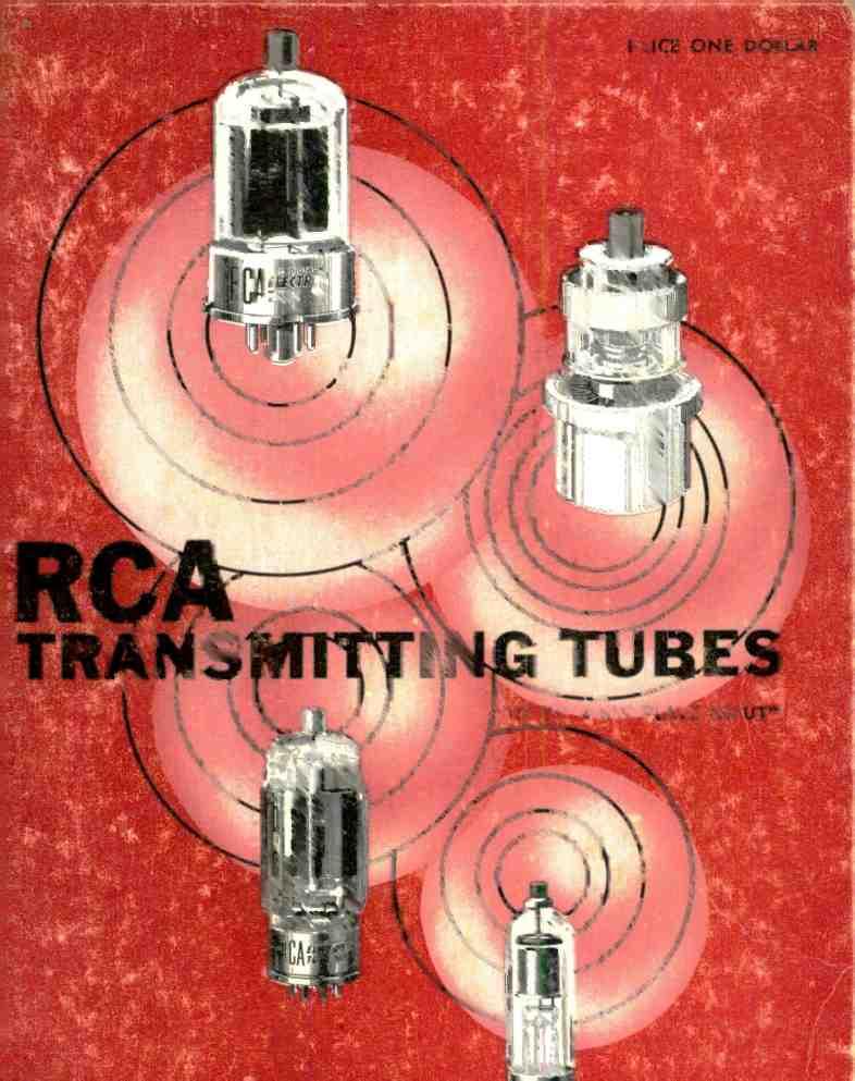
4 Popular VHF Beam Power Tubes for fixed- station and mobile service 2
5 RCA Transmitting Tubes Power -Tube Fundamentals Power tubes are devices for controlling the transfer of energy in electrical circuits. In this respect they are similar to rheostats, switches, and other circuit -type control devices.tubes, however, permit much more rapid, precise, and efficient control of electrical energy than mechanically operated devices. The transfer of electrical energy through a circuit involves control of two factors, rate and direction. The rate of energy transfer is determined by the number of individual electron charges moving unidirectionally through the circuit in a given interval of time and is proportional to the applied voltage. The direction in which the electron charges move is determined by the polarity of the applied voltage. Electron charges may be transferred through a circuit element by several methods. In one method, kinetic energy is transferred between adjacent electrons within the molecular structure of a conductor. This method is employed in switches, rheostats, and other devices which utilize conductive materials as control electrodes. Because the currents through such devices are controlled by mechanical means, the speed with which the amount or direction of current can be changed is limited by friction and inertia. In a second method, individual electrons are transferred through a low - density, nonconductive medium, such as a vacuum or a low- pressure gas. This method is used in tubes and has the advantage that both the rate and the direction of current flow may be controlled by electric fields. Because these fields, as well as the electrons, have negligible inertia, tubes can effect changes in the value and direction of electric current at speeds considerably higher than those 3 obtainable with mechanically operated devices. In electrical circuits, control of the direction of current flow is necessary when the power source produces ac voltages and currents and the load requires a unidirectional current. Tubes which are used primarily to control the direction of current flow are known as rectifiers. All such tubes, however, are also rate -control or rate -limiting devices in the sense that they have a finite current - carrying capability. Rate -control requirements in electrical circuits range from occasional onoff switching to continuous variations occurring several billion times per second. Tubes which provide this form of control are known generically as amplifiers. Power -tube amplifiers are capable of controlling relatively large amounts of energy. All triode and multigrid power tubes are inherently rectifiers as well as amplifiers because they deliver unidirectional current regardless of the kind of energy furnished by the power source. Basic Considerations In its simplest form, an electron tube consists of a cathode (the negative electrode) and an anode or plate (the positive electrode) in a sealed envelope. More complex types may also contain one or more additional electrodes. The purpose of the cathode is to furnish a continuous supply of free electrons; the plate collects these electrons. The rate at which electrons are collected by the plate (the plate current) is determined by the number of free electrons available and by the polarity and the strength of the electric field between the plate and cathode. Power tubes and rectifiers are usually operated so that the number of electrons available is constant. Conse-
6 quently, the rate of collection or current flow is determined principally by the characteristics of the internal electric field. The internal electric field is established by connection of a source of potential between the plate and cathode. When the plate is at a negative potential with respect to the cathode, the internal field tends to prevent electrons from leaving the vicinity of the cathode, and there is no transfer of energy through the tube. When the plate is operated at a positive potential with respect to the cathode, the field causes a movement of electrons to the plate. The current through the tube is then determined by the strength of the field, or the plate voltage. Vacuum Tubes Under normal operating conditions, the velocity of the electrons emitted by the cathode of a vacuum tube is just sufficient to insure their release from the emitting surface. If no accelerating field is applied, these electrons tend to return to the cathode when their escape energy has been expended. However, the intense negative field created by new electrons reaching the emitting surface repels those previously emitted and they accumulate in the space surrounding the cathode. This accumulation of electrons is called the space charge. The approximate distribution of the space- charge electrons in the absence of an accelerating field is shown in Fig. 1. The concentration is greatest in CATHODE SPACE CHARGE Fig. 1 RCA Transmitting Tubes PLATE the region nearest the cathode. The general relationship between plate voltage (Eb) and plate current (Ib) in a two - electrode vacuum tube is shown in Fig. 2. At very low positive plate voltages (region E. to E,), only the loosely bound electrons on the outer surface of the 4 space charge are attracted to the plate, and the plate current does not change uniformly with equal increments in plate voltage. Over a higher range of plate voltages (region E, to E2), the relation between plate voltage and plate current is nearly linear. When operated Ep E; E2 PLATE VOLTAGE Fig. 2 in this region, a two -electrode vacuum tube has substantially constant internal resistance (called plate resistance, or rp), and the plate current follows the normal Ohm's -Law relationship. At plate voltages higher than E2, an increase in plate voltage does not produce a proportional increase in plate current because practically the full emission capabilities of the cathode are being utilized. The voltage at which essentially all of the electrons emitted by the cathode are collected by the plate is known as the saturation voltage and is indicated in Fig. 2 by E3. Two-electrode vacuum tubes are extremely useful as power rectifiers. Because they are entirely nonmechanical in operation, they can be used over a wide range of frequencies. They can operate at both very high and very low temperatures, and can be designed to withstand very high inverse voltages. The substantially linear relationship between plate voltage and plate current in such tubes is also useful as a means of obtaining virtually distortionless rectification (detection) of radio signals. Like all rectifiers, the two-electrode vacuum tube is a special form of switching device and, therefore, does not provide any power gain. However, the control of circuit currents by means of electric fields can be extended to include amplification, oscillation, and other functions involving actual power gains by E3
7 the addition of a third electrode called a grid between cathode and plate. When the grid is placed relatively near the cathode, the application of small voltages to the grid can produce the same change in the internal field, and thus in the plate current, as large changes in plate voltage. Large amounts of plate - circuit power can thus be controlled with relatively little energy. Special control characteristics may be obtained by the use of two or more grids or control electrodes in a tube. The construction and characteristics of the principal types of multi -electrode tubes in general use are described in detail later in this section. Electrons accelerated by even moderately high plate voltages may acquire enough kinetic energy so that they dislodge equal or greater numbers of electrons when they strike the plate. Emission produced in this manner is known as secondary emission. Like primary electrons, secondary electrons are attracted to a positive electrode in the tube. In a two -electrode tube, they return to the plate and their only effect is to produce a weak negative field similar to a space charge which tends to repel some of the primary electrons approaching the plate. Although an increase in plate voltage beyond the saturation value does not increase the plate current of a tube, it produces a proportional increase in the velocity with which electrons move to the plate, and thus increases secondary emission. Although secondary emission is frequently employed in special multi -electrode tubes, it may produce effects which interfere with normal operation of power -tube amplifiers. These effects and the methods used to overcome them are discussed in detail later in this section. Gas Tubes In a vacuum tube, space charge inhibits the release of electrons from the cathode, and thus limits the plate current at low and moderate plate voltages. Although the space -charge effect may be reduced by a reduction in the spacing between plate and cathode, it cannot be entirely eliminated by this method. The negative space charge can be neutralized, RCA Transmitting Tubes 5 however, by other methods -for example, by the introduction of a controlled amount of mercury vapor or inert gas in the tube. When a gas is present in a two - electrode tube, free electrons in the gas are attracted to the positive anode and add to the anode current. Positive ions created continuously by collisions between gas atoms and the free electrons neutralize the space charge so that large currents may be drawn at low anode voltages. In addition, the space -charge neutralization effectively increases the thermal efficiency of the cathode. These advantages make gas tubes particularly suitable for use as power rectifiers. The use of gas tubes, however, requires precautions in circuit design, physical installation, and operation which are not necessary with vacuum tubes. These additional requirements are discussed in the Rectifier Considerations Section. Generic Tube Types In tube terminology, generic type names such as "diode," "triode," "tetrode," and "pentode" indicate the number of electrodes directly associated with the emission, control, or collection of electrons. Auxiliary elements such as heaters, internal shields, or metal -envelope shields, even when provided with separate electrical connections and shown in the tube symbol, are not counted in establishing generic -type classifications. Diodes The diode types listed in this Manual are used principally as rectifiers in equipment for converting low- frequency alternating current from commercial power lines or local sources to direct current. Tubes which contain a single diode unit, such as the 836 or 866 -A, are known as half -wave rectifiers because they are capable of conducting current during only one half of each ac cycle. Tubes which contain two diode units, such as the 5R4 -GY, are called full -wave rectifiers because they can be connected so as to conduct current during both halves of each ac cycle. Fig. 3 shows graphical symbols for a filament -type half -wave
8 RCA Transmitting Tubes rectifier and a heater -cathode-type f ullwave rectifier. Gas rectifiers have a very small internal voltage drop which is practically independent of load current and are, therefore, desirable for applications requiring relatively constant output voltage with varying loads. In mercury - vapor types, and to a smaller degree in inert -gas types, the voltage drop is affected by bulb temperature. Control of bulb temperature and other special considerations involved in the operation of gas rectifier tubes are discussed in the Rectifier Considerations Section. In a vacuum rectifier, the internal voltage drop is approximately proportional to the load current. Consequently, rectifiers of this type, such as the 5R4 -GY, 836, and 1616, do not provide as good regulation of output volt- FILAMENT PLATE HALF -WAVE TYPE CATHODE Fig. 3 PLATES FULL -WAVE TYPE HEATER age as gas types in applications involving varying load currents. Vacuum rectifiers, however, are not affected by ambient temperature and do not require special installation and circuit considerations. Certain heater -cathode -type vacuum rectifiers, such as the 836, have very low internal resistance and are capable of providing voltage regulation almost as good as that obtainable with gas types. Triodes In triodes, or three -electrode tubes, an auxiliary control electrode, called a grid, is placed between the cathode and the plate, as shown in Fig. 4. The grid is usually a cylindrical or oval- shaped spiral of fine wire surrounding the cathode, although wire -mesh and grating - type grids may also be used. Because of its open construction, the grid does not appreciably obstruct 6 the movement of electrons from cathode to plate. When the grid is made positive or negative with respect to the cathode, however, its electric field can increase or decrease the rate of electron flow. This effect makes it possible for a triode to be PLATE CATHODE IHEATER Fig. 4 GRID used as an amplifier. In a typical amplifier circuit, such as that shown in Fig. 5, the energy required to attract electrons to the plate is obtained from a high - voltage dc plate supply and the electrical impulse to be amplified, the input signal, is applied between grid and cathode. Because the plate current of the tube flows through the load, variation of the grid- cathode voltage causes the dc power drawn from the plate supply to appear as ac power in the load. The power required by the grid for complete control is ordinarily only a fraction of the power developed in the load circuit. The ac power in the load circuit is always less than 100 per cent of the dc input power, however, because some power is dissipated at the plate of the tube and in the resistance of the load circuit. In addition to their use as audio - frequency and radio -frequency amplifiers, power triodes may be used in suitable circuit arrangements for oscillation, INPUT Si GNAL LOAD RESISTANCE Fig. 5 OUTPUT VOLTAGE PLATE SUPPLY frequency multiplication, modulation, and various special purposes. The plate, cathode, and other electrodes of a tube form an electrostatic system, each electrode acting as one plate of a small capacitor. In a triode,
9 capacitances exist between grid and cathode, grid and plate, and plate and cathode, as shown in Fig. 6. Although these interelectrode capacitances do not have values of more than a few micro - microfarads, they may have substantial INPUT SIGNAL RCA Transmitting Tubes OUTPUT VOLTAGE PLATE = SUPPLY Fig. 6 effects on tube operation, especially at radio frequencies. For example, the grid -plate capacitance, Cgp, provides an internal path between the output and input circuits. When a triode is used as an amplifier at radio frequencies, sufficient energy may be fed back through this path to cause uncontrolled regeneration or oscillation. Although this type of internal feedback is frequently employed in oscillator circuits, it is undesirable in amplifier applications. Triode radio -frequency amplifiers, therefore, require either special circuit arrangements or the use of a feedback -cancelling technique known as neutralization. These special considerations are discussed at length in the Power -Tube Applications Section. Tetrodes Internal feedback between plate and grid, and the resulting need for neutralization in triode radio -frequency amplifiers, can be minimized by incorporation of a second grid (the screen grid) between the grid No.1 (the control grid) and the plate, as shown in Fig. 7. Tubes which employ a grid No.2 or screen grid, cathode, control grid, and plate are known generically as tetrodes. When a tetrode is used as an amplifier, the screen grid is operated at a fixed positive potential (usually somewhat lower than the plate voltage), and is bypassed to the cathode through a capacitor having a very low impedance at the operating frequency. This capacitor diverts signal- frequency alternating currents from the screen grid to ground, and effectively short -circuits the capacitive feedback path between plate and control 7 grid. The screen grid acts as an electrostatic shield between the control grid and the plate, and reduces the grid - plate capacitance to such a small value that internal feedback is usually negligible over the range of frequencies for which the tube is designed. Because the screen grid is operated at a positive potential with respect to the cathode, it collects a substantial number of the available electrons and, therefore, reduces the plate current which can flow at a given plate voltage. The addition of a screen grid thus increases the internal resistance or plate resistance of a tube. However, it also gives the grid No.1 a greater degree of control over the plate resistance, and thus increases the voltage- amplification factor. The voltage at which the screen grid is operated has a substantial effect on the plate current of a tetrode. This characteristic makes it practicable to control the gain of a tetrode by variation of the do screen -grid potential, or to modulate the tube output economically by the application of signal voltage to the screen grid, as well as to the GRID N2I CON ID) GRL CATHODE PLATE Fig. 7 HEATER GRID N22 (SCREEN GRID) control grid. It is usually necessary, therefore, to remove ripple and other fluctuations from the screen -grid supply voltage to prevent undesired modulation of the tube output. Because the use of a grid No.2 or screen grid seduces internal coupling between the output and input circuits, tetrodes can furnish a high degree of stable amplification in relatively simple circuits. Some residual grid -plate capacitance is unavoidable, however, and internal feedback may be a problem. The amount of internal feedback that can be tolerated in any amplifier tube depends on the frequency at which the tube is
10 operated, the effective gain of the stage, the characteristics of the tube input and output circuits, and the mebhanical layout employed. Because of their high power sensitivity, tetrodes used in rf applications generally require shielding from external fields and careful circuit layout to minimize external feedback between the input and output circuits of the tubes. In certain amplifier applications involving high radio frequencies and high stage gains, tetrodes, as well as triodes, may require neutralization. Further information on this subject is given in the Power -Tube Circuit- Design Considerations Section. If the negative excursion of the output signal swings the plate to a voltage less positive than that of the screen grid, electrons moving from the screen grid to the plate tend to reverse their direction and return to the screen grid. The resulting decrease in plate current causes a corresponding rise in plate voltage, which terminates the negative swing of the output signal before it completes a full excursion. This effect, which tends to reduce the power output of a tetrode below that obtainable from a triode having equivalent plate -input rating, is emphasized considerably when there is secondary emission from the plate. The loss of a portion of the output energy which occurs in a tetrode under these conditions reduces the power - handling capabilities of the tube, and causes serious distortion of the signal waveform. The output of the tube, therefore, contains harmonics of the signal frequency and other spurious frequencies which may cause considerable interference to communications service. Such distortion may also be highly objectionable to the ear or to the eye when a tetrode is used as an audio or video amplifier. Although this effect can be minimized by reducing the amplitude of the plate -voltage swing so that the plate voltage never swings negative with respect to the screen -grid voltage, this expedient imposes further limitations on the tube output. The abrupt rise in the plate voltage of a tetrode caused by the reversal of electron flow tends to draw both primary and secondary electrons back to the plate. Collection of these electrons then RCA Transmitting Tubes 8 makes the plate less positive than the screen grid so that the tube current tends to reverse again. This interchange of electrons between plate and screen grid, called dynatron action, may continue for several cycles, and is equivalent to an oscillatory current. Although dynatron action forms the basis of certain tetrode oscillator circuits, it is highly objectionable when a tube is used solely as an amplifier. Pentodes The limitation imposed on the plate - voltage swing of a tetrode by "dynatron action" can be overcome by the use of a grid No.3, or suppressor grid, between the screen grid (grid No.2) and the plate, as shown in Fig. 8. Tubes which employ five -electrode structures of this type are called pentodes. When a pentode is used as an amplifier, the grid No.3 or suppressor grid is generally operated at a fixed negative potential with respect to both the screen grid and the plate and thus establishes a negative electrostatic field between them. Although this field is not strong enough to prevent the desired movement of high - velocity primary electrons from screen grid to plate, it effectively prevents both primary and secondary electrons from flowing backward to the screen grid. Consequently, the plate voltage of a pentode may swing negative with respect to the screen -grid voltage without the loss of GRID N21 (CONTROL GRID) CATHODE PLATE Fig. 8 HEATER GRID Ne3 (SUPPRESSOR, GRID Ne2 (SCREEN RID) output power and the waveform distortion that occur under the same conditions in a tetrode. The grid No.3 or suppressor grid may be connected internally to the cathode, as in the 1613, so that it is automatically maintained at a negative potential with respect to the plate and screen grid. In most power pentodes, however, the suppressor grid is an independent elec-


11 trode which can either be connected externally to the cathode or operated at a positive or negative potential with respect to the cathode to meet various application requirements. The use of an independent suppressor grid permits the introduction of an auxiliary signal or control voltage into the tube circuit. Although the screen grid can also be used for this purpose, a suppressor grid is generally a more effective control electrode because it requires much less signal power for full modulation of the tube output. In addition, the shielding action of the screen grid minimizes undesirable coupling between the suppressor grid and the control grid when signals are applied simultaneously to these electrodes. RCA Transmitting Tubes grid when the plate swings negative with respect to the screen grid. Stray secondary electrons may be prevented from reaching the screen grid by paths outside the effective field of the space CATHODE SPACE CHARGE -, PLATE O 0 Beam Power Tubes The power -handling ability of a tetrode or pentode is limited to some extent because some of the available electrons are collected by the screen grid and, therefore, do not contribute to the plate current. In beam power tubes, however, the lateral wires of the screen grid are aligned with the control -grid wires to direct the flow of electrons through the screen grid to the plate. A sectional view of a typical beam power tube is shown in Fig. 9. As indicated by the dashed lines in the figure, the stream of electrons is divided into sheets or "beams" which tend to pass between the wires of the screen grid. Because relatively few electrons impinge on the screen grid, a substantial portion of the electron energy that would otherwise be absorbed by the screen grid and dissipated as heat is diverted to the plate, where it can be converted into useful output power. In beam power tubes of the type illustrated in Fig. 9, dynatron action and other undesirable effects of secondary emission from the plate can be minimized by spacing the electrodes so that a space -charge effect is created in the heavily shaded region. The negative electrostatic field produced by the dense concentration of electrons in this region blocks the escape of secondary electrons from the plate, and also prevents the return of primary electrons to the screen CONTROL GRID/ Fig. 9 'SCREEN GRID charge by the incorporation of special beam -confining electrodes operated at cathode potential. Beam power tubes may also employ suppressor grids rather than space- charge effects to prevent the reversal of electron flow when the plate swings negative with respect to the screen grid. Because beam power tubes are generally used in the same applications as power pentodes, they are represented in this Manual by a pentode tube symbol. In general, pentodes and beam power tubes have higher power sensitivity than other generic types, i.e., they require very little driving power in relation to obtainable power output.the use of pentodes and beam power tubes in multistage equipment, therefore, minimizes the number of stages required to obtain a specific power gain. These tube types are especially useful as buffer -amplifier tubes and frequency- multiplier tubes in transmitters and other types of radio-frequency power equipment. Pentodes and beam power tubes are also widely used as audio -frequency power -amplifier tubes and modulator tubes, and in certain types of oscillator circuits. 9
12 Construction Although power tubes may vary widely with respect to physical form, size, and terminal arrangement, they utilize two general forms of electrode assembly. In unit -type assemblies, such as that shown in Fig. 10(a), the various electrodes are assembled in a rigid framework formed of supports and insulating spacers, and are installed and supported in the envelope as a unit. This type of assembly is used in vacuum rectifiers such as the 5R4 -GY and the 836, and in low- and medium -frequency power amplifiers such as the 805 and 813. Because the various electrodes are held in the PLATE SUPPORTS GRID SUPPORTS (a) GRID SUPPORT Fig. 10 PLATE SUPPORT desired spatial relationship by the common supporting framework, vibration and shock are received by the assembly as a unit, and the relative positions of individual electrodes are not appreciably affected. Electrodes may also be suspended individually from various parts of the tube envelope, as shown in Fig. 10(b). Individually supported electrodes are used in mercury -vapor rectifiers such as the 866 -A to eliminate metal framework members which might amalgamate or combine chemically with the mercury or affect the internal temperature distribution. They are also used in high -voltage vacuum tubes such as the 808 to eliminate possible leakage paths and thus provide maximum insulation between the various electrodes, and in very- high -frequency and ultra- high- frequency tubes such as the 826 and 833 -A to minimize interelectrode capacitances and to eliminate the large energy losses which occur and Materials 10 in most insulating materials at these frequencies. Cathodes The most efficient practical cathodes for power tubes utilize thermionic emission. Because such emission varies exponentiallywith temperature, a power - tube cathode must be operated at a constant temperature if substantial variations in emission are to be avoided. Because of the practical difficulties involved in measuring the cathode temperature of a tube, proper operating conditions are usually expressed in terms of a specific voltage and a specific current. Specific values of heating voltage and current for each tube type are given in the Tube Types Section. A directly heated cathode, or filamentary cathode, is a metallic conductor drawn into wire or ribbon form, as shown in Fig. 11. The conductor is heated to emitting temperature by its own resistance to a flow of electric current. Emission may be obtained either from the conductor itself or from a coating of thermoemissive material bonded to its surface. Filamentary cathodes have the basic advantages of mechanical simplicity, high emission efficiency, and rapid heating. A single continuous filament can be wound or folded to provide uniform emission distribution over large areas, or to expose a minimum of surface to destructive positive -ion bombardment. Because of their high efficiency and quick heating, filamentary cathodes are especially suitable for portable and mobile equipment, in which economy of operating power is an important consideration. Early filamentary cathodes were made of pure tungsten, a dense, tough metal having an extremely high melting point. Because tungsten must be heated to very high temperatures to emit electrons in useful quantities, such filaments require considerable electrical power for excitation. Much higher emission efficiencies can be obtained with thoriated -tungsten filaments, which are drawn from tungsten slugs impregnated with thoria (thorium oxide). During tube processing, some
13 of the thorium oxide is driven to the surface of the filament and reduced to pure metallic thorium, which emits useful quantities of electrons when heated to a relatively low temperature. This surface thorium evaporates during tube operation, but is continuously replenished from the internal supply of thorium oxide. Filamentary cathodes may also be made of inexpensive nickel alloys, rather than highly refractory metals, and coated with "alkaline- earth" oxides, which emit electrons freely at much lower temperatures than either pure tungsten or thoriated tungsten. The coating is applied to the filament in the form of a carbonate of the basic element (generally barium carbonate or a mixture of barium, calcium, and strontium carbonates), and is converted to the highly emissive oxide form during tube processing. Oxide - coated filaments are especially suitable for use in gas rectifiers, which require low- temperature cathodes capable of delivering high emission currents and withstanding intense positive -ion bombardment. An indirectly heated cathode, or heater- cathode, is a hollow metal cylinder or sleeve having a coating of thermoemissive material bonded to its outer surface, as shown in Fig. 12. The cathode is heated by radiation from a metal filament, called the heater, which is mounted inside the sleeve. The cathode sleeve is usually electrically insulated from the heater. The emissive material employed is generally the same as that used on coated filamentary cathodes and operates at substantially the same temperature. The electrical insulation between the heating and emitting elements in a heater- cathode provides several advantages from the standpoints of tube operation and circuit design. Because the current through the heater wire produces no voltage drop in its associated cathode, all points of the emitting surface are at the same do potential with respect to the other electrodes of the tube. Because of this feature, this type of cathode is often called a unipotential cathode. The emission is substantially uniform over the entire cathode. An indirectly heated cathode may generally be oper- RCA Transmitting Tubes 11 ated at a fixed or variable potential of either polarity with respect to its heater, provided this potential does not exceed the maximum heater -cathode -voltage rating of the tube. The heater of a heater -cathode is usually a folded or helically wound filament of very fine tungsten or tungsten - alloy wire. The actual form of a heater is determined by the application requirements of the tube, the amount of insulation required between heater and cathode, and the internal dimensions of the cathode sleeve. A refractory metal is required because the heater has very small effective area and, therefore, must be operated at a high temperature to supply the thermal energy required by the Fig. 11 INSULATED HEATER Fig. 12 ATHODE SLEEVE CATHODE COATING cathode. The insulation must be capable of withstanding these high temperatures and, in addition, must possess sufficient flexibility to accommodate bends of very small radius because the heaters must be folded or wound into forms compact enough to fit inside the cathode sleeve. The insulation generally used is aluminum oxide, or a similar material known commercially as "alundum." The insulation is first applied to the heater as a suspension of fine particles in a nitrocellulose binder, and is then sintered into a solid coating by operation of the heater for a carefully contrclled period of time at a temperature slightly above its normal operating value. Heater -cathodes have excellent rigidity and dimensional stability, and permit the use of simpler, more compact, and more rugged electrode structures. They can also be placed very close to other tube electrodes, and thus make possible the reduction of internal losses caused by space -charge effects and electron transit time. Because tubes using
14 these cathodes can usually be operated in any position, the equipment designer has greater freedom in locating tubes and components to provide maximum circuit efficiency or accessibility. Plates Plates or anodes of power tubes are designed to collect as many as possible of the electrons made available by the cathode. They must also be capable of dissipating heat. Typical plate designs are shown in Fig. 13. The plates shown at (a) and (b) are inherently rigid cylinders which surround the cathode and other electrodes. The plate at (a) is simple and extremely rugged. Plates of this (n) Mg 13 type are used principally in low- and medium- frequency power tubes such as the 810 and 813. The plate shown at (b) has radial fins to provide increased heat -radiating surface without appreciably increasing the capacitances between the plate and other electrodes. Plates of this type are used in tubes such as the 826. The radiator design shown at (c) makes it possible to obtain substantial heat dissipation from plates of limited area by the use of forced -air cooling. This type of plate is used in tubes such as the 827 -R. Plates may be made of many materials, depending on the tube requirements. Nickel is often used for the plates of power tubes which operate at moderate temperatures because it can be formed RCA Transmitting Tubes (b) 12 readily into complex shapes and has the advantage of light weight, so that elaborate support structures are not needed. The heat -radiating ability of nickel plates can be substantially improved by means of a surface treatment called "carbonizing," in which a closely adhering layer of amorphous carbon is deposited on the surface of the nickel. The thermal advantage of nickel is combined with high mechanical strength in a comparatively new material developed for the plates of small power tubes, which can be roughly described as carbonized nickel -plated steel. Pure copper is now used extensively in so- called "external- plate" designs for tubes in various power ranges and physical sizes. In tubes of this type, the copper plate forms part of the envelope, and forced -air or water cooling is used to maintain the temperatures of the copper and of the copper -to -glass seal at safe values. With the aid of these cooling methods, tubes of relatively small physical size can handle very large amounts of power. Other metals used for tube plates include materials such as tungsten, molybdenum, tantalum, and graphite. Zirconium is sometimes applied as a coating. The use of graphite, tantalum, or zirconium provides "getter "action which helps to maintain a high vacuum within a tube by cleaning up residual gases or those which may be given off by parts of the tube during operation. Graphite and molybdenum are usually subjected to some form of surface treatment during processing to improve their thermal efficiency. Grids In general,tube grids are constructed of individual wires arranged in parallel and swaged or welded to metal supporting rods. Fig. 14 shows typical grid structures used in power tubes. The grid at (a) is a cylindrical type consisting of individual parallel wires welded to side - rods. The grid at (b) is a cylindrical type consisting of a single wire wound in spiral form and swaged to the side - rods. The "cage" grid structures shown at (c) may be formed from single cylindrical metal blanks or of individual metal rods.
15 RCA Transmitting Tubes Tube grids may be made of pure metals such as tungsten, molybdenum, or tantalum, of various alloys of tungsten and molybdenum, or of a nickel- manganese alloy. Because of its physical position between the cathode and the plate, In many cases, insulating spacers are also used for centering the electrode assembly within the envelope. The mica wafers used for this purpose in smaller tubes usually incorporate special structural features which absorb vibration and mechanical shocks transmitted through the envelope. Refractory spacers are usually equipped with shock- absorbing metal springs at the points of contact with the envelope. a) ) (c) Fig. 14 the grid is subjected to heat radiated from both of these electrodes, and, if gas is present in the tube, may also undergo heavy positive -ion bombardment. As a result, the grid may emit primary electrons. Its tendency to emit electrons is further increased if it becomes contaminated with emissive material evaporated from the cathode. The grids are often coated with gold or platinum to reduce the possibility of primary emission. In the case of power tubes, platinum coatings are usually preferred to gold coatings because platinum can withstand higher temperatures than gold without vaporizing. Because power tubes are often operated under conditions in which the grid is driven positive with respect to the cathode, the grid can attract electrons which may possess sufficient kinetic energy to liberate large numbers of secondary electrons from the grid. A carbon coating is sometimes applied to the grid to reduce its tendency to secondary emission. Internal Insulation Aside from the insulating materials employed in envelopes and bases, insulation is used in tube construction for electrode spacers. Spacers must be made of material which is unaffected by heat and can be formed with extreme accuracy. In small, low -power tubes, spacers are generally disks or wafers of high -quality mica; in larger tubes, they are usually bars or cross -arms of a low -loss refractory insulating material. 13 Getters A chemical "getter" is used in electron tubes to absorb residual gases. The getter is usually a mixture of barium oxide and a reducing agent which frees the barium when the getter is "flashed." The getter material is usually concentrated in a small capsule, ribbon, or "tab," and is "flashed" or vaporized after the tube is sealed off. This tab is installed in the tube far enough from the main electrode structure to assure that the getter will not be flashed by the heat developed during the exhaust process, and that getter material will not be deposited on the tube electrodes during flashing. Envelopes Most small- and medium -sized low - frequency power tubes use simple cylindrical "soft" -glass envelopes and have the low -voltage electrode leads brought out through the base. "Hard" glasses of the borosilicate type are used for the envelopes of practically all medium- and high -power radiation -cooled tubes, particularly where compact construction is necessary to meet electrical -design requirements or equipment -space limitations. These glasses have relatively high softening temperatures, low rates of expansion, high electrical resistance, and excellent resistance to abrasion and "weathering." In some high -power tubes and tubes designed for operation at very -high and ultra -high frequencies, parts of the electrode structure are utilized in the tube envelope. For example, in metal -glass types such as the 6161, the metal sections of the envelopes are extensions of the internal electrodes, while the intermediate glass sections provide the required interelectrode spacing and insula-
16 tion. This type of envelope structure permits realization of good tube efficiency at ultra -high frequencies by the virtual elimination of objectionable lead reactances and losses in internai insulation. The metal sections of these envelopes are also used as electrode terminals, mounting facilities, heat -radiating surfaces. and often interelectrode shields. Pure copper is used for most of these envelope sections because of its high thermal and electrical conductivity and its high ductility, which readily permits the fabrication of special shapes. In several metal -glass tubes, the plate sections of the envelopes are fitted RCA Transmitting Tubes with special radiators which make it possible to obtain substantially increased heat dissipation by the use of forced -air cooling and thus permit the use of relatively small tubes in high -power circuits. The grid -No.2 or screen -grid sections of the envelopes of some ultra- high -frequency metal -glass tubes provide external shielding between the grid -No.1 and plate sections In the 5675 and other "pencil" -type tubes, the flange -type grid sections of the envelopes act as shields between the plate and cathode sections and thus minimize feedback when these tubes are used as amplifiers in ultrahigh- frequency cathode -drive circuits. 14
17 Power -Tube Applications The power tubes listed in this Manual represent the RCA types most frequently used in transmitters and other radio -frequency (rf) power equipment operating at power -input levels up to approximately 4 kilowatts and at frequencies up to approximately 3000 megacycles per second. These tubes may in general be used as audio -frequency (af) or video- frequency power amplifiers or modulators, as modulated or unmodulated rf power amplifiers, as frequency multipliers, or as oscillators. The variety of designs represented includes types suitable for use in practically all forms of communications and industrial or scientific service. Amplification Although power -tube applications may involve different circuit arrangements and operating conditions, they may all be considered forms of amplifier service in which the control voltage is applied between the grid (grid No.1 in a multigrid tube) and the cathode, and the output is taken from the plate circuit. (Oscillator service may be considered a form of amplifier service in which the output is fed back to the input.) Consequently, it is convenient to define tube operation in terms of the relationship between grid voltage and plate current when all other electrode voltages are held constant. This relationship, called the "mutual" or "transfer" characteristic of the tube, has the general form shown in Fig. 15. A system of classification based on this relationship is universally recognized by tube manufacturers and equipment designers. In this system of classification, a portion of the generalized mutual characteristic is divided, as shown in Fig. 15, into three regions, A, B, and C, representing respectively the "linear" region, the region in the immediate vicinity of plate- current cutoff, and the region beyond cutoff. Tube operation may also be considered in three major categories - class A, class B, and Class C- each of which represents the type of response obtained when the operating point is in 15 the corresponding region of the characteristic. In class A operation, the operating point is centered in region A so that the tube can respond to both positive and negative excursions of grid voltage. In this type of operation, plate current flows at all times. In class B operation, the operating point is in the vicinity of cutoff so that the tube can respond to positive excursions of grid voltage. In this type of operation, plate current flows for approximately one half (180 degrees) of each cycle of an alternating grid voltage. -C CUTOFF o GRID VOLTAGE Fig. 15 SATURATION In class C operation, the operating point is in the region beyond cutoff so that the tube can respond only to those portions of positive grid -voltage excuasions which are positive with respect to the cutoff point. In this type of operation, plate current flows for less than one half (less than 180 degrees) of each cycle of an alternating grid voltage. A fourth class of operation, class AB, is also used. In this class of operation, the operating point is in the lower portion of region A so that the tube responds unequally to positive and negative grid -voltage excursions above a certain amplitude. Consequently, the duration of plate -current flow on each cycle varies with the amplitude of the alternating grid voltage. In this service, plate current flows for more than one half
18 RCA Transmitting Tubes (180 degrees) of each cycle, but for less than the entire cycle. The suffix 1 may be added to the letter or letters of a class identification to denote that grid current does not flow during any part of the grid- voltage cycle. The suffix 2 may be used to denote that grid current flows during some part of the cycle. In most cases, these suffixes are used only for class A, or class AB, and AB, operation. Class A Amplifiers The basic circuit and operating characteristics of a class A amplifier are shown in Fig. 16. The operating point is centered. in region A of the mutual characteristic by the use of a suitable negative grid bias. The amplitude of the driving signal (alternating grid voltage) is controlled so that the grid is never choice of operating conditions. For symmetrical driving voltages, the dc plate current remains substantially constant at the quiescent (zero -signal) value. Because operation of a class A amplifier is restricted to the linear region of the characteristics, the maximum plate - current swing avàilable between cutoff and saturation is not fully utilized. Consequently, the power output, which is proportional to the square of the plate - current swing, is somewhat limited.the highest theoretical plate- circuit efficiency (ratio of output power to input power) obtainable under class A conditions is 50 per cent. Efficiencies in the order of 40 to 45 per cent can be achieved in certain beam power tubes and pentodes, and efficiencies of 25 to 30 per cent in triodes. Although class A power amplifiers INPUT SIGNAL GRID -BIAS SUPPLY LOAD RESISTANCE _1111 FILAMENT SUPPLY OUTPUT VOLTAGE PLATE = SUPPLY OPERATING POINT INPUT SIGNAL i -trff OUTPUT SIGNAL GRID VOLTAGE a driven sufficiently negative with respect to the cathode to cut off the plate current of the tube. Plate current, therefore, flows during the entire signal cycle (360- degree conduction). Although the general terms of class A operation permit the use of the grid- current region (class A, operation), the driving voltage is usually kept smaller than the grid bias so that the grid is not driven positive with respect to the cathode and, consequently, does not draw current. Under these conditions (class A, operation), waveform distortion (variation of output -signal waveshape from that of input signal) consists principally of even - order harmonics and can easily be limited to less than 5 per cent of full output in triodes and less than 7 per cent of full output in multigrid tubes by a proper Fig. 16 have limited power output and poor efficiency, they are extremely economical from the standpoint of equipment requirements. Because they do not require driving power and, therefore, have high input impedance, they may be driven by low -cost voltage amplifiers employing direct coupling or simple resistance- capacitance coupling networks. Because the average plate currents remain substantially constant, plate supplies need not be designed for good regulation. The constant average plate current and moderate grid -bias voltage requirements also make it practicable to use self -bias without danger of excessive distortion, thus eliminating the expense of special bias supplies. The power output required for a particular application may be obtained 16
19 RCA Transmitting Tubes either from a single tube having suitable ratings, or from two or more tubes operated in parallel, push -pull, or push -pullparallel. Although single -tube stages are usually the most efficient electrically and the simplest mechanically, parallel and push -pull stages can provide substantial amounts of power output from relatively small and inexpensive tubes operating at low plate voltages. In general, the power output that can be obtained from a given number of tubes is the same in parallel and in push - pull operation. Each method, however, has advantages. Parallel operation improves stability and output regulation because it reduces plate resistance in direct proportion to the number of tubes employed. In addition, it is usually the simplest and most convenient method of adding tubes to an existing stage because it does not require a change in circuit configuration or an increase in driving voltage. It does not, however, reduce harmonic distortion in relation to total power output, and may actually result in an increase in the total harmonic output unless certain precautions discussed in the Power -Tube Circuit -Design Considerations Section are observed. A push -pull stage requires a driving circuit supplying two signal voltages 180 degrees out of phase (each equal to the voltage required by a single tube) and a center -tapped output transformer or load. Because push -pull operation increases effective plate resistance, it results in poorer output regulation. However, it provides a number of very important advantages. Even -order harmonics generated in the opposite sides of a push -pull stage develop voltages of opposite polarity and substantially equal amplitude in the load, and are thus cancelled or substantially reduced in relation to the total power output. Consequently, a push - pull stage can deliver output of substantially better quality than a parallel stage using the same tubes and operating under the same conditions, or it can deliver higher output for the same amount of even- harmonic distortion. Higher power output per tube can also be obtained without an increase in plate voltage by the use of a plate- to-plate load resistance only slightly larger than that 17 recommended for single -tube operation. Although odd -order harmonic distortion is not cancelled or reduced by push -pull operation, this type of distortion is usually negligible in class A amplifiers, and may be minimized by the proper choice of operating conditions or by the use of inverse -feedback circuit arrangements. Hum caused by the presence of ripple in dc plate, screen -grid (grid- No.2), or bias (grid -No.1) supply voltages, or by the use of ac filament or heater voltages, is also cancelled or substantially reduced in a push -pull stage. Push -pull operation thus simplifies power -supply filter requirements. Furthermore, it frequently eliminates the necessity for attenuating the low- frequency response of an audio or video amplifier to reduce interference from power -supply hum. Push -pull of power amplifier stages can employ substantially smaller and less expensive output transformers than those required for equivalent single - ended stages. They are also inherently capable of better high- frequency response because corresponding tube and circuit capacitances are in series rather than in parallel, and thus cause substantially less shunting of the input and output circuits. Class B Amplifiers The highest efficiencies and power outputs attainable in linear amplifiers á UI - W 0. a OPERATING PO NT4 INPUT SIGNAL OUTPUT S SIGNAL 0 GRID VOLTAGE Fig. 17 are obtained under class B conditions. As shown graphically in Fig. 17, a class B amplifier is biased so that its operating point is just above plate- current cutoff. The tube, therefore, draws a very small
20 zero - signal plate current, and responds only to the positive portions of an ac input signal. Because the operating characteristic is highly asymmetrical, the plate- current waveform contains a large amount of even- harmonic distortion and is similar tathat of a half -wave rectifier. In class B of amplifiers, push -pull circuits such as that shown in Fig. 18 are used to obtain cancellation of the INPUT SIGNAL INPUT SIGNAL TUBE A TUBE B PLATE CURRENT TUBE A PLATE CURRENT TUBE B Fig. 18 RCA Transmitting Tubes OLOAD OUTPUT SIGNAL even- harmonic distortion and amplification of both positive and negative portions of the signal waveform. In class.b rf amplifiers, on the other hand, complete oscillations can be obtained from pulses of plate current in single -ended stages by the use of a tuned plate -tank circuit. Because of the small zero -signal plate current, class B amplifiers may use higher plate voltages than are permissible for class A operation without danger of exceeding maximum plate -input ratings. The use of higher plate voltage and operation in the positive -grid region results in power outputs of four to six times the class A output. Theoretically, the highest plate - circuit efficiency that can be achieved 18 under class B conditions is 78.5 per cent. This value may be closely approached in well- designed class B audio amplifiers. To achieve maximum power output and efficiency in a class B stage, however, it is necessary to supply driving power to the grids. Because the average plate current and grid current vary with the amplitude of the driving signal, the plate supply must have very good voltage regulation so that serious distortion and loss of power output will not occur on large input signals. For the same reasons, bias must be obtained from a separate, stable, fixed supply, and not from a grid resistor or cathode resistor. As a result of the discontinuity in the composite characteristic of a push - pull class B audio amplifier, shown in Fig. 18, the plate current never falls to zero, but transfers abruptly from one tube to the other each time the driving voltage swings through the operating point.this "switching"action results in the generation of an odd -harmonic component which cannot be cancelled by push -pull operation and, because of its steep waveform, may cause spurious oscillations in the output transformer. The amplitude of this harmonic can be minimized by moving the operating point toward the linear region of the tube characteristic, i.e., by increasing the zero -signal plate current and thereby reducing the plate- circuit efficiency. The most desirable tubes for class B audio service, therefore, are those having very steep mutual characteristics and very short "lower bends" so that the discontinuity in the composite characteristic will be small even when the operating point is very close to cutoff. Because of their linearity and relatively high efficiency, class B amplifiers are particularly suitable for use as output amplifiers in rf transmitters employing "low- level" amplitude modulation. Modulation applied to the final or output stage of a transmitter is called "high - level" modulation; that applied to any stages preceding the final stage is called "low- level" modulation. When "low - level" amplitude modulation is employed, any stages following the modulated amplifier must be linear amplifiers to avoid distortion of the modulated rf waveform. The circuit of a typical class
21 B linear rf output stage is shown in Fig. 19. The quiescent plate current of a class B rf amplifier, unlike that of its of counterpart, is not approximately zero but is proportional to the amplitude of the unmodulated rf driving signal or carrier. Consequently, the maximum efficiency is lower than that obtainable in of service, and varies from approximately 33 per cent for an unmodulated carrier to approximately 66 per cent for a fully modulated carrier. With symmetrical modulating voltages, the average plate current remains constant, and it is not necessary to employ a regulated plate supply. The high degree of linearity required for the reproduction of complex modulated rf waveforms may be obtained by careful control of the position of the operating point and the maximum and minimum amplitudes of the modulated driving signal. Consequently, bias, tuning, and other operating adjustments for class B linear rf amplifiers are usually MODULATED INPUT GRID -BIAS VOLTAGE I r I L FILAMENT VOLTAGE Fig. 19 RCA Transmitting Tubes RF OUTPUT PLATE SUPPLY VOLTAGE much more critical than those for other types of rf power amplifiers. Class B linear amplifiers are finding increased use as output amplifiers in single- sideband, suppressed -carrier ra - diotelephone transmitters. In amplitude modulation, the additional power obtained from the modulator at each modulating frequency appears in the rf output as a pair of "sideband" signals, as shown in Fig. 20. Each of these signals is separated from the carrier by a frequency f equal to the modulating frequency, and contains one -half the modulating power at that frequency. The output of the modulated amplifier, therefore, occupies a frequency band 2f 19 tef LOWER SIDEBAND 2f CARRIER Fig f --1 UPPER SIDEBAND wide, where fis the highest modulating frequency employed. Because all the information represented by the modulation is present in either the upper or lower sideband group, the carrier and one group of sidebands are in a sense superfluous once modulation has been accomplished. Although transmission of the carrier and both side - bands is uneconomical of transmitter power and channel space, it is employed in standard radio broadcasting and in many radiotelephone communications services because it permits the use of simple transmitter and receiver circuit designs. In single- sideband, suppressed -carrier radiotelephony, both the carrier and one sideband group are eliminated by the use of a special low -level modulator circuit. Because low -level modulation is employed, the output stage must be linear, and, for maximum efficiency, is usually a class B amplifier. Class AB Amplifiers Multigrid tubes and low -mu triodes are not usually recommended or rated for use as class B audio -frequency amplifiers. Multigrid types generate large amounts of odd- harmonic distortion when operated in the vicinity of plate - current cutoff, and low -mu triodes require uneconomically large fixed -bias voltages and relatively high driving power. These types can, however, de-
22 liver relatively high output with low distortion and good efficiency when operated under l'lass AB conditions. Class AB operation is an intermediate classification combining certain characteristics of both class A and class B operation, as shown in Fig. 21. Like class B operation, it results in severe OPERATING POINT ABZ Fig. 21 RCA Transmitting Tubes GRID VOLTAGE INPUT SIGNAL OUTPUT SIGNAL even -harmonic distortion anil, consequently, requires the use of a push -pull circuit when used in audio or video service. The bias is adjusted so that the operating point is in the lower portion of the linear region of the characteristic. Because of the relatively small quiescent plate current, the tube can be operated at a higher plate voltage than would be permissible under class A conditions, and can.thus deliver a higher maximum power output. On small input signals, operation takes place over a substantially linear region of the characteristic, and the tube operates as a class A amplifier. On large input signals, however, the negative grid -voltage excursions extend into the region beyond cutoff, and the tube operates as a class B amplifier. In class AB1 operation, the grid is never driven sufficiently positive to draw current. Because no driving power is required under these conditions, class AB, amplifiers, like class A amplifiers, may be driven by voltage amplifiers using direct or resistance -capacitance coupling. In class AB2 operation, the grid is driven positive by the larger input signals and, therefore, draws current. Class AB2 amplifiers thus require driving power, but can deliver substantially 20 higher power outputs than class ABl amplifiers because of the larger plate - current swings that can be achieved. The average plate current of a class AB amplifier varies with the amplitude of the driving signal, although this variation is smaller under class AB, than under AB2 conditions. Consequently, plate and screen -grid (grid -No.2) supplies for these amplifiers must have good voltage regulation to assure that the full output capabilities of the tubes can be realized and the harmonic distortion kept low. Cathode -resistor bias can be employed for class AB, amplifiers, although higher power output and lower distortion can usually be obtained by the use of fixed bias. Fixed bias must be used for class AB2 amplifiers. The plate- circuit efficiencies that can be attained in class AB' amplifiers range from about 30 to 40 per cent for triodes to as high as 50 to 60 per cent for multigrid tubes. Efficiencies of 60 to 70 per cent can be attained in beam power tubes used as class AB2 amplifiers. Class C Amplifiers Maximum power output and plate - circuit efficiency can be obtained from triodes or multigrid tubes under class C conditions. Because these advantages are obtained at the expense of linearity, class C amplifiers cannot be used if it is necessary to reproduce variations in the waveform of the driving signal. Class C amplifiers can be modulated linearly, however, and are extremely useful as rf OPERATING POINT CUTOFF I INPUT SIGNAL Fig. 22 I OUTPUT SIGNAL GRID VOLTAGE a power amplifiers, frequency multipliers, and oscillators. A class C amplifier is operated with a negative control -grid (grid -No.1) bias substantially higher than that required for plate- current cutoff, as shown in Fig. 22. The quiescent plate current, therefore, is zero, and the tube responds
23 only to those portions of positive grid - voltage excursions which are positive with respect to the cutoff voltage (indicated by the shaded areas of the input - signal waveform in Fig. 22). In practice, the grid is excited by an rf voltage having constant amplitude, and the plate - current waveform consists of relatively narrow pulses of equal height which have the same frequency as the excitation voltage but contain very strong odd- and even -order harmonic components. The height of these pulses (the peak plate current) is determined by the point on the transfer characteristic to which the tube is driven by the rf driving voltage. For a given pulse height, the average or dc value of the plate current is determined by the pulse width (i.e., the conduction angle employed) and, therefore, varies inversely with the magnitude of the negative voltage for constant peak driving voltage. RCA Transmitting Tubes The power output of a class C amplifier is proportional to the square of the plate voltage. Maximum power output is achieved when the excitation swings the plate current between zero and the saturation value during each conduction interval. To achieve this swing, it is necessary to drive the grid highly positive and, consequently, supply it with a substantial amount of driving power. The plate- circuit efficiency increases as the conduction angle is reduced, and theoretically may reach 100 per cent when the conduction angle is made infinitely small. Very small conduction angles usually cannot be obtained, however, without increasing the bias and excitation voltages to such high values that they exceed the maximum grid -voltage ratings of the tube. Driving -power requirements, which increase as the square of the excitation voltage, are also a limiting factor. However, plate- circuit efficiencies of 75 to 80 per cent are easily achieved. The large grid -bias voltages required by class C amplifiers are conveniently and economically obtained by grid- rectification of the driving voltage (grid- resistor bias). This type of bias automatically adjusts itself to the amplitude of the excitation voltage to maintain the desired conduction angle, and allows the full plate -supply voltage to 21 be applied between the plate and cathode of the tube. (Because grid- resistor bias depends on the presence of excitation, it is also necessary to employ some means for protecting the tube against damage by excessive plate current in the event that excitation fails or is accidentally removed.) Class C Telegraphy The term "Class C Telegraphy" applies to applications in which power tubes may be operated at their highest ratings. It includes "straight- through" rf power amplifiers which are not "keyed" or modulated as well as those which are actually "keyed" for telegraphy service, oscillators, and amplifiers for frequency - modulated rf carriers. The circuit of a typical "straight - through" class C rf amplifier employing a beam power tube is shown in Fig. 23. RF INPUT Fig. 23 RF OUTPUT PLATE SUPPLY VOLTAGE The output circuit or "plate tank" is tuned to the excitation frequency, and the bias is such that the conduction angle is approximately 140 degrees. The power output is controlled by adjustment of the plate and screen -grid (grid - No.2) supply voltages, the load coupling, and the rf excitation. Triode "straight -through "rf amplifiers must be neutralized to prevent self - oscillation resulting from internal feedback through the grid -plate capacitance. Multigrid -tube "straight- through" amplifiers may also require neutralization to assure stability at the higher radio frequencies. The circuit of a "keyed" class C rf amplifier is essentially the same as the one shown in Fig. 23 except that a
24 "key" (a manually or automatically operated switch) is inserted in the plate, screen -grid, or cathode circuit. The circuit and operating conditions of a class C amplifier for frequency - modulated signals are the same as those shown in Fig. 23 and described above, The only special consideration involved in the operation of such an amplifier is that the plate -tank circuit must be designed to have constant impedance over the entire frequency band covered by the carrier at maximum deviation. Modulated Class C Amplifiers The plate current of a class C amplifier is proportional to plate voltage and, in the case of a multigrid tube, to screen -grid (grid -No.2) voltage. Within certain limits it is also proportional to control -grid (grid -No.1) bias and, in the case of certain pentodes and beam power tubes, to suppressor -grid (grid -No.3) voltage. Consequently, the output of a class C rf power amplifier can be modulated in amplitude by varying one or more of its dc electrode voltages in accordance with the amplitude variations of an audio or video signal. Distortionless modulation requires that the relationship between the dc control voltage and the plate current be linear, and that both vary between zero and twice their unmodulated values on the peaks of the modulating signal. Under these ideal conditions, the peak power output of the class C amplifier at full (100 -per -cent) modulation is 4 times the unmodulated output, and the average power output 1.5 times the unmodulated output. Plate input and plate dissipation also increase 50 per cent when a class C amplifier is fully modulated. For plate modulation, therefore, the plate input and dissipation under carrier conditions must not exceed two-thirds the maximum values for class C telegraphy. For control -grid, screen -grid, suppressor - grid, or cathode modulation, the permissible dc plate input is even smaller. Maximum dc plate- voltage and plate - current ratings for modulated class C amplifiers are usually not more than 80 per cent of the class C telegraphy values. RCA Transmitting Tubes 22 The audio or video power required for 100 -per -cent modulation of a class C amplifier is equal to one -half the dc power input to the modulated circuit. For symmetrical modulating voltages, the dc plate current of the modulated amplifier and the dc supply voltage and current of the modulated -electrode circuit remain constant. The additional power output obtained by amplitude modulation does not increase the carrier power, but is equally divided between two symmetrical "sideband" signals. The method of modulation that provides the greatest plate- circuit efficiency and linearity is plate modulation. In this method, the modulating voltage is connected in series with the dc.plate supply for the class C amplifier, as shown in Fig. 24. In a beam power RF INPUT PLATE SUPPLY VOLTAGE Fig. 24 MODULATED RF OUTPUT RF CHOKE MODULATION TRANSFORMER tube, pentode, or tetrode, 100 -per -cent plate modulation can be obtained without serious distortion on modulation peaks if the screen -grid (grid -No.2) voltage is modulated simultaneously with, and in the same proportion as, the plate voltage. The method used to modulate the screen grid depends on the type of screen -grid -supply circuit used. If screen - grid voltage is obtained from a separate supply, the method shown in Fig. 25(a) may be used. If screen -grid voltage is obtained from the plate supply through a series resistor, the resistor should be connected to the modulated side of the plate supply circuit, as shown in Fig. 25(b). In all such cases, the modulator must be capable of supplying of power at least equal to one -half the combined
25 dc inputs to the plate and screen -grid circuits. A circuit in which modulation power is applied only to the plate of a beam power tube is shown in Fig. 25(c).The reactance of the of choke at the lowest modulating frequency should be at least equal to the dc screen -grid voltage divided by the dc screen -grid current. RCA Transmitting Tubes The plate- circuit efficiency of a plate -modulated class C amplifier is usually in the order of 65 to 70 per cent. Control -grid (grid-no.1) or "grid- bias" modulation requires very little modulating power and can provide good linearity. However, the power output obtainable is only one -third to one -half that obtainable with plate modulation, and plate- circuit efficiency is not usually greater than 33 per cent. In control -grid modulation, the audio or video modulating voltage is connected in series with the bias supply for the class C amplifier. Consequently, the operating point of the modulated amplifier varies with the modulation. In order to obtain 100 -per-cent modulation with good linearity, the plate current and effective plate voltage must swing between zero and twice their unmodulated values on the peaks of the modulating signal. The dc plate voltage, therefore, can only be about one -half that for plate modulation. Operating conditions, plate- circuit efficiency, and power output are almost identical with those for class B rf service. The modulator must be capable of supplying the power required by the grid of the modulated amplifier on the positive peaks of the modulating signal. It must also have good output regulation because of the wide variation in the load impedance presented by the grid- circuit over the entire modulation cycle. The driver supplying the unmodulated carrier and the bias supply for the modulated amplifier must also have very good regulation to avoid serious distortion. Bias must be obtained from a separate low- impedance, fixed supply, and not from a grid resistor or cathode resistor. Because pentodes and beam power tubes are substantially free from the secondary- emission effects which occur in 23 RF INPUT RF INPUT PLATE SUPPLY VOLTAGE GRID-N22 O SUPPLY VOLTAGE (a) PLATE SUPPLY VOLTAGE (1') (e) Fig. 25 MODULATED RF OUTPUT MODULATION TRANSFORMER GRID-N22 SUPPLY VOLTAGE MODULATED RF OUTPUT MODULATION TRANSFORMER MODULATED RF OUTPUT MODULATION TRANSFORMER O PLATE SUPPLY VOLTAGE
26 other multigrid types when the screen grid (grid No.2) becomes more positive than the plate, they may use screen -grid modulation without danger of serious distortion. Screen -grid modulation is similar to grid -bias modulation in that it requires relatively little of power, and provides substantially the same power output and efficiency. Unlike grid -bias modulation, however, it does not require the use of fixed bias or good driver regulation. When screen -grid voltage is obtained from a separate supply, the modulating voltage may be connected directly in series with the supply circuit, as shown in Fig. 26(a).When screen -grid voltage is obtained by the series -resistor method, RCA Transmitting Tubes power because the suppressor -grid is not driven positive. Suppressor -grid modulation has only limited application, however, because relatively few beam power tubes and pentodes have the neccessary linear relation between suppressor -grid voltage and plate current. Cathode modulation combines the characteristics of plate and grid -bias modulation. The modulating voltage is introduced in the common dc cathode - return circuit of the class C amplifier and, therefore, varies the plate voltage and grid bias simultaneously. This method requires less modulating power than plate modulation, and permits the modulated amplifier to be operated with RF INPUT MODULATED RF OUTPUT RF INPUT MODULATED RF OUTPUT MODULATION TRANSFORMER GRID-N22 SUP PLY VOLTAGE (a) PLATE SUPPLY VOLTAGE it is generally necessary to use the "clamp - tube" method of modulation shown in Fig. 26(b). Suppressor -grid (grid -No.3) modulation can be used with certain beam power tubes and pentodes. Operating conditions are similar to those used in screen -grid modulation, except that the suppressor grid is supplied with a fixed negative do bias voltage in addition to the modulating voltage. This bias voltage is adjusted so that the plate current and rf output current of the modulated amplifier under carrier conditions are one -half those obtained is class C telegraphy service with zero voltage on the suppressor grid. Under these conditions, the modulator is required to supply only a peak voltage equal to the suppressor - grid bias, and does not have to supply Fig AF INPUT CLAMP MODULATOR TUBE (b) PLATE SUPPLY VOLTAGE a plate- circuit efficiency proportional to the amount of modulating power available. However, the power output obtainable is less than that obtainable with plate modulation. The type of coupling used between a modulator and the modulated circuit of a class C rf amplifier depends primarily on the amount of modulating power required. In suppressor -grid modulation or "clamp- tube" screen -grid modulation, it is usually practicable to use resistance - capacitance or impedance coupling because little or no modulating power is required. In other cases, it is usually necessary to employ transformer coupling to obtain proper impedance matching and most efficient use of the available modulator power. The bypass capacitors shown in
27 Figs. 24 through 26 should have very low reactance at the rf carrier and side - band frequencies and high reactance at the highest modulating frequency. The modulation transformer must convert the equivalent resistance of the modulated dc supply circuit into the proper plate or plate -to -plate load resistance, Z, for the modulator output tubes and, consequently, should have a primary - to- secondary turns ratio, N, /N2, equal to N/ZI /E, where I and E are the average current and dc input voltage of the modulated circuit, respectively. The value used for I in this calculation is the current under carrier conditions (no modulation). In the case of plate modulation it is the total dc plate current; in the case of combined plate and screen -grid modulation using series - resistor screen -grid supply, it is the sum of the dc plate and screen -grid currents. In the case of grid -bias modulation, I is the dc grid current and E the grid -bias voltage. Frequency Multiplication RCA Transmitting Tubes Any amplifier which generates harmonics can be used as a frequency multiplier provided the desired harmonic of the excitation frequency is present in the plate- current pulse.the fundamental and other harmonics may then be eliminated by means of a plate -tank circuit tuned to the desired harmonic. This procedure can be repeated in successive stages as often as desired. By frequency multiplication, high - frequency carriers having a very high degree of frequency stability can be obtained. Frequency multiplication also makes it possible to obtain output in several harmonically related frequency bands (such as those assigned for amateur service) from a single oscillator circuit. For example, an oscillator operating in the 80 -meter band (at a frequency between 3.5 and 3.58 megacycles per second) can be used with a series of frequency-doubler stages to obtain output in the 40 -, 20 -, and 10 -meter bands. Frequency multipliers are almost invariably class C amplifiers because maximum harmonic output can be achieved under class C conditions.when a class C amplifier is operated under the conditions normally employed for "straight- through" amplifier service, however, its efficiency as a frequency multiplier is relatively poor because even the strongest harmonics represent only a small fraction of the total power output. To obtain good efficiency in multiplier service, it is necessary to select a plate- conduction angle which has high harmonic content at the desired harmonic frequency. Consequently, frequency multipliers require substantially higher bias and excitation voltages and more driving power than "straight - through" class C amplifiers. The plate - circuit efficiency that can be achieved is usually not more than 60 per cent (doubler operation), and decreases rapidly as the degree of multiplication is increased. Frequency multiplication of more than four is seldom practicable in a single stage because of the relatively small output at the high harmonics and the large amounts of driving power required. Although a triode frequency multiplier does not require neutralization because the grid and plate circuits are not tuned to the same frequency, neutralization can be used to reduce the amplitude of undesired frequency components in the plate- current waveform and thus increase the output at the desired harmonic frequency. Because of its smaller conduction angle, a frequency multiplier is more sensitive to small changes in excitation voltage and loading than an equivalent 25 "straight- through" class C amplifier and, therefore, has poorer output regulation. From the excitation stand - point, this difficulty can be minimized by the use of beam power tubes or pentodes rather than triodes. Improved regulation can also be obtained by the use of tubes in parallel. Very good output regulation can be obtained in doubler service by the use of a "push- push" circuit such as that shown in Fig. 27. In this type of circuit, the grids are excited in push -pull so that the tubes conduct alternately on successive half -cycles of the excitation voltage. Because the plates are connected in parallel, two pulses of plate current flow in the common plate - tank circuit for each excitation cycle, doubling the power output and reducing
28 the output R'' impedance to one -half the value for one tube. RF OUTPUT RF (2f) INPUT (f) Fig. 27 RCA Transmitting Tubes PLATE SUPPLY VOLTAGE Additional information on the characteristics of frequency multipliers and the efficiencies obtainable for various degrees of multiplication is given in the Power -Tube Circuit -Design Considerations Section. Oscillators RF power oscillators are usually class C amplifiers which obtain excitation from their own output circuits and employ either quartz crystals or inductance- capacitance tuned circuits as frequency- determining elements. Crystal - controlled oscillators can provide the highest degree of frequency stability, and are used in equipment which operates entirely or predominantly on fixed frequencies or on fixed harmonically related frequencies. In general, mechanical considerations make it impracticable to cut crystals for fundamental frequencies higher than about 20 megacycles per second. A technique known as "overtone operation," however, permits crystals to be used for the control of oscillators operating at frequencies up to 100 megacycles per second and higher. Representative crystal oscillators are shown in the Circuits Section. Inductance-capacitance frequencydetermining elements are used for oscillators which must be capable of operating at any frequency within a specific band. They are also used for oscillators which must operate at frequencies above and 26 below those for which crystals can be cut. The mechanical form of the LC tank and the type of oscillator circuit employed are usually determined by the operating frequencies involved. At the lower radio frequencies, well- designed electron -coupled oscillators employing conventional coils and tuning capacitors can provide stabilities comparable to those obtained in crystal oscillators. When followed by suitable frequency - multiplier stages, such oscillators can be used to control equipment operating at frequencies up to about 30 megacycles per second. Tuned -line oscillators of the type shown in the Circuits Section are usually employed in very- high -frequency (vhf) equipment. Ultra- high- frequency (uhf) oscillators usually require the use of coaxial- or cavity -type circuits as frequency- determining elements. Circuit Configuration The amplifier applications discussed in this chapter have been illustrated by "grid- drive" circuits of the type shown in Fig. 16. In this type of circuit, the grid is employed as the "drive" electrode, the plate as the "output" electrode, and the cathode as the "ground" or reference electrode common to the input and output circuits of the tube. As mentioned previously, a grid - drive triode rf amplifier must be neutralized to cancel the regenerative feedback which takes place through the grid - plate capacitance of the tube. Neutralization, however, becomes less effective and more difficult to achieve as the operating frequency is increased because of unavoidable resonance effects in the components of the neutralizing circuit. These effects alter the phase of the neutralizing voltage and, in most cases, make it impossible to obtain neutralization at frequencies of more than a few hundred megacycles. Although multi - grid tubes capable of operating as grid - drive uhf amplifiers are available, triodes are generally preferable for uhf service because of their lower noise and shorter electron- transit time, and because their simpler electrode structures and power -supply requirements make them more readily adaptable to installation in coaxial and cavity -type uhf tank -circuit components.
29 In many cases, this difficulty may be overcome by the use of "cathode - drive" circuits such as that shown in Fig. 28. In this method of operation, the cathode is the "drive" electrode and the grid is the "ground" electrode common to the input and output circuits. The grid thus acts as an electrostatic shield between the input and output terminals, and reduces internal feedback in the same manner and to approximately the same degree as the screen grid (grid No.2) of a multigrid tube. A cathode -drive amplifier requires more driving power than a grid -drive amplifier because its input is shunted not only by the grid- cathode capacitance but also by the plate resistance, rp, and load resistance, RL, in series. This additional power is not wasted, however, but INPUT SIGNAL LOAD RESISTANCE -- GRID -BIAS - SUPPLY Fig. 28 RCA Transmitting Tubes OUTPUT VOLTAGE PLATE - SUPPLY is added to the output because the driving voltage and plate -supply voltage are effectively in series across the load. The input of a cathode -drive amplifier is also shunted by the heater -cathode capacitance or by the capacitance to ground of the filament- supply circuit. This capacitance, however, may be neutralized by the use of suitable rf chokes in the heater or filament circuit. A "cathode follower," shown in T Fig. 29, is a grid -drive amplifier in which the cathode is used as the output electrode and the plate as the ground or common terminal of the input and output circuits. Because the grid- cathode INPUT SIGNAL.III1 GRID-BIAS = SUPPLY LOAD RESISTANCE Fig. 29 PLATE = SUPPLY OUTPUT VOLTAGE capacitance of the tube does not shunt the driving circuit, the cathode follower has higher input impedance than a conventional grid -drive amplifier and, consequently, requires less driving power for the same power output. The output impedance, which is composed of the external cathode resistance, Rk, and the plate resistance, rp, of the tube in parallel, can be made as low as desired by the use of a suitable cathode resistor. Because the driving voltage and output are both developed across Rk, the voltage gain cannot exceed unity. Substantial power gains can be achieved, however, by the transformation from a high to a low impedance. Because the voltage gain of a cathode follower is always less than unity, this type of amplifier cannot oscillate and, therefore, does not require neutralization, regardless of the operating frequency. 27
30 Power -Tube Circuit -Design Considerations The performance of a power tube depends not only on the conditions under which the tube is operated but also on the design of the associated circuits. Proper circuit design assures economical and effective use of tubes and other components, simplifies equipment adjustment, provides for stable operation, thereby minimizing the likelihood of interference with other services, and provides a substantial measure of protection for the equipment, as well as greater personal safety. In the production of moderate to large amounts of power at audio or radio frequencies, a signal or voltage having suitable characteristics is usually generated at a low power level. This signal is then amplified in one or more stages until the desired power level is achieved. In rf equipment, one or more amplifier stages may also be used to modify some characteristic of the signal, such as frequency, phase, or instantaneous ampli - tude.consequently,the individual stages usually operate under substantially different conditions. Power -tube equipment, therefore, is designed one stage at a time, the usual procedure being to start with the output stage and work backward through preceding stages to the oscillator or input stage of the equipment. The design of a stage involves selection of the most suitable tube type; design of input and output coupling circuits; design of power -supply circuits; design of circuits for controlling gain or power output, or for varying the instantaneous amplitude, frequency, or phase of the output signal; and provision of means for stabilization against self -oscillation or other conditions which may result in interference, unauthorized radiations, distortion, or other undesirable effects. In of equipment, all stages usually operate into non -resonant loads and have substantially the same frequency - response characteristics. The dc input to the tubes is constant, and power output is controlled by attenuation of the signal at a relatively low -level point in the system and /or by the use of remote - cutoff tubes. Input, interstage, and out- 28 put coupling is fixed, and control of over -all frequency response, where required, is usually accomplished by fixed or adjustable filters in one or more stages. Stabilization seldom involves procedures other than those necessary to prevent self -oscillation or minimize distortion. In rf power -tube equipment, all stages usually operate into resonant loads. In a transmitter, individual stages may operate at different frequencies and, in many cases, each stage must also be capable of operating at any frequency within one or more bands. The power output of an rf stage is controlled by adjustment of the do input, rf excitation, and loading. In transmitters, consideration must also be given to the design of "keying" or modulating circuits. Because the input and output impedances of rf amplifier stages vary considerably with changes in operating frequency, excitation, and loading, interstage and output coupling circuits are generally made adjustable. Stabilization of rf equipment usually involves the elimination not only of self - oscillation, but also of undesired harmonics, and may also involve the isolation and elimination of parasitic oscillations in circuit components and wiring. Tube Selection The selection of the most suitable tube type for a particular application depends to a large extent upon the type of primary power available and the desired power sensitivity. Tubes having the same filament voltage or current ratings should be used throughout the equipment wherever possible to simplify power -supply requirements. Driving - power requirements vary widely with application, operating frequency, type of circuit employed, and other factors. Because of its importance in circuit design, driving power is discussed at greater length later in this section. Mechanical considerations such as equipment space limitations, layout, and ventilation, as well as economic considerations, also affect tube selection.
31 An initial selection of types having suitable filament -voltage, plate -voltage, plate- input, and plate- dissipation ratings for a particular application can be made from the Power -Tube Selection Guides in the Charts Section. The final selection is then made by comparison of the technical data for the individual types. In the selection of a tube for use as an unmodulated rf amplifier, frequency multiplier, or oscillator, the maximum plate -input and plate- dissipation ratings and the relative plate -circuit efficiency of the tube at the highest frequency at which the equipment is to operate must be considered. When ability to change frequency quickly is an important consideration in the design of a transmitter, it is desirable to select types which require few or relatively minor changes in operating conditions with changes in frequency. In this respect beam power tubes and other multigrid types are generally superior to triodes. Additional factors which must be considered in the selection of tubes for use as modulated rf amplifiers depend on the type and degree of modulation to be employed.these factors are discussed in the Power -Tube Applications Section and in the Tube Types Section. RCA Transmitting Tubes Multiple -Tube Stages Most satisfactory operation of parallel, push -pull, or push -pull -parallel stages is obtained when the plate currents of the individual tubes are equal. Equalization of average plate currents minimizes the danger of excessive plate dissipation in one or more tubes, particularly in stages which obtain bias from a common fixed supply or a common grid resistor. Equalization of zero -signal plate currents in push -pull af amplifier stages substantially aids the cancellation of even -order harmonic distortion. For complete cancellation of even -order harmonics, the plate- current excursions in the two sides of a push -pull stage must also be equal. This type of equalization (dynamic balance) is difficult to achieve, however, because of the large number of tube and circuit variables involved. Zero-signal or average plate currents in multiple -tube stages are most easily equalized by means of individual grid -bias adjustments. The particular method used in any case depends on the type of cathode employed in the tubes and on the circuit configuration. Two methods in general use are shown in Fig. 30. Multiple -tube stages employing beam power tubes and other multigrid 29 Fig. 30 types should be provided with individual adjustments for screen -grid (grid - No.2) voltage as well as for control -grid (grid -No.1) bias. Such adjustments make it possible to avoid excessive screen -grid dissipation in individual tubes and are frequently of considerable aid in obtaining plate- current equalization. AF Power Amplifiers Class A af power amplifiers do not normally draw grid current or require driving power. Furthermore, they draw substantially constant plate and screen -grid currents and, therefore, can employ simple cathode -resistor (self) bias. After the most suitable tube type has been selected and the tube operating conditions determined, the principal considerations in the design of a class A amplifier are: (1) the selection of a driver capable of supplying the required
32 RCA Transmitting Tubes peak driving voltage; (2) the selection of input and output coupling devices having the desired frequency and impedance characteristics; (3) the selection of bypassing and decoupling components necessary to minimize hum, assure stability, or improve the over -all frequency response. For this class of amplifier, the driver may be a class A voltage amplifier and the input -coupling device a simple resistance- capacitance network. Resistance- capacitance coupling provides good frequency- response characteristics economically and permits the use of simple class AB1 af power amplifiers are substantially the same as those for class A amplifiers, except that special consideration must be given to the characteristics of plate and screen -grid (grid -No.2) supply circuits, and to the method used for obtaining grid bias. Because the average plate and screen -grid currents of a class AB1 amplifier vary with the amplitude of the driving signal, serious distortion and inadequate power output may result on large input signals unless plate and screen -grid supply voltages are well regulated and the bias is extremely stable. For optimum performance, plate- DRIVER CLASS A POWER AMPLIFIER AF OUTPUT PLATE SUPPLY VOLTAGE Fig. 31 phase -inverter circuits for driving push - pull stages. Transformer coupling can also be used between the driver and the class A power amplifier. Interstage transformers having wide frequency response are relatively expensive, however, and are seldom used unless a substantial voltage step -up must be obtained between driver and class A power amplifier. Plate- and screen -grid -supply circuits for single -ended class A power amplifiers must be well filtered to minimize hum and undesired coupling with other stages in the equipment. These circuits, as well as the cathode -bias resistor, must also be adequately bypassed to the cathode at the lowest frequency to be reproduced to assure full output from a single - ended stage. When particularly good response at low audio frequencies is required in a single -ended stage, it may be necessary to use parallel feed, as shown in Fig. 31, to eliminate unbalanced dc from the output transformer and the driver transformer. Circuit -design considerations for 30 supply regulation should be within 10 per cent, screen -grid -supply regulation within 5 per cent, and grid- bias -supply regulation within 3 per cent. Class B and class AB2 af power amplifiers normally draw grid current on large input signals and, theréfore, require appreciable driving power. Power output, frequency response, and harmonic distortion are critically dependent on the circuit constants employed in the amplifier and in the driving circuit. Consequently, the design of a class B or class AB2 amplifier involves the design of a complete system, including the driver stage, the interstage coupling circuit, the output (class B or class AB2) stage, and the power -supply and bias circuits for both stages. The driver must be capable of supplying both the signal power required to drive the class B or class AB2 stage to full output and the power lost in the interstage coupling circuit. The driving circuit must also have very good regulation characteristics be-
33 RCA Transmitting Tubes cause the input impedance of a class B stage varies from a very high value on small input signals (open- circuit value when no grid current is drawn) to a very low value on large input signals (when maximum grid current is drawn). Consequently, it is usually necessary to use an amplifier having very low output impedance as the driver, and an efficient transformer as the interstage coupling device. For minimum over -all harmonic distortion, the driver should be a push - pull class A or class AB, amplifier. If the driver stage uses triodes, it may be operated into a load impedance higher than that normally used for the tube type employed to minimize distortion at some reduction of available output power. The interstage or "driver" transformer must provide the proper load for the driver under maximum -drive conditions (i.e., when the input impedance of the output stage is minimum) and, therefore, is usually designed as a step -down transformer. The step -down ratio required will depend on the specific tube types used in the driver and output stages, the load resistance used for the output stage, the peak power efficiency of the driver transformer, and the amount of harmonic distortion that can be tolerated in the output. The driver transformer must also have the desired frequency- response characteristics when operated into a very high load impedance (or even an open circuit) such as that presented by the grid circuit of the class B or class AB2 stage on very small driving signals. To assure good response at the higher audio frequencies, the transformer must also be designed to have low leakage reactance. In addition, the resistance of the secondary windings must be kept low to minimize dc voltage drops which might affect the operating bias during grid- current flow. For maximum power output and minimum harmonic distortion, the operating point of a class B or class AB2 amplifier must not be affected by the normal variations in average plate, screen -grid, and control -grid currents. Consequently, bias must be obtained from a separate fixed supply, such as a battery or a rectifier having very low in- ternal resistance, and plate and screen - grid supplies must have exceptionally good regulation characteristics. For optimum performance, plate -supply regulation for class B and class AB2 amplifiers should be within 5 per cent, and screen - grid- supply and grid -bias- supply regulation should be within 3 per cent. Output transformers for class B and class AB2 amplifiers should have low - resistance windings to minimize power losses at the large plate currents which flow under maximum -signal conditions. They should also have very low leakage inductance to assure good response at the higher audio frequencies and to minimize the danger of parasitic oscillations and "ringing." Modulators An af power amplifier used to modulate a class C rf amplifier must be capable of delivering an undistorted power output equal to one -half the average power in the modulated circuit to permit 100 -per -cent modulation. In addition, the modulation transformer must convert the equivalent resistance of the modulated circuit into the proper plate - load resistance for the modulator stage. The average power, Wa, in watts in the modulated circuit is equal to EI, and the effective resistance, R2, is equal to E /I, where E is the dc potential across the modulated circuit in volts and I is the total direct current in amperes. The proper turns ratio (primary to secondary), NI /N2, for the modulation transformer is then given by 31 N, R, Ñ 2 R2 where R, is the effective plate (or plate - to- plate) load resistance required for the af amplifier and R2 is the effective resistance of the modulated circuit in ohms. Example (1): Determine the amount of af power, Wo, required for 100 -percent plate modulation of push -pull class C 812 -A triodes operating under ICAS conditions. (Values are given in the technical data for the 812 -A under Plate - Modulated RF Power Amplifier- Class C Telephony, Typical Operation.) Wo_ W8_ (1250) (2X 0.140)-175 watts.
34 This amount of af power can be obtained from a push -pull 811 -A class B amplifier operating under CCS conditions at a dc plate potential of 750 volts. (Values are given in the technical data for the 811 -A under AF Power Amplifier and Modulator -Class B, Typical Operation.) The effective plate -to-plate load resistance required for the 811 -A's is 5100 ohms. The equivalent resistance of the 812 -A plate circuit is 1250 R2 2 X = 4464 or approximately 4500 ohms. Consequently, the turns ratio (primary to secondary) required for the modulation transformer is N,_ N RCA Transmitting Tubes (approx.) Example (2): Determine the amount of of power, Wo, required for 100 -per -cent simultaneous plate and screen -grid modulation of a single 813 class C amplifier operating under ICAS conditions. (Values are given in the technical data for the 813 under Plate -Modulated RF Power Amplifier- Class C Telephony, Typical Operation.) Screen -grid voltage for the 813 is obtained through a series voltage- dropping resistor from the plate supply, as shown in Fig. 25(c). Wo= w. (2000) ( ) _240watts This amount of power can be obtained from a push -pull 811 -A class B amplifier operating under ICAS conditions at a dc plate potential of 1000 volts. (Values are given in the technical data for the 811 -A under AF Power Amplifier and Modulator -Class B, Typical Operation.) The effective plate -to -plate load required for the 811 -A's is 7400 ohms. The equivalent resistance of the 813 plate and screen - grid circuit is 2000 R or approximately 8400 ohms. Consequently, the turns ratio (primary to secondary) required for the modulation transformer is N1 = ( approx.) N In the design of af power amplifiers for modulator service, consideration 32 should also be given to the magnetizing effect of the unbalanced dc current flowing in the secondary windings of the modulation transformer. If this current is large enough to cause a decrease in low- frequency response, a suitable blocking capacitor and af choke should be used to isolate the unbalanced do current from the secondary winding. RF Power Amplifiers Class B and class C rf power amplifiers normally operate into resonant load circuits which can be designed to filter out undesired harmonics of any order. Consequently, push -pull circuits do not have to be used to minimize even order harmonics. Push -pull operation is sometimes used for "straight- through" class B and class C amplifier stages, however, as a means of obtaining increased output or improved operation at the higher radio frequencies. It is also used in frequency -multiplier service as a means of emphasizing odd -order harmonic frequencies. Driving Power One of the most important considerations in the design of a class B or class C rf power -amplifier stage is the provision of adequate driving power. "Typical" driving -power figures given in the technical data for tubes rated for use in class B and class C rf service indicate only the signal power dissipated in the internal grid- cathode circuit of the tube and in the resistance of the bias circuit. These figures do not normally include driving power that may be lost in tube sockets or in the components and wiring of driving circuits, or tube losses due to electron- transit -time phenomena, internal lead impedances, or other factors. The driver stage must be capable of delivering sufficient signal power to supply all the tube and circuit losses. Although these losses vary with frequency, tube operating conditions, circuit configuration, and the components and layout of the circuit, they can be estimated with reasonable accuracy for "straight- through" amplifiers. At frequencies up to about 30 megacycles per second, total tube and circuit losses are
35 approximately twice the driving -power figures given in the tube data. At higher frequencies, electron -transit -time losses and other tube and circuit losses increase so rapidly that it is generally necessary to use a driver stage capable of supplying 3 to 10 times the driving power shown in the tube data. The driving power available for a class C amplifier or frequency multiplier should be sufficient to permit saturation of the driven tube, i.e., a substantial increase or decrease in driving power should produce no appreciable change in the output of the driven stage. This consideration is particularly important when driving power is obtained from a series of frequency -multiplier stages because such stages have much poorer output regulation than "straight- through" amplifiers. Care must be used, however, RCA Transmitting Tubes ploying low -level amplitude moáulation, they must have extremely linear characteristics to avoid distortion of the modulated signals. These amplifiers are not biased to cutoff but to a value determined by the amplitude of the unmodulated rf driving signal, and their operation is usually limited to a relatively narrow region of the characteristic. Bias must usually be obtained from a separate fixed supply, such as a battery or a rectifier, having very good output regulation. (Self-bias obtained from a heavily bypassed cathode resistor can be used for certain beam power tubes.) Both the bias and the maximum amplitude of the driving signal must be readjusted if the plate voltage is changed. Fig. 32 illustrates the use of fixed bias in rf stages having various circuit configurations.the battery symbol indi- (a) to assure that the maximum current or input ratings of the driven tube are not exceeded. Because the average plate and screen -grid (grid -No.2) currents drawn by a properly excited class B or class C rf amplifier remain substantially constant, regulation of plate and screen - grid supplies is not necessary. A plate supply for a class C stage, however, should be capable of supplying very high peak currents, particularly when the stage is operated as a frequency multiplier. Grid -Bias Considerations Because class B rf amplifiers are used almost exclusively as output amplifiers in radiotelephone transmitters em- Fig cates any do source capable of supplying the required voltage and having good regulation. The rf chokes and bypass capacitors are used to exclude the rf grid voltage from the bias supply. When a tuned grid circuit is used, as shown in Fig. 32(c), the rf choke usually is not required, and in some cases may even be detrimental to the operation of the stage. The use of the wrong value of rf choke in the grid circuit of an rf amplifier may result in parasitic oscillations, especially when a similar choke is used in the plate circuit. Batteries, rectifiers, or other dc sources having high internal resistance should not be used as fixed -bias supplies. If such devices are used, the normal flow of grid current may charge the batteries
36 to voltages greater than their rated values, or may increase the voltage drop in the rectifier bleeder. The resulting increase in total operating bias may cause a substantial reduction in the power output of the stage. Class C amplifiers generally use grid - resistor bias obtained by grid rectification of the driving signal because large bias voltages are required (approximately twice cutoff value, or more). The value required for the grid resistor (in ohms) is equal to the negative grid bias (in volts) divided by the dc grid current (in amperes). If the dc grid current of two tubes in parallel or push -pull flows through a common grid resistor, the value of the resistor is one half that for a single tube. Typical class C amplifier stages using grid- resistor bias are shown in the Circuits Section. Although grid- resistor bias is economical as regards supply requirements and circuit components, and adjusts itself automatically to the amplitude of the driving signal, it provides protection only when adequate excitation is applied to the stage. Consequently, class C amplifiers should generally be supplied with sufficient fixed or self bias to limit the zero-signal plate and screen -grid currents to safe values in the event that excitation fails or is accidentally removed. The value required for a self -bias cathode resistor (in ohms) is equal to the required self -bias voltage (in volts) divided by the total cathode current (in amperes). In a triode, the total cathode current is the sum of the do plate current and dc grid current. In a beam power tube or tetrode, do screen -grid (grid - No.2) current must be included in the cathode current. In a pentode having an independent suppressor grid (grid No.3), any current drawn by the suppressor grid must also be included. Plate -modulated class C amplifiers are usually operated with higher grid - bias voltages than unmodulated amplifiers because a linear modulation characteristic usually requires the bias to vary with the modulating voltage, and this variation is easier to obtain if it is not too large a fraction of the total bias. It is usually necessary to use a combination of fixed and grid- resistor bias to provide the desired variation in bias volt- RCA Transmitting Tubes - 34 age. The grid resistor should not be bypassed for audio frequencies. Grid bias for grid- modulated class C amplifiers must be extremely stable to avoid distortion of the modulated carrier and excessive dissipation. Consequently, bias should be obtained from a fixed supply having very good regulation characteristics, and not from a grid resistor or cathode resistor. Grid bias for screen -grid or suppressor -grid modulated rf amplifiers is not particularly critical and may be obtained by any of the methods described above. Cathode -bias resistors used in such amplifiers, however, should be bypassed for the lowest modulating frequency as well as for rf. Highly stable fixed -bias voltages can be obtained from electronically regulated bias supplies or by the use of voltage - regulator tubes in place of a load resistor in the output of a bias rectifier. Voltage regulator tubes having regulated -voltage ratings between approximately 75 and 150 volts are available. When regulated fixed -bias potentials greater than 150 volts are required, tubes having suitable voltage ratings and similar current ratings may be connected in series.when it is necessary to accommodate larger currents than can be safely handled by a single regulator tube, types having the same voltage rating can be connected in parallel. In parallel arrangements, a resistor having a value of approximately 100 ohms must be connected in series with each tube to assure equal division of the total load current. Examples of the use of voltage- regulator tubes are shown in Fig. 33. Frequency Multipliers The principal considerations in the design of frequency multipliers are the choice of suitable tube types and the determination of operating conditions which will provide maximum power output at the desired harmonic. For a fixed value of peak plate current, the harmonic output of a class C amplifier increases at first as the width of the plate- current pulse is decreased, but then begins to decrease as the pulse width is decreased still further. There is a value of conduction angle, therefore, at which the ratio of any harmonic com-
37 RCA Transmitting Tubes ponents to the peak value of the plate - current pulse is a maximum. These maxima occur at conduction angles of about SERIES RESISTOR VOLTAGE REGULATOR TUBE TO DC BIAS SUPPLY TO GRID OF AMPLIFIER REGULATED BIAS VOLTAGE bias rating of the tube, as well as by the peak -emission capabilities of the cathode. The over -all efficiencies obtainable in frequency- multiplier service are also limited by driving -power requirements, which increase as the square of the grid - driving voltage. Tube types for use in frequency -multiplier stages should have high -wattage filaments or cathodes capable of supplying the very high peak -emission currents required, and high transconductance or high amplification factors to provide high power sensitivity. TO DC BIAS SUPPLY SERIES RESISTOR TO OC BIAS SUPPLY SERIES RESISTOR VOLTAGE REGULATOR TUBES CURRENT - EQUALIZING RESISTORS VOLTAGE REGULATOR TUBES Fig. 33 TO CATHODE OF AMPLIFIER TO GRID OF AMPLIFIER REGULATED BIAS VOLTAGE TO CATHODE OF AMPLIFIER TO GRID OF AMPLIFIER REGULATED BIAS VOLTAGE TO CATHODE OF AMPLIFIER 120 degrees for frequency doublers, 80 degrees for tripiers, and 60 degrees for quadruplers. Because the use of small conduction angles usually requires the use of large values of negative bias, power output and plate- circuit efficiency at the higher harmonics are limited by the grid- 35 Oscillators The principal consideration in the design of an oscillator is usually frequency stability, rather than high efficiency or high power output. The frequency stability of an oscillator is determined partly by the mechanical characteristics of a crystal or an inductance - capacitance tuned circuit, and partly by the conditions under which the tube is operated. It is usually necessary to employ one or more of the following measures to obtain a high degree of frequency stability: (1) Minimize mechanical vibration and variations in ambient temperature which might alter the characteristics of the frequency- determining crystal or tuned circuit. (2) Limit the amplitude of oscillation to minimize internal heating in the frequency- determining crystal or tuned circuit which might alter its characteristics. (3) Minimize variations in supply voltages by the use of regulated plate and screen -grid (grid -No.2) supplies. (4) Minimize variations in loading, or isolate the oscillator from a varying load by means of a "buffer" stage (usually a class A or class AB, amplifier). (5) Use special components or circuit arrangements to compensate for variations in temperature, load, or supply voltage. The frequency stability of a crystal oscillator is determined principally by the temperature coefficient and mounting of the crystal, and only to a limited extent by tube operating conditions and loading. Consequently, it is not usually
38 RCA Transmitting Tubes necessary to use regulated plate and screen supplies for such oscillators, or to isolate them from varying loads by means of buffer stages. When extremely high stability is required, however, (e.g., in frequency standards and commercial transmitters), it is usually necessary to employ all of the stabilizing measures described above and to maintain the crystal at a constant temperature in a thermostatically controlled oven. Crystals, particularly those which are ground, "grown," or otherwise dimensioned for the higher radio frequencies, are extremely fragile and may be destroyed by overloading or the use of excessive feedback. Triodes used in crystal oscillators should, therefore, be low - power types, or be operated at substantially reduced plate voltages to minimize crystal loading and limit the amplitude of oscillation. Beam power tubes, pentodes, and tetrodes cause relatively little crystal loading because of their small driving -power requirements, and provide limited feedback even when operated at full plate voltage because of their internal shielding. Consequently, these types are especially suitable for use in crystal oscillators. They can also deliver substantially higher power outputs than triodes of comparable size, and thus permit the use of fewer stages in achieving a desired final power output. When multigrid tubes having very good internal shielding are used in crystal- oscillator circuits, it may be necessary to use external capacitive feedback to obtain oscillation. This feedback may be provided by a small adjustable capacitor (usually not more than 2 or 3 micro - microfarads) connected between the grid - No.1 terminal and the plate terminal of the tube. Under no circumstances should the external feedback capacitance be larger than necessary for oscillation, because even small excess values may provide sufficient feedback to destroy the crystal. To obtain good frequency stability in a variable- frequency oscillator, it is usually necessary to use all the stabilizing measures described above. It is particularly important to employ good components and sturdy mechanical construction, and generally desirable to enclose the entire oscillator tank circuit in a heavy metal shield having good thermal stability. Good isolation from load variations can be obtained without a buffer stage by the use of an electron -coupled circuit. In this type of oscillator circuit, the control grid (grid No.1) and screen grid (grid No.2) of a multigrid tube are the actual oscillator terminals, the screen grid acting as the anode. Power output is taken from the plate circuit, which is coupled to the oscillator only bÿ the internal electron stream. Crystal oscillators and variable -frequency oscillators can also be used as harmonic generators and frequency multipliers. Electron -coupled oscillators are particularly suitable for use as frequency multipliers because selection of desired harmonics can be accomplished in the plate circuit without affecting the oscillator frequency. 36 Parallel -Tuned Tank Circuits The performance of an rf power amplifier, frequency multiplier, or oscillator is critically dependent on the characteristics of the circuit which forms its plate load. The characteristics of the load circuit affect the power output, harmonic output, plate dissipation, and driving - power requirements of the stage. The plate- circuit load of a class B or class C rf amplifier is usually a parallel -tuned resonant tank of the type shown schematically in Fig. 34. The resonant Fig. 34 PLATE SUPPLY VOLTAGE frequency, f, of such a circuit in megacycles per second is given by f rrN/LC (1) where L is inductance in microhenries, andc is capacitance in micromicrof arads. This expression shows that the resonant frequency varies inversely as the square root of the product LC. Doubling both L and C halves the resonant frequency. For any given frequency, f, the product of L and C is a constant.
39 Except in circuits operating at ultrahigh and higher frequencies, L is usually "lumped" or concentrated in a coil or specially formed conductor, and C is a combination of lumped and distributed capacitance. The lumped capacitance component is usually a variable capacitor, and the distributed component is composed of the self- capacitance of the tank, tube capacitances, and the stray capacitance of the circuit. Consequently, distributed capacitance should always be taken into account, particularly in calculations for the higher radio frequencies, at which it is usually either the principal component or the entire tank capacitance. The plate -tank circuit of a class B or class C rf amplifier must resonate at the desired output frequency, and must also convert relatively short, unidirectional pulses of plate current into complete oscillations at this frequency. In other words, it must act as an electrical "flywheel." The plate tank must also have sufficient impedance at resonance to limit the no -load plate current of the stage to a safe value. The effectiveness of a tank circuit's flywheel action is indicated by the ratio of the "wattless "power (in volt- amperes) developed in the tank to the actual power (in watts) delivered by the tube. This ratio is known as the "operating Q" of the tank, and is proportional to the tank capacitance. Its approximate value in terms of tube operating conditions is given by CXfXEb (2) "t- 300 X Ib where C is the total capacitance across the tank in micromicrofarads, f is the frequency in megacycles per second, Eb is the dc plate potential in volts, and Ib is the total dc plate current of the stage in milliamperes. The impedance of a parallel -tuned circuit at resonance (its equivalent resistance, Req) is proportional to the tank inductance and inversely proportional to the tank capacitance and the tank - coil resistance. The approximate value Req in ohms is given by Req = (3) Cr where L is the tank inductance in micro - henries, C is the tank capacitance in RCA Transmitting Tubes 37 microfarads, and r is the ac resistance of the tank- circuit inductor in ohms. Because there is a conflict between the characteristics required for high operating Q and those required for high equivalent resistance, determination of proper values for plate -tank circuits is one of the most important considerations in rf amplifier design. The first step in the design of a plate -tank circuit is the determination of the most suitable operating Q for the type of service in which the stage is to be used. The use of too low a Q results in a distorted waveform containing very strong harmonics and, therefore, is wasteful of power and likely to result in serious interference. The use of too high a Q, on the other hand, usually results in large circulating currents and, therefore, in substantial tank -circuit losses. A value between 10 and 15 is generally recommended for rf telegraphy or telephony service. A value of 12 is most frequently used in the design of amateur and industrial equipment. The next step is the determination of the tank capacitance, C, for the Q value and tube operating conditions selected. This value is obtained from equation (2) transposed to the form C_300XQXIb (4) fxeb Fig. 35 shows C as a function of the ratio Eb /Ib for a Q value of 12. The curves in Fig. 35 can be used to determine values of tank -circuit capacitance suitable for use in equipment operating in the amateur bands. Values of C obtained from this chart or calculated by the use of Equation (4) apply only for single -ended tank circuits which are not split for neutralization or other purposes, such as that shown in Fig. 36 (a). These values represent the total capacitance required for resonance at the corresponding frequencies, and include tube and stray circuit capacitance.values slightly higher than those indicated can generally be used without appreciable reduction of power output. When a split tank circuit is employed for a single -ended stage, as shown in Fig. 36 (b),the total tank capacitance should be one -fourth that indicated by Fig. 35 or Equation (4). The corresponding tank inductance, therefore, is 4 times
40 that required for a tank circuit which is not split. If the tank tuning capacitor is a split -stator type, such as that shown in Fig. 36 (e), each section should have one -half the capacitance indicated by Fig. 35 or Equation (4). A push -pull stage operating at the same dc plate voltage and total dc plate current as a single -ended stage also requires one -fourth the tank -circuit capacitance indicated in Fig. 35 or Equation (4), or if tfie tuning capacitor is a split - stator type, each section should have one -half the capacitance indicated. A push -pull stage operated at the same plate voltage but drawing twice as much plate current as a single -ended stage requires one -half the tank -circuit capacitance indicated. In this case, each section of a split- stator tank capacitor should have the capacitance indicated in Fig. 35 and in Equation (4) û II... OC.../... M.M... 11=M o 6 C-300Oil, u 4 \\N1\1111 feb II.'1F C1LF \1`M\11 ti \ 1M111 2 \ ell U1.ii W OMNII.NM1. MIIIIIIMM\1: W Z 100 Q 8 m\ E. I- u Q a V : 2 : '\ \\\1\ 1111i iiiiii iiiiri NI1E\` RCA Transmitting Tubes 111M111.11W\ M.=C RAT O Eb /Ib Fig When the required tank -circuit capacitance is known, the tank inductance required for resonance at the desired frequency can be determined by substitution of the value of C in Equation (1). Approximate winding data for single - layer coils, such as that shown in Fig. 37, suitable for use in amateur transmitters can then be obtained from the following formula: Rz X Na L- 9R X lob 38 where L is the inductance of the coil in microhenries, R is the mean radius in (a) ro) (e) Fig. 36 RF CHOKE PLATE SUPPLY VOLTAGE PLATE SUPPLY 'VOLTAGE PL ATE SUPPLY VOLTAGE inches, N is the number of turns, and B is the length in inches. It is sometimes impracticable to limit the operating Q of a plate -tank circuit to the desired value under the proposed operating conditions. For example, in parallel -tube stages or stages operating at the higher radio frequencies, tube and stray circuit capacitance may be larger than the optimum total capacitance indicated in Equation (4). In such cases, the designer has a choice of the following procedures: (1) Retain the proposed tube -operating conditions and design the plate- Zg. 37
41 I RCA Transmitting Tubes tank circuit for the lowest Q value obtainable under these conditions; (2) Modify the tube -operating conditions (provided the tube ratings are not exceeded) to obtain the proper Eb/Ib ratio for the desired operating Q; (3) Design the stage for push -pull operation, thereby reducing tube output capacitance to one -half that of a single tube, or to one- fourth that of parallel tubes; PLATE SUPPLY VOLTAGE RF CHOKE SERIES TUNING CAPACITOR.7,r. OUTPUT (CAPACITANCE OF TUBE Fig. 38 (4) Employ a "series- tuned" tank circuit of the type shown in Fig. 38, in which the variable capacitance C, is several times larger than the tube capacitance Ct. C desired frequency is connected between the plate -tank circuit of the driver stage and the grid of the following tube. This capacitor should be designed for use at radio frequencies, and should have a voltage- breakdown rating adequate to withstand the maximum potential difference developed between the driver plate circuit and the grid of the following tube. The input side of the coupling capacitor may be connected directly to the driver plate, as shown in Fig. 39 (a), or to a tap on the plate -tank coil, as shown in Fig. 39 (b). A tapped plate -tank coil provides a convenient means for controlling loading and excitation, and generally makes it unnecessary to tune the grid circuit of the driven stage. Unused portions of tapped tank coils, however, frequently resonate with stray capacitances to form unloaded "parasitic" tank circuits which are readily shocked into oscillation and may interfere with the operation of the equipment. Consequently, it is usually preferable to use an untapped plate -tank COUPLING CAPACITOR Interstage Coupling One of the most important considerations in rf circuit design is the method used for coupling the input of an amplifier or frequency multiplier to the output of the preceding stage. An inter - stage rf coupling circuit must permit efficient transfer of energy at the desired frequency; discriminate, if possible, against harmonics of the desired frequency; and, where necessary, provide dc isolation between the driver and the driven stage. It should also permit adjustment of the loading for the driver and the excitation supplied to the following stage. Three principal types of interstage coupling are employed in rf equipment: capacitive coupling, direct inductive coupling, and indirect inductive ( "link ") coupling. In capacitive coupling, a capacitor having very low reactance at the 39 PLATE _ SUPPLY VOLTAGE (a) PLATE SUPPLY VOLTAGE COUPLING CAPACITOR (b) Fig. 39 -' coil in the driver stage and a non -resonant grid circuit for the following stage, and to control the excitation by variation of the coupling capacitance. Because
42 of the relatively high impedances on both sides of the coupling capacitor, the driver and the driven stage should be in close proximity. Capacitive coupling tends to increase the transfer of harmonics because the reactance of the coupling capacitor decreases as the frequency increases. Direct inductive coupling, shown in Fig. 40, is very efficient, but also involves high coupling impedances and, therefore, requires that the driver and driven stage be in close proximity. The PLATE SUPPLY VOLTAGE Fig. 40 coupling between the plate and grid windings may be fixed or adjustable. Adjustable coupling provides a convenient means for controlling loading and excitation. The grid winding may be either tuned or untuned. Although the tuned type provides maximum efficiency, the additional control complicates tuning and is rather critical of adjustment. Indirect inductive coupling or "link" coupling is used extensively in rf power equipment. Although it does not provide the high efficiency obtainable with direct inductive coupling, it allows considerable flexibility in equipment design because it does not require close physical proximity between the coupled stages. "Link" coupling is especially useful for equipment which is frequently modified or which must be designed to permit concentration of principal control functions in a particular stage or unit of the equipment. In this method of coupling, shown in Fig. 41, substantially identical "link" windings of a few turns each are inductively coupled to the plate -tank coil of the driver and to the grid -tank coil of the following stage. Because of their low impedance, these link windings may be RCA Transmitting Tubes 40 connected together through suitable transmission lines of considerable length with little danger of excessive radiation or interference pickup. Because the links are inductively coupled to the plate and grid circuits, the transmission lines are not required to carry do and, therefore, may be grounded.these interstage transmission lines may be any of the various types commercially available, such as twisted pair, ribbon line, open -wire line, or coaxial cable, depending on the requirements of the circuit. The coupling between link windings and their respective tank coils may be either fixed or adjustable. Fixed links should be coupled as tightly as possible to their tank coils in order to assure maximum energy transfer. When variable coupling is desired, it is usually sufficient to have only one of the links adjustable. Link windings should always be coupled to their tank coils at points of minimum rf potential. In single -ended tank circuits (not split), the correct location for a link winding is at the end of the plate -tank coil connected to the plate -voltage supply or at the ground (or bias -supply) end of the grid -tank coil. In split single -ended circuits or push -pull circuits, link windings should PLATE SUPPLY VOLTAGE Fig. 41 be coupled to the centers of their respective tank coils. Both direct inductive coupling and link coupling inherently provide better discrimination against harmonics than capacitive coupling. Output Coupling Output coupling circuits must deliver as much as possible of the power supplied to them because there is no subsequent amplification to make up for
43 any losses. Because these circuits are usually required to work into low -impedance antennas, transmission lines, or other load devices, they must also deliver heavy output currents. Consequently, they must be designed to have the highest possible efficiency. In addition, any harmonics present in the output of the final stage must be eliminated in the output coupling circuit so that they will not enter the antenna or output transmission line. Safety considerations usually require that the load side of an output coupling circuit be completely insulated from the ac and do power -supply circuits of the equipment, and particularly from the plate- supply voltage of the output stage. In some cases the antenna, transmission line, or load device must also be insulated from ground. Capacitive output coupling has the advantage of simplicity. It also permits matching to loads of substantially different impedance by the selection of a suitable feed point on the plate -tank coil of the output stage. However, it does not discriminate against harmonics which may be present in the output of the final stage, and may create serious safety hazards if leakage or voltage breakdown occurs in the coupling capacitor. Probably the simplest and most convenient type of output coupling is inductive coupling. This type permits accurate impedance matching to high - or low- impedance antennas, transmission lines, or other loads, and inherently tends to discriminate against harmonics. Because it does not involve the use of series capacitors, it also minimizes the possibility of breakdowns which might place the plate voltage of the output stage across the rf output terminals and load. When the load winding of an inductively coupled output circuit is untuned, the turns ratio between the input and output windings must be such that the proper load impedance is reflected in the plate circuit of the final amplifier. This turns ratio (primary to secondary) is equal to Zp /Zs, where Zp is the plate - load impedance desired for the final amplifier, and Zs is the impedance of the antenna, transmission line, or other load RCA Transmitting Tubes 41 device. The plate -load impedance, Zp, in ohms can be determined approximately from the following relations: For unmodulated or plate -modulated class C amplifiers, Zp= Eb /2Ib; for class B amplifiers and grid- or suppressor- grid -modulated class C amplifiers, Zp =Eb /(4 Ib); where Eb is the dc plate potential in volts and Ib is the de plate current in amperes. These values of Zp are for unbalanced, single -ended output circuits. For split -tank or push - pull circuits, the values of Zp determined from these relations should be multiplied by four. Stabilization Any amplifier will oscillate if sufficient energy having the same frequency and the same phase as the grid voltage is fed back from the plate circuit to the grid circuit. Feedback of the proper phase for oscillation (regenerative feedback) may take place through the grid - plate capacitance of the tube, or through external capacitive or inductive coupling between plate and grid circuits. The amount of feedback necessary to cause self -oscillation is inversely proportional to the power sensitivity of the amplifier and, therefore, is much smaller for beam power tubes and other multigrid types than for triodes. In most multigrid types, however, the internal shielding provided by the screen grid (grid No.2) is so effective that any tendency to self -oscillation is usually the result of external, rather than internal, feedback. To assure stability in a multigrid rf amplifier stage, therefore, it is essential that the input and output circuits be completely shielded from each other. In some cases, it may also be necessary to shield these circuits from the tube. In a triode, the relatively large grid -plate capacitance provides a low - impedance path for regenerative feedback which cannot be eliminated by the use of external shielding. The effect of this capacitance can be nullified, however, by taking voltage from the plate circuit and feeding it back to the grid in the proper phase and amplitude to cancel the regenerative feedback. This technique, known as "neutralization," can also be employed with multigrid
44 tubes to improve their stability at the higher radio frequencies. The method of neutralization most frequently used, plate neutralization, is shown in Fig. 42. This method employs a balanced plate -tank circuit having its mid -point effectively at rf ground potential, so that rf voltages of substantially equal amplitude and opposite phase are developed across the two halves of the tank. The neutralizing voltage is taken from the bottom end of the tank and applied to the grid through the neutralizing capacitor, Cn. Although the theoretical value of Cn is exactly equal to the grid -plate capacitance of the tube, the value actually required may vary because of stray capacitances. KEYING CIRCUIT Fig. 42 RCA Transmitting Tubes PLATE SUPPLY VOLTAGE Consequently, Cn is usually made adjustable over a small range on either side of the theoretical value. Another method of neutralization for single -ended stages, grid neutralization, is similar to plate neutralization except that the split tank circuit which provides the neutralizing voltage is located in the grid circuit. Parasitic Oscillations Parasitic oscillations are oscillations which occur in a circuit at frequencies other than the desired signal frequency, its harmonics, or its subharmonics.they may be continuous, or occur only during keying, modulation, or surges in the power -supply circuits of the equipment. 42 Because they absorb power from the circuits in which they occur, parasitics reduce efficiency and performance at the desired operating frequency. They may also be responsible for voltage flashover, instability, or premature failure of tubes and other circuit components, and may create serious interference by causing radiation of spurious carrier and side - band frequencies. Parasitics are generated when resonance at some frequency other than the normal operating frequency occurs simultaneously in the input and output circuits of a tube. Under these conditions the stage functions as a "tuned - grid- tuned -plate" oscillator, the grid - plate capacitance of the tube providing the feedback path. These simultaneous resonance conditions may be created by the use of similar circuit constants in the plate and grid circuits (e.g., the use of identical rf chokes in both circuits) or by the "secondary "characteristics (small amounts of capacitance and inductance) of the tubes, circuit components, or circuit conductors. Parasitics in multistage equipment must be eliminated on a stage -by -stage basis. Identification of the particular components forming a parasitic circuit often requires considerable study and " cut -and -try "experimentation.the first step is to distinguish true parasitics from self- oscillation in the stage in question, and to determine the frequency or frequencies of the parasitics. For this step, excitation is removed from the offending stage, and also from the preceding stage to minimize the possibility of feed - through at the normal operating frequency or a subharmonic. The stage is then operated at about one -half normal plate and screen -grid (grid -No.2) voltage and checked for oscillations. When the presence of parasitics has been verified, and their frequency or frequencies determined, vhf parasitics should be eliminated first. VHF parasitics can usually be traced to one or more of the following sources: (1) Long connecting leads between grid and plate terminals of tubes and the corresponding tank circuits. (2) Push -pull tank circuits employing split- stator tank capacitors in which
45 the common terminals of the tank capacitors are not at rf ground potential. (3) Inadequate bypassing, or the use of long connecting leads to bypass capacitors, particularly in the screen - grid-to-cathode circuits of multigrid tubes. (4) Long leads in neutralizing circuits. (5) Tapped tank -circuit coils. (Unused portions of tapped tank coils are particularly troublesome in this respect because they are not loaded and, therefore, can form resonant circuits of very high Q.) (6) Inadequate separation between components in the input and output circuits of the stage. Two methods can be used to minimize parasitics in resonant circuits. In one method, the constants of one of the circuits involved are changed to shift its resonant frequency. The lengths of the leads to the circuit may be reduced (preferably to a minimum), or the position of a connecting lead or component maybe shifted to reduce its capacitance. When such a change is made, however, the new resonant frequency of the circuit may be the same as that of another combination of circuit elements, with the result that a new parasitic oscillation is created. The second method is the insertion in one of the tube circuits (grid, plate, or cathode circuit) of a special load which will rapidly dissipate parasitic oscillations but will not appreciably affect the performance of the stage at the desired frequency. In a low- current circuit, this load may be a non -inductive resistor having a value between 10 and 100 ohms inserted directly at the tube socket. In a high- current circuit, a small rf choke (5 to 10 turns of wire) should be connected in parallel with the resistor. Fig. 43 shows a beam power tube in an rf amplifier which has been stabilized to eliminate parasitics. Lg, Lk, and Lg represent the distributed inductance of the grid, cathode, and plate leads, respectively. Cgp and Cgk are the grid - plate and plate- cathode capacitances of the tube. L,, C1, L2, and C2 are the normal grid and plate tank -circuit components. The following stabilization meas- RCA Transmitting Tubes - 43 ures are shown in the circuit: (1) The screen grid (grid No.2) is bypassed to the cathode directly at the tube socket with a mica or ceramic capacitor of not less than microf arad having extremely short leads. (2) Because the tube has an indirectly heated cathode, an unbypassed Fig. 43 non -inductive resistor having a value of 25 ohms or less is installed in the cathode - return lead directly at the tube socket. (3) A non -inductive resistor having a value of 50 ohms or less is installed in series with the grid -tank circuit directly at the grid terminal of the tube socket. (4) The grid -tank circuit is loaded with a non -inductive resistor having a value between 5000 and ohms. Besides the measures shown in the circuit, the screen -grid voltage is reduced proportionally when the tube is operated at less than the maximum rated value of plate current. In addition, ample driving power is provided. If necessary, the grid current and bias are increased to provide ample driving power, but the maximum ratings for grid current and grid voltage should not be exceeded. A "saturated" tube (i.e., one supplied with ample driving power) is relatively immune to parasitics. When all vhf parasitics have been eliminated, attention should be directed to the elimination of low- frequency parasitics. Low -frequency parasitics are frequently caused by: (1) The use of rf chokes in series with both the plate and grid circuits of the amplifier, particularly when identical chokes are used in both circuits.
46 (2) Resonance conditions in power - supply filter circuits. (3) Resonance conditions in modulation- circuit components. (4) The use of high- impedance RC circuits in screen -grid -supply circuits for multigrid tubes. (5) The use of parallel feed in both the grid and plate circuits of a tube. In addition to the stabilization of individual stages in power -tube equipment, it is also necessary to prevent undesired coupling and feedback between stages operating at the same frequency. Over -all stabilization of multistage equipment may require shielding of individual tubes or entire stages, the use of filtering and decoupling networks in power -supply leads and in grid -, plate -, or other circuit -return leads, or combinations of such measures. Power -Supply Considerations Because class B and class C rf amplifiers may be operated without plate, screen -grid, or bias voltages (or at voltages substantially below normal values) during certain tuning adjustments, they should incorporate means for reducing or completely removing these voltages independently in each stage. It is also desirable that plate, screen -grid, and fixed -bias voltages for individual rf amplifier stages be adjustable up to the maximum values for the tubes employed so that maximum operating efficiency is attainable at a particular power output or frequency. Calculation of Operating Conditions The only restrictions on tube operating values are those imposed by the published maximum ratings. When it is necessary or desirable to operate tubes under conditions other than those shown under "Typical Operation" in published data, suitable values may be approximated by simple calculations. These approximate values may then be used in a tentative operating setup, and adjustments made, if necessary, to assure that desired output and efficiency are obtained without any of the maximum ratings for the tube being exceeded. RCA Transmitting Tubes 44 Simple calculations can be used to determine operating conditions for any type of service in which plate current flows for less than the entire signal cycle. They can be used for triode and multi - grid -tube class C amplifiers (both modulated and unmodulated), for push -pull class AB and class B audio amplifiers and for class B linear amplifiers. The basic factors used in these calculations are the peak plate current of the tube, and the corresponding instantaneous plate voltage, grid voltages, and grid currents. The peak plate current is determined by the average or dc plate current and by the plate- conduction angle (i.e., the fraction of the signal cycle during which plate current flows). For a given dc plate current, peak plate current varies inversely with conduction angle and is equal to the dc value times a conversion factor K1, given in Table I. The corresponding instantaneous values of the other tube currents and voltages are obtained from the "Average Characteristics" curves for the tube. Table Conduction Angle (degrees) K, K2 K3 K4 K; Table I also gives four other conversion factors or constants (K2, K3, K4, and K5) used in these calculations. A sixth factor, K6, which is a function of grid bias and driving voltage, is given in Table II. The values given for constants K1, K2, K3, K4, K5 are based on the use of sinusoidal signal waveforms and conduction angles between 90 and 180 degrees. Angles between 100 and 160 degrees are generally used in "straight - through" class C amplifiers. Angles of 90 degrees are usually employed only in frequency multipliers, and angles of 180 degrees in class AB and class B amplifiers. Experience has shown that the most satisfactory relation between power out-
47 put and power gain in "straight- through" class C amplifier service is achieved at a conduction angle of about 140 degrees. The use of larger conduction angles reduces driving -power requirements, but Table II Em/Egl Ke Eci/Eg, Ks results in substantially reduced plate - circuit efficiency. The use of smaller conduction angles, on the other hand, tends to increase plate- circuit efficiency, but makes it necessary to provide substantially higher driving power. Use of Curves Average characteristics of power tubes are usually given in the form of sets or "families" of curves, such as those shown in the Tube Types Section. The separate "plate," "grid- No.1," and "grid -No.2" families given for the RCA beam power tube are typical of curves furnished for multigrid types. Combined "plate" and "grid" families such as those given for the RCA A are usually furnished for triodes. Plate families show the simultaneous relationships between plate voltage, control -grid voltage, and plate current. Consequently, they may be used for determining effective minimum plate voltages and peak positive control -grid voltages corresponding to desired or calculated values of peak plate current. They also may be used for determination of the grid -bias voltages required to obtain desired values of quiescent (zero-signal) plate current in class A, class AB, and class B amplifiers. In addition, they permit such factors as plate -load resistance, power output, plate dissipation, and harmonic distortion to be determined graphically. Grid families are used in determining the peak currents in the corresponding grid circuits. Like peak plate current, these peak grid currents flow at the instant control -grid voltage is at positive peak value, and plate voltage is minimum. RCA Transmitting Tubes 45 A single set of curve families for a multigrid tube shows the characteristics of the tube at a particular grid -No.2 (or screen -grid) voltage. If a different grid - No.2 voltage is to be used, appropriate "Average Characteristics" curves must be obtained, or values shown in the available curves must be converted mathematically. A simple method of conversion is given later. Class C Telegraphy Service Multigrid Tubes (1) Choose a plate voltage (Eb), a dc grid -No.2 (screen -grid) voltage (E02), and a dc plate current (Ib) which provide a plate input (P1) within the maximum rating for the tube. Also select a conduction angle smaller than 180 degrees (preferably 140 degrees). (2) Using the value of K1 given in Table I for the conduction angle selected, calculate the peak plate current (ibmfx) as follows: 1bm:1X = K1 X Ib (3) Determine the effective minimum plate voltage (ebmin) and peak positive grid -No.1 voltage (ecimax) from the plate -family curves for the chosen value of Ec2 and the calculated value of ibmax. For maximum plate- circuit efficiency and maximum power gain, both ebmin and ecimax should be as small as possible. Because of other considerations, however, ebmin should be slightly above and to the right of the "knee" in the appropriate grid -No.1 voltage curve. The use of ebmin and ecimax values below the knee causes excessive grid -No.1 and grid -No.2 current; the use of values too far to the right of the knee reduces power output and may result in excessive plate dissipation. (4) Using the value of K2 given in Table I for the conduction angle selected, calculate power output (P0) as follows: Po = K2 X (Eb -ebmin) X Ib (5) Plate dissipation or plate loss (Pp) is then given by PO = (Eb X Ib) - Po If this value exceeds the maximum plate - dissipation rating for the tube, it will be necessary to recalculate steps (1) through (5) using a smaller conduction angle.
48 (6) Using the values of K3 and K4 given in Table I, calculate the dc grid- No.1 voltage or bias (E01) as follows: K4 X En Eel = -(Ks X ecimax) Ngsg1 where 64R2g, is the mu- factor (grid No.2 to grid No.1) of the tube. (7) The peak rf grid -No.1 voltage (Eg,) required to drive the tube to full output is given by RCA Transmitting Tubes E5, = -E01 + ecimax (8) Determine peak grid -No.1 current (icimax) from the grid- current characteristics curves for the appropriate value of Ec2. (Like peak plate current, peak grid -No.1 current flows at the instant that plate voltage is equal to eb,n,o and grid -No. i voltage is equal to ec,n,a,,). Then, using the value of K6 given in Table II for the calculated values of Ec, and Eg determine the do grid current (IL,) as follows: Ic, = icimax /K6 (9) The approximate driving power (Pd) required by the grid- cathode circuit of the tube is then given by Pd= 0.9XEg,XIci (It should be noted that this value of Pd does not represent the total power that must be delivered by the driver stage, which must be sufficient to supply the various tube and circuit losses described previously.) (10) It is now necessary to calculate the do grid -No.2 current (In) and grid - No.2 input (W02). First determine the peak grid -No.2 current (icimax) from the screen -grid- current characteristics curves for the appropriate value of EC2 (The value of ic2max is determined at the intersection of the plate -voltage coordinate corresponding to ebbsp, with the grid - No.1 voltage coordinate corresponding to ec,max) Then, using the value of K6 given in Table I for the conduction angle employed, calculate the do grid -No.2 current (In) as follows: Ice = K, X ie2max Grid -No.2 input (Wc2) is then given by We, = E,, X Ice If this value of Wc2 exceeds the maximum rating for grid -No.2 input given in the tube data, it will be necessary either to reduce EL, or to employ a smaller 46 conduction angle. Example: Calculate operating values for the RCA in Class C Telegraphy Service under CCS conditions. The basic operating values are selected to be: Eb= 600 volts; Ib= 112 milliamperes, Ec,= 150 volts; plate- conduction angle= 140 degrees. (1) Plate input (P1) = 600 volts X ampere= 67.2 watts. This value is just within the maximum CCS rating of 67.5 watts. (2) From Table I, K, for a conduction angle of 140 degrees is 4. Therefore, peak plate current (ibn) =0.112 ampere X 4 = ampere, or 448 milliamperes. (3) From the plate family for the 6146 given in Fig. 44 (Ec2= 150 volts), a suitable value for effective minimum plate voltage (ebbs.) to the right of the "knee" is 70 volts. The corresponding peak positive grid -No.1 voltage (ec,max, determined from Ec, curves) for a peak plate current of 448 milliamperes is approximately +16 volts. (4) From Table I, K2 for a conduction angle of 140 degrees is Therefore, power output (P0) =0.862 X (600-70) X 0.112= 51 watts. (5) Plate dissipation (Pp) = (600 X 0.112) -51 = 16.2 watts This value is well within the maximum plate -dissipa tion rating of the 6146 for class C telegraphy under CCS conditions (20 watts). (6) The dc grid -No.1 or bias voltage (E,1) and peak rf grid -No.1 voltage (Eg,) are calculated next. (Note that bias voltage Ec, is not the E,, shown in the characteristics curves, which represents total grid voltage, i.e., the algebraic sum of the bias Ec, and peak rf grid -No.1 voltage ec,max) From table I, K, and K4 for a conduction angle of 140 degrees are, respectively and From the technical data for the 6146, mu- factor (14g2g,) is 4.5. Therefore, E,1 = -(0.520 X 16) X = -58.9, or approximately -59 volts. (7) Peak rf grid -No.1 voltage (Eg,) = -(-59) + 16 = 75 volts. (8) The next step is to determine de grid -No.1 current (Ic,). From the grid - No.1 average characteristics curves
49 RCA Transmitting Tubes AVERAGE PLATE CHARACTERISTICS TYPE 6146 E{ =6.3 VOLTS - GRID -N><2 VOLTS =150 B00 N tt á EC 20,g - -- A' INTERPOLATED.10 ) GRID -NDI PLÁ E VOLTS VOLTS EC = ECI= Fig. 44 shown in the tube data (ED, = 150 volts), for ehmin of 70 volts and ectmax of +16 volts, peak grid -No.1 current (iclmax) = 28 milliamperes. From Table II, K6 for the ratio ED, /Eg, =59/75 = is between the values given for ratios of 0.75 and 0.80, and is approximately 9. Consequently, In= 0.028/9= ampere, or approximately 3 milliamperes. (9) The driving power required by the grid (Pd)= 0.9 X 75 X = 0.203, or approximately 0.2 watt. (10) From the grid -No.2 characteristics curves shown in the tube data (E02 = 150 volts), for Eb = 70 volts and Ec1 = +16 volts, peak grid -No.2 current (ic2max) = 59 milliamperes (approx.) From Table I, K,5 for a conduction angle of 140 degrees is Consequently, dc grid -No.2 current (ID,) = X = ampere, or 11.8 milliamperes. Grid -No.2 input (W02) = 150 X = 1.77 or approximately 1.8 watts. This value is well within the maximum rating for the 6146 (3 watts). These calculated values are compared below with the "Typical Operation" values given in the published data for the 6146 in Class C Telegraphy Service, CCS conditions, as amplifier up to 60 Mc: 47 Calco- Pub - tated fished DC Plate Voltage (Eb) volts DC Grid -No.2 Voltage (Ecz) volts DC Grid -No.1 Voltage (Ec,) volts Peak RF Grid -No.1 Voltage (eg,max) volts DC Plate Current (Ib) ma DC Grid -No.2 Current ('CO) ma DC Grid -No.! Current (Icl) ma Driving Power (Approx., Pd) watt Power Output (Approx., Po) watts Class C Telegraphy Service Triodes Calculations for triode class C amplifiers are similar to those described for multigrid tubes except that somewhat different considerations are involved in the determination of effective minimum plate voltage (ebmin) and peak positive grid voltage (ecmax), and that calculations for grid -No.2 current and input are not required. (1) Choose a plate voltage (El)) and a dc plate current (Ib) which provide a plate input (Pi) within the maximum rating for the tube. Also select a suitable conduction angle (preferably 140 degrees). (2) Using the value of K1 given in
50 Table I for the conduction angle selected, calculate the peak plate current (ibmax) as follows: borax = Ib X Ki (3) Determine peak positive grid voltage (ecmax) and effective minimum plate voltage (ebmin) for this value of ibmax from the plate- family curves for the tube. The maximum permissible value of and the minimum permissible ecmax value of ebmin are determined at the point where the horizontal coordinate representing the peak current intersects the "Ec = Eb" line (sometimes called "Diode Line "). It is generally desirable that ebmin be slightly more positive than ecmax. If ebmin is smaller than ecmax, the grid will be driven more positive than the plate and will draw excessive current, and the peak plate current will be reduced. In addition, the harmonic output of the stage will be greatly increased. (4) Using the value of K2 given in Table I, calculate the power output (Po) as follows: Po = K2 X (Eb - ebmin) X Ib (5) Plate dissipation or plate loss (Pp) is then given by PP = (Eb X Ib) - Po If this value exceeds the maximum plate - dissipation rating of the tube, it will be necessary to recalculate steps (1) through (5) using a smaller conduction angle. (6) Using the value of K3 given in Table I, calculate the grid bias required (Ec) as follows: E. = - [Ka X (ecmax + ebmin /M) + Eb //] where µ is the amplification factor shown in the published data for the tube. (7) The peak rf grid voltage (Eg) required to drive the grid from bias level to the peak positive value determined in step (3) is given by Eg = -Eo + ecmax (8) Determine peak grid current ( icmax) from the grid- current characteristics curves. (The value of icmax is shown at the intersection of the plate - voltage coordinate corresponding to ebmin with the grid -voltage curve corresponding to ecmax). Then, using the value of K6 given in Table II for the calculated values of E. and Eg, deter- RCA Transmitting Tubes mine the do grid current (Ic) as follows: Ic = iomax/k6 If this value of Ic is greater than the maximum grid- current rating for the tube, or is undesirably large, it will be necessary to recalculate using a higher value for ebmin. (9) The approximate driving power (Pa) required by the tube is then given by Pd = 0.9 X Eg X Io Example: Calculate operating values for the RCA -812-A for Class C Telegraphy Service under ICAS conditions. The plate voltage is selected to be 1500 volts; the plate input, the maximum rated value for the tube; and the plate -conduction angle, 140 degrees. (1) From the published data for the 812 -A, the maximum plate -input rating is 260 watts. The dc plate current (Ib) required to provide this input at a plate voltage, (Eb) of 1500 volts is Ib = 260/1500 = ampere, or 173 milliamperes. (2) From Table I, K1 for a conduction angle of 140 degrees is 4. Therefore, peak plate current (ibmax) = X 4.00 = ampere, or 692 milliamperes. (3) The average characteristics curves given in Fig. 45 show that a peak plate current of 692 milliamperes is obtained at a peak positive grid voltage (ecmax) of 118 volts and an effective minimum plate voltage (ebmin) of 140 volts. (4) From Table I, K2 for a conduction angle of 140 degrees is Therefore, power output (Po)= X ( ) X = 203 watts (approx.). (5) Plate dissipation (Pp) = (1500 X0.173) -203= 57 watts (approx.) This value is well within the 65 -watt maximum rating for the 812 -A for class C telegraphy under ICAS conditions. (6) From Table I, K3 and K4 are and 1.520, respectively. From the published data, the amplification factor µ is 29. Therefore, the dc grid voltage or bias(ec)=- [0.520X ( /29) / 29] =- [0.520 X ( ) + 52] = -( )= -116 volts. (7) Peak rf grid voltage (Eg) = -(-116) = 234 volts. 48
51 l I I I VI D' ï eoo J 487 V v 400 ú ó u 200 á RCA Transmitting Tubes AVERAGE CHARACTERISTICS o ` r / i8 / TYPE 8II-/1 +\00 Ef'6.] VOLTS DC 4, \ r INTERPOLATED l, 1 / g, ed - E(,-+6 VOLTS P IC _ti,_-_ sissme PLATE VOLTS(Eo) Fig. 45 ECcO (8) From the average characteristics curves shown in Fig. 45, for ecmax of volts and ebmin of 140 volts, peak grid current (icmax) = 195 milliamperes (approx.). From Table II, K6 for the ratio Ec /Eg= 116/234, or approximately 0.5, is Consequently, the dc grid current (Ic) = 0.195/5.78 = ampere, or 34 milliamperes (approx.). (9) The driving power required at the grid (Pd) = 0.9 X 234 X = 7.2 watts. These calculated values are compared below with the "Typical Operation" values given in the published data for the RCA A in Class C Telegraphy Service, ICAS conditions: Cale it- Pub - lated lisped DC Plate Voltage(Eb) volts DC Grid Voltage(Ee) volts Peak RF Grid Voltage(Eg) volts DC Plate Current (Ib) ma DC Grid Current, (Approx., Ic) ma Driving Power (Approx., Pd) watts Power Output (Approx., Po) watts Plate- Modulated Class C Telephony Service Operating values for plate -modulated class C amplifiers may also be calculated by the procedure described 49 above. As mentioned previously, however, dc plate -voltage and dc plate -input values selected for plate -modulated amplifiers must be within the maximum ratings given in the tube data for this type of service. In general, adequate protection against excessive dc plate input is obtained when the dc plate voltage and plate current do not exceed 80 per cent of the maximum class C telegraphy values. It is also usually desirable to employ a conduction angle smaller than that used in telegraphy service to assist in obtaining linear modulation, as discussed previously. Frequency Multipliers Operating values for frequency multipliers are also calculated as described above, except that values for the constants K1, K2, K3, K,, and K5 are obtained from Table III instead of Table I, and the following equation is used to determine the value of grid -bias voltage for triodes: ebmin) ED= - (K3 X Egmax) -I- 2µ' (3 Eb - Table Ill K1 KK Ks K4 Doubler Tripler Quadrupler K
52 Class AB and Class B AF Amplifier Service Push -pull class AB and class B af amplifiers are assumed to have a conduction angle of 180 degrees. This assumption is permissible (even though the actual conduction angle per tube is slightly greater than 180 degrees) because any plate currents drawn simultaneously by the two sides of the circuit are effectively cancelled in the output transformer and do not appear in the composite plate- current waveform. DC voltage, current, input, and dissipation values for af amplifiers are calculated on a per -tube basis; ac values such as power output, driving voltage, and driving power are calculated for the entire stage. The plate- circuit loads for of amplifiers are usually iron -core transformers, which are not adjustable to the same degree as the resonant tank circuits used as loads for rf amplifiers. To assure proper loading for a class AB or B stage, therefore, it is necessary to calculate the plate -to -plate load resistance required, and to provide an output transformer or coupling device which presents this resistance to the plate circuit of the amplifier when connected to the external load. Because the dc plate current of a class AB or class B of amplifier is small under zero-signal conditions and increases with amplitude of the driving signal, it is also necessary to calculate both the zero -signal plate current (Ibo) and the maximum - signal plate current (Ibmax). The maximum- signal value should not be confused with the peak plate current (ibmxx), which is the highest instantaneous value and, at the assumed conduction angle of 180 degrees, is equal to 3.14 X Ibmax. Class AB2 Amplifiers Multigrid Tubes (1) Choose a plate voltage (Eb), a dc grid -No.2 (screen -grid) voltage (Eo2), and a maximum -signal dc plate current (Ibmax) which provide a maximum -signal plate input within the maximum ratings for the tube. Assume a plate - conduction angle of 180 degrees. (2) Using the value K1 = 3.14 given in Table I for a conduction angle of 180 degrees, calculate the peak plate current RCA Transmitting Tubes 50 (ibmxx) per tube as follows: Ibmax = K1 X Ibmax = 3.14 Ibmax (3) Determine peak positive grid - No.1 voltage (eclmax) and effective mini- mum plate voltage (ebmin) from the plate -family curves for the tube for the calculated value of ibmxx and the chosen value of Ec2. As mentioned earlier for class C amplifiers, the best compromise from the standpoints of plate -circuit efficiency and power sensitivity is obtained when ebmin is slightly to the right of the "knee" in the appropriate grid - voltage curve. (4) Using the value of K2 = given in Table I, calculate the power output (Po) for the stage (two tubes in pushrpull) as follows: Po= 2K2 X (Eb - ebmin) X Ibmax = 1.57 X (Eb - ebmin) X Ibmax (5) The plate dissipation (Pp) per tube is then given by PP = (Eb X Ibmax) - P0/2 If this value exceeds the maximum plate dissipation rating per tube for class AB2 service, it will be necessary to recalculate steps (1) through (5) using either a smaller peak plate current (and, consequently, a smaller maximum- signal dc plate current), or a lower value of ebmin, (6) The zero -signal dc plate current (Ibo) per tube is selected to provide a combination of high power output with low odd -harmonic distortion. A small value of Ibo is desirable for high power output, but a value above the "knee" of the tube characteristic must be used to minimize distortion. In most cases, a suitable value for Ibo is one which results in a zero -signal plate dissipation per tube of one -third to one -half the maximum rated value (Ppmnx) For one -third maximum dissipation, the zero -signal plate current (Ibo) per tube is given by Ibo = Ppmax /(3 X Eb) (7) The dc grid -No.1 bias voltage (E,,1) required to obtain the desired value of Ibo can then be determined from the plate -family curves for the chosen value of EC,. (8) The peak af grid -No.1 (driving) voltage (Es1) required for each tube is given by E61 = -E21 -}- ecimax
53 The total driving voltage (EB1-B1) required for the stage, therefore, is given by Eg1 -g1= 2 X (Eg1) = 2 X (-Em + eclmax) (9) The plate -to-plate load resistance (Rim- p) required for a push -pull class AB2 or class B af ámplifier is given by RLp-P = 1.27 X (Eb - ebmin) /Ibmax This value is four times the resistance represented by a load line drawn on the appropriate plate -family curves for the tube from the ibmax, ebmlo point to the intersection of the plate -voltage (Eb) coordinate with the Ib = 0 axis - (10) Determine the peak grid -No.i. current (icimax) per tube from the grid- - No.1- current curves given for the tube. The value of iclmax is shown at the intersection of the ebmin coordinate with the eclmax curve. (11) The maximum -signal driving power (Pd) required by the push -pull stage is given by Pd = Climax X Eg1/2 (12 )The peak grid -No.2 current per tube (iczmax) is obtained from the grid -No.2 characteristics curves for the chosen grid -No.2 voltage. (13) Using the value 1(2= 0.25 given in Table I for a conduction angle of 180 degrees, calculate the maximum -signal grid -No.2 current (Iczmax) per tube as follows: Iczmax = K2 X iczmax = 025 iczmax (14) The maximum -signal grid -No.2 input (Wm) per tube is then given by Wcz = Em X Iczmax If this value of Wcz exceeds the maximum rating for the tube, it will be necessary to reduce either ebmin or Eoz. The zero -signal grid -No.2 current (Im0) is usually a small fraction of the maximum -signal current (Iczmax) Consequently, it has little or no effect on the maximum grid -No.2 input, and is not an important consideration. Example: Calculate operating values for a push -pull class AB2 af amplifier stage using two RCA tubes operating under ICAS conditions. The basic operating values are Eb = 600 volts, E02 = 200 volts, and Ibmo,,= 135 milliamperes per tube. RCA Transmitting Tubes 51 (1) Plate input per tube (P1) = 600 X = 81 watts. This value is well within the maximum rating of the 6146 for this type of service (90 watts). (2) For a conduction angle of 180 degrees, peak plate current per tube (ibmax) = 3 14 X = ampere, or 424 milliamperes. (3) From the average plate characteristics curves for Eoz = 200 volts given in the data section, the peak positive grid -No.1 voltage per tube (eclmax) _ +5 volts (approx.) and the effective minimum plate voltage (ebodo) = 65 volts ( approx.). (4) Power output for two tubes in push -pull (Po) = 1.57 X (600-65) X = watts. (5) Plate dissipation per tube (Pp) = (600 X 0.135) /2= 24.2 watts. (6) For one -third maximum rated plate dissipation, zero -signal dc plate current (Ibo) = 25/(3 X 600) = ampere, or 14 milliamperes (approx.) per tube. (7) From the plate -family curves for Ecz = 200 volts, the dc grid -No.1 voltage or bias (Em) required to produce a zero -signal plate current of 14 milliamperes per tube at a plate voltage of 600 volts is approximately -51 volts. (8) The peak af grid-no.1-to-grid- No.1 (driving) voltage (Eg1_g1) _ 2 [-(-51) +51 = 112 volts. (9) The effective plate- to-plate load 1.27X(600-65) resistance (RLo-p) = = 5033, or approximately 5000 ohms. (10) From the grid -No.1 curves given in the data section for Eoz = 200 volts, peak grid -No.1 current licimax) is 8 milliamperes (approx.) for eclmax = +5 volts and ebmin = 65. (11) The driving power required to produce maximum power output (Pd) _ (0.008 X 56)/2 = 0.22 watt. (12) From the grid -No.2 curves for Eoz = 200 volts given in the data section, for eclmax =+5 volts and ebmin= 65 volts, peak grid -No.2 current per tube (iczmax) = 45 milliamperes. (13) The dc maximum- signal grid - No.2 current per tube (Ioz max) = 0.25 X 45 = 11.2 milliamperes.
54 (14) Maximum -signal grid -No.2 input per tube (Wo2) = 200 X = 2.24 watts. This value is well within the maximum rating for the 6146 (3 watts per tube). These calculated values are compared below with the nearest "Typical Operation" shown in the published data for the 6146 in Class AB2 Operation, ICAS conditions. Values are for two tubes DC Plate Voltage (Eb). DC Grid -No.2 Voltage (Ec2) DC Grid -No.1 Voltage (Fixed Bias, Es,) Peak AF Grid-No.1-to- Grid-No.1 Voltage (Egi -gi) Zero-Signal D C Plate Current (2Ibo) Maximum -Signal DC Plate Current (2lbmax) Zero- Signal DC Grid - No.2 Current (2Icso) Maximum-SignalDCGrid- No.2 Current (21c2max) Effective Load Resistance (Plate to plate, R[,p -p) Maximum- Signal Driving Power, (Approx., Pd). Maximum -Signal Power Output, (Approx., Po). RCA Transmitting Tubes Caleulated Pub - lished 600 volts 190 volts -48 volts 109 volts 28 ma 270 ma 1.0 ma 20 ma 6000 ohms 0.3 watt 110 watts Class B Amplifiers Triodes The procedure for calculating operating values for push -pull triode class B stages is substantially the same as that given above for multigrid -tube class AB2 stages, but does not involve calculations for grid -No.2 voltage, current, input, or dissipation. Example: Calculate operating values for a class B modulator stage using two RCA A's operating under ICAS conditions. The dc plate voltage (Eb) is 1500 volts, and the maximum- signal dc plate current (Ibex) per tube is 155 milliamperes. (1) Plate input per tube (P1) = 1500 X = watts. This value is slightly less than the maximum plate - input rating of the 812 -A for ICAS operation (235 watts). (2) For a conduction angle of 180 degrees, the peak plate current per tube (ibmax) = 3.14 X = ampere, 52 or 487 milliamperes. (3) From the average plate characteristics curves shown in Fig. 45, for ibmax = 487 milliamperes, the peak positive grid voltage ( ecmax) _ +90 volts (approx.) and the effective minimum plate voltage (ebmin) = 100 volts. (4) Power output for two tubes (P0) = 157 X ( ) X = 340 watts (approx.). (5) Plate dissipation per tube (Pp) = (1500 X 0.155) -340/2 = 62.5 watts. This value is within the maximum rating for the 812 -A (65 watts). (6) For one -third maximum rated dissipation, zero-signal dc plate current per tube (Ibo) = 65/(3 X 1500) = ampere = 14.5 milliamperes. (7) From the plate characteristics curves given in Fig. 45, dc grid voltage or bias (E5) required to.produce this value of plate current at a plate voltage of 1500 volts is approximately -45 volts. (8) The peak of grid -to-grid driving voltage required for maximum power output (Egg) = 2Eg = 2 [ -(-45) +90] =270 volts. (9) The effective plate -to-plate load 1.27 X resistance ( ) R ( L -p) = ohms (approx.). (10) From the grid- current curves shown in Fig. 45, peak grid current (icmax) for eemax = + 90 volts and ebmin = 100 volts is 140 milliamperes (approx.). (11) The driving power required for maximum output (Pd) = (0.140 X 135)/2 = 9.45, or approximately 9.5 watts. These calculated values are compared below with the "Typical Operation" values for ICAS conditions shown in the published data for the RCA A in Class B Modulator Service, ICAS conditions. Values are for two tubes DC Plate Voltage (Eb) DC Grid Voltage (Ec). Peak AF Grid -to-grid Voltage (Eg -g) Zero -Signal DC Plate Current (2Ibo) Maximum -Signal DC Plate Current (2lbmax).... Effective Load Resistance (Plate-to- plate, RLp-p) Maximum -Signal Driving Power (Approx., Pd).. Maximum -Signal Power Output (Approx., Po) Cakutated Pub - lished volts -48 volts volts ma ma ma watts watts
55 RCA Transmitting Tubes Conversion Factors Operating conditions for voltage values other than those shown in the published data can be obtained by the use of the nomograph shown in Fig. 46 when all electrode voltages are changed simultaneously in the same ratio. The nomograph includes conversion factors for current (Fi), power output (Fr), plate resistance or load resistance (Fr), and transconductance (Fgm) for voltage raitos between 0.5 and 2.0. These factors are expressed as functions of the ratio between the desired or new voltage for any electrode (Edes), and the published or original value of that voltage (Epub). The relations shown are applicable to triodes and multigrid types in all classes of service. To use the nomograph, simply place a straight -edge across the page so that it intersects the scales for Ede. and Epub at the desired values. The desired conversion factor may then be read directly or estimated at the point where the straight -edge intersects the FI, Fp, Fr, or Fgm scale. For example, the dashed lines on the nomograph show that for a ratio Edes /Epub of 2/2.5 (all electrode voltages reduced 20 per cent), Fi is approximately 0.72, Fp is approximately 0.57, Fr is 1.12, and Fgm is approximately These factors may be applied directly to operating values shown in the tube data, or to values calculated by the methods described previously. When only one electrode voltage of Fr Fgm 0.70 z t r - 1,30 0, r r wo, T.; 0.90 W 'q -` o.` d V r t ti af 1,10- c o ` ú - w t r 0.75 ti t ' c _ - > c p - Á 1 r ' ú r 0.85 I c Edes = ` a, 6- «5` > v 4- Ó.-, d 3 W ` - d I _ Epub -IO - g á - «-4 _ - ó - ú _ 3? W - V N a a - d -2 La , Fig Edes : , f 2,0 `o a, 1.4-_1.8 ú _5 - «w r, -1.6 m1.3 s " LL c o , O - o > +' m `o.- 3 c.a w c 0.9 ', L a,0,8-r0.7 : a, - -t- ti s a- - Fi _ _r-5.0 ` Fp ó ' 0,4 1, ^ r '
56 a tube is changed, for example in the calculation of operating conditions for a multigrid tube operated at a grid -No.2 voltage for which curve families are not available, the nomograph is used twice. The procedure is shown in the following example: Determine operating values for an RCA beam power tube in Class C Telegraphy Service at its maximum ICAS plate -voltage (Eb) and plate -input (Pi) ratings of 750 volts and 90 watts, and at a grid -No.2 voltage (Em) of 160 volts. (The dc plate current Ib of the tube under the desired conditions is 90 watts /750 volts, or 120 milliamperes.) Because curve families are not available for an Eel of 160 volts, operating conditions must first be calculated for the nearest value of Eel for which curves are available (i.e., 150 volts). For this calculation, the chosen values of Eb and Ib must be converted to the corresponding values for Eel = 150. The plate volt X 150, age (Eb) becomes or approxi- 160 mately 703 volts. Using conversion -factor values obtained from the nomograph for the voltage ratio 150/160, the plate current (Ib) = Fi X Ib = 0.91 X 120, or approximately 109 milliamperes. For a conduction angle of 140 degrees, K, = 4 and the peak plate current (ibmax) = 4 X 109 = 436 milliamperes: From the plate -family curves of the 6146 for Ecz = 150 volts shown in the tube data, the effective minimum plate voltage (ebmin) = 75 volts and the peak positive grid voltage ( ecimax) = +15 volts. From the corresponding grid -No.1 and grid -No.2 curve families, peak grid - No.1 current (icimax) = 24.5 milliamperes and peak grid -No.2 current (icimax) = 39.5 milliamperes. These instantaneous voltages and currents can now be converted to corresponding values for the desired Ec2 of 160 volts. For the voltage ratio 160/150, or 1.066, ebmin = 75 X 1.066, or approximately 80 volts, and ecimax = +15 X 1.066, or approximately 16 volts. From the nomograph, the current conversion factor Fl for the ratio 160/150 is 1.1. Consequently, icimax = 24.5 X 1.1, or approximately 27 milliamperes, and RCA Transmitting Tubes 54 icimax= 39.5 X 1.1, or approximately 43.5 milliamperes. The remaining operating values can then be calculated: Power output (P0) = K2 X (Eb- ebmin) X la = (750-80) X = 69.3 watts. The dc grid -No.1 voltage or bias (E0,) X Ec2 (K3 X ecimax) - (0.52 gig, X 16) (160/4.5), o approximately -62 volts. The peak rf grid -No.1 voltage (Eg,) = -(-62) +16 = 78 volts. From Table II, the constant K6 = 9.15 (approx.) for an Ee, /Eg, ratio of 62/78, or Consequently, the dc grid -No.1 current (Ie,) = 27/9.15, or approximately 3 milliamperes. The dc grid -No.2 current (Ie2) = Ks X iennax = 0.2 X 43.5, or 8.7 milliamperes. The dc grid -No.2 input (We2) = 160 volts X amperes, or approximately 1.4 watts. These calculated values are compared below with the published "Typical Operation" values for the 6146 in Class C Telegraphy, ICAS conditions: DC Plate Voltage (Eb) DC Grid -No.2 Voltage (Eo2) DC Grid -No.1 Voltage (Eci) Peak RF grid -No.1 Voltage (Eg,) DC Plate Current (Ib) DC Grid -No.2 Current (Ica) DC Grid -No.1 Current (Ici) Driving Power, (Approx., Pd) Power Output, (Approx., Po) Plate -input power (Pi). Plate dissipation (Pd) Grid-No.2 Input (Wo,) Calcotated Pablisped volts volts volts volts ma ma ma watt watts watts watts watts Because this method for conversion of characteristics is necessarily an approximation, the accuracy of the nomograph decreases progressively as the ratio Edes /Epub departs from unity. In general, results are substantially correct when the value of the ratio Edes /Epub is between 0.7 and 1.5. Beyond these limits, the accuracy decreases rapidly, and the results obtained must be considered rough approximations. The nomograph does not take into
57 consideration the effects of contact potential or secondary emission in tubes. Because contact -potential effects become noticeable only at very small dc grid -No.1 (bias) voltages, they are generally negligible in power tubes. Secondary emission may occur in conventional tetrodes, however, if the plate voltage swings below the grid -No.2 voltage. Consequently, the conversion factors shown in the nomograph apply to such tubes only when the plate voltage is greater than the grid -No.2 voltage. Because secondary emission may also occur in certain beam power tubes at very low values of plate current and plate voltage, the conversion factors shown in the nomograph do not apply when these tubes are operated under such conditions. Adjustment and Tuning AF equipment does not normally require tuning or preliminary adjustments other than those necessary for obtaining plate- current balance in push - pull stages. Subsequent operating adjustments of gain or input -signal level and "tone" or frequency response can usually be made without the aid of auxiliary equipment. Tuning and operating adjustments in rf power equipment, however, are numerous and complex and require the use of instruments for accurate measurement of frequency, do grid current, do plate voltage and current, and dc screen -grid (grid -No.2) voltage and current of multi - grid tubes. Other equipment which may be necessary or useful includes: a grid - dip oscillator for preliminary tuning of resonant tank circuits and for neutralization adjustments; a "dummy load" (an incandescent lamp or non -inductive resistor having suitable resistance and wattage rating) used to absorb the power output of the final stage so that unauthorized frequencies or other improper signals which may be produced during preliminary adjustments are not radiated by the antenna system or load; simple rf indicators, such as a neon lamp or a small flashlight bulb which is connected to a one- or two -turn loop of wire; andsimple devices for measuring approximate frequency, such as absorption -type wavemeters. A cathode -ray oscilloscope is desirable for proper adjustment of RCA Transmitting Tubes 55 radiotelephone, television, and facsimile transmitters. Because a class C stage may draw excessive plate current if operated even momentarily into an improperly tuned plate -tank circuit, all plate -tank circuits should be tuned to their approximate operating frequencies (with the aid of a grid -dip oscillator) before actual operating adjustments are begun. During this preliminary tuning procedure, all plate, screen -grid, and grid -bias supplies should be turned off, but all tubes and circuit components should be in place and normal filament or heater voltages should be applied to the tubes to assure that the stray capacitance and inductance of each stage are substantially the same as those present during operation. Tuning Procedure Tuning and adjustment of rf power equipment starts in the oscillator or input stage, and continues through succeeding stages along the path followed by the rf signal. The procedure used in tuning class C stages is generally the same for all types of service, circuit configurations, and tube types. Consequently, the procedure given below for tuning a "straight- through" rf amplifier stage also applies to frequency multipliers. It is assumed that the amplifier has been properly neutralized, if required, by the method described later, and that the preceding stage or "driver" has been properly tuned and is delivering full output at the desired frequency. (1) Make sure that all power to the equipment is off. (2) Disconnect all positive plate, screen -grid, and suppressor -grid supply leads from the amplifier and from all following stages. (3) If variable coupling is used between driver and amplifier, adjust the coupling to approximately one -half maximum. (4) Apply only normal filament or heater voltage to the amplifier, and all normal operating voltages to the driver. (5) Quickly tune the driver plate circuit to resonance, which is indicated by a dip in driver plate current, as shown in Fig. 47, and by maximum grid current in the amplifier stage. If the ampli-
58 fier has a tuned grid circuit, this circuit should also be tuned to resonance (indicated by an increase in the amplifier grid current). (6) Increase the coupling between driver and amplifier, being careful not to exceed the maximum permissible grid current for the amplifier tube or tubes. It should be possible to obtain full rated grid current for the amplifier stage without overloading the driver (overload being indicated by excessive driver plate current at resonance). (7) Retune the driver plate circuit (and the amplifier grid circuit) to resonance. This procedure should always be r.- RESONANCE TANK RCA Transmitting Tubes -LOADED UNLOADED TUNING CAPACITANCE Fig. 47 followed after a change is made in coupling or loading to compensate for the normal detuning effects of such changes. (8) Turn on any fixed -bias supplies for the amplifier, and make any circuit changes or adjustments necessary to assure that the plate, screen -grid, and suppressor -grid voltages for the amplifier will not be more than 50 per cent of their normal values when applied. Disconnect the external load from the amplifier plate -tank circuit, or, if this change is not practicable, reduce the coupling between amplifier and external load to minimum. If the load for the amplifier is another tube, remove this tube from its socket. (9) Apply plate, screen -grid, and suppressor -grid voltages (50 per cent of normal values) to the amplifier, but not to any following stages, and quickly tune the amplifier plate circuit to resonance. When an amplifier is operated without a load connected to its plate tank, its plate current will usually dip at resonance to between 10 and 20 per cent of the normal full -load value. The 56 absolute value of the no -load plate current at resonance depends on the Q of the plate -tank circuit, the type of bias used, and the rf excitation voltage, and should not be considered an indication of the amplifier efficiency. If the plate current of an unloaded triode does not dip in the normal manner, the trouble may be caused by inadequate grid excitation, excessive tank - circuit losses, or improper neutralization. If the plate -tank circuit of any class C amplifier cannot be tuned to resonance, the tank -circuit inductance or capacitance, or both, may have to be increased or decreased in value, depending on whether the circuit is found to tune higher or lower than the desired frequency. An absorption -type wavemeter is useful in such adjustments. If flashover occurs in the plate -tank capacitor during tuning adjustments,reconnect the load to the amplifier output circuit and /or increase the coupling between amplifier and load until the rf voltage is reduced sufficiently to eliminate the flashover. (10) Connect the external load to the amplifier plate tank. (If this step has already been taken to eliminate flashover, as described above, tighten the load coupling.) When the load is applied or the load coupling increased, the plate current of the amplifier should rise. Retune the amplifier plate tank to resonance after each change in coupling.the amplifier plate current should still dip at resonance, but its minimum value should be considerably higher than under noload conditions, as shown by the dashed curve in Fig. 47. (11) Apply full plate, screen -grid, and suppressor -grid voltages to the amplifier. Increase the coupling between amplifier and load, retuning the amplifier plate tank to resonance as often as necessary, until the plate current at the resonance dip has the desired value. In no case should the plate input (the product of the dc plate voltage and dc plate current) exceed the maximum value given in the tube ratings for the type of service involved. Because the dc grid current of an amplifier decreases as the load on the amplifier is increased, grid current should be checked after each change in load or
59 load coupling to make sure it has not dropped appreciably below the normal or desired value. If it has, the cause may be insufficient grid excitation or excessive grid bias. Neutralizing Adjustments The procedure used in neutralizing rf amplifiers is substantially the same regardless of the neutralizing circuits or tube types employed.the tube operating conditions used are similar to those employed for preliminary tuning of plate - tank circuits, except that excitation at the highest operating frequency is applied to the stage being neutralized. (1) Make sure that all power to the equipment is off. (2) Disconnect all positive plate, screen -grid, and suppressor -grid supply leads from the amplifier and from all following stages. Adjust the coupling between driver and amplifier to maximum, and loosely couple a fairly sensitive rf indicator to the amplifier plate -tank coil. Although a simple indicator is usually satisfactory, a sensitive rf meter connected to a one- or two -turn loop or a vacuum -tube voltmeter equipped with a suitable rectifier probe provides more exact indications, particularly for final adjustments. (3) Apply normal filament or heater voltage to the amplifier, and all normal 'operating voltages to the driver, and tune the driver plate circuit to resonance. (4) Tune the plate -tank circuit of the amplifier to resonance (shown by maximum brightness or maximum reading of the rf indicator). Adjust the neutralizing capacitor until the rf indicator shows minimum brightness reading. (5) Carefully retune the amplifier plate -tank circuit to resonance. The rf indicator should now show a new maximum reading, but one having substantially smaller magnitude than the original reading. Again adjust the neutralizing capacitor for a minimum reading on the rf indicator. The driver plate - tank circuit should be checked and, if necessary, retuned to resonance during these adjustments. Repeat step (5) until a setting for the neutralizing capacitor is found which produces no indication of rf voltage in the amplifier plate circuit. As this set- RCA Transmitting Tubes 57 ting is approached, it will probably be necessary to increase the coupling between the rf indicator and amplifier plate tank to obtain useful indications. A stage may be considered properly neutralized when the rf indicator shows zero at maximum coupling. In neutralizing a push -pull amplifier, both neutralizing capacitors should be adjusted simultaneously. However, both capacitors will seldom have the same setting at the point of complete neutralization because of slight differences in tube and stray circuit capacitance, and because split tank circuits are seldom electrically symmetrical. A do milliameter connected in the grid- return circuit of an amplifier can also be used as a very sensitive indicator for neutralizing adjustments. The amplifier is operated without plate, screen - grid, or suppressor -grid voltage, and sufficient rf excitation is applied to produce a normal value of grid current. If the amplifier is not properly neutralized, its grid current will vary when its plate - tank circuit is tuned through resonance. The neutralizing capacitor should then be adjusted slowly while the amplifier plate -tank circuit is tuned back and forth through resonance. As the point of neutralization is approached, the variations in grid current decrease. When the amplifier is perfectly neutralized, tuning of its plate -tank circuit through resonance does not cause even a slight change in the reading of the grid -curl ent meter. In some cases, it may not be possible to eliminate rf feedthrough entirely by adjustment of the neutralizing capacitor. This difficulty is usually an indication of stray coupling between the amplifier and driver plate tanks, or of stray capacitances in various portions of the amplifier which tend to unbalance the neutralizing circuit. Adequate shielding between the driver and amplifier and between the grid and plate circuits of the amplifier will usually eliminate this difficulty. The difficulty may also arise in a stage employing a split- stator tank capacitor if the ground lead of the capacitor is not connected by the shortest possible path to the cathode -return point of the stage.
60 Power -Tube Installation Because power tubes usually operate at high voltages and temperatures, draw heavy currents, and are used in high - efficiency circuits, terminal connections for such tubes should have large -area, low- resistance contacts capable of accommodating relatively large wire sizes and utilize high -quality insulation. Sockets or mountings for power tubes having filamentary cathodes should be installed, as a general rule, so that the tubes are operated in a vertical position with the base or filament end down. Vertical operation minimizes the danger of internal short circuits which may be caused by thermal expansion or sagging of the filament. Certain filamentary- cathode vacuum types may be operated in other than vertical positions, provided precautions specified in the tube data are observed. Tubes having indirectly heated cathodes may generally be operated in any position. If equipment is to be subjected to mechanical shock or vibration, the equipment housing, the tube mountings, or both should include some form of shock - absorbing suspension, and suitable means should be employed to lock the tubes in their sockets or mountings. Ventilation Power -tube equipment design should always permit the unimpeded circulation of air around all tubes and include provision for adequate ventilation of tube and equipment enclosures so that envelope temperatures will not become high enough to damage the tubes or their associated circuit components. Most of the tubes listed in this Manual are designed for operation at maximum ratings with natural convection cooling. Certain types, however, such as the 6161, require forced -air cooling. Other types, such as the 826, 829 -B, and 833 -A, can be operated with natural convection cooling, but carry substantially higher ratings when forced -air cooling is employed. Maximum permissible bulb temperatures and forced -air flow and pressure requirements are given in the Tube Types Section for most types. 58 The glass portions of a tube envelope should not be exposed to the spray of any liquid or be permitted to come in contact with metal objects such as circuit wiring or grounded metal shields because excessive temperature differences may cause envelope fractures. Shields should not fit so closely as to impede the free circulation of air around the tubes. In many cases, they may be designed to produce a "chimney" effect which will increase the draft and improve tube ventilation. The maximum permissible bulb temperature of a vacuum tube or inert - gas tube is determined principally by the softening point of the glass employed, or by the point at which gas may be released by the envelope. In the case of mercury -vapor tubes, both minimum and maximum bulb- temperature limits are specified to assure satisfactory vaporization of the mercury. Temperature considerations for mercury -vapor tubes are discussed in the Rectifier Considerations Section. Wiring Considerations Energy losses in power -tube circuit wiring limit operating efficiencies and may produce undesirable heat. These losses may be caused by conductor resistance (I2R losses), leakage (E2 /R losses), radiation, or stray coupling. Excessive I2R losses in power -tube circuit wiring can be avoided by the use of conductors having adequate current - carrying capacity and the lowest possible resistance, and layouts which permit short, direct, connecting leads. Filamentand heater- circuit conductors are particularly susceptible to large I2R losses because they carry currents of high average (dc) or rms (ac) value, and because their resistance is increased by heat received by direct thermal conduction from the tube filaments or heaters. When an installation requires the use of long filament -supply leads or operation of several high -current tubes from a common filament -supply line, these losses may cause filament voltages to decrease below the minimum values specified in
61 the tube data and the tubes may be damaged. In such cases, conductors of adequate size should be used to avoid excessive losses or sufficient excess voltage should be provided at the supply to compensate for the resulting losses. In the latter case, means of adjusting the supply voltage and suitable metering facilities should be provided to assure that correct filament or heater voltage is received at all terminals. Excessive I2R losses in signal conductors may also cause improper operation and tube damage, particularly in driving circuits where the signal provides the required operating bias as well as protection of the tube. In the selection of signal conductors, consideration must be given to "skin effect," which causes current to concentrate nearer the surface of a conductor as the frequency increases, as well as to the type of circuit and the waveform of the signal current. A signal conductor should have low resistance at the highest frequency involved, and be capable of carrying the highest peak currents flowing in the circuit with negligible heating. Solid or stranded conductors are suitable for of applications, and a special type of multiple- strand conductor called "Litzendraht" for low- and medium -power rf applications at frequencies up to approximately 3 megacycles per second. At higher frequencies it is advisable to use tubular conductors, which should be silver -plated, if possible, to obtain maximum surface conductivity and to minimize the effects of oxidation. Leakage (E2 /R) losses are caused primarily by inadequate or improper insulating materials, or by insufficient separation between air -insulated conductors. In the selection of insulating materials for power -tube installations, consideration should be given to the fact that very high peak -signal voltages may be developed in circuits operating at relatively low dc potentials. In addition, the type of insulating material used at any point must be suitable for the temperature and frequency involved. As a general rule, conductors having enamel, plastic, or fabric coverings should be used only in supply circuits and low- frequency signal circuits operating at low voltages. Supply- circuit con- RCA Transmitting Tubes ductors should be installed in comparatively cool locations as far from signal conductors and unshielded signal components as possible. Such conductors, when completely insulated, may usually be grouped or cabled together on the chassis or framework of the equipment. When high voltages or very high temperatures are involved, it is generally preferable to use bare conductors which are adequately spaced and supported by insulators of suitable mechanical design. RF signal conductors, particularly those carrying vhf or uhf currents, should not be insulated, except at points where mechanical support is necessary, because practically all types of surface insulation absorb appreciable energy in the presence of rf fields.these conductors should be isolated from each other, from circuit components, and from the equipment structure. Losses of signal energy by radiation from circuit conductors increase with current and with the length of the conductors, but usually do not become appreciable until conductor length approaches a substantial fraction of a half - wavelength at the operating frequency. Lead length requires careful consideration in vhf and uhf equipment, however, because of the close relationship between practical conductor dimensions and signal wavelengths. Stray coupling in circuit wiring may produce out -of -phase signal currents in a conductor. These currents cause degeneration losses. Such losses may be minimized by the use of short, direct, circuit connections.these considerations are discussed below under "Circuit Returns." Cap or wire bulb terminals such as those used on the 807 and 6524 should never be used to support coils, capacitors, or other circuit components because the resulting mechanical stresses may fracture the bulb seals. Connections to bulb terminals should always be made with soft metallic braid or ribbon, or with other types of conductors having good mechanical flexibility and low electrical resistance. Under no circumstances should connections be soldered to cap or wire bulb terminals because the high temperatures developed may soften or crack the bulb seals. The long, flexible, 59
62 wire terminal leads used on subminiature types such as the 5718, however, may be soldered directly to circuit components, provided speed and care are used to minimize the transmission of heat to the bulb seals. Circuit Returns All currents in a power tube (except heater current) originate in and return to the cathode, which is, therefore, a common terminal of all supply and signal circuits associated with the tube.the direct currents drawn by the tube electrodes return to the cathode through the power -supply and bias circuits.although these circuits also provide return paths to the cathode for signal currents, they usually contain resistive and reactive components which offer considerable impedance to ac signals and thus cause substantial loss of signal energy. When a single power supply is used for more than one stage, its internal impedance may also act as a coupling device between stages and thus introduce undesired degeneration or regeneration.these effects may generally be avoided by the use of separate ac and do return paths to cathode from each electrode or signal circuit of a tube. DC circuit returns for a power tube employing fixed bias, grid- resistor bias, or a combination of the two, are made to the cathode terminal of the tube.when cathode -resistor bias is used, either alone or in combination with another type of bias, the dc circuit returns are usually connected to the more negative terminal of the cathode resistor. If the dc voltage drop across the cathode resistor is greater than the bias required, however, the grid- circuit dc return for the tube may be connected to a tap on the cathode resistor which provides the desired bias voltage. When an rf choke coil or a resonant network is connected in series with the cathode of a power tube employing fixed or grid- resistor bias, dc circuit returns are made in the same manner as when cathode -resistor bias is used. In a filamentary- cathode power tube, the heating current creates a voltage drop in the cathode which is equivalent to a bias voltage equal to about one - half the filament voltage. The polarity and value of this drop must be considered RCA Transmitting Tubes 60 in determining the point to be used for dc circuit returns. When dc filament voltage is applied to a filamentary cathode tube, all do circuit returns should be connected to the negative filament terminal of the tube. The use of this point for dc returns provides a small amount of protective bias for the tube because the grid is maintained at a negative potential with respect to the cathode in the event that external bias fails or is accidentally removed. When ac voltage is applied to a filamentary cathode, dc circuit returns should be made to the mid -point of the filament or filament -supply circuit to minimize hum. A convenient point for these returns is a center tap on the supply winding of the filament transformer, or the junction of two equal resistors connected in series across the filament circuit. Most heater -cathode tubes have a single cathode terminal which is used for all circuit returns or for connection of a cathode resistor. In some heater -cathode tubes, however, two or more cathode terminals are provided to permit the use of separate ac return leads from the input and output circuits of the tube and thus minimize cathode -lead degeneration. Because these terminals are connected in parallel internally, any one of them may be used as the do return point of the tube or for connection of a cathode resistor. When a heater -cathode tube is operated with fixed bias or grid- resistor bias, or with cathode -resistor bias within the maximum heater- cathode voltage rating of the tube, the heater should be connected to the dc return point of the tube. In other cases, the heater should be connected to the tube cathode or to a point having the same dc potential as the cathode. Although either of the heater terminals may generally be used for this connection, it may sometimes be necessary to use a center tap on the heater winding of the supply transformer or a center -tapped resistor across the heater circuit to minimize hum. The use of separate ac and dc returns in power -tube installations minimizes signal -energy losses in power -supply and bias circuits. It also minimizes
63 degenerative or regenerative effects which may result if common signal - return paths are used for the input and output circuits of a tube or for the circuits of more than one tube. AC returns are generally made through capacitors directly to the cathode, or to points having the same ac potential as the cathode, regardless of the location of the dc return point. In of applications, the grid, plate, and screen -grid circuit returns of the tube may be bypassed individually to the chassis or to a common ground bus (and thus to the cathode), as shown in Fig. 48, by capacitors which have very low impedance at audio frequencies. In this case, the length of the portions of chassis or ground bus used as common ac return paths is not critical because the impedance of such paths at audio frequencies is generally negligible. At radio frequencies, however, a distance of even a fraction of an inch between points on a chassis or ground bus may represent a substantial impedance and produce undesirable coupling effects. PLATE SUPPLY VOLTAGE CHASSIS OR GROUND BUS C =AF BYPASS CAPACITOR Fig. 48 The ac circuit returns of an rf stage should, therefore, be connected directly to the appropriate cathode terminals of the tube socket or to a single point on the chassis which is at the same ac potential as the cathode. Fig. 49 is a semi - pictorial diagram showing the ac circuit returns required in a high- frequency amplifier stage using a beam power tube. Bypass capacitors are used across each RCA Transmitting Tubes 61 side of the filament center -tap resistor to minimize the rf impedance of the RF INPUT RF CHOKE C =RF BYPASS CAPACITOR Fig. 49 PLATE SUPPLY VOLTAGE filament circuit. Capacitors used in rf bypass applications should be specifically designed for use at the required operating frequencies. Filament or Heater Supply AC voltage is generally used to heat the cathodes of power tubes because of the convenience and economy with which the relatively low voltages required may be obtained from transformers. The operating voltages applied to thoriated- tungsten or oxide- coated filamentary cathodes should not be permitted to vary more than plus or minus five per cent from the values specified in the tube data. Heater voltages for unipotential cathodes should be maintained within plus or minus ten per cent of rated values unless smaller tolerances are specified in the data for individual tube types. Voltage variations greater than those specified may damage the emitting surface of the cathode, or in other ways cause unsatisfactory tube operation or short life. When filamentary- cathode power tubes are heated with direct current, any current- or voltage -control devices employed should be placed in the branches of the supply circuit feeding the individual tubes. When alternating
64 current is used, such control devices should be placed in the primary circuits of the filament -supply transformers. When a filamentary cathode is heated by low- frequency alternating current, hum may be introduced into the tube circuit by (1) a periodic variation in the electron emission as the heating current increases and decreases in value; (2) interaction between the magnetic field of the space- charge and that of the filament; and (3) the electrostatic field of the filament. The principal source is usually the electrostatic field of the filament, which induces hum voltages in the signal electrodes of the tube in proportion to the filament voltage and the capacitance between the filament and other electrodes. Plate Supply The power- rectifier tubes included in this Manual normally obtain their plate -supply voltage from the secondary windings of high -voltage transformers connected to commercial power lines or to local sources of low- frequency ac voltage. Power -amplifier tubes usually obtain plate voltage from rectifiers provided with suitable filter circuits, although batteries or local dc generators are sometimes used, especially in portable and mobile equipment. Suppressor -Grid Supply Voltage for the grid No.3 or suppressor grid of a power pentode may be obtained from any do source which is substantially free from ripple or other undesirable fluctuations in potential. When an application requires that a suppressor grid draw a varying current, the do supply should be a battery or other source having good voltage regulation. This requirement is particularly important when a suppressor grid is used as a modulating electrode because the average suppressor -grid current may then vary with the amplitude of the modulating signal. Screen -Grid Supply Grid -No.2 or screen -grid voltage for a beam power tube, pentode, or tetrode may be obtained from a separate do power supply or from the plate supply for the tube. In the latter case, the required voltage may be obtained either RCA Transmitting Tubes 62 from a suitable tap on a voltage divider or through a dropping resistor from the plate -voltage supply point, depending on the type of multigrid tube used and on the application. A multigrid tube may fail prematurely if its screen -grid current, screen - grid voltage, or total screen -grid input exceeds the maximum value shown in the tube data. Excessive screen -grid current may be drawn if the tube is operated without adequate bias or plate voltage. Because the latter condition is most likely to occur when screen -grid and plate voltages are obtained from separate supplies, such supplies should be designed so that plate voltage is always applied before or simultaneously with screen -grid voltage and removed simultaneously with or after the removal of screen -grid voltage. In addition, any means employed for the reduction of plate voltage should automatically produce a proportional reduction in screen - grid voltage. The danger of excessive screen -grid voltage is present principally when screen -grid voltage is obtained from the plate supply through a series dropprng resistor. In this type of supply circuit, sufficient resistance is connected between the screen grid and the plate supply to assure that the screen -grid voltage and dissipation at the values of screen -grid current, bias, and driving voltage required for full output are within the maximum ratings for the tube. Any condition which reduces the current through the screen -grid dropping resistor to a very low value, therefore, may cause the screen -grid voltage to rise to an excessive value. Such conditions are most likely to occur in telegraphy transmitters employing "blocked- grid" keying or other methods of keying which cut off or substantially reduce plate and screen -grid currents of multigrid tubes when the key is up. Although Class C Telegraphy ratings for most multigrid tubes permit a rise in screen -grid voltage under key -up conditions, the maximum permissible screen - grid voltage under these conditions is generally substantially less than the plate- supply voltage. Screen -grid voltage for a keyed multigrid amplifier should, therefore, be obtained from a
65 separate supply or a voltage- divider arrangement, rather than by the series - resistor method. In cases where a series - resistor screen -grid supply voltage is used, precautions should be taken to keep the screen -grid voltage within the maximum value specified in the tube data for key -up conditions. Control -Grid (Bias) Supply Control -grid voltage or bias for a power tube may be obtained from a separate power supply or a resistor in the grid or cathode circuit. Fixed bias is obtained from an independent battery, do generator, or rectifier -filter system. Grid - resistor bias is obtained by rectification of a portion of the input signal or driving voltage applied to the tube. Although this type of bias is the most economical, and can provide relatively large bias voltages or voltages which vary with the input signal, it does not provide protection against excessive plate and screen - grid current in the event the driving voltage fails or is removed. Grid -resistor bias, therefore, is usually used in combination with other means to protect the tubes against excessive plate and screen dissipation. Cathode -resistor bias is obtained from the voltage drop developed across a cathode resistor by the combined do currents of the tube electrodes. This type of bias provides automatic protection against excessive plate, screen -grid, and control -grid current because any increase in total cathode current produces a corresponding increase in bias voltage. Cathode -resistor bias cannot be used alone if bias voltage equal to or greater than the cutoff voltage is required. Because the effective plate and screen -grid voltages of the tube are reduced by the extent of the voltage drop in the cathode resistor, this type of bias is used principally when relatively small bias voltages are required or as a means of providing a minimum protective bias when the principal operating bias is obtained by the grid- resistor method. Supply -Voltage Variations Because a tube may be seriously damaged if its absolute maximum voltage ratings are exceeded, consideration must be given to the variations in elec- RCA Transmitting Tubes 63 trode voltages which result from line - voltage fluctuations, load variations, and normal manufacturing tolerances in circuit- component values. The operating voltage for each tube electrode should be low enough so that the absolute maximum rated voltages of the tube will not be exceeded under any combination of these variations, or the voltage supplies should have sufficient regulation to permit the use of maximum rated voltages without danger of exceeding the tube ratings. Protective Devices Power -tube installations should always be adequately equipped with protective devices to prevent damage to the equipment and /or personal injury. Devices which provide tube and circuit protection include: (1) fuses or relays which automatically remove power from the equipment, or from a particular circuit, in the event of improper operation; (2) meters, or facilities for external metering, to permit checking of important circuit operating conditions. The most common cause of damage to tubes and equipment in power -tube installations is excessive plate or screen - grid current. For adequate protection, therefore, each stage of a power -tube installation should be equipped with fuses or relays which will remove all positive electrode voltages if the plate or screen - grid current reaches a value about 50 per cent above normal. Separate protective devices should be provided for plate and screen -grid circuits of multigrid tubes. Facilities should be provided for the measurement of plate, screen -grid, and filament (or heater) voltages, and plate, screen -grid and control -grid currents. Control -grid- current measurements are particularly valuable in rf amplifier and frequency -multiplier stages because they facilitate tuning and neutralizing adjustments in addition to providing indications of drive conditions. Because correct filament and heater voltages are essential for maximum tube life, these voltages should always be measured directly at the tube sockets with meters having high accuracy and low power requirements.
66 RCA Transmitting Tubes For reasons of economy, a single do milliameter is sometimes placed in the cathode -return lead.or the negative high - voltage supply lead of a tube for the measurement of total cathode current. In such cases, the meter should be shunted with a resistor to protect the tube cathode and the meter from high do potentials with respect to ground in the event of an open circuit in the meter. A shunting resistor having a value of about 100 times the resistance of the meter is generally satisfactory, and introduces an error in meter reading of only about one per cent. Safety Considerations Because the rated plate and screen - grid voltages of most power tubes are high enough to be extremely dangerous to the user, care should be taken during mainte- nance of power -tube equipment to insure that all primary power is disconnected and all exposed circuit parts are effectively grounded. When circuit adjustments are made on "live" equipment, very great care should be taken to avoid contact with any circuit parts which are not at ground potential. Such adjustments should never be made unless another person capable of applying treatment for electric shock is present. In the design of equipment, personalsafety considerations require the grounding of all operating controls and exposed surfaces, enclosure of all live circuit elements, and the incorporation of "interlock" switches at all points of access to the interior of the equipment. These switches should automatically open the primary circuits of all high -voltage power supplies when access is required. 64
67 Rectifier Considerations Rectifier -type power supplies employing electron tubes are used as sources of plate, screen -grid (grid- No.2), and other do operating voltages in all types of electronic equipment. They are also used extensively in electroplating, in motor -speed control, and inmany other applications requiring economical and conveniently controllable do power. The glass envelopes of the rectifier tubes used in such supplies normally show some darkening after continued operation. In addition, mercury -vapor tubes exhibit a blue glow in normal operation. These symptoms are characteristic of such tubes, and should not be considered signs of tube deterioration or failure. Mercury -Vapor Tubes A mercury -vapor rectifier tube must be handled with special care to prevent dispersion of the liquid mercury from its normal position at the bottom of the bulb. Spattering of the mercury over other portions of the bulb or on the anode or filament must be avoided because it may lead to internal shorts or arcs when the tube is placed in operation. A mercury -vapor tube should always be transported, stored, and operated in a vertical position with the filament end down, and should never be jarred, shaken, or allowed to rest even momentarily in a horizontal position. The tube should never be rocked or allowed to snap into place in its socket or mounting, and should be protected against excessive equipment vibration. If spattering occurs, the dispersed mercury must be completely reconcentrated before the tubes are placed in service by means of special preheating and conditioning treatments. In the preheating treatment, the mercury -vapor tube is operated at normal filament voltage, but without anode voltage, for 30 minutes to assure complete vaporization of the mercury content. When filament voltage is removed at the end of this preheating period, most of the vaporized mercury recondenses in a pellet or pool 65 at the bottom of the bulb. The conditioning treatment is then applied to flash out any mercury which may have condensed on the bulb walls or in the vicinity of the anode and filament seals. In this treatment, the tube is operated at normal filament voltage and at about one - sixth normal anode voltage for 5 minutes. The anode voltage is then gradually increased over a period of about 30 minutes to the normal operating value. If an internal flashover occurs at any time during the conditioning treatment, the anode voltage should be reduced until the flashover ceases. It should then be held at this reduced value for a few minutes to assure complete vaporization of the mercury before the treatment is resumed. Filament Heating Time Voltage should not be applied to the plates or anodes of vacuum, mercury - vapor, or inert -gas rectifier tubes (except receiving types) until the filaments or cathodes of the tubes have reached normal operating temperature. For gas tubes, this delay is necessary to allow the formation of a plasma (region of electrons and positive ions) which protects the emitting surface against damage from high -velocity positive -ion bombardment. In the case of a mercury - vapor rectifier, the application of anode voltage must also be delayed until the condensed mercury has moved to its normal condensing zone at the bottom of the tube, as discussed above. Minimum heating times for individual rectifier types are given in the Tube Types Section. In each case, the time specified is measured from the instant when the filament voltage reaches its normal operating value and, consequently, may have to be increased if the filament supply has poor regulation. It should be noted that measurement of the filament voltage of a power -rectifier tube may involve serious personal -safety hazards because the filament is usually a high- voltage terminal of the rectifier circuit. When continuous measurements are
68 required, suitable voltmeters should be permanently incorporated in the equipment. These meters must be insulated to withstand the maximum peak inverse voltage applied to the tubes, and should be recessed in the equipment and protected by glass or plastic viewing panels to prevent any possibility of injury through accidental bodily contact. Portable instruments should not be used for the measurement of rectifier filament voltages unless adequate personal -safety precautions are taken by the user. Because a mercury -vapor tube may be severely damaged if the temperature of its filament varies excessively, the filament should be operated from a constant- voltage transformer, or its supply circuit should include under- and over - voltage relays which will open the primary circuit of the rectifier anode supply if the line voltage varies excessively. Relays having small operating delays (less than 10 seconds) may be used in this application to minimize interruptions to operation by normal surges or transient variations in line voltage. The required delay in application of anode voltage can be obtained conveniently by means of a time -delay relay connected in the primary circuit of the high -voltage transformer, as shown in Fig. 50. This relay should permit adjustment of the delay time to a value sufficient to assure protection for the tubes under the most adverse conditions that can be expected in service. Mercury Temperature The life and performance of a mercury -vapor rectifier are critically dependent on the temperature of the condensed mercury. Low ambient temperatures re- FILAMENT -SUPPLY TRANSFORMER RCA Transmitting Tubes tard vaporization of the mercury, thus limiting the degree of ionization available at normal filament voltage and raising the anode -cathode potential at which the tube starts to conduct. High ambient temperatures, on the other hand, are conducive to rapid vaporization, but tend to produce over- ionization and thus reduce the peak inverse anode voltage that the tube can withstand without breakdown. Rectifiers using mercury -vapor tubes, therefore, should be equipped with means for measuring condensed - mercury temperatures, and for maintaining these temperatures within limits specified for the tubes employed. Condensed- mercury temperature may be measured with a thermocouple or thermometer attached to the tube by means of a small amount of putty in a region near the bottom of the bulb. The proper measurement zone for each of the mercury -vapor tubes included in this Manual is shown in the Outlines Section. The method used to control condensed- mercury temperature depends on the ambient -temperature conditions under which the tubes operate. If the ambient temperatures are near the minimum values specified in the tube data, some form of heat -conserving enclosure should be provided for the tubes. In extreme cases, it may also be necessary to employ electrical heating, together with suitable means for limiting the maximum temperatures developed. If ambient temperatures are above the maximum values specified in the tube data, forced -air cooling should be employed. The air flow should start when the anode voltage is applied to the tube, and should be directed horizontally onto the bulb about inch above the base at the filament end of the tube. The air flow may be removed simultaneously with the anode voltage. The rise of mercury -vapor temperature above ambient temperature is given as a function of heating time under no -load and /or full -load conditions for mercury -vapor rectifier types in the Tube Types Section. ANODE -SUPPLY TRANSFORMER Fig Shielding Rectifier tubes, particularly mercury -vapor types, should be isolated from transformers and other components which produce strong external magnetic
69 or electrostatic fields. Such fields are generally detrimental to tube life, tend to produce breakdown effects in mercury vapor, and frequently make it difficult to obtain adequate filtering of rectifier output. When tubes cannot be completely isolated from such fields, they should be enclosed in shields of the type described in the Power -Tube Installation Section. Mercury -vapor rectifier tubes used to supply transmitters or other types of rf power equipment should also be protected from large rf voltages. Such voltages should be prevented from entering rectifier circuits by rf filters such as that shown in Fig. 51. Mercury -vapor rectifier tubes occasionally produce multi -frequency oscillations or "hash" which may cause interference in the of stages of associated RF CHOKE ' TO RF BYPASS TO RECTIFIER CAPACITORS - LOAD MICA Fig. 51 RCA Transmitting Tubes equipment and in near -by radio receivers. These oscillations are caused by the development of a very steep wave front at the instant conduction begins in each rectifier unit, and may be propagated along internal circuit wiring and external power lines or radiated directly by the tubes. In a receiver, rectifier "hash" can usually be identified as a broadly tunable signal modulated at the rectifier "ripple" frequency. (The "ripple" frequency Is equal to the power -line frequency times the number of half -wave rectifier units conducting independently.) In some cases, this type of interference can be minimized by the use of very short leads to the rectifier anodes. It is usually necessary, however, to determine whether the interference is transmitted by radiation or by conduction, and to select the most effective method for its elimination by experiment. Radiation of such interference can usually be 67 minimized by shields of the type used to protect rectifier tubes against external fields. The transfer of such interference to a power line can be minimized by the insertion of alow- passinductance -capacitance filter in the input circuit of the rectifier, as shown in Fig. 52, or by the use of filament and high -voltage supply TO POWER LINE -i- RF CHOKE RF BYPASS CAPACITORS, MICA POWER- SUPPLY TRANSFORMER RF CHOKE Fig. 52 transformers having electrostatic shields between primary and secondary windings. Low -pass filters of the type shown in Fig. 53 are also useful. The bypass capacitors used in such filters must have a voltage rating at least equal to the peak voltage developed across each half of the transformer secondary (approximately 1.4 times the rms voltage). Rectifier tubes operated in circuits in which peak inverse voltages are volts or higher produce X -rays. Because TO AC POWER LINE ELECTRO- STATIC SHIE LC) POWER -SUPPLY TRANSFORMER Fig. 53 RF CHOKE these rays constitute a serious health hazard, tubes operated in such circuits should be equipped with shielding designed to absorb X -ray radiation. RCA mercury-vapor and inert -gas rectifier tubes are equipped with internal cathode shields. These shields are
70 connected to a.filament or heater terminal designated as the "cathode- shield" or "anode- return" terminal. When two or more gas- rectifier tubes are operated from a common filament or heater supply, the cathode -shield or anode -return terminals of the tubes must be connected to the same side of the supply. Tube Ratings Rectifier -tube ratings usually include maximum permissible values for peak inverse anode voltage, peak anode current, average anode current, and fault anode current. Before these ratings are defined and their application to rectifier circuit design is discussed, it is desirable to define certain other terms frequently used in connectionwith rectifiers. Forward voltage is voltage applied between the anode and cathode in the direction in which the tube is designed to pass current, i.e., anode positive with respect to cathode. Inverse voltage is voltage applied between the anode and cathode in the direction opposite to that in which the tube is designed to pass current, i.e., anode negative with respect to cathode. Forward current is current flowing through a rectifier as a result of the application of a forward voltage. Reverse current is current flowing through a rectifier in the direction opposite to that of normal conduction. The flow of reverse current in a rectifier is an abnormal condition. Peak inverse anode voltage is the highest instantaneous voltage applied between the anode and cathode during the fraction of any input cycle when the tube is normally not conducting. A maximum peak -inverse -voltage rating indicates the highest value this voltage may attain without danger of arc -back in the tube, electrolysis of glass, and reduced tube life. Peak anode current is the highest instantaneous value reached by the forward current during the normal conduction interval. A maximum peak- anodecurrent rating indicates the highest current the tube can safely conduct during this interval. The peak current is determined by the duration of the conduction interval and, therefore, depends on the RCA Transmitting Tubes 68 type of rectifier circuit in which the tube is employed. Average anode current is the value obtained by integrating the instantaneous anode currents of a rectifier tube over a specified time and averaging the result. A maximum average- anode -current rating indicates the highest average current that should be permitted to flow through the tube in the direction of normal conduction. This current may be measured by means of a dc meter inserted in the anode circuit of the tube. When the rectifier load is constant, the average anode current may be read directly on the meter. When the rectifier load is varying, the meter readings should be averaged over the period specified in the tube data (usually 15 to 30 seconds). Fault anode current is the highest current flowing through a rectifier tube in the forward direction under abnormal or fault conditions, e.g., during a load short circuit or an arc -back in an associated tube. A maximum fault- current rating indicates the highest current that should be permitted to flow through the tube in the direction of normal conduction over a period not exceeding 0.1 second under fault conditions. Rectifier circuits should be designed to limit fault currents to values within the maximum ratings because even a single fault current of the maximum value will materially shorten or terminate the life of the tube. Rectifier tubes of the same type can be connected in parallel to provide increased output current. When mercury - vapor or inert -gas types are operated in parallel, it is necessary to employ a resistor or a small inductance in the anode circuit of each tube to assure equal division of the total load current. Stabilizing resistors for high -voltage circuits should produce an average voltage drop of not less than 50 volts. Stabilizing inductors should have a value of approximately one -sixth henry each for a supply frequency of 50 to 60 cycles per second. Stabilizing inductors are generally preferable to resistors because they minimize power losses and help to limit the peak anode currents in the tubes. Center- tapped inductors (interphase reactors) can be used as stabilizing elements
71 RCA Transmitting Tubes for pairs of parallel tubes. These inductors assure simultaneous starting as well as equal division of current. Vacuum rectifier tubes do not generally require the use of stabilizing devices when operated in parallel. Corresponding filament terminals of mercury -vapor or inert -gas rectifiers operated in parallel must be connected together. Failure to observe this precaution will seriously unbalance the voltage drops in the paralleled tubes and may make it necessary to use undesirably high stabilizing impedances. Circuits The most suitable type of rectifier circuit for a particular application depends on the dc voltage and current requirements, the amount of rectifier "ripple" that can be tolerated in the output, and the type of ac power available. The half -wave single -phase circuit shown in Fig. 54 delivers only one pulse of current for each cycle of the ac input SINGLE - PHASE SUPPLY Fig. 55 Fig. 57 shows a half -wave three - phase circuit using three rectifier tubes. This circuit delivers three current pulses per cycle and its output, therefore, SINGLE- PHASE SUPPLY SINGLE - PHASE SUPPLY EAV Fig. 54 voltage. Because its output contains a very high percentage of ripple, this type of circuit is used principally in low -voltage, high- current applications (e.g., in power supplies for ac /dc receivers) and in low- current, high -voltage applications (e.g., in ultor- voltage supplies for kinescopes and other types of cathode -ray tubes). A full -wave single -phase circuit using two half -wave rectifier tubes is shown in Fig. 55, and a series single - phase circuit in Fig. 56. Although the bridge circuit requires four half -wave rectifier tubes and three filament transformers (or three independent filament windings), it can deliver twice as much output voltage as the two -tube circuit for the same anode -transformer voltage, and does not require a center -tapped high -voltage winding. 69 Fig. 56 contains a smaller percentage of ripple than that of a full -wave single -phase circuit.the parallel three -phase circuit employing six half -wave rectifier tubes Fig. 57
72 RCA Transmitting Tubes 3 -PHASE SUPPLY A N= NEUTRAL EAV Fig. 58 shown in Fig. 58 delivers six current pulses per cycle. This circuit delivers twice as much output current as the circuit shown in Fig. 57 for the same average anode current per tube. The balance coil used in this circuit assures equal division of the load current and proper phasing in (or simultaneous starting of) the parallel branches. In the series three -phase circuit shown in Fig. 59, two half -wave rectifier tubes are connected in series across each leg of the high -voltage transformer.this circuit delivers twice as much output voltage as the half -wave three -phase circuit shown in Fig. 57 for the same transformer voltage and peak inverse anode voltage per tube. Figs. 60 and 61 show 3 -PHASE SUPPLY EAV N= NEUTRAL NACB Fig
73 RCA Transmitting Tubes half -wave four -phase and six -phase circuits, respectively. Quadrature Operation The filament current of a rectifier tube is composed of two components: the normal heating current supplied by the filament transformer, and the anode current, the greater part of which flows through the most negative portion of the filament.when the filament -supply voltage and anode voltage of a rectifier are in phase (the normal relationship when both voltages are obtained from the same ac supply line), the two components of the filament current reach peak value simultaneously during each conduction interval, and cause a localized increase in filament temperature which may seriously shorten the life of the tube. In single -phase rectifier circuits, which have a conduction interval per tube of 180 degrees, the ratio of peak anode current to peak filament -supply current is relatively small and the effects of "in- phase" operation are usually negligible. In polyphase rectifier circuits having conduction intervals per tube of 120 degrees or less, however, the ratio of peak anode current to peak filament - supply current is relatively large, and E1517 C151 Fig D the use of in -phase filament and anode voltages may result in extremely short tube life. This difficulty can be minimized by the use of "Quadrature Operation." In this method of operation, the peak value of the total filament current is minimized 3 -PHASE SUPPLY N. NEUTRAL Fig
74 by supplying the filament of each rectifier tube with voltage out of phase with its anode voltage. Although the ideal phase relationship between filament - supply voltage and anode voltage is 90 degrees (true "Quadrature "), substantial benefits are also realized at phase angles of 60 or 120 degrees, which are readily obtainable in three -phase and six -phase rectifier circuits. Table IV gives the voltage, frequency, current, and power ratios for the basic rectifier circuits shown in Figs. 54 through 61. These ratios apply for sinusoidal ac input voltages. Current and power ratios given for inductive loads apply only when a filter choke is RCA Transmitting Tubes - TABLE IV used between the output of the rectifier and any capacitor in the filter circuit. This table does not take into consideration voltage drops which occur in the power transformer, the rectifier tubes, or the filter components under load conditions. When a particular tube type has been selected for use in a specific rectifier circuit, the ratios given in Table IV can be used in conjunction with the tube data to determine the parameters and characteristics of the circuit. Example of the Use of Table IV Problem. Select the most suitable type of rectifier tube for use in a full -wave single -phase circuit which must de- RATIO Fig. 54 Fig. 55 Fig. 56 Fig. 57 Fig. 58* Fig. 59 Fig. 60 Fig. 61 Voltage Ratios E /Eav Ebml /E Ebml /Eav Em /Eav Er /Eav Frequency Ratio fr /f Current Ratios Ib /Iav Resistive Load Ip /Iav Ipm /Iav Ipm /Ib Inductive Load Ip /Iav Ipm /Iav Power Ratios Resistive Load Pas /Pdc Pap /Pdc Pal /Pdc Inductive Load Pas /Pdc Pap /Pdc Pal /Pdc *Bleeder current of 2- per -cent full -load current will provide exciting current for balance coil and thus avoid poor regulation at light loading. The use of a large filter -input choke is assumed. E= transformer secondary voltage (rms) Ipm =peak anode current Eav= average dc output voltage f= supply frequency Ebmf =peak inverse anode voltage fr =major ripple frequency Em =peak dc output voltage Pal =line volt -amperes Er =major ripple voltage (rms) Pap= transformer primary volt -amperes Iav= average dc output current Pas= transformer secondary volt - Ib= average anode current amperes Ip =anode current (rim) Pdc =dc power (Eav X Iav) NOTE: Conditions assumed include sine -wave supply, zero voltage drop in tubes, no losses in transformer and circuit, no back emf in the load circuit, and no phase -back. 72
75 liver a dc voltage (Eav) of 2500 volts at an average dc current (Iav) of 500 milliamperes to the input of a filter. Also determine the rms voltage (E) that must be delivered by each half of the high - voltage transformer secondary winding. Procedure. (1) Determine the maximum peak inverse anode voltage which each rectifier tube must withstand.from Table IV, the ratio of peak inverse voltage (Ebmi) to dc output voltage in single -phase full -wave circuits is Ebmi= 3.14 X 2500 = 7850 volts. (2) Determine the average anode current (Ib) in each tube. From Table IV, Ib in a full -wave single -phase circuit is one -half the total dc output current. Ib = 0.5 X 500 = 250 milliamperes. (3) Select a tube having suitable voltage and current ratings from the Rectifier -Tube Selection Guide in the Charts Section. The 866 -A, which has a maximum peak- inverse anode -voltage rating of volts and a maximum average- anode -current rating of 250 milliamperes, meets the requirements. (Although the 872 -A, which has a maximum peak- inverse anode -voltage rating of volts and a maximum average - anode- current rating of 1.25 amperes, would also be satisfactory, the 866 -A is the more economical type for this application.) (4) Determine the rms voltage (E) which must be developed by each half of the high -voltage transformer secondary for the rectifier to deliver 2500 volts dc to the filter at the specified load current of 500 milliamperes under full -load conditions. E = 1.11 X ( ) = 2790 volts (1) The second term within the parentheses represents the voltage drop in the 866 -A. For exact calculation of E, the full -load voltage drop in one half of the high - voltage secondary winding must also be added to the values within the parentheses. Regulation The voltage drops in filter -choke windings or current -limiting resistors which follow the rectifier, as well as those in the rectifier tubes and transformer windings, become a very important con- RCA Transmitting Tubes 73 sideration when a rectifier filter is required to supply a varying load. Except for the drop in a gas -tube rectifier, which is substantially constant at all anode - current values up to the maximum rating for the tube, these drops vary with load current and cause a corresponding variation in output voltage. This variation is known as the voltage regulation of the supply, and is usually expressed as the per -cent change in output voltage for load -current variations between zero and the maximum value. For example, a power supply which has a no -load output of 1000 volts and a full -load output of 900 volts has a voltage regulation of 10 per cent. The regulation of well- designed rectifier -type power supplies is usually 10 per cent or less. For good voltage regulation, the voltage drops in all sections of the supply should be held to a minimum. Voltage drops can be minimized by the use of transformers and chokes having generous overload ratings and low- resistance windings, mercury -vapor or inert -gas rectifier tubes or vacuum types having close anode -cathode spacing, and choke -input filters employing "swinging" chokes of the proper value. In addition, a "bleeder" resistor drawing about 10 per cent of the total output current should be permanently connected across the output of the supply.although this resistor reduces the maximum useful output current slightly, it prevents the output voltage from rising excessively when the external load is reduced, and thus improves regulation and provides a substantial measure of protection for the filter capacitors. It also discharges the filter capacitors when the equipment is switched off and thus minimizes shock hazards. Good regulation is desirable even when substantially constant output voltage under varying load conditions is not a primary requirement. Because good regulation minimizes variations in the voltage across the output terminals of a power supply, its effect is similar to that obtained when a verylarge bypass capacitance is connected across the output of the supply, i.e., the amount of ac ripple in the output is substantially reduced. The internal impedance of the supply is also reduced, so that there is less danger of undesirable coupling and feedback in
76 associated equipment when the supply is used for two or more stages. Filters The filter employed to minimize ripple in the output of a rectifier may be either a choke -input or a capacitor -input type. Careful consideration must be given to the selection and design of the filter if the maximum ratings of the tubes are not to be exceeded. One of the most important considerations in the choice and design of a filter is its effect on the peak current in the rectifier circuit, and particularly on the current surge which occurs when the rectifier circuit is turned on. The sudden application of anode voltage to a rectifier causes a sudden flow or surge of current. The maximum value of this current is determined by the instantaneous amplitude of the ac input voltage and the surge impedance of the rectifier circuit. If the rectifier output is shunted by a large capacitor, the surge impedance is low and, therefore, the surge current may reach dangerously high values. On the other hand, if a relatively large choke is connected between the rectifier and the first filter capacitor, the surge impedance is high, and the surge current usually does not exceed the normal peak current through the tubes. Choke -input filters limit surge and normal peak currents and, therefore, make it possible to obtain maximum continuous do output current from rectifier tubes under the operating conditions most favorable for long tube life. They also provide the best regulation and are especially recommended for use with rectifiers employing mercury -vapor and inert -gas tubes or vacuum tubes having closely spaced electrodes. An additional advantage of choke -input filters is that their performance can be predicted accurately by calculation. Capacitor -input filters provide the highest dc output voltages obtainable from given transformers and rectifier - tube combinations. They cause high current surges when the circuit is turned on, however, and have poor voltage regulation. In addition, the dc load current obtainable from a given rectifier - tube- and -transformer combination is less when a capacitor -input filter is used RCA Transmitting Tubes 74 than when a choke -input filter is used. When a capacitor -input filter is used, a current -limiting resistor should be connected between the rectifier tubes and the filter to limit current surges. The total resistance, Rt, required to limit the surge current to a safe value, including the effective resistance of the power - transformer secondary (or one half of the secondary of a full -wave transformer) is a function of the do output voltage (Eat') and the rated peak anode current (I4n) of the tube. K X Eav Rt - Ipm The factor K is equal to 3.14 for the circuit shown in Fig. 54, 1.57 for the circuits shown in Figs. 55 and 56, 1.21 for the circuit of Fig. 57, 1.11 for Fig. 60, and 1.05 for Figs. 59 and 61. The balance coil used in the circuit shown in Fig. 58 limits the peak anode current so that a limiting resistor is not needed. The current -limiting resistor may be short -circuited after the rectifier -filter system has been switched on to avoid a reduction in useful do output voltage. The resistor must be employed, however, each time the circuit is switched on. Capacitor -input filters may be used in rectifier circuits employing mercury -vapor or inert -gas rectifier tubes only when a current- limiting resistor is used as described above. Design of Choke -Input Filters The filter- design charts shown in Figs. 62 and 63 permit quick determination of inductance and capacitance values for choke -input filters for use with full -wave single -phase rectifier circuits operating from 60 -cycle supplies. For other supply frequencies, the inductance and capacitance values indicated by these charts should be multiplied by the ratio 60 /f, where is the supply frequency used. The chart shown in Fig. 62 is used to determine component values for singlesection choke -input filters or for the first section of a multisection choke -input filter. Single- section and double -section choke input filters are shown in Fig. 64. The RL curves in Fig. 62 are used to determine the minimum value of choke inductance required. The equivalent load resistance (R'ì) in ohms is equal to the dc output voltage (Eav) of the rectifier in volts divided by the load current (Ib)
=125001`_-2,...---...í Ìor_ \.\..I...,1II RI_-2/9, I /. /' l00001\"a/\_ 4 b0 / 8000 u..- d W,aI \\II1PA 11INGQ/Í1IMIM110 3000.. i\\.")
 per rectifier -tube anode is used in this calculation (from Table IV, E /Eav = 1.11).")
77 1 ' 3 14 W 2 Z W_ 10 J 8 W 6 U Z Ú4 O z 3 oj` RCA Transmitting Tubes,** f%)o <4,P J J b 'P 0 t0 00 'SO 00 S -g_ 3.0 O...II.P11..mmppr.ri1IL11I o --- _ i1. imim1..i 3000 %.21M/I _I11..1 _'II\M-o. \I.o i, cr ;.1. -'I RL(OHMS)=125001`_-2, í Ìor_ \.\..I...,1II RI_-2/9, I /. /' l00001"a/\_ 4 b0 / 8000 u..- d W,aI \\II1PA 11INGQ/Í1IMIM i\\._ 111E iigi%\ï r p \ / ti G /_ö' / 0220rbi20P /P 4.. Zruw1Iti011JN.W>.M., \......ii/. I'.. ' 1500"k11, -'iv.ï 11=v.._ CAPACITANCE (C1)- MICROFARADS Fig. 62 in amperes. A dc output voltage equal to 90 per cent of the rms voltage (E) per rectifier -tube anode is used in this calculation (from Table IV, E /Eav = 1.11). This value does not include the voltage drops in the power transformer, filter choke, or rectifier tubes. The load current used must assure operation of each rectifier tube within its maximum average- anode -current rating. Inductance and capacitance values must always lie in the region of the chart above the applicable RL curve. The K curves in Fig. 62 indicate combinations of minimum filter inductance (L1) and maximum filter capacitance (CO which will keep the peak anode currents (4.) of the rectifier tubes within their maximum ratings at a given rms anode voltage. The factor K is equal to the dc voltage from the rectifier tubes at the input to the filter (in volts) divided by the maximum peak -anode -current rating of the rectifier tubes (per anode, in amperes). The K curves shown in Fig. 62 represent the following relation: L, = C, X (K /1000) Filter component values must always lie in the region of the chart to the left of the proper K line. When a particular rectifier tube is 75 used at its maximum peak- inverse -anode- voltage rating and maximum peak - anode- current rating simultaneously, the applicable K line may be determined directly by placing a ruler across the appropriate pair of dashed lines shown in Fig. 62. When a tube is used at voltages below its maximum peak- inverse anode - voltage rating, a lower value of K determined from the above equation must be used. The RL and K curves, therefore, indicate limiting values of inductance and capacitance which will assure that average and peak anode -current ratings of the rectifier tubes will not be exceeded. Filter -component values can now be chosen within the wedge -shaped portion of the chart outlined by the appropriate RL and K curves on or above the ER, line for the maximum percentage of ripple which can be tolerated in the output of the filter section. In power supplies for cw transmitters, a ripple of not more than 5 per cent is usually satisfactory. Power supplies for variable- frequency oscillators and phone transmitters generally should have ripple of 0.25 per cent or less. Power - supply ripple in high -gain speech amplifiers and receivers should not exceed
78 0.1 per cent to prevent hum modulation of output signals. The most economical method of obtaining ripple voltages below 1 per cent 2.9, e ,,, n.ia \`\\ \ \ q simonms z \\\NINIC4,,,, MIMI W MIN\`Otir) u / á 4 = \V 011MINI N3 K W L2C2 (HENRIES x MICROFARADS) Fig. 63 is by the use of double- section filters of the type shown in Fig. 64(b). Values of L2 and C2 for the second section of such filters are determined from the chart shown in Fig. 63. After the value of ER, for the first section is determined, the values of L2 and C2 (as a product) for any desired ripple percentage ER, at the output of the second filter section may be determined from the appropriate ER, curve in Fig. 63. Although any values of inductance and capacitance having the indicated product L2 X C2 will provide TO OUTPUT OF RECTIFIER TUBES TO OUTPUT OF RECTIFIER TUBES LI Fig. 64 C2 RCA Transmitting Tubes LOAD RESISTANCE (RC) LOAD RESISTANCE (RL) the desired filtering, serious instability may result if the combination selected is resonant at or near the ripple frequency. The inductance of L2, therefore, 76 should always be greater than 3 X (C1 + C2) 2 X (C, X C2) For applications in which the load resistance (RL) varies over a wide range, some means should be used to limit the resulting variation in output voltage. A bleeder resistor may be inserted across the filter output to restrict the range over which the effective load varies or an input choke having an inductance determined by the maximum load resistance attained may be used. The most economical method for minimizing output- voltage variations, however, is by the use of a "swinging" input choke. The inductance of a well- designed swinging choke varies inversely with load current. The required minimum and maximum inductance for the choke can be determined from Fig. 62 at the intersections of the appropriate K curve with the curves for maximum and minimum RL. It is generally most economical to select low values of swinging - choke inductance and obtain the required smoothing by the use of additional filter sections employing non -swinging ( "smoothing ") chokes. Examples of Filter Design Single- Section Filter Problem: A full -wave rectifier operating from a 60 -cycle source and employing two 872 -A mercury -vapor tubes has a dc output voltage of 3200 volts. Design a single -section choke -input filter which will (a) limit output ripple to 5 per cent at a load current equal to the combined maximum dc load- current ratings of the tubes (2 X 1.25 = 2.5 amperes); (b) keep the peak anode current of each tube within its maximum peak - anode- current rating (5 amperes). Procedure: RL = 3200/2.5 = 1280 ohms. The value K = 3200/5 = 640. The curve for K = 640 in Fig. 62 would lie between the curves for K = 600 and K = 800 and, consequently, would be above the position where the curve for RL = 1270 would be shown. Therefore, any combination of inductance and capacitance along the curve ER, = 5 per cent to the left of K = 640 will satisfy the requirements. A 5 -henry choke and a 5- microfarad capacitor would be a
79 suitable combination. Two -Section Filler Problem: A 60 -cycle full -wave rectifier employing two 866 -A mercury - vapor tubes delivers 2500 volts dc at full load to the input terminals of the filter. Design a two -section filter which will (a) limit the output ripple to 0.5 per cent at a load current equal to the combined maximum dc load- current ratings of the tubes (2 X 0.25 = 0.5 ampere); (b) keep the peak anode current of each tube within its maximum peak - anode- current rating (1.0 ampere). Because the voltage regulation must be good from no load to full load, the input choke shall be of the "swinging" type. Procedure: At maximum load, RL = 2500/0.5 = 5000 ohms. K = (2500 X 1.11) /1.0 = Because the curve in Fig. 62 for RL = 5000 ohms would be completely below the curve for K = 2775, the maximum -load value of RL (minimum RL) need not be considered in the selection of constants for the first filter section. If an ER, of 10 per cent at the output of the first filter section is assumed to be satisfactory, the minimum swinging -choke inductance and the corresponding value for the first -section filter capacitor are selected along the curve ER, = 10 per cent to the left of the curve for K = Suitable values would be L, = 13.5 henries and C1 = 1 microf arad. The maximum inductance of the swinging choke should be as high as practical. If a maximum value of 25 hen- RCA Transmitting Tubes ries is chosen, the minimum -load value of RL (maximum RL) at which the regulating action of the choke will be effective is indicated by the point at which the 1- microfarad line intersects the line for 25 henries. This point corresponds to an RL of ohms. Therefore, a bleeder having a resistance of not more than ohms should be used to prevent the dc output voltage from rising excessively when the load is removed. The bleeder draws a current of 2500/ 26000, or ampere, and is required to dissipate 2500 X 0.096, or 240 watts. Because the maximum average current which can be supplied by two 866 -A's in a full -wave circuit is 0.5 ampere, the useful load current available from the rectifier filter combination is = ampere, or 404 milliamperes. The second filter section (L2C2) must reduce the ripple from the value of 10 per cent at the output of the first filter section to a value of 0.5 per cent. From Fig. 63, the value of the product L2C2 at the intersection of the curve for ER, = 10 per cent with the line for ER2 = 0.5 per cent is 37. If C2 is chosen to be 2 microfarads, then L2 should have an inductance of 18.5 henries. The value chosen for L2 should be checked to determine whether resonance effects will be present, i.e., L2 should be equal to, or greater than, 3 X (1 +2) / [2X (1 X2)1= 9/4 = Because the value of 18.5 henries selected for L2 is considerably greater than 2.25, the filter design is satisfactory. 77
80 Interpretation of Tube Data The tube data given in the Tube Types Section include maximum ratings, typical operation values, characteristics, and characteristics curves. A maximum rating, as applied to a tube, is a limit on a particular operating parameter (such as voltage, current, temperature, or frequency) or on a combination of parameters. Operation above these maximum ratings may not only impair the performance of a tube but also shorten its life considerably. RCA power tubes may carry as many as three different kinds of ratings, based on operating conditions encountered in different types of service. The three general types of service may be defined as follows: Continuous Commercial Service (CCS) covers applications involving continuous tube operation in which maximum dependability and long tube life are the primary considerations. Intermittent Commercial and Amateur Service (ICAS) covers applications in which high tube output is a more important consideration than long tube life. The term "Intermittent Commercial" in this title applies to types of service in which the operating or "on" periods do not exceed 5 minutes each, and are followed by "off" or stand -by periods of the same or greater duration. The term "Amateur Service" covers other applications where operation is of an infrequent or highly intermittent nature, as well as the use of tubes in "amateur" transmitters. ICAS ratings generally are considerably higher than CCS ratings. Although the ability of a tube to produce greater output power is usually accompanied by a reduction in tube life, the equipment designer may decide that a small tube operated at its ICAS ratings meets his requirements better than a larger tube operated within CCS ratings. Intermittent Mobile Service (IMS) covers applications in which very high power output for short periods is required from equipment of the smallest practical size and weight. Tube ratings for IMS service are based on the premise that transmitter "on" periods do not exceed 15 seconds each, and are followed by "off" periods of at least seconds duration. In equipment tests, however, maximum "on" periods of not more than 5 minutes each followed by "off" periods of at least 5 minutes are permissible, provided the total "on" time of such test periods does not exceed 10 hours during the life of the tube. Although tubes operated under IMS ratings may have a life of only about 100 hours, the use of these ratings is economically justified where high power must be obtained intermittently from very small tubes. Each maximum rating of a tube must be considered with respect to all other ratings given for that tube, so that the use of any one maximum rating will not cause any other maximum rating to be exceeded. For example, if the product of the maximum plate- voltage and maximum plate- current ratings exceeds the maximum permissible dc plate input, then either the plate voltage or the plate current, or both, must be reduced. As an illustration, the maximum CCS ratings for Class C Telegraphy operation of type 812 -A are: plate volts, 1250 max; plate milliamperes, 175 max; plate input, 175 watts max. It is apparent that when the maximum plate voltage of 1250 volts is used, the dc plate current must be reduced to 140 milliamperes or less if operation is to be within the watt maximum plate -input rating. On the other hand, if the maximum plate current of 175 milliamperes is to be used, it will be necessary to reduce the plate voltage to 1000 volts or less to avoid exceeding the 175 -watt maximum input rating. The tube ratings given in this Manual are "Absolute Maximum" ratings, unless otherwise indicated. The equipment designer must select operating values which are sufficiently below these absolute- maximum ratings so that no rating will ever be exceeded under any usual condition of supply -voltage variation, load variation, or manufacturing variation in the equipment itself. A few of the low -power tubes listed in this Manual are rated under the "Design- Center" system. This system, which is used principally for tubes intended for home -instrument applica-
81 tions, is designed to provide satisfactory average performance in the greatest number of equipments on the premise that they will not be adjusted to local power - supply conditions at time of installation. Equipment for use on ac or dc power lines should be designed so that the design- center maximum values are not exceeded at a line- voltage- center value of 117 volts. In equipment designed for use with storage -battery- with -charger supply or similar supplies, plate voltages, screen -grid supply voltages, dissipations, and rectifier output currents should never exceed 90 per cent of the design- center maximum ratings for a terminal potential at the battery source of 2.2 volts per cell. Equipment for use with "B" batteries should be designed so that under no condition of battery voltage will the plate voltages, screen -grid supply voltages, or dissipations ever exceed the maximum rated values by more than 10 per cent. Values shown in tube data under "Typical Operation" should not be interpreted as ratings. These values represent operating conditions within the maximum ratings of a tube that are suitable for a particular application, and do not imply that the tube cannot be operated satisfactorily under other conditions in the same application. The choice of the most suitable tube operating conditions for any particular application should be based on a careful consideration of all pertinent factors. The values for grid -bias voltages, other electrode voltages, and electrode supply voltages are given with reference to a specified datum point as follows: For tube types having filaments heated with dc, the negative filament terminal is taken as the datum point to which other electrode voltages are referred. For types having filaments heated with ac, the filament mid -point (i.e., the center tap on the filament- transformer secondary, or the mid -point on a resistor shunting the filament) is taken as the datum point. For types having indirectly heated unipotential cathodes, the cathode is taken as the datum point. RCA Transmitting Tubes Electrode voltage and current ratings are in general self -explanatory, but a brief explanation of other ratings will aid in the understanding and interpretation of tube data. Plate Input is the total power supplied to the plate. It is the product of the dc plate voltage (Eb) and the direct current flowing in the plate circuit (Ib) Plate Dissipation is the power lost in the form of heat as a result of electron bombardment of the plate. It is the difference between the power supplied to the plate of the tube (plate input) and the power delivered by the tube to the load circuit. Power Output is the output obtainable from the tube itself and is equal to plate -input power minus plate dissipation. The useful power actually delivered to the tube load, however, depends on the circuit efficiency, the operating frequency, and other variable factors. Grid -No.2 (Screen -Grid) Input is the dc power supplied to the screen grid of a multigrid tube, and is the product of the screen -grid voltage and screen -grid current. This power is dissipated in the form of heat by the screen grid as a result of electron bombardment. Grid (or Grid -No.1) Driving Power is the actual signal -power input to the control grid plus the power lost in the bias supply.it is given by the formulawd= 0.9 EgIc, where Wd is the grid driving power in watts, Eg is the peak signal voltage applied to the grid in volts, and lc is the average grid current in amperes. This value does not include signal -power losses that occur in the tube, grid -tank circuit, socket, or wiring, or tube losses caused by electron transit -time effects (except where the value given in the tube data is for a specific operating frequency). Peak Heater- Cathode Voltage ratings are given only for tubes that have separate cathode and heater terminals. These ratings indicate the highest instantaneous voltage that may be applied between a heater and cathode without breakdown of the insulation between these electrodes. 79
82 RCA transmitting tubes are classified in this Section according to the types of service for which they are designed. The maximum frequency for full input is given in Charts I and II. Most tube types, however, can be operated above Type No. TRIODES: 958 -A Dissipotion Watts Charts this frequency provided the plate voltage and plate input are reduced. Chart I shows the relationship between operating frequency and the maximum permissible percentage of maximum rated plate voltage and plate input. 1. Power Tubes for Class C Telegraphy Service# Maximum Plate Ratings (per tube) Absolute Values Except as Noted CCS ICAS DC Volts Input Watts Dissipotion Watts DC Volts Input Watts Per Cent of Maximum Plate Volts and Input for Indicated Frequencies % Mc ' 0.95' A 3A A5 6F4 2a F A A 811-A j 812-A.1 70e { Type No A 812 -A ! C39 -A C39 -A J 810 j A A A A Ratings apply also for Class C FM Telephony Service. Design -Center Value. With forced -air cooling. 80 Refers to plate volts only. Refers to plate input only. Push -pull type.
83 Type No. PENTODE& RCA Transmitting Tubes 1. Power Tubes for Class C Telegraphy Service (cont.)# Dissipotion Watts Maximum Plate Ratings (per tube) Absolute Value Except as Noted CCS ICAS DC Volts Input Watts Dissipotion Watts DC Volts Input Watts Per Cent of Maximum Plate Volts and Input for Indicated Frequencies % Mc $ , BEAM POWER TUBE& E E E26 J E Fí3 1j J 80$ A A )) ( } 79# jj 66$ 53e 175 ( ) { $ f f l B A A T E27/ E27/ E27A/ E27A/ 5-125B A/ A/ 4D21 64e e 260 4X150A X150A 4X150D J { 4X150D 4-250A/ A/ 5D22 85e 125 5D22 74e 150 4X500A X500A 8270R Ra f See preceding page. 81 Type No. 4D21
84 RCA Transmitting Tubes - II. Power Tubes for Plate- Modulated Class C Telephony Service Maximum Plate Ratings (per tube) Absolute Values Maximum CCS ICAS Frequency Dissi- Dissi- For Full potion DC Input potion DC Input Input.' Type Type No. Watts Volts Watts Watts Volts Watts Mc No. TRIODES: A 27' 800' 50' A l A J C39-A ' A A ' A 1811-A l 812-A ' C39-A J810 l ' 833-A 833-A '!BEAM POWER TUBES: 2E241 2E26 J J A ) 6159 j} J } ' A X150A1 4X150D J A/ 5D a Reduction in ratings at higher frequencies are given in Chart I, Power Tubes For Class C Telegra-,phv Service. With forced -air cooling. Push -pull type. f 2E24 l 2E26 ( A ( 6146 {( l B ' A A/ X150A 1 4X A/ 5D22 82
85 RCA Transmitting Tubes Ill. Power Tubes for AF Power Amplifier and Modulator Service Type No. Dissipation Watts CCS DC Maximum Plate Ratings (per tube) Absolute Values Volts Input Watts Dissipotion Watts ICAS DC Volts Input Watts Class of Service TRIODES: A 5556 Type No. 812? } B { 812 A B ABt B { B A { B 833 -A B A 6383 PENTODES: At A 802 BEAM POWER TUBES: 2E AB2 2E26 2E AB2 2E ABs 6159 (( AB: { 6850' AB AB ABs { { B AB B ' B A AB2 4-6SA ABI AB A/ 4D21 4X150A 4X150D 4-250A/ AB A/ 4D21 4X150A AB2 1 4X AB A/ 5D ABs 5D22 With forced -air cooling. Push -pull type. 83
86 RCA Transmitting Tubes IV. Power Tubes for Special Applications Type No. Description Applications Features 3C33 Twin Power Triode Control Amplifier 3E29 Twin Beam Power Tube Rectangular -Wave Pulse Modulator For use with duty factors between and 1.0 at a maximum averaging time of 1200 microseconds. 4C33 Power Triode Class C Plate - Pulsed Oscillator Compact, forced- air -cooled radiator type used with full input up to 625 Mc Power Pentode Frequency Multiplier Seven -pin miniature type used as doubler or tripler up to 80 Mc Beam Power Tube Frequency Multiplier Nine -pin miniature type used as doubler or tripler up to 175 Mc Fixed -Tuned Oscillator Triode Medium -Mu Triode Power Triode Radiosonde Service Plate -Pulsed Oscillator and Frequency Doubler Plate -Pulsed Oscillator and Amplifier Pencil type having integral resonators for use at 1680 Mc. Pencil type used as oscillator up to 3300 Mc and as doubler up to 1000 Mc. Compact, forced- air -cooled radiator type used with full input up to 1300 Mc and with reduced input up to 2000Mc Oscillator Triode Power Triode Radiosonde Service Frequency Multiplier Subminiature type for use at 400 Mc. Compact, forced -air -cooled radiator type used with full input up to 900 Mc Medium -Mu Triode Frequency Multiplier Pencil type used as tripler up to 510 Mc at altitudes up to 60,000 feet Beam Power Tube Rectangular -Wave Pulse Modulator For use with duty factors up to 1.0 at a maximum averaging time of 10,000 microseconds Power Triode Frequency Multiplier Compact, liquid -and- forced -air -cooled type used as doubler up to 900 Mc Beam Power Tube Frequency Multiplier Identical with type 5763 except for volt, ampere heater Twin Beam Power Tube Frequency Tripler Used with full input up to 100 Mc and with reduced input up to 470 Mc Fixed -Tuned Oscillator Triode Radiosonde Service Pencil type having integral resonators and external cathode tab for use at 1680 Mc Twin Beam Power Tube Frequency Tripler Identical with type 6524 except for volt, ampere heater. 84
87 RCA Transmitting Tubes V. Rectifier Tubes Unless otherwise specified, maximum ratings are absolute values Maximum Maximum Anode or Plate Peak Inverse Amperes Anode or Average Peak Plate Volts Half -Wave Mercury -Vapor Types: Temper - ature Range$ C 20 to to to to to to to to to to to to to to 80 Filament (F) or Heater (H) Volts Amperes 2.5 F F F F H H 10.0 Type No A 872 -A A Half -Wave Gas Types: to F to F 5.0 3B25 Half - W avevacuum Types: F' H Full -Wave Vacuum Types: 0.150' F 2.0 5R4-GY *Operating condensed- mercury temperature range for mercury -vapor types; ambient -temperature range for gas types. For frequency of power supply of 1000 cps maximum. Quadrature operation. For frequency of power supply of 500 cps maxi - mum. With capacitor input to filter. t Maximum ratings for this type are on design - center basis. VI. Receiving Tubes for Class C Telegraphy Service Ratings apply only for use as rf power amplifier and oscillator in amateur service Maximum ICAS Ratings, Absolute Values Maximum Mu- Factor, DC DC DC DC Grid- Plate Frequency Grid No.2 DC Grid- Grid- DC Grid- Grid- No.2 Dissi- for Full to Power Plate No.2 No.1 Plate No.2 No.1 Input potion Input Grid No.1 Output (Approx.) Volts Volts Volts Ma Ma Ma Watts Watts Mc Grid -No.1- circuit resistance must not exceed 0.1 megohm. For triode, this value is the amplification factor Type No ÁK6 18 6C4 22 6AG7 10 6ÁQ5 9 6V6 7 6F6 8 6L6


88 1. Plate 2. Grid 3. Grid Terminal 4. Cathode and Heater Terminal 5. Heater Terminal 6. Heater 7. Cathode 8. Plate Terminal 9. Air -Cooled Radiator Structure of RCA UHF Power Triode
89 RCA Tube Types This section contains technical descriptions of RCA tubes used in.transmitting, industrial, and amateur equipment. It includes data on current types, as well as information on those RCA discontinued types in which there may still be some interest as to characteristics. In choosing tube types for the design of new electronic equipment, the designer is referred to the inside back cover for information regarding the availability of the latest RCA Preferred Types List and for a listing of RCA Tube Types Not Recommended for New Equipment Design. Tube types are listed in this section according to the numerical- alphabeticalnumerical sequence of their type designations. For Legend for Base and Envelope Connection Diagrams, see inside back cover. UHF POWER TRIODE Forced -air-cooled type used as rf power amplifier, oscillator, and fre- X39-/1 / quency multiplier. May be used at full input up to 2500 Mc and at higher frequencies in cathode -drive circuits of the coaxial -cylinder type. Class C Telegraphy maximum CCS plate dissipation, 100 watts. HEATER VOLTAGE (AC/DC) 6.3 t 10% volts HEATER CURRENT 1.0 ampere TRANSCONDUCTANCE* µmhos AMPLIFICATION FACTOR 100 DIRECT INTERELECTRODE CAPACITANCES: Grid to plate 1.95 µµf Grid to cathode and heater 6.5 µµf Plate to cathode and heater max µµf Because the cathode is subjected to considerable back bombardment as the frequency is increased with resultant increase in temperature, the heater voltage should be reduced depending on operating conditions and frequency to prevent overheating of the cathode and resultant short life. * Plate volts, 600; plate milliamperes, 70. PLATE -MODULATED RF POWER AMPLIFIER -Class C Telephony Carrier conditions per tube for use with a maximum modulation factor of 1.0 Maximum CCS Ratings: DC PLATE VOLTAGE 600max volts GRID VOLTAGE: DC -150 max volts Peak Negative RF 400 max volts Peak Positive RF 30 max volts DC GRID CURRENT 50 max ma DC CATHODE CURRENT 100 max ma GRID INPUT 2 max watts PLATE DISSIPATION 70 max watts For lees than 100- per -cent modulation, it is permissible to use a higher dc plate voltage provided the sum of the peak positive modulation voltage and the dc plate voltage does not exceed 1200 volts. RF POWER AMPLIFIER AND OSCILLATOR -Class C Telegraphy# Maximum CCS Ratings: DC PLATE VOLTAGE 1000 max volts GRID VOLTAGE: DC -150 max volts Peak Negative RF 400 max volts Peak Positive RF 30 max volts 87
90 RCA Transmitting Tubes DC GRID CURRENT 50 max ma DC CATHODE CURRENT 125 max ma GRID INPUT 2 max watts PLATE DISSIPATION 100 max watts Typical Operation as Amplifier in Cathode -Drive Circuit at 500 Mc: DC Plate Voltage 800 volts DC Grid Voltage -45 volts DC Plate Current 80 ma DC Grid Current (Approx.) 35 ma Driver Power Output (Approx.) 6 watts Useful Power Output (Approx.) 27 watts Typical Operation as Oscillator at 2500 Mc: DC Plate Voltage 900 volts DC Grid Voltage (Approx.) -22 volts DC Plate Current 90 ma DC Grid Current (Approx.) 27 ma Useful Power Output (Minimum) 12 watts 4 Key -down conditions per tube without amplitude modulation. Amplitude modulation essentially negative may be used if the positive peak of the audio-frequency envelope does not exceed 115 per cent of the carrier conditions. OPERATING CONSIDERATIONS Type 2C39 -A, with its ring -type seals of graduated diameters, is useful either in cavity or parallel -line circuits of compact fixed and mobile equipment. Requires special mounting which should support the tube by the plate -terminal flange only. May be mounted in any position. Flexible connectors of the spring- contact type are required for all terminal connections. OUTLINE 69, Outlines Section. Cooling of the 2C39 -A is accomplished by passing a stream of clean air through the radiator and by directing streams of air onto the cathode and heater seals, the grid seal, and the plate seal. Adequate air must be provided to prevent the temperature of the seals and radiator from exceeding 175 C. LIGHTHOUSE TRIODE Disk -seal type used as rf amplifier at frequencies up to 1200 Mc and as cw oscillator at frequencies up to 3370 Mc. Requires Octal socket 2C40 and may be mounted in any position. OUTLINE H 7, Outlines Section. Heater volts (ac/dc), 6.3; amperes, Direct interelectrode capaci- sr S CATHODE tances: grid to plate, 1.3 µµf; grid to cathode, shell, and heater, 2.1 µµf; plate to cathode, shell, IC and heater, (with shield having diameter of 2% inches in plane of grid -disk terminal), 0.03 max µµf; cathode to shell, 70 µµf. Maximum CCS ratings as RF POWER AMPLIFIER AND OSCILLATOR, CLASS C TELEGRAPHY: dc plate volts, 500 max; dc plate milliamperes, 25 max; plate dissipation, 6.5 max watts; peak heater -cathode volts,. 90 max. Characteristics as CLASS AI AMPLIFIER: plate -supply volts, 250; cathode resistor, 200 ohms; plate milliamperes, 17.5; transconduetance, 5000 umhos; amplification factor, 36; plate resistance (approx.), 7200 ohms. The 2C40 is used principally for renewal purposes. 2C43 LIGHTHOUSE TRIODE Disk -seal type used as rf amplifier and cw oscillator at frequencies up to 1500 Mc. OUTLINE 10, Outlines Section. Requires Octal socket and may be mounted in any position. Heater volts (ac/de), 6.3; amperes, 0.9. Direct interelectrode capacitances: grid to plate, 1.7 µµf; grid to cathode, shell, and heater, 2.8 ape; plate to cathode, shell, and heater (with shield having diameter of 2% inches in plane of grid -disk 88 H ar 5 CATHODE IC
91 RCA Transmitting Tubes - -- terminal), 0.05 max µµf; cathode to shell, 70 µµf. Maximum CCS ratings as RF POWER AMPLIFIER AND OSCILLATOR, CLASS C TELEGRAPHY: dc plate volts, 500 max; dc plate milliamperes, 40 max; plate dissipation, 12 max watts; peak heater- cathode volts, u 90 max. Characteristics as CLASS Ai AMPLIFIER: plate -supply volts, 250; cathode resistor, 100 ohms; plate milliamperes, 20; transconductance, 8000 µmhos; amplification factor, 48; plate resistance (approx.) 5600 ohms. The 2C43 is used principally for renewal purposes ko o'i -o rm.g+3 IS FM G30 is equipment. to 175 Mc watts. O BC M G2 BEAM POWER TUBE Glass -octal type having quick - heating coated filament used as of power amplifier and modulator and as rf power amplifier and oscillator in mobile- and emergency -communications 2E24 May be used with full input up to 125 Mc and with reduced input up Class C Telegraphy maximum plate dissipation, CCS 10 watts, ICAS FILAMENT VOLTAGE (AC /DC) FILAMENT CURRENT FILAMENT HEATING TIME TRANSCONDUCTANCE* MU- FACTOR, Grid No.2 to Grid No.1" DIRECT INTERELECTRODE CAPACITANCES: Grid No.1 to plate Grid No.1 to filament mid -tap, grid No.3, internal shield, grid No.2, and base sleeve Plate to filament mid -tap, grid No.3, internal shield, grid No.2, and base sleeve BULB TEMPERATURE (At hottest point) * Plate volts, 500; grid -No.2 volts, 200; plate milliamperes, 16. ** Plate and grid -No.2 volts, 200; plate milliamperes, t 10% volts 0.65 ampere less than 2 seconds 3200 ',mhos max max µµf µµf µµf C AF POWER AMPLIFIER AND MODULATOR -Class AB2 Maximum Ratings: CCS ICAS DC PLATE VOLTAGE 400 max 500 max volts DC GRID -No.Z (SCREEN -GRID) VOLTAGE 200 max 200 max volts MAXIMUM- SIGNAL DC PLATE CURRENT. 75 max 75 max ma MAXIMUM -SIGNAL PLATE INPUTS 30 max 37.5 max watts MAXIMUM -SIGNAL GRID -N0.2 INPUT. 2.5 max 2.5 max watts PLATE DISBIPATIONU 10 max 13.5 max watts Typical Operation (Values are for 2 tubes): DC Plate Voltage volts DC Grid -No.2 Voltage volts DC Grid -No.1 (Control -Grid) Voltage} volts Peak AF Grid- No.1- to-grid -No.1 Voltage volts Zero-Signal DC Plate Current ma Maximum -Signal DC Plate Current ma Zero-Signal DC Grid -No.2 Current ma Maximum -Signal DC Grid -No.2 Current ma Effective Load Resistance (Plate to plate) ohms Maximum -Signal Driving Power (Approx.) watt Maximum -Signal Power Output (Approx.) watts Maximum Circuit Values (CCS or ICAS conditions): Grid -No.1- Circuit Resistance 30000: max ohms Averaged over any audio -frequency cycle of sine -wave form. t For ac filament supply. : For operation at less than maximum ratings, this value may be as high as ohms. PLATE -MODULATED RF POWER AMPLIFIER -Class C Telephony Carrier conditions per tube for use with a maximum modulation factor of 1.0 Maximum Ratings: CCS ICAS DC PLATE VOLTAGE 400 max 500 max 89 volts
92 RCA Transmitting Tubes DC GRID -No.2 VOLTAGE 200 max 200 max volta DC GRID-N0.1 VOLTAGE -175 max -175 max volte DC PLATE CURRENT 60 max 70 max tali DC GRID-N0.1 CURRENT 3.5 max 3.5 max ma PLATE INPUT 20 max 27 max watts GRID -No.2 INPUT 1.7 max 2.3 max watts PLATE DISSIPATION 6.7 max 9 max watts Typical Operation: DC Plate Voltage volts DC Grid -No.2 Voltage volts From a series resistor of ohms DC Grid -No.1 Voltaget 0( volts From a grid -Nod resistor of ohms Peak RF Grid -No.1 Voltage volts DC Plate Current ma DC Grid -No.2 Current 8 8 ma DC Grid -No.1 Current (Approx.) ma Driving Power (Approx.) watt Power Output (Approx.) watts Maximum Circuit Values (CCS or ICAS conditions): Grid -No.1- Circuit Resistance max ohms O Obtained preferably from separate source modulated along with plate supply, or from the modulated plate supply through series resistor of value shown. t For ac filament supply. c(obtained preferably from grid -No.1 resistor or from a combination of grid -No.1 resistor with either fixed supply or cathode resistor. For operation at less than maximum ratings, this value may be as high as ohms. RF POWER AMPLIFIER AND OSCILLATOR -Class C Telegraphy# and RF POWER AMPLIFIER -Class C FM Telephony Maximum Ratings: CCS ICAS DC PLATE VOLTAGE 500 max 600 max volts DC GRID -N0.2 VOLTAGE 200 max 200 max volts DC GRID -No.1 VOLTAGE -176 max -175 max volts DC PLATE CURRENT 75 max 85 max ma DC GRID -No.1 CURRENT 3.5 max 3.5 max ma PLATE INPUT 30 max 40 max watts GRID-N0.2 INPUT 2.5 max 2.5 max watts PLATE DISSIPATION 10 max 13.5 max watts Typical CCS Operation: 125 Me 160 Me DC Plate Voltage volts DC Grid -No.2 Voltage volta From a series resistor of ohms DC Grid -No.1 Voltage t volts From a grid -No.1 resistor of ohms Peak RF Grid -No.1 Voltage volts DC Plate Current ma DC Grid -No.2 Current ma DC Grid -No.1 Current ma Driving Power (Approx.) watts Power Output (Approx.) watts Typical ICAS Operation: 125 Me DC Plate Voltage 600 volts DC Grid -No.2 Voltage 195 volta From a series resistor of ohms DC Grid -No.1 Voltaget -50 volts From a grid -No.1 resistor of ohms Peak RF Grid -No.1 Voltage 71 volts DC Plate Current 66 ma DC Grid -No.2 Current 10 ma DC Grid -No.1 Current 3 ma Driving Power (Approx.) 0.21 watt Power Output (Approx.) 27 watts 90
93 RCA Transmitting Tubes Maximum Circuit Values (CCS or ICAS conditions): Grid -No.1- Circuit Resistance 30000t max ohms # Rey -down conditions per tube without amplitude modulation. Amplitude modulation essentially negative may be used if the positive peak of the audio -frequency envelope does not exceed 115 per cent of the carrier conditions. Obtained preferably from separate source, or from the plate- supply voltage with a voltage divider, or through a series resistor of value shown. Grid -No.2 voltage must not exceed 600 volts under key -up conditions. t For ac filament supply. Obtained from fixed supply, by grid -No.1 resistor, by cathode resistor, or by combination methods. For operation at less than maximum ratings, this value may be as high as ohms ID AVERAGE CHARACTERISTICS TYPE 2E24 Ef =63 VOLTS DC GRID -N22 VOLTS =160 VOLTS ECI' PLATE VOLTS 92CM T 1 OPERATING CONSIDERATIONS Type 2E24 requires Octal socket and may be mounted in vertical position with base up or down, or in horizontal position with pins 3 and 7 in vertical plane. Effective rf grounding and simplified shielding of input from output are facilitated by the base sleeve with separate base -pin connection and the single base -pin connection for filament mid -tap, grid No.3, and internal shield. OUTLINE 15, Outlines Section. For operation at 150 Mc, plate voltage and plate input should be reduced to 83 per cent of maximum ratings; at 160 Mc, to 75 per cent; at 175 Mc, to 68 per cent. Plate shows no color when the tube is operated at maximum CCS or ICAS ratings. N TYPE 2E24 EF= 6.3 VOLTS DC GRID -N12 VOLT =160 AVERAGE CHARACTERISTICS 0: 5400 < J 1 :2,30 2 Ó V 200 Ó 4-1 W IOc < e IN M 2b EG = _ Mr Tb EC 20 a EC'S0 1C2 ECI = PLATE VOLTS OMGRID -N91 VDLTS ECI= CM
94 RCA Transmitting Tubes BEAM POWER TUBE Gj.K IS G2 Glass -octal heater -cathode type K 2 E 2 6 used as of power amplifier and modu- L V lator and as rf power amplifier and H " oscillator. May be used with full input G3 KO 8G up to 125 Mc and with reduced input Is up to 175 Mc. Class C Telegraphy maximum plate dissipation, CCS 10 watts, ICAS 13.5 watts. HEATER VOLTAGE (AC /DC) 6.3 *10% volts HEATER CURRENT 0.8 ampere TRANSCONDUCTANCE* 3500 mhos MU- FACTOR, Grid No.2 to Grid No.1 ** 6.5 DIRECT INTERELECTRODE CAPACITANCES: Grid No.1 to plate 0.20 max Mg Grid No.1 to cathode, grid -No.3, internal shield, grid -No.2, and heater 13 µµí Plate to cathode, grid -No.3, internal shield, grid -No.2, and heater 7 µµt BULB TEMPERATURE (At hottest point) 210 max C * Plate volts, 500; grid -No.2 volts, 200; plate milliamperes, 20. ** Plate and grid -No.2 volts, 200; plate milliamperes, 20. Base sleeve connected to ground. AF POWER AMPLIFIER AND MODULATOR -Class AB2. Maximum Ratings: CCS ICAS DC PLATE VOLTAGE, 400 max 500 max volts DC GRID -NO.2 (SCREEN -GRID) VOLTAGE 200 max 200 max volts MAXIMUM- SIGNAL DC PLATE CURRENT. 75 max 75 max ma MAXIMUM -SIGNAL PLATE INPUT 30 ntax 37.5 max watts MAXIMUM -SIGNAL GRID -N0.2 INPUT 2.5 max 2.5 max watts PLATE DISSIPATION 10 max 12.5 max watts PEAK HEATER -CATHODE VOLTAGE: 100 max 100 max Heater negative with respect to cathode Heater positive with respect to cathode 100 max 100 max volts volts Typical Operation (Values are for 2 tubes): DC Plate Voltage volts DC Grid -No.2 Voltaget volts DC Grid -No.1 (Control -Grid) Voltage volts Peak AF Grid -No.1- to-grid No.1 Voltage volts Zero -Signal DC Plate Current ma Maximum -Signal DC Plate Current ma Maximum -Signal DC Grid -No.2 Current ma Effective Load Resistance (Plate to plate), ohms Maximum -Signal Driving Power ( Approx.) watt Maximum- Signal Power Output (Approx.) watts Maximum Circuit Values (CCS or ICAS conditions): Grid -No.1- Circuit Resistance: For fixed -bias operation max ohms For cathode -bias operation Not recommended Averaged over any audio-frequency cycle of sine -wave form. Preferably obtained from a separate source or from the plate -supply voltage with a voltage divider. f In applications requiring the use of grid -No.2 voltages above 135 volts, provision should be made for adjustment of grid -No.1 bias for each tube separately. The necessity for this adjustment at lower grid - No.2 voltages depends on the distortion requirements and on whether the plate -dissipation rating is exceeded at zero- signal plate current. I For operation at less than maximum ratings, this value may be as high as ohms. PLATE- MODULATED RF POWER AMPLIFIER -Class C Telephony Carrier conditions per tube for use with a maximum modulation factor of 1.0 Ratings: Maximum CCS ICAS DC PLATE VOLTAGE 400 max 500 max volts DC GRID-N0.2 VOLTAGE 200 max 200 max DC GRID -No.1 VOLTAGE -175 max -175 max volts volts ma GRID ma PLATE INPUT 20 max 27 max watts DC PLATE CURRENT DC -N0.1 CURRENT 60 max 3.5 max 70 max 3.5 max 92
95 RCA Transmitting Tubes GRID -NO.2 INPUT 1.7 max 2.3 max watts PLATE DISSIPATION 6.7 max 9 max watts PEAK HEATER -CATHODE VOLTAGE: Heater negative with respect to cathode 100 max 100 max volts Heater positive with respect to cathode 100 max 100 max volts Typical Operation: DC Plate Voltage volts DC Grid -No.2 Voltage volts From series resistor of ohms DC Grid -No.l Voltage cf volts From grid -No.1 resistor of ohms Peak RF Grid -No.l Voltage volts DC Plate Current ma DC Grid -No 2 Current ma DC Grid -No.1 Current (Approx.) ma Driving Power (Approx.) watt Power Output ( Approx.) watts Maximum Circuit Values (CCS or ICAS conditions): Grid -No.l- Circuit Resistance 30000) max ohms O Obtained preferably from separate source modulated along with plate supply, or from the modulated plate supply through se:ies resisto: of value shown. d Obtained from the grid -No.1 resistor or from a combination of grid -No.1 resistor with either fixed supply or cathode resistor. j For operation at less than maximum ratings, this value may be as high as ohms. RF POWER AMPLIFIER AND OSCILLATOR -Class C Telegraphy# and RF POWER AMPLIFIER -Class C FM Telephony Maximum Ratings: CCS ICAS DC PLATE VOLTAGE 500 max 600 max volts DC GRID -NO.2 VOLTAGE 200 max 200 max volts DC GRID -No.1 VOLTAGE -175 max -175 max volts DC PLATE CURRENT 75 max 85 max ma DC GRID-N0.1 CURRENT 3.5 max 3.5 max ma PLATE INPUT 30 max 40 max watts Gam -No.2 INPUT 2.5 max 2.5 max watts PLATE DISSIPATION 10 max 13.5 max watts PEAK HEATER- CATHODE VOLTAGE: Heater negative with respect to cathode 100 max 100 max volts Heater positive with respect to cathode 100 max 100 max volts Typical CCS Operation: 125 Mc 160 Mc DC Plate Voltage volts DC Grid -No.2 Voltage volts From series resistor of ohms DC Grid -No.1 Voltages* volts From grid -No.1 resistor of ohms Peak RF Grid -No.1 Voltage volts DC Plate Current ma DC Grid -No.2 Current ma DC Grid -No.1 Current (Approx.) ma Driving Power (Approx.) watts Power Output (Approx.) watts Typical ICAS Operation: 125 Mc 160 Mc DC Plate Voltage volts DC Grid -No.2 Voltage volts From series resistor of ohms DC Grid -No 1 Voltages volts From grid -No.1 resistor of ohms Peak RF Grid -No.1 Voltage volts DC Plate Current ma DC Grid -No.2 Current 10 7 ma DC Grid -No.1 Current (Approx.) 3 3 ma Driving Power (Approx.) watts Power Output (Approx.) watts 93
96 VOLTS RCA Transmitting Tubes Maximum Circuit Values (CCS or ICAS conditions): Grid -No.1- Circuit Resistance maxi ohms # Key -down conditions per tube without amplitude modulation. Amplitude modulation essentially negative may be used if the positive peak of the audio- frequency envelope does not exceed 115 per cent of the carrier conditions. Obtained preferably from separate source, or from the plate -supply voltage with a voltage divider, or through a series resistor of value shown. Grid -No.2 voltage must not exceed 600 volts under key -up conditions. i Obtained from fixed supply, by grid -No.1 resistor, by cathode resistor, or by combination methods. For operation at less than maximum ratings, this value may be as high as ohms. OPERATING CONSIDERATIONS Type 2E26 requires Octal socket and may be mounted in any position. Effective rf grounding and simplified shielding are facilitated by the base sleeve with separate base -pin connection and the single base -pin connection for cathode, grid No.3, and internal shield. OUTLINE 15, Outlines Section. For operation at 150 Mc, plate voltage and plate input should be reduced to 83 per cent of maximum ratings; at 160 Mc, to 75 per cent; at 175 Mc, to 68 per cent. Plate shows no color when the tube is operated at maximum CCS or ICAS ratings. TYPICAL CHARACTERISTICS I I I TYPE 2E26 E 6.3 VOLTS GRID-NS 2 VOLTS= 180 L. 111,,, +so `, Na EC1 = Ec PLATE VOLTS 92CM-6628T 600 TYPE 2E26 Ea '63 VOLTS _ GRID-Na2 VOLTS:160 ï, 600 a', '` +30 = 400 \ GRID-Na..\ Ó ú a ö200 < o `_r N,`\ 0 ECIe AVERAGE CHARACTERISTICS Tb _ EC1-+50 It, VOLTS ECI _.L PLATE VOLTS L" CM -6631T 3A4 POWER PENTODE Seven -pin miniature type having coated filament used as rf power amplifier in light- weight, compact, portable, low- power, battery- operated equipment. May be used at full input up to 10 Mc. Class C maximum CCS plate dissipation, 2 watts. 94
97 RCA Transmitting Tubes FILAMENT ARRANGEMENT Series Parallel FILAMENT VOLTAGE (DC) volts FILAMENT CURRENT ampere TRANSCONDUCTANCE* 2250 µmhos PLATE RESISTANCE (Approx.)* ohms DIRECT INTERELECTRODE CAPACITANCES: Grid No.1 to plate 0.34 max µµf Grid No.1 to filament mid -tap, grid No.3, and grid No qs f Plate to filament mid -tap, grid No.3, and grid No µµf Plate volts, 150; grid -No.2 volts, 90; grid -No.1 volts, RF POWER AMPLIFIER -Class C Maximum CCS Ratings, Design- Center Values: DC PLATE VOLTAGE 150 max volts DC GRID -N0.2 (SCREEN -GRID) VOLTAGE 135 max volts DC GRID -NO.1 (CONTROL -GRID) VOLTAGE -30 max volts DC PLATE CURRENT 20 max ma DC GRID -N0.1 CURRENT 0.25 max ma TOTAL DC CATHODE CURRENTS 25 max ma PLATE INPUT 3 max watts GRID -No.2 INPUT 0.9 max watt PLATE DISSIPATION 2 max watts Typical Operation at 10 Mc (with Parallel Filament Arrangement): DC Plate Voltage 150 volts DC Grid -No.2 Voltage 135 volts Grid -No.1 Resistor 0.2 megohm DC Plate Current 18.3 ma DC Grid -No.2 Current 6. 5 ma DC Grid -No.1 Current 0.13 ma Power Output (Approx.) 1.2 watts For each 1.4 -volt filament section. OPERATING CONSIDERATIONS Type 3A4 requires miniature seven -contact socket and may be mounted in any position. OUTLINE 6, Outlines Section. The filament power supply may be obtained from dry -cell batteries, from storage batteries, or from a power line. With dry -cell battery supply, the filament may be connected either directly across a battery rated at a terminal potential of 1.5 volts, or in series with the filaments of similar tubes across a power supply consisting of dry cells in series. In any case, the voltage across each 1.4 -volt section of filament should not exceed 1.6 volts. With power -line or storage -battery supply, the filament may be operated in series with the filaments of other tubes of the same filament- current rating. For such operation, design adjustments should be made so that, with tubes of rated characteristics operating with all electrode voltages applied and on a normal line voltage of 117 volts or on a normal storage -battery voltage of 2.0 volts per cell (without a charger) or 2.2 volts per cell (with a charger), the voltage drop across each 1.4 -volt section of filament will be maintained within a range of 1.25 to 1.4 volts with a center of 1.3 volts. For series operation of the sections, a shunting resistor must be connected across the section between pins 1 and 5 to bypass any cathode current in this section which is in excess of the rated maximum per section. When other tubes in a series- filament arrangement contribute to the filament current of the 3A4, an additional shunting resistor may be required across the entire filament (pins 1 and 7). For series-filament arrangement, filament voltage is applied between pins 1 and 7. For parallel -filament arrangement, filament voltage is applied between pin 5 and pins 1 and 7 connected together. In series -filament arrangement, the grid -No.1 voltage is referred to pin 1. In parallel -filament arrangement, the grid -No.1 voltage is referred to pin 5. Plate of the 3A4 shows no color when the tube is operated at maximum CCS ratings. 95
98 3A5 RCA Transmitting Tubes MEDIUM -MU TWIN TRIODE Seven -pin miniature type having ' T2E1W.. PTI coated filament used as rf power amplifier and oscillator in light- weight, com- PTZ _QF. pact, portable, low- power, battery - operated equipment. May be used at F- full input up to 40 Mc. Class C Telegraphy maximum CCS plate dissipation (each unit), 1 watt. Requires miniature seven -contact socket and may be mounted in any position. OUTLINE 6, Outlines Section. For filament considerations, refer to type 3A4, noting that for type 3A5 pin 4 is the filament mid -tap. Plates of the 3A5 show no color when the tube is operated at CCS ratings. FM GT1 FILAMENT ARRANGEMENT Series Parallel FILAMENT VOLTAGE (DC) Volte FILAMENT CURRENT ampere TRANSCONDUCTANCE* 1800 ',mhos AMPLIFICATION FACTOR* 15 PLATE RESISTANCE (Approx.)* 8300 ohms DIRECT INTERELECTRODE CAPACITANCES (Each unit): Grid to plate 3.2 µµf Grid to filament mid -tap 0.9 Nµf Plate to filament mid -tap 1.0 µµf Plate to plate 0.32 µµl * Plate volts, 90; grid volts, -2.5; plate milliamperes, 3.7. RF POWER AMPLIFIER AND OSCILLATOR --Class C Telegraphy and RF POWER AMPLIFIER -Class C FM Telephony Maximum CCS Ratings, Design -Center Values for earn unit: DC PLATE VOLTAGE 135 max volts DC GRID VOLTAGE -30 max volts DC PLATE CURRENT 15 max ma DC GRID CURRENT 2.5 max ma PLATE INPUT 2 max watts PLATE DISSIPATION 1 max watt Typical Push -Pull Operation (Values are for both units): DC Plate Voltage 135 volts DC Grid Voltage -20 volts From grid resistor of 4000 ohms From cathode resistor of 570 ohms Peak RF Grid -to-grid Voltage 90 volts DC Plate Current 30 ma DC Grid Current (Approx.) 5 ma Driving Power (Approx.) 0.2 watt Power Output (Approx.) 2 watts # Key -down conditions per tube without amplitude modulation. Amplitude modulation essentially negative may be used if the positive peak of the audio-frequency envelope does not exceed 115 per cent of the carrier conditions. Obtained by fixed supply, by grid resistor, by cathode resistor, or by combination methods. HALF -WAVE GAS RECTIFIER NC N Xenon -filled rectifier of the coated - filament type. May be used in equip- 3 B25 ment subject to wide range of ambient temperature (-75 to +90 C). Maxi-!clap mum peak inverse anode volts, 4500; maximum average anode amperes, 0.5. Requires Small four -contact socket and may be mounted in any position. OUTLINE 36, Outlines Section. 96
99 RCA Transmitting Tubes FILAMENT VOLTAGE (Ac) 2.5 volts FILAMENT CURRENT 5.0 amperes PEAR TUBE VOLTAGE DROP (Approx.) 10 volta Filament voltage must be applied at least 30 seconds before application of anode voltage. HALF -WAVE RECTIFIER Maximum Ratings: PEAK INVERSE ANODE VOLTAGE 4500 max volts ANODE CURRENT: Peak 2.0 max amperes Average 0.5 max ampere Fault, for duration of 0.1 second maximum 20 max amperes FREQUENCY OF POWER SUPPLY 500 max cps AMBIENT -TEMPERATURE RANGE -75 to +90 C Averaged over any period of 30 seconds maximum. Operating Values: Circuit Max. Trans. Approx. DC Max. DC Max. DC (For circuit figures, refer to Sec. Volts Output Volts Output Output KW Rectifier Considerations (RMS) To Filter Amperes To Filter Section) Fig. E Eav Iav Pdc In -Phase Operation Half -Wave Single- Phase Full -Wave Single -Phase Series Single -Phase Half -Wave Three -Phase Quadrature Operation Parallel Three -Phase Series Three -Phase Half -Wave Four -Phase Half -Wave Six -Phase *Resistive Load Inductive Load * * * * 4.3. NC HALF -WAVE GAS RECTIFIER Xenon -filled rectifier of the coatedfilament type May be used in equipment subject to wide range of ambient temperature (-75 to +90 C ). Rating $21"- I: maximum peak inverse anode volts, 10,000; maximum average anode amperes, Rating II: maximum peak inverse anode volts, 5000; maximum average anode amperes, 0.5. Requires Small four -contact socket and may be mounted in any position. OUTLINE 33, Outlines Section. FILAMENT VOLTAGE (AC) volts FILAMENT CURRENT 5.0 amperes PEAK TUBE VOLTAGE DROP (Approx.) 10 volts Filament voltage must be applied at least 10 seconds before the application of anode voltage. HALF -WAVE RECTIFIER Maximum Ratings: PEAK INVERSE ANODE VOLTAGE 5000 max max volts ANODE CURRENT: Peak 2 max 1 max amperes Average 0.5 max 0.25 max ampere Fault, for duration of 0.1 second maximum 20 max 20 max amperes FREQUENCY OF POWER SUPPLY 500 max 60 max cps AMBIENT -TEMPERATURE RANGE -75 to to +90 C Averaged over any period of 30 seconds maximum. 97
100 Operating Values: Circuit (For circuit figures, refer to Rectifier Considerations Section) RCA Transmitting Tubes Fig. Max. Trans. Sec. Volts (RMS) E Approx. DC Output Volts To Filter Eav Max. DC Output Amperes lay Max. DC Output KW To Filter Pdc In -Phase Operation Half -Wave Single -Phase ' Full -Wave Single-Phase ' Series Single -Phase Half -Wave Three -Phase Quadrature Operation Parallel Three -Phase ' Series Three -Phase ' * * 4.5 Half -Wave Four -Phase * * * * 4.8 Half -Wave Six -Phase * * 4.8 For maximum peak inverse an ode voltage of volts. For maximum peak inverse an ode voltage of 5000 volts. * Resistive load. Inductive load. 3C33 TWIN POWER TRIODE Heater -cathode type containing two high -perveance units used as in- dustrial control amplifier and voltage T2 regulator. Control Amplifier maximum CCS plate dissipation (each unit), 15 watts. Requires Septar seven- contact socket and may be mounted in vertical position with base up or down, or in horizontal position with pins 1 and 4 in vertical plane. OUTLINE 16, Outlines Section. Plates show no color when the tube is operated at maximum CCS ratings. HEATER VOLTAGE (AC /DC) 12.6 t 10% volts HEATER CURRENT amperes AMPLIFICATION FACTOR (Each unit)* 11 DIRECT INTERELECTRODE CAPACITANCES (Each unit): Grid to plate 5.4 Grid to cathode and heater 7.8 Plate to cathode and heater 4.2 * Grid volts, -200; plate milliamperes, 90. CONTROL AMPLIFIER SERVICE Values are for each unit Maximum CCS Ratings: PEAK PLATE VOLTAGE 2000 max volts DC GRID VOLTAGE -200 max Volts PEAK CATHODE CURRENT 500 max ma AVERAGE PLATE CURRENT 120 max ma AVERAGE GRID CURRENT 7.5 max ma PLATE DISSIPATION 15 max watts PEAK HEATER -CATHODE VOLTAGE: Heater negative with respect to cathode 100 max volts Heater positive with respect to cathode 100 max volts BULB TEMPERATURE (At hottest point) 250 max C Maximum Circuit Values: Grid -Circuit Resistance: When grid potential is always negative 0.5 max megohm When grid potential swings positive 0.03 max megohm 98 P PTI GTI
101 02 P02 G3 5 HM RCA Transmitting Tubes TWIN BEAM POWER TUBE Glass -octal heater -cathode type used as Pe, push -pull rf power amplifier and oscillator in G3 intermittent mobile -service applications. May 3E22 K be used with full input up to 15 Mc. OUTLINE Is 25, Outlines Section. Heater volts (ac/dc), % (series), % (parallel); am- GS Gel peres, 0.8 (series), 1.6 (parallel). Direct inter - electrode capacitances (each unit): grid No.1 to H plate, 0.22 max µµf; grid No.1 to cathode, grid No.3, internal shield, grid No.2, and heater, 14 µµf; plate to cathode, grid No.3, internal shield, grid No.2, and heater, 8.5 µµf. Maximum IMS ratings as PUSH -PULL RF POWER AMPLIFIER AND OSCIL- LATOR, CLASS C TELEGRAPHY (per tube): dc plate volts, 600 max; dc grid -No.2 volts, 225 max; dc grid -No.1 volts, -175 max; dc plate milliamperes, 175 max; dc grid -No.1 milliamperes, 11 max; plate input, 100 max watts; grid -No.2 input, 6 max watts; plate dissipation, 35 max watts; peak heater - cathode volts, t 100 max. Plates show no color when the tube is operated at maximum IMS ratings during the normal cycle of 15 seconds on, 1 minute off.the 3E22 is used principally for renewal purposes. G3,K P32 P8 G2w 2i! _HM G,6i TWIN BEAM POWER TUBE Heater- cathode type containing two high -perveance units used as rec- tangular -wave pulse modulator. Modulator Service maximum CCS plate 3E29 H -H dissipation (per tube), 15 watts. Requires Septar seven -contact socket and may be mounted in vertical position with base up or down, or in horizontal position with pins 2 and 6 in vertical plane. OUT- LINE 22, Outlines Section. Plates show no color when the tube is operated at maximum CCS ratings. HEATER ARRANGEMENT Series Parallel HEATER VOLTAGE (AC /DC) volts HEATER CURRENT amperes TRANSCONDUCTANCE (Each unit, approx.)* 8500 µmhos MU- FACTOR, Grid No.2 to Grid No.1 (Each unit) * * 9 DIRECT INTERELECTRODE CAPACITANCES (Each unit): Grid No.1 to plate (with external shield) Grid No.1 to cathode, grid No.3, grid No.2, and heater mid max µµf tap 14.0 pp Plate to cathode, grid No.3, grid No.2, and heater mid -tap 7.0 ppf Should not deviate more than +10% or -5% from value shown. * Plate volts, 250; grid -No.2 volts, 175; plate milliamperes, 60. ** Plate and grid -No.2 volts, 225; plate milliamperes, 60. MODULATOR -Rectangular-Wave Modulation Values are for both units in parallel Maximum CCS Ratings: For Duty Factor between and 1.0 and Maximum Averaging Time of 1200 Microseconds in Any Interval DC PLATE -SUPPLY VOLTAGE' 5000 max Volta INSTANTANEOUS PLATE VOLTAGE 5750 max volts DC GRID -NO.2 (SCREEN -GRID) SUPPLY VOLTAGE' 850 max volts DC GRID -NO.1 (CONTROL-GRID) SUPPLY VOLTAGE' -225 max volts INSTANTANEOUS GRID -N0.1 VOLTAGE -600 max volts PEAK POSITIVE GRID -NO.1 VOLTAGE 250 max volts PEAK PLATE CURRENT max amperes PEAK GRID -N0.2 CURRENT 3.5 max amperes PEAK GRID -NO.1 CURRENT 4 max amperes PLATE INPUT 85 max watts GRID -No.2 INPUT 3 max watts Gum-No.1 INPUT 1 max watt PLATE DISSIPATION 15 max watts PEAK HEATER -CATHODE VOLTAGE: Heater negative with respect to cathode 100 max volts Heater positive with respect to cathode 100 max volts Duty factor is defined as the "on" time in microseconds divided by 1200 microseconds. Pulse dura- 99
102 RCA Transmitting Tubes tion is defined as the time interval between the two points on the pulse at which the instantaneous value is 70 per cent of the peak value. The peak value is defined as the maximum value of a smooth curve through the average of the fluctuations over the top portion of the pulse. For tube protection, it is essential that sufficient dc resistance be used in the plate -supply circuit, the grid -No.2- supply circuit, and the grid -No.1- supply circuit so that the short -circuit current is limited to 0.5 ampere in each circuit. For a duty factor between and 0.001, the rated peak plate current is 10 amperes maximum. For higher duty factors, the peak plate current must be reduced. The rated peak plate current for a duty factor of 1.0 is 0.3 ampere approx. BEAM POWER TUBE Small, thoriated- tungsten -fila- 4-65A ment type used as af power amplifier and modulator and as rf power amplifier and oscillator. May be used with full input up to 50 Mc and with reduced r r input up to 250 Mc. Class C Telegraphy maximum CCS plate dissipation, 65 watts. Requires Septar seven -contact socket and may be mounted in vertical position only, base up or down. OUTLINE 23, Outlines Section. Plate shows an orange-red color when the tube is operated at maximum CCS ratings. FILAMENT VOLTAGE (AC /DC) 6.0 volts FILAMENT CURRENT 3.5 amperes TRANSCONDUCTANCE* 4000 µmhos MU- FACTOR, Grid No.2 to Grid No.1 5 DIRECT INTERELECTRODE CAPACITANCES: Grid No.1 to plate 0.12 max MMf Grid No.1 to filament and grid No.2 8 MMf Plate to filament and grid No MMf * Plate volts, 500; grid -No.2 volts, 250; plate milliamperes, 125. AF POWER AMPLIFIER AND MODULATOR -Class AB2 Maximum CCS Ratings: DC PLATE VOLTAGE 3000 max volts DC GRID -No.2 (SCREEN -GRID) VOLTAGE 600 max volts MAXIMUM -SIGNAL DC PLATE CURRENT ** 150 max ma MAXIMUM- SIGNAL DC GRID -NO.2 INPUT ** 10 max watts PLATE DISSIPATION** 65 max watts ** Averaged over any audio- frequency cycle of sine -wave form. PLATE -MODULATED RF POWER AMPLIFIER -Class C Telephony Carrier conditions per tube for use with a maximum modulation factor of 1.0 Maximum CCS Ratings: DC PLATE VOLTAGE 2500 max volts DC GRID -No.2 (SCREEN -GRID) VOLTAGE 400 max volts DC GRID -No.1 (CONTROL -GRID) VOLTAGE -500 max volts DC PLATE CURRENT 120 max ma GRID -NO.2 INPUT 10 max watts Gain -No.1 INPUT 5 max watts PLATE DISSIPATION 45 max watts Typical Operation: DC Plate Voltage volts DC Grid -No.2 Voltage volts DC Grid -No.1 Voltage volts Peak AF Grid -No.2 Voltage volts Peak RF Grid -No.1 Voltage volts DC Plate Current ma DC Grid -No.2 Current (Approx.) ma DC Grid -No.1 Current ( Approx.) ma Driving Power (Approx.) watts Power Output watts O Obtained from unmodulated plate supply through a series resistor, by the use of an af reactor in the positive grid -No.2 supply lead, or from a separate winding on the modulation transformer. With the series -resistor or reactor method, the af variations in grid -No.2 current resulting from variations in plate voltage as the plate is modulated automatically produce the grid -No.2 modulation voltage. * Obtained from grid -No.1 resistor or from suitable combination of grid -No.1 resistor and fixed supply. 100 GI p
103 I Maximum CCS Ratings: DC PLATE VOLTAGE DC GRID -NO.2 VOLTAGE DC GRID -No.1 VOLTAGE DC PLATE CURRENT GRID -NO.2 INPUT GRID-N0.1 INPUT PLATE DISSIPATION RCA Transmitting Tubes RF POWER AMPLIFIER AND OSCILLATOR -Class C Telegraphy# and RF POWER AMPLIFIER -Class C FM Telephony Typical Operation: DC Plate Voltage DC Grid -No.2 Voltage DC Grid -No.1 Voltage Peak RF Grid -No.1 Voltage DC Plate Current DC Grid -No.2 Current (Approx.) DC Grid -No.1 Current fapprox.) Driving Power (Approx.) Power Output # Key -down conditions per tube without amplitude modulation. Amplitude negative may be used if the positive peak of the audio- frequency envelope does of the carrier conditions. á i t 400 i 200 AVERAGE CHARACTERISTICS TYPE 4-65A Ep =6 VOLTS GRID -N =2 VOLTS = '' 1 ECP +100_ +90 -N I VOLTS ECI = ECI = +20 N W 25 a ï Q 20 N 15 a max 400 max -500 max 150 max 10 max 5 max 65 max volts volts volts ma watts watts watts volts volts 'volts volts ma ma ma watts watts modulation essentially not exceed 115 per cent AVERAGE CHARACTERISTICS ii - i,,,.fc,, a \o I 1 TYPE 4-65A Er -6 VOLTS GRID -NQ 2 VOLTS = PLATE VOLTS PLATE VOLTS 92CM -7163T 92CM -7164T AVERAGE PLATE CHARACTERISTICS TYPE 4-65A E., = 6 VOLTS GRID -N52 VOLTS c 250 I l', ram M I EN /WI Mai PLATE VOLTS 101 ECI, eo +60 GRID NLI VOLTS ECIv +40 ECI M
104 RCA Transmitting Tubes BEAM POWER TUBE 4-125A/ Forced- air -cooled, thoriated- tungsten -filament type used as of Gg 4D21 power amplifier and modulator and as rf power amplifier and oscillator. May be used with full input up to 120 Mc ry yr and with reduced input up to 250 Mc. Class C Telegraphy maximum CCS plate dissipation, 125 watts. FILAMENT VOLTAGE (AC /DC) 5.0 volts FILAMENT CURRENT 6.5 amperes TRANSCONDUCTANCE* 2450 mhos MU- FACTOR, Grid No.2 to Grid No DIRECT INTERELECTRODE CAPACITANCES: Grid -No.1 to plate (Base shell connected to ground) 0.05 eel Grid No.1 to filament, grid No.2, and base shell 10.8 eel Plate to filament, grid No.2, and base shell 3.1 µµf * Plate volts, 2500; grid -No.2 volts, 400; plate milliamperes, 50. Maximum CCS Ratings: DC PLATE VOLTAGE DC GRID -No.2 (SCREEN -GRID) VOLTAGE MAXIMUM -SIGNAL DC PLATE CURRENT GRID -N0.2 INPUT PLATE DISSIPATION AF POWER AMPLIFIER AND MODULATOR -Class AB max volts 400 max volts 225 max ma 20 max watts 125 max watts Typical Operation (Values are for 2 tubes): DC Plate Voltage volts DC Grid -No.2 Voltage volts DC Grid -No.1 (Control -Grid) Voltage volts Peak AF Grid- No.1 -to- Grid -No.1 Voltage volts Zero -Signal DC Plate Current ma Maximum.Signal DC Plate Current ma Zero -Signal DC Grid -No.2 Current o 0 0 ma Maximum -Signal DC Grid -No.2 Current ma Effective Load Resistance (Plate to plate) ohms Maximum -Signal Average Driving Power (Approx.) watts Maximum- Signal Peak Driving Power (Approx.) watts Total Harmonic Distortion per cent Maximum- Signal Power Output (Approx.) watts Maximum Circuit Values: Grid -No.1- Circuit Resistance Averaged over any audio -frequency cycle of sine -wave form max megohm PLATE -MODULATED RF POWER AMPLIFIER -Class C Telephony Carrier conditions per tube for use with a maximum modulation factor of 1.0 Maximum CCS Ratings: DC PLATE VOLTAGE 2500 max volts DC GRID -No.2 VOLTAGE 400 max volts DC GRID -No.1 VOLTAGE -500 max volts DC PLATE CURRENT 200 max ma GRID -No.2 INPUT 20 max watts GRID -N0.1 INPUT 5 max watts PLATE DISSIPATION 85 max watts Typical Operation: DC Plate Voltage volts DC Grid -No.2 Voltage volts DC Grid -No.1 Voltage cl volts Peak AF Grid -No.2 Voltage volts Peak RF Grid -No.1 Voltage (Approx.) volts DC Plate Current ma DC Grid -No.2 Current ma DC Grid -No.1 Current 10 9 ma Driving Power (Approx.) watts Power Output (Approx.) watts 102
105 RCA Transmitting Tubes O Obtained preferably from separate source modulated along with plate supply, or from the modulated plate supply through a series resistor. d Obtained preferably from grid -No.1 resistor or from a combination of grid -No.1 resistor with either fixed supply or cathode resistor. Maximum CCS Ratings: DC PLATE VOLTAGE DC Gain -N0.2 VOLTAGE DC GRID -NO.1 VOLTAGE DC PLATE CURRENT GRID -No.2 INPUT GRID -N0.1 INPUT PLATE DISSIPATION RF POWER AMPLIFIER AND OSCILLATOR -Class C Telegraphy# and RF POWER AMPLIFIER -Class C FM Telephony 3000 max 400 max -500 max 225 max 20 max 5 max 125 max volts volts volts ma watts watts watts Typical Operation: DC Plate Voltage volts DC Grid -No.2 Voltage volts DC Grid -No.l Voltage volts Peak RF Grid -No.1 Voltage (Approx.) volts DC Plate Current ma DC Grid -No.2 Current ma DC Grid -No.l Current ma Driving Power (Approx.) watts Power Output (Approx.) watts # Key -down conditions per tube without amplitude modulation. Amplitude modulation essentially negative may be used if the positive peak of the audio- frequency envelope does not exceed 115 per cent of the carrier conditions. OPERATING CONSIDERATIONS Type 4-125A requires Special Metal -Shell Giant five- contact socket such as E. F. Johnson Co. socket No , or equivalent, and may be mounted in vertical position only, base up or down. OUTLINE 30, Outlines Section. TYPICAL CHARACTERISTICS For operation at 150 Mc, plate volt- TYPE 4-125A /4D21 age should be reduced to 80 per cent of _Ef =SVOLTS GRID-N 1 VOLTS =ECI, maximum GRID -Ns 2 VOLTS =350 rating; at 200 Mc, to 64 per loo 250 cent; at 250 Mc, to 56 per cent. Plate shows an orange -red color when the tube 7,1 is operated at maximum CCS ratings. ICI } ECIe0,6 o 200' Adequate cooling must be provided ó for the seals and envelope of the 4-125A. ini In CCS applications, the temperature of á the plate seal, as measured on the top of o -IC1.p` MI rc2 4 the plate cap, should not exceed 170 C. o +1oó Use of a heat -radiating connector such as 40 Ioo q Eimac HR -6, or equivalent, on the plate cap is required when the ambient temperz 2 o 50 ature exceeds 30 C. At frequencies above Mirismili Pingshaiii tosila Mc, special attention should be given to adequate cooling of the bulb and plate seal. A small fan directed toward the up- PLATE VOLTS 92CM- 7680T1 per part of the bulb will generally provide sufficient cooling. 103
106 I TYPE,/ +80 RCA Transmitting Tubes AVERAGE PLATE CHARACTERISTICS 4-125A/4021 E ; =5 VOLTS GRID -N52 VOLTS =350 - : MIMI +20 GRID -N.1 VOLTS EC, = PLATE VOLTS 92CM- 9027T p BEAM POWER TUBE / Forced- air -cooled thoriated -tung- sten- filament type used as of power and modulator and as rf 5D22amplifier power amplifier and oscillator. May be used with full input up to 110 Mc and with reduced input up to 150 Mc. Class C Telegraphy maximum CCS plate dissipation, 250 watts. FILAMENT VOLTAGE (AC /DC) 5.0 Volts FILAMENT CURRENT 14.5 amperes TRANSCONDUCTANCE* 4000 µmhos MU- FACTOR, Griú No.2 to Grid No DIRECT INTERELECTRODE CAPACITANCES: Grid No.1 to plate (Base shell connected to ground) 0.14 max µµf Grid No.1 to filament, grid No.2, and base shell 12.7 µµf Plate to filament, grid No.2, and base shell 4.5 µµt * Plate volts, 2500; grid -No.2 volte, 500; plate milliamperes, 100. AF POWER AMPLIFIER AND MODULATOR -Class AB1 Maximum Ratings: DC PLATE VOLTAGE DC GRID -No.2 (SCREEN-GRID) VOLTAGE MAXIMUM- SIGNAL DC PLATE CURRENT* GRID -No.2 INPUT Gain -No.1 (CONTROL-GRID) INPUT PLATE DISSIPATION* Typical Operation (Values are for 2 tubes): DC Plate Voltage DC Grid -No.2 Voltage DC Grid -No.1 Voltage Peak AF Grid- No.1 -to- Grid -No.1 Voltage Zero-Signal DC Plate Current Maximum -Signal DC Plate Current Zero-Signal DC Grid -No.2 Current Maximum -Signal DC Grid -No.2 Current Effective Load Resistance (Plate to plate) Maximum- Signal Driving Power 0 0 Total Harmonic Distortion Maximum -Signal Power Output (Approx.) Averaged over any audio -frequency cycle of sine -wave form. Obtained from a source having good regulation. Total effective grid -No.1- circuit resistance should not exceed 0.25 megohm max volts 600 max volts 350 max ma 35 max watts 10 max watts 250 max watts volts volts volts volts ma ma ma ma ohms 0 0 watts per cent watts
107 RCA Transmitting Tubes AF POWER AMPLIFIER AND MODULATOR -Class AB2 Maximum Ratings: DC PLATE VOLTAGE 4000 max DC GRIn -No.2 VOLTAGE 600 max volts volts MAXIMUM- SIGNAL DC PLATE CURRENT* 360 max ma GRID -No.2 INPUT 35 max watts GRID -No.1 INPUT. 10 max watts PLATE DISSIPATION. 250 max watts Typical Operation (Values are for 2 tubes): DC Plate Voltage volts DC Grid -No.2 Voltage volts DC Grid -No.l Voltage d volts Peak AF Grid- No.l -to- Grid -No.1 Voltage volts Zero-Signal DC Plate Current ma Maximum -Signal DC Plate Current ma Zero -Signal DC Grid -No.2 Current ma Maximum -Signal DC Grid -No.2 Current ma Effective Load Resistance (Plate to plate) ohms Maximum- Signal Average Driving Power (Approx.) watts Maximum -Signal Peak Driving Power (Approx.) watts Total Harmonic Distortion per cent Maximum -Signal Power Output (Approx.) watts Averaged over any audio-frequency cycle of sine -wave form. Obtained from a source having good regulation. dobtained from fixed supply having dc resistance not exceeding 250 ohms. PLATE -MODULATED RF POWER AMPLIFIER -Class C Telephony Carrier conditions per tube for use with a maximum modulation factor of 1.0 Maximum CCS Ratings: DC PLATE VOLTAGE 3200 max DC Gam -No.2 VOLTAGE 600 max volts volts DC GRID -N0.1 VOLTAGE -500 max volts DC PLATE CURRENT 275 max ma GRID -No.2 INPUT 35 max watts GRID -No.1 INPUT 103 max watts PLATE DISSIPATION 165 max watts Typical Operation: DC Plate Voltage volts DC Grid -No.2 VoltageO volts DC Grid -No.l Voltage o' volts Peak AF Grid -No.2 Voltage volta Peak RF Grid -No.1 Voltage (Approx.) volts DC Plate Current ma DC Grid -No.2 Current ma DC Grid -No.l Current (Approx.) 9 9 ma Driving Power (Approx.) watts Power Output (Approx.) watts OObtained preferably from separate source modulated along with plate supply, or from the modulated plate supply through a series resistor. o' Obtained preferably from grid -No.1 resistor or from a combination of grid -No.1 resistor with either fixed supply or cathode resistor. RF POWER AMPLIFIER AND OSCILLATOR -Class C Telegraphy# and RF POWER AMPLIFIER -Class C FM Telephony Maximum CCS Ratings: DC PLATE VOLTAGE 4000 max volts DC GaID -No.2 VOLTAGE 600 max volts DC GRID -No.l VOLTAGE -500 max volts DC PLATE CURRENT 350 max ma Gam-No.2 INPUT 35 max watts GRID -N0.1 INPUT 10 max watts PLATE DISSIPATION 250 max watts Typical Operation: DC Plate Voltage volts DC Grid -No.2 Voltage volts DC Grid -No.1 Voltage volts Peak RF Grid -No.1 Voltage (Approx.) volts 105
108 RCA Transmitting Tubes DC Plate Current ma DC Grid -No.2 Current ma DC Grid -No.1 Current (Approx.) ma Driving Power (Approx.)* watts Power Output (Approx.) watts N Key -down conditions per tube without amplitude modulation. Amplitude modulation essentially negative may be used if the positive peak of the audio -frequency envelope does not exceed 115 per cent of the carrier conditions. *Increased driving power is required at frequencies above 40 Mc. OPERATING CONSIDERATIONS Type 4-250A requires Special Metal -Shell Giant five -contact socket and may be mounted in vertical position only, base up or down. OUTLINE 37,Outlines Section. For operation at 125 Mc, plate voltage should be reduced to 85 per cent of maximum rating; at 150 Mc, to 74 per cent. Plate shows an orange -red color when the tube is operated at maximum CCS ratings. Cooling requirements for seals and envelope are the same as those for the 4-125A/4D21. BEAM POWER TUBE Gi Forced -air-cooled thoriated- tungsten -filament type used as of power amplifier and modulator and as rf power amplifier and oscillator at frequencies up to 110 Mc. OUTLINE 58, Outlines A Section. Filament volts (ac/dc), 7.5; amperes, 21. Direct interelectrode capacitances: grid No.1 to plate (with base shell connected to ground), f; grid No.1 to filament, grid No.2, and base shell, 27.2 µµf; plate to filament, grid -No.2, and base shell, 7.6 µµf. Maximum CCS ratings as RF POWER AMPLIFIER AND OSCIL- LATOR (up to 110 Mc): dc plate volts, 6000 max; dc grid -No.2 (screen-grid) volts, 1000 max; dc grid - No.1 (control -grid) volts, -500 max; dc plate milliamperes, 700 max; grid -No.2 input, 75 max watts; grid -No.1 input, 25 max watts plate dissipation, 1000 max watts. Characteristics as CLASS Ai AMPLI- FIER; plate volts, 2500; grid -No.2 volts, 500; plate milliamperes, 300; transconductance, 10,000 µmhos; mu- factor, grid No.2 to grid No.1, 7. Plate shows an orange -red color when tube is operated at maximum CCS ratings. The A is used principally for renewal purposes. 4C33type POWER TRIODE Forced- air -cooled heater -cathode used as Class C plate -pulsed os- cillator. May be used with full input up to 625 Mc. Class C maximum CCS plate dissipation, 250 watts. Requires special mounting designed for use in circuits of the coaxial- cavity type and may be mounted in vertical position only, base up or down. OUTLINE 74, Outlines Section, except that grid -flange thickness is t inch and outside diameter of air - cooled radiator is 2 t inch. HEATER VOLTAGE (AC /DC) 5.0 volts HEATER CURRENT 9.1 amperes HEATER STARTING CURRENT 16 max amperes AMPLIFICATION FACTOR 25 DIRECT INTERELECTRODE CAPACITANCES: Grid to plate 13 if Grid to cathode and heater 34 µµf Plate to cathode and heater 0.7 µµf Heater voltage must be applied for a minimum time of 2 minutes before application of plate voltage. PLATE -PULSED OSCILLATOR -Class C Maximum CCS Ratings: PEAK PLATE -PULSE SUPPLY VOLTAGE max volts PEAK GRID VOLTAGE max volts PEAK PLATE CURRENT FROM PULSE SUPPLY 30 max amperes 4 max amperes PEAK RECTIFIED GRID CURRENT 106
109 RCA Transmitting Tubes DC PLATE CURRENT DC GRID CURRENT PEAK PLATE INPUT PLATE DISSIPATION PUISE LENGTH 30 max 4 max max 250 max 5 max ma ma watts watts sec BEAM POWER TUBE See type 4-125A/4D21. 4D21 G3 BEAM POWER TUBE Thoriated- tungsten- filament type used as af power amplifier and modulator and as rf power amplifier and oscillator. May be used with full input up to 75 Mc. For operation at 120 4E27/ 8001 Mc, plate voltage and plate input should be reduced to 75 per cent of maximum ratings; at 150 Mc, to 50 per cent. Class C Telegraphy maximum CCS plate dissipation, 75 watts. Requires Giant seven -contact socket and may be mounted in vertical position only, base up or down. OUTLINE 34, Outlines Section. Plate shows an orange -red color when the tube is operated at maximum CCS ratings. FILAMENT VOLTAGE (AC /DC) 5.0 volts FILAMENT CURRENT 7.5 amperes TRANSCONDUCTANCE (For plate current of 75 milliamperes) 2800 mhos DIRECT INTERELECTRODE CAPACITANCES: Grid to plate (Base shell connected to ground) 0.06 µµf Grid No.1 to filament, grid No.3, grid No.2, internal shield, and base shell 12 µµf Plate to filament, grid No.3, grid No.2, internal shield, and base shell 6.5 µµf RF POWER AMPLIFIER AND OSCILLATOR -Class C Telegraphy# and RF POWER AMPLIFIER -Class C FM Telephony Maximum CCS Ratings: DC PLATE VOLTAGE 4000 max volts DC GRID -No.2 (SCREEN -GRID) VOLTAGE 750 max volts DC GRID -NO.1 (CONTROL -GRID) VOLTAGE -500 max volts DC PLATE CURRENT 150 max ma DC GRID -No.2 CURRENT 30 max ma DC GRID -N0.1 CURRENT 25 max ma PLATE INPUT 300 max watts GRID -NO.2 INPUT 25 max watts PLATE DISSIPATION 75 max watts # Key -down conditions per tube without amplitude modulation. Amplitude modulation essentially negative may be used if the positive peak of the audio- frequency envelope does not exceed 115 per cent of the carrier conditions. BEAM POWER TUBE Thoriated- tungsten -filament type used as af power amplifier and modu- 2 lator and as rf power amplifier and oscillator. May be used at full input 4E27A/ 5-125B up to 75 Mc. Class C Tel g ra p h y maximum CCS plate dissipation, 125 watts. Requires Giant seven -contact socket such as E. F. Johnson Co. socket No , or equivalent, and may be mounted in vertical position only, base up or down. OUTLINE 35, Outlines Section. Plate shows a cherry -red color when the tube is operated at maximum CCS ratings. FILAMENT VOLTAGE (AC /DC) 5.0 volts FILAMENT CURRENT 7.5 amperes TRANSCONDUCTANCE* 2150 mhos Mo- FACTOR, Grid No.2 to Grid No.1 5 DIRECT INTERELECTRODE CAPACITANCES: Grid No.1 to plate (Base shell connected to ground) 0.1 max µµf Grid No.1 to filament, grid No.3, grid No.2, and base shell 10.5 µµf Plate to filament, grid No.3, grid No.2, and base shell 4.7 µµf * Plate volts, 2500; grid -No.2 volts, 500; grid -No.3 volts, 0; plate milliamperes,
110 RCA Transmitting Tubes RF POWER AMPLIFIER AND OSCILLATOR -Class C Telegraphy# and RF POWER AMPLIFIER -Class C FM Telephony Maximum CCS Ratings: DC PLATE VOLTAGE 4000 max volts DC GRiw -No.2 (SCREEN -GRID) VOLTAGE 750 max volts DC GRID -No.1 (CONTROL -GRID) VOLTAGE -500 max volts DC PLATE CURRENT 200 max ma GRID -N0.3 (SUPPRESSOR -GRID) INPUT 20 max watts GRID -No.2 INPUT 20 max watts GRID -No.1 INPUT 5 max watts PLATE DISSIPATION 125 max watts # Key -down conditions per tube without amplitude modulation. Amplitude modulation essentially negative may be used if the positive peak of the audio -frequency envelope does not.xceed 115 per cent of the carrier conditions. BEAM POWER TUBE 'G2 4X150A Forced -air- cooled heater -cathode types having integral plate radiators 4X150D used as of power amplifiers and modulators and as rf power amplifiers and G2 GI OK oscillators. May be used with full input up to 500 Mc. Class C Telegraphy maximum CCS plate dissipation, 150 watts. 4X150A 4X150D HEATER VOLTAGE (AC/DC) % % volts HEATER CURRENT amperes HEATING TIME (Minimum) 30 seconds MU- FACTOR, Grid No.2 to Grid No.1 ** 5 DIRECT INTERELECTRODE CAPACITANCES: Grid No.1 to plate 0.06 max µµf Grid No.1 to cathode, grid No.2, and heater 15.7 µµf Plate to cathode, grid No.2, and heater 4.3 µµf ** Grid -No.2 volts, 300; grid -No.2 milliamperes, 50. AF POWER AMPLIFIER AND MODULATOR -Class AB2 K RADIATOR P Maximum CCS Ratings: DC PLATE VOLTAGE 1250 max volts DC GRID -NO2 (SCREEN -GRID) VOLTAGE 400 max volts MAXIMUM- SIGNAL DC PLATE CURRENT* 250 max ma GRID -No.2 INPUT$ 12 max watts GRID -NO.1 (CONTROL-GRID) INPUT 2 max watts PLATE DISSIPATION* 150 max watts PEAK HEATER -CATHODE VOLTAGE: Heater negative with respect to cathode 150 max volts Heater positive with respect to cathode 150 max volts Typical Operation (Values are for 2 tubes): DC Plate Voltage DC Grid -No.2 Voltage DC Grid -No.1 Voltage Peak AF Grid- No.1 -to- Grid -No.1 Voltage Zero-Signal DC Plate Current Maximum -Signal DC Plate Current Zero-Signal DC Grid -No.2 Current Maximum -Signal DC Grid -No.2 Current Effective Load Resistance (Plate to plate) Maximum -Signal Driving Power (Approx.) Maximum- Signal Power Output (Approx.) Averaged over any audio -frequency cycle of sine -wave form. to volts volts volts volts ma ma ma ma ohms watt watts PLATE -MODULATED RF POWER AMPLIFIER -Class C Telephony Carrier conditions per tube for use with a maximum modulation factor of 1.0 Maximum CCS Ratings: DC PLATE VOLTAGE 1000 max volts 108
111 RCA Transmitting Tubes DC GRID -NO.2 VOLTAGE 300 max volts DC GRID -NO.1 VOLTAGE -250 max volts DC PLATE CURRENT 200 max ma GRID -N0.2 INPUT 12 max watts GRID -No.1 INPUT 2 max watts PLATE DISSIPATION 100 max watts PEAK HEATER -CATHODE VOLTAGE: Heater negative with respect to cathode 150 max volts Heater positive with respect to cathode 150 max volts Typical Operation at 165 Mc: DC Plate Voltage volts DC Grid -No. 2 Voltage (Modulated approximately 55 per cent) volts DC Grid -No.l Voltage volts Peak AF Grid -No.2 Voltage (For 100- per -cent modulation) volts Peak RF Grid -No.1 Voltage volts DC Plate Current ma DC Grid -No.2 Current ma DC Grid -No.1 Current (Approx.) ma Driving Power (Approx.) watts Power Output (Approk.) watts Maximum Circuit Values: Grid -No.1- Circuit Resistance max ohms O DC grid -No.2 voltage must be modulated approximately 55 per cent in phase with the plate modulation in order to obtain 100 -per-cent modulation of the 4X150A or 4X150D. The use of a series grid - No.2 resistor or reactor may not give satisfactory performance and is therefore not recommended. RF POWER AMPLIFIER AND OSCILLATOR -Class C Telegraphy# and RF POWER AMPLIFIER -Class C FM Telephony Maximum CCS Ratings: DC PLATE VOLTAGE 1250 max volts DC GRID -N0.2 VOLTAGE 300 max volts DC GRID -No.l VOLTAGE -250 max volts DC PLATE CURRENT 250 max ma GRID- No.2INPUT 12 max watts GRID -NO.1 INPUT 2 max watts PLATE DISSIPATION 150 max watts PEAK HEATER -CATHODE VOLTAGE: Heater negative with respect to cathode 150 max volts Heater positive with respect to cathode 150 max volts Typical Operation at 165 Mc: DC Plate Voltage volts DC Grid -No.2 Voltage volts DC Grid -No.1 Voltage volts Peak RF Grid -No.1 Voltage volts DC Plate Current ma DC Grid -No.2 Current ma DC Grid -No.1 Current (Approx.) ma Driving Power (Approx.) watts Power Output (Approx.) watts Typical Operation at 500 Mc with Coaxial Cavity: DC Plate Voltage volts DC Grid -No.2 Voltage volta DC Grid -No.1 Voltage volts DC Plate Current ma DC Grid -No.2 Current ma DC Grid -No.1 Current (Approx.) ma Driver Power Output (Approx.) watts Useful Power Output (Approx.) watts Maximum Circuit Values: Grid -No.1- Circuit Resistance max ohms P Key -down conditions without amplitude modulation. Amplitude modulation essentially negative may be used if the positive peak of the audio -frequency envelope does not exceed 115 per cent of the carrier conditions. 109
112 ' - AVERAGE PLATE CHARACTERISTICS w = Ep TYPE VOLTS I4 4X150A ao 4X150D 26.5 ORD-N><I VOLTS ECI=r20 GRID-N82 VOLTS= L2 _ +10 MO = oii T E0j S I n6 -lo IL5 04 I20 EC1= I30 RCA Transmitting Tubes OPERATING CONSIDERATIONS Types 4X150A and 4X150D require Eimac 4X150A Air -System eight- contact socket, or equivalent, and may be mounted in any position. OUTLINE 70, Outlines Section. Terminal arrangement facilitates use of these tubes in circuits of the coaxial - cavity type. Grid -No.2 contact ring provides effective isolation of output from input at higher frequencies. Adequate forced -air cooling must be provided to limit the temperature of the radiator, as measured on metal surface between radiator core and glass envelope, and that of the envelope and base seals to 150 C. The air flow must be applied before or simultaneously with electrode voltages and may be removed simultaneously with them. A minimum air flow of 7.5 cubic feet per minute is required through socket and radiator when tube is operated at maximum CCS ratings. Because the cathode is subjected to considerable back bombardment as the frequency is increased with resultant increase in temperature, the heater voltage should be reduced depending on operating conditions and frequency to prevent overheating of the cathode and resultant short life. 02mO/ Mal ' PLATE VOLTS d0 6O -TO 'il M CM X500A BEAM POWER TUBE Forced -air -cooled type having integral plate radiator and thoriatedtungsten filament used as rf power amplifier and oscillator. May be used with full input up to 120 Mc. Class C Telegraphy maximum CCS plate dissipation, 500 watts. FILAMENT VOLTAGE (AC /DC) 5.0 volts FILAMENT CURRENT 13.5 amperes TRANSCONDUCTANCE* 5200 mhos MU- FACTOR, Grid No.2 to Grid No DIRECT INTERELECTRODE CAPACITANCES: Grid No.1 to plate 0.05 µµf Grid No.1 to filament and grid No µµf Plate to filament and grid No µµf * Plate volts, 2500; grid -No.2 volts, 500; plate milliamperes,
113 RCA Transmitting Tubes RF POWER AMPLIFIER AND OSCILLATOR -Class C Telegraphy# and RF POWER AMPLIFIER -Class C FM Telephony Maximum CCS Ratings: DC PLATE VOLTAGE DC GRID -NO.2 (SCREEN -GRID) VOLTAGE DC GRID -NO.1 (CONTROL -GRID) VOLTAGE DC PLATE CURRENT GRID -N0.2 INPUT GRID -NO.1 INPUT PLATE DISSIPATION Typical Operation at 110 Mc: DC Plate Voltage DC Grid -No.2 Voltage DC Grid -No.1 Voltage DC Plate Current DC Grid -No.2 Current DC Grid -No.1 Current Driving Power (Approx.) 5 5 Useful Power Output (Approx.) # Key -down conditions per tube without amplitude modulation. Amplitude negative may be used if the positive peak of the audio -frequency envelope does of the carrier conditions max volts 500 max volts -500 max volts 350 max ma 30 max watts 10 max watts 500 max watts volts volts volts ma ma ma watts watts modulation essentially not exceed 115 per cent OPERATING CONSIDERATIONS Type 4X500A may be mounted in vertical position only, base up or down. OUTLINE 73, Outlines Section. Adequate forced -air cooling must be provided to limit the temperature of the metal -to -glass seals and the radiator core to 150 C. Forced -air cooling must start before filament voltage is applied, and must be continued until all voltages have been removed from the tube. A minimum air flow of 40 cubic feet per minute is required when the tube is operated at maximum CCS ratings. BEAM POWER TUBE See type 4E27A/5-125B. BEAM POWER TUBE See type 4-250A/5D B 5D22 PD2 FULL -WAVE VACUUM RECTIFIER Coated -filament type used in power supply of transmitting and industrial equipment. Rated for a maximum peak inverse plate voltage of 2800 volts NC and maximum peak plate current of 650 milliamperes at altitudes up to 20,000 feet, it may be used at altitudes up to 40,000 feet with reduced plate voltages. Requires Octal socket and may be mounted in vertical position, base up or down, or in horizontal position with pins 1 and 4 in vertical plane. OUTLINE 28, Outlines Section. FILAMENT VOLTAGE (AC /DC) 5 volta FILAMENT CURRENT 2 amperes TUBE VOLTAGE DROP (Approx.): Measured with applied dc at 250 milliamperes per plate 67 volts FULL -WAVE RECTIFIER For Altitudes For Altitudes Maximum Ratings, Design- Center Values: up to Feet up to Feet PEAK INVERSE PLATE VOLTAGE (No load) max 2400 max 2800 max volts PEAK PLATE CURRENT (Per plate) 650 max 650 max 650 max ma 111 `.
114 DC OUTPUT CURRENT: With capacitor input to filter With choke input to filter RCA Transmitting Tubes 250 max 250 max 175 max 250' max 150 max 175' max Typical Operation with Capacitor -Input Filter: RMS Plate -to-plate Supply Voltage: Full load volts No Load volts Filter Input Capacitor AI Total Effective Plate- Supply Impedance (Per plate) ohms DC Output Current ma DC Output Voltage at Input to Filter (Approx.): At Half Load volts At Full Load volts Voltage Regulation, Half -Load to Full -Load Current (Approx.) volts Typical Operation with Choke -Input Filter: RMS Plate -to -Plate Supply Voltage: Full Load volts No Load volts Filter Input Choke 5 10 henries DC Output Current ma DC Output Voltage at Input to Filter (Approx.): At Half Load volts At Full Load volts Voltage Regulation, Half -Load to Full -Load Current (Approx.) volts For choke not less than 5 henries. For choke not less than 10 henries. Indicated values for conditions shown will limit peak plate current to maximum rated value. When a filter -input capacitor larger than 4 microfarada is used, it may be necessary to use more plate -supply impedance than the value shown to limit the peak plate current to the rated value. ma ma POWER TRIODE Forced -air-cooled type having integral radiator used as of power amplifier and modulator and as rf power amplifier and oscillator at frequencies up to 160 Mc. Maximum over -all 6024 length, 8-23/32 inches; maximum diameter, 1-29/32 inches. Filament volts (ac/dc), 11.0; amperes, 12.1; starting current, 24 max amperes. Direct interelectrode capacitances; grid to plate, F Fm F 4.4 µµf; grid to filament, 4.6 paf; plate to filament, 3.2 µµf. Maximum CCS ratings as RF POWER AMPLIFIER AND OSCILLATOR: dc plate volts, 3000 max; dc grid volts, -500 max; dc plate milliamperes, 500 max; dc grid milliamperes, 160 max; plate input, 1500 max watts; plate dissipation 600 max watts. The 6C24 is a DISCONTINUED type listed for reference only. As a replacement, the 5786 is a similar type although not directly interchangeable because of either electrical and /or mechanical differences. POWER TRIODE type having heater- cathode 6F4 used as rf power ampilfier and oscillator at frequencies up to 1200 Mc. Class C Telegraphy maximum plate dissipa- H H tion (design- center value), 2 watts. VIEWED FROM SHORT END Requires Acorn radial 7- contact socket and may be mounted in any position. OUT- LINE 1, Outlines Section. Plate shows no color when tube is operated at maximum CCS ratings. HEATER VOLTAGE (AC /DC) 6.3 volta HEATER CURRENT ampere TRANSCONDUCTANCE* 5800 umhos AMPLIFICATION FACTOR* 17 PLATE RESISTANCE (Approx.)* 2900 ohms 112
115 RCA Transmitting Tubes DIRECT INTERELECTRODE CAPACITANCES: Grid to plate 1.8 µµf Grid to cathode and heater 1.9 µµf Plate to cathode and heater 0.6 µµf * Plate -supply volts, 80; cathode resistor, 160 ohms; plate milliamperes, 13 RF POWER AMPLIFIER AND OSCILLATOR-' -Class C Telegraphy and RF POWER AMPLIFIER -Class C FM Telephony Maximum CCS Ratings, Design- Center Values: DC PLATE VOLTAGE 150 max volts DC PLATE SUPPLY VOLTAGE 300 max volts DC GRID VOLTAGE -50 max volts DC PLATE CURRENT 20 max ma DC GRID CURRENT 8 max ma PLATE DISSIPATION 2 max watts PEAK HEATER -CATHODE VOLTAGE: Heater negative with respect to cathode 80 max Heater positive with respect to cathode 80 max volts volts Typical Operation at Moderate Frequencies:/ DC Plate Voltage 150 volts DC Grid Voltage -15 volts From a grid resistor of 550 ohms From a cathode resistor of 2000 ohms DC Plate Current 20 ma DC Grid Current (Approx.) 7.5 ma Driving Power (Approx.) 0.2 watt Power Output (Approx.) 1.8 watts Maximum Circuit Values: Grid -Circuit Resistance 0.6 max megohm 1 Approximately 45 milliwatts can be obtained when the 6F4 is used at 1200 megacycles per second as an oscillator with 100 volts on plate, maximum rated plate dissipation, and grid resistor of 2000 ohms. Obtained from fixed supply, grid resistor, cathode resistor, or from a combination of grid resistor with either fixed supply or cathode resistor. POWER TRIODE Thoriated -tungsten -filament type used as rf power amplifier and oscillator. May be used with full input up to 8 Mc. Requires Small four - contact socket and may be mounted in vertical 10-Y position only, base down. OUTLINE 29, Outlines Section. Filament volts (ac /dc), 7.5; amperes, Direct interelectrode capacitances; grid to plate, 7 µµf; grid to filament, 4 µµf; plate to filament, 3 µµf. Maximum CCS ratings as RF POWER AMPLIFIER AND OSCILLATOR, CLASS C TELEGRAPHY: dc plate volts, 450 max; dc grid volts, -200 max; dc plate milliamperes, 60 max; dc grid milliamperes, 15 max; plate input, 27 max watts; plate dissipation, 15 max watts. Characteristics as CLASS Al AMPLIFIER: plate volts, 425; grid volts, -35; amplification factor, 8; plate resistance (approx.), 5000 ohms; transconductance, 1600 µmhos. Plate shows no color when tube is operated at maximum CCS ratings. The 10-Y is used principally for renewal purposes. POWER TRIODE 'l horiated- tungsten -filament type used as of power amplifier and modulator and rf power amplifier and oscillator. May be used with full input up to 15 Mc and with reduced input up 203 -A to 80 Mc. Requires Jumbo four -contact socket and may be mounted in vertical position only, base down. Maximum over -all length, 7-7/8 av V r inches; maximum diameter, 2-5/16 inches. Filament volts (ac /de), 10; amperes, Direct interelectrode capacitances: grid to plate, 14 µµf; grid to filament, 5.7 µµf; plate to filament, 4.4 µµf. Maximum CCS ratings as RF POWER AMPLIFIER AND OSCILLATOR, CLASS C TELEGRAPHY: dc plate volts, 1250 max; dc grid volts, -400 max; dc plate milliamperes, 175 max; dc grid milliamperes, 60 max; plate input, 220 max watts; plate dissipation, 100 max watts. Plate shows no color when 113
116 RCA Transmitting Tubes tube is operated at maximum CCS ratings. The 203 -A is a DISCONTINUED type listed for reference only. As a replacement, the 8005 is a similar type although not directly interchangeable because of either electrical and /or mechanical differences. POWER TRIODE G, BLADE Thoriated -tungsten- filament type used as af power amplifier and modulator and as rf power amplifier and oscillator. May be used with full input up to 3 Mc and with reduced in A put up to 30 Mc. Requires special end -mounting and may be mounted in vertical position with filament end up, or in horizontal position with plane of plate in vertical plane. Maximum overall length, 14% inches; maximum diameter, 4-1/16 inches. Filament volts (ac /dc), 11; amperes, Direct interelectrode capacitances: grid to plate, 15 µµf; grid to filament, 12.5 µµf; plate to filament, 2.3 µµf. Maximum CCS ratings as RF POWER AMPLIFIER AND OSCILLATOR, CLASS C TELEGRAPHY: dc plate volts, 2500 max; dc grid volts, -500 max; dc plate milliamperes, 275 max; dc grid milliamperes, 80 max; rf grid amperes, 10 max; plate input, 690 max watts; plate dissipation, 250 max watts. Plate shows a barely perceptible red color when tube is operated at maximum CCS ratings. The 204 -A is a DISCONTINUED type listed for reference only. POWER TRIODE Thoriated- tungsten -filament type used as af power amplifier and modulator and as rf power amplifier and oscillator. May be used with full input up to 15 Mc and with reduced in- 211 put up to 80 Mc. Requires Jumbo four -contact socket and may be mounted in vertical position, base down, or in horizontal position with pins 1 and 3 in vertical plane. OUTLINE 49, Outlines Section. Plate shows a barely perceptible red color when tube is operated at maximum CCS ratings. The 211 is used principally for renewal purposes. FILAMENT VOLTAGE (AC /DC) FILAMENT CURRENT AMPLIFICATION FACTOR DIRECT INTERELECTRODE CAPACITANCES: volts amperes Grid to plate 14 µµf Grid to filament 5.4 µµf Plate to filament 4.8 µµf Class B Class C Maximum CCS Ratings: Modulator Telegraphy# DC PLATE VOLTAGE 1250 max 1250 max volts DC GRID VOLTAGE max volts DC PLATE CURRENT 1756 max 175 max ma DC GRID CURRENT 50 max ma PLATE INPUT 220 max 220 max watts PLATE DISSIPATION 100 max 100 max watts # Key -down conditions per tube without amplitude modulation. Amplitude modulation essentially negative may be used if the positive peak of the audio-frequency envelope does not exceed 115 per cent of the carrier conditions. For maximum -signal conditions. Averaged over any audio -frequency cycle of sine -wave form. HALF -WAVE VACUUM RECTIFIER Thoriated -tungsten- filament type used in power supply of transmitting and industrial 217 -C equipment. Requires Jumbo four -contact socket and may be mounted in vertical position, base down, or in horizontal position with pins 1 and 3 in vertical plane. OUTLINE 51, Outlines Section. Filament volts (ac), 10; amperes, Maximum ratings: peak inverse plate volts, 7500 max; peak plate amperes, 0.6 max; average plate amperes, 0.15 max. The 217 -C is used principally for renewal purposes. 114
117 s [lr D NCQ_Qr NC RCA Transmitting Tubes HALF -WAVE MERCURY - VAPOR RECTIFIER Coated- filament type used in power supply of transmitting and indus - trial equipment. Maximum peak in- verse anode volts, 15000; maximum average anode amperes, 1.5. Requires Jumbo four -contact socket and may be mounted in vertical position only, base down. OUTLINE 60, Outlines Section. FILAMENT VOLTAGE (AC)* 5.0 volts FILAMENT CURRENT 10.0 amperes PEAK TUBE VOLTAGE DROP (Approx.) 10 volts Filament voltage must be applied at least 30 seconds before application of anode voltage. HALF -WAVE RECTIFIER -In-Phase Operation For supply frequency of 60 cps Maximum Ratings: PEAK INVERSE ANODE VOLTAGE max max volts ANODE CURRENT: Peak 7 max 6 max amperes Average,C max 1.5 max amperes Fault, for duration of 0.1 second maximum 100 max 100 max amperes CONDENSED- MERCURY -TEMPERATURE RANGE 20 to to 50 C HALF -WAVE RECTIFIER -Quadrature Operation For supply frequency of 60 cps Maximum Ratings: PEAK INVERSE ANODE VOLTAGE ANODE CURRENT: max max volts Peak 10 max 10 max amperes Average0 2.5 max 2.5 max amperes Fault, for duration of 0.1 second maximum 100 max 100 max amperes CONDENSED- MERCURY- TEMPERATURE RANGE 20 to to 50 C.0 Averaged over any interval of 20 seconds ma,dmum. Operating Values: Circuit (For circuit figures, refer to Rectifier Considerations Section) Max. Trans. Approx. DC Max. DC Sec. Volts Output Volts Output (RMS) To Filter Amperes Fig. E Eav lav In -Phase Operation Half -Wave Single -Phase Full -Wave Single -Phase Series Single -Phase Half -Wave Three -Phase Max. DC Output KW To Filter Pde Quadrature Operation Parallel Three -Phase Series Three -Phase ' * * 67.5 Half -Wave Four -Phase * * * * Half -Wave Six -Phase * * 48.0 For maximum peak inverse anode voltage of volts and condensed- mercury- temperature range of 20 to 50 C. For maximum peak inverse anode voltage of volts and condensed -mercury- temperature range of 20 to 60 C. * Resistive load. Inductive load. 115
118 RCA Transmitting Tubes TYPE 575-A EF CURVE VOLTS LOAD IIIII RMS 4.75 NO FULL MINIMUM ALLOWABLE R..- HEATING TIME BEFORE D LOAD APPLICATION 18 oá w 714 y/ hf ZQ / O W12 G. WI0 ilifilligligilll w Of 8 VwjW 6 W Q J W 4 QO wa 2 î RATE OF RISE OF CONDENSED - MERCURY TEMPERATURE Pr HEATING TIME -MINUTES 92CS HALF -WAVE MERCURY - CATS. VAPOR RECTIFIER SHIELD Coated -filament type used in pow - er supply of transmitting and indus- 673 trial equipment. Maximum peak inverse anode volts, 15000; maximum NCB v average anode amperes, 1.5. Requires Super -Jumbo four -contact socket and may be mounted in vertical position only, base down. OUTLINE 62, Outlines Section. The 673 is electrically identical with the 575 -A. POWER TRIODE Thoriated -tungsten -filament type used as of power amplifier and modulator and as rf NC wn power amplifier and oscillator. May be used with full input up to 60 Mc. Requires Small four - contact socket and may be mounted in vertical position only, base up or down. OUTLINE 38, Outlines Section. Filament volts (ac /dc), 7.5; amperes, 3.1. Direct interelectrode capacitances: F V V F grid to plate, 2.5 µµf; grid to filament, 2.8 µµf; plate to filament, 2.8 µµf. Maximum CCS ratings as RF POWER AMPLIFIER AND OSCILLATOR: dc plate volts, 1250 max; de grid volts, -400 max; dc plate milliamperes, 80 max; dc grid milliamperes, 25 max; plate input, 100 max watts; plate dissipation, 35 max watts. Plate shows no color when tube is operated at maximum CCS ratings. The 800 is used principally for renewal purposes A POWER TRIODE Thoriated -tungsten- filament type used as of power amplifier and modulator and as rf power amplifier and oscillator. May be used with full input up to 60 Mc and with reduced input up to 120 Mc. Requires Small four -contact socket and may be mounted in vertical position with base down, or in horizontal position with pins 1 and 4 in vertical plane. OUTLINE 29, Outlines Section. The 801 -A is used principally for renewal purposes. 116
119 FILAMENT VOLTAGE (AC /DC) FILAMENT CURRENT AMPLIFICATION FACTOR DIRECT INTERELECTRODE CAPACITANCES: Grid to plate Grid to filament Plate to filament RCA Transmitting Tubes volts amperes µµf µµf µµf Class B Class C Maximum CCS Ratings: Modulator Telegraphy= DC PLATE VOLTAGE 600 max 600 max volts DC GRID VOLTAGE max volts DC PLATE CURRENT 70 max 70 max ma DC GRID CURRENT - 15 max ma PLATE INPUT 42 max 42 max watts PLATE DISSIPATION 20 max 20 max watts # Key -down conditions per tube without amplitude modulation. Amplitude modulation essentially negative may be used if the positive peak of the audio-frequency envelope does not exceed 115 per cent of the carrier conditions. For maximum- signal conditions. Averaged over any audio- frequency cycle of sine -wave form. POWER PENTODE Heater -cathode type used as of power amplifier and modulator and as IS rf power 802 amplifier and oscillator. May be used with full input up to 30 Mc. " For operation at 55 Mc, plate voltage and plate input should be reduced to 77 per cent of maximum ratings; at 100 Mc, to 55 per cent. Class C Telegraphy maximum plate dissipation, CCS 10 watts, ICAS 13 watts. Requires Medium seven -contact socket and may be mounted in any position. OUTLINE 31, Outlines Section. Plate shows no color when the tube is operated at maximum CCS or ICAS ratings. HEATER VOLTAGE (AC /DC) 6.3 volts HEATER Ç.URRENT 0.9 ampere TRANSCONDUCTANCE (For plate current of 20 milliamperes) 2250 µmhos DIRECT INTERELECTRODE CAPACITANCES: Grid No.1 to plate (With external shielding) 0.15 max pif Grid No.1 to cathode, grid No.3, grid No.2, internal shield, and heater 11 µµf Plate to cathode, grid No.3, grid. No.2, internal shield, and heater 6.8 µµ( AF POWER AMPLIFIER AND MODULATOR -Class A Maximum Ratings: CCS ICAS DC PLATE VOLTAGE 500 max 600 max volts DC GRID -NO.2 (SCREEN -GRID) VOLTAGE 250 max 250 max volts PLATE INPUT 15 max 18 max watts GRID -No.2 INPUT 3 max 3 max watts PEAK HEATER- CATHODE VOLTAGE: Heater negative with respect to cathode 100 max 100 max volts Heater positive with respect to cathode 100 max 100 max volts Typical Operation: DC Plate Voltage volts DC Grid -No.3 (Suppressor -Grid) Voltage 0* 0* 0* 40 volts DC Grid -No.2 Voltage volts DC Grid -No.1 (Control -Grid) Voltage volts From cathode resistor of ohms Peak AF Grid -No.1 Voltage volts DC Plate Current ma DC Grid -No.2 Current ma Load Resistance ohms Total Harmonic Distortion per cent Power Output watts 117
120 RCA Transmitting Tubes Maximum Circuit Values (CCS or ICAS conditions): Grid -No.1- Circuit Resistance: For fixed -bias operation 0.01 max megohm For cathode -bias operation 0.5 max megohm Internal shield connected to cathode at socket. * Connected to cathode at socket. Obtained from fixed supply or by cathode resistor of value shown. RF POWER AMPLIFIER AND OSCILLATOR -Class C Telegraphy# and RF POWER AMPLIFIER -Class C FM Telephony Maximum Ratings: CCS ICAS DC PLATE VOLTAGE 500 max 600 max volts DC GRID -No.3 VOLTAGE 200 max 200 max volts DC GRID -No.2 VOLTAGE 250 max 250 max volts DC GRID -No.1 VOLTAGE -200 max -200 max volts DC PLATE CURRENT 60 max 60 max ma DC GRID -N0.1 CURRENT 7.5 max 7.5 max ma PLATE INPUT 25 max 33 max watts GRID -NO.3 INPUT 2 max 2 max watts GRID -No.2 INPUT 6 max 6 max watts PLATE DISSIPATION 10 max 13 max watts PEAK HEATER- CATHODE VOLTAGE: Heater negative with respect to cathode 100 max 100 max volts Heater positive with respect to cathode 100 max 100 max volts Typical Operation:m DC Plate Voltage volts DC Grid -No.3 Voltage volts DC Grid -No.2 Voltage volts From series resistor of ohms DC Grid -No.1 Voltage volts From grid resistor of ohms From cathode resistor of ohms Peak RF Grid -No.1 Voltage volts DC Plate Current ma DC Grid -No.2 Current ma DC Grid -No.1 Current (Approx.) ma Driving Power (Approx.) watt Power Output (Approx.) watts # Key -down conditions per tube without amplitude modulation. Amplitude modulation essentially negative may be used if the positive peak of the audio -frequency envelope does not exceed 115 per cent of the carrier conditions. Internal shield connected to cathode at socket. e Obtained preferably from separate source, or from the plate- supply voltage with a voltage divider, or through series resistor. Grid -No.2 voltage must not exceed 500 volts under key -up conditions. Obtained from fixed supply, by grid -No.1 resistor, by cathode resistor, or by combination methods. 803 POWER PENTODE Thoriated- tungsten -filament type used as rf power amplifier and oscillator. May be used with full input up to 20 Mc and with reduced input up to 60 Mc. Requires Giant five -contact socket and may be mounted in vertical position with base up or down, or in horizontal position with pins 2 and 5 in vertical plane. OUTLINE 57, Outlines Section. Plate shows a barely perceptible red color when tube is operated at maximum CCS ratings. The 803 is used principally for renewal purposes. FILAMENT VOLTAGE (AC /DC) 10 volts FILAMENT CURRENT 5 amperes TRANSCONDUCTANCE (For plate current of 62.5 milliamperes) 4000 mhos DIRECT INTERELECTRODE CAPACITANCES: Grid No.1 to plate (With external shielding) 0.15 max µµf Grid No.1 to filament, grid No.3, and grid No.2 17 µµf Plate to filament, grid No.3, and grid No.2 29 µµf 118
121 RCA Transmitting Tubes RF POWER AMPLIFIER AND OSCILLATOR -Class C Telegraphyd and RF POWER AMPLIFIER -Class C FM Telephony Maximum CCS Ratings: DC PLATE VOLTAGE 2000 max volts DC GRID -NO.3 (SUPPRESSOR -GRID) VOLTAGE 500 max volts DC GRID -NO.2 (SCREEN -GRID) VOLTAGE 600 max volts DC GRID -N0.1 (CONTROL -GRID) VOLTAGE 500 max volts DC PLATE CURRENT 175 max ma DC GRID -No.1 CURRENT 50 max ma PLATE INPUT 350 max watts GRID -No.3 INPUT 10 max watts GRID -No.2 INPUT 30 max watts PLATE DISSIPATION 125 max watts # Key -down conditions per tube without amplitude modulation. Amplitude modulation essentially negative may be used if the positive peak of the audio -frequency envelope does not exceed 115 per cent of the carrier conditions. POWER PENTODE Thoriated -tungsten- filament type used as rf power amplifier and oscillator. May be used with full input up to 15 Mc and with reduced input up to 80 Mc. Requires Small five -contact socket and may be mounted in vertical position with base down, or in horizontal position with pins 2 and 4 in vertical plane. OUTLINE 48, Outlines Section. Plate shows no color when tube is operated at maximum CCS or ICAS ratings. The 804 is used principally for renewal purposes. 804 FILAMENT VOLTAGE (AC /DC) 7.5 volts FILAMENT CURRENT 3.0 amperes TRANSCONDUCTANCE (For plate current of 32 milliamperes) 3250 mhos DIRECT INTERELECTRODE CAPACITANCES: Grid No.1 to plate (With external shielding) 0.03 max µµf Grid No.1 to filament, grid No.3, and grid No.2 13 µµf Plate to filament, grid No.3, and grid No.2 14 µµf RF POWER AMPLIFIER AND OSCILLATOR -Class C Telegraphy# and RF POWER AMPLIFIER -Class C FM Telephony Maximum Ratings: CCS ICAS DC PLATE VOLTAGE 1250 max 1500 max volts DC GRID -NO.3 (SUPPRESSOR -GRID) VOLTAGE 200 max 200 max volts DC GRID -NO.2 (SCREEN -GRID) VOLTAGE 300 max 300 max volts DC GRID -NO.1 (CONTROL-GRID) VOLTAGE 300 max 300 max volts DC PLATE CURRENT 95 max 100 max ma DC GRID -No. 1 CURRENT 15 max 15 max ma PLATE INPUT 120 max 150 max watts GRID -No. 3 INPUT 5 max 5 max watts GRID -No. 2 INPUT 15 max 15 max watts PLATE DISSIPATION 40 max 50 max watts # Key -down conditions per tube without amplitude modulation. Amplitude modulation essentially negative may be used if the positive peak of the audio -frequency envelope does not exceed 115 per cent of the carrier conditions. NC POWER TRIODE Thoriated -tungsten- filament type used as of power amplifier and modu- 805 lator and as rf power amplifier and oscillator. May be used with full input up to 30 Mc. For operation at 45 Mc, plate voltage and plate input should be reduced to 82 per cent of maximum ratings; at 80 Mc, to 55 per cent. Class C Telegraphy maximum CCS plate dissipation, 125 watts. Requires Jumbo four -contact socket and may be mounted in vertical position 119
122 RCA Transmitting Tubes with base down, or in horizontal position with pins 1 and 3 in vertical plane. OUT- LINE 51, Outlines Section. Plate shows no color when tube is operated at maximum CCS ratings. FILAMENT VOLTAGE (AC /DC) 10 volts FILAMENT CURRENT 3.25 amperes DIRECT INTERELECTRODE CAPACITANCES: Grid to plate 6.0 µµf Grid to filament 7.6 µµf Plate to filament 9.0 µµf AF POWER AMPLIFIER AND MODULATOR -Class B Maximum CCS Ratings: DC PLATE VOLTAGE 1500 max volts MAXIMUM- SIGNAL DC PLATE CURRENT' 210 max ma MAXIMUM -SIGNAL PLATE INPUT 315 max watts PLATE DISSIPATION 125 max watts Typical Operation (Values are for 2 tubes): DC Plate Voltage volts DC Grid Voltage 0-16 volts Peak AF Grid -to-grid Voltage volts Zero-Signal DC Plate Current ma Maximum -Signal DC Plate Current ma Effective Load Resistance (Plate to plate) ohms Maximum -Signal Driving Power (Approx.) 6 7 watts Maximum -Signal Power Output (Approx.) 300tí 370t watts Averaged over any audio-frequency cycle of sine -wave form. tt With 4 per cent harmonic distortion. t With 3 per cent harmonic distortion. RF POWER AMPLIFIER AND OSCILLATOR -Class C Telegraphy# and RF POWER AMPLIFIER -Class C FM Telephony Maximum CCS Ratings: DC PLATE VOLTAGE 1500 max volts DC GRID VOLTAGE -500 max volts DC PLATE CURRENT 210 max ma DC GRID CURRENT 70 max ma PLATE INPUT 315 max watts PLATE DISSIPATION 125 max watts Typical Operation: DC Plate Voltage volts DC Grid Voltage volts Peak RF Grid Voltage volts DC Plate Current ma DC Grid Current (Approx.) ma Driving Power (Approx.) watts Power Output (Approx.) watts # Key -down conditions per tube without amplitude modulation. Amplitude modulation essentially negative may be used if the positive peak of the audio-frequency envelope does not exceed 115 per cent of the carrier conditions. POWER TRIODE Thoriated -tungsten- filament type used as N of power amplifier and modulator and as rf power amplifier and oscillator. May be used with full input up to 30 Me and with reduced input up to 100 Mc. Requires Jumbo four -contact Docket and may be mounted In vertical position only, base down. OUTLINE 59, Outlines Section. N Filament volts (ac/dc), 5; amperes, 9.5. Direct interelectrode capacitances: grid to plate, 4 µµf; grid to filament, 5.6 µµf; plate to filament, 0.4 µµf. Maximum CCS ratings as AF POWER AMPLIFIER AND MODULATOR: dc plate volts, 3000 max (ICAS, 3300 max); maximum -signal dc plate milliamperes, 200 max (ICAS, 250 max); maximum -signal plate input, 500 max watts (ICAS, 825 max watts); plate dissipation, 150 max watts (ICAS, 225 max watts). Maximum CCS ratings as RF POWER AMPLIFIER AND OSCILLATOR: dc plate volts, 3000 max (ICAS, 3300 max); dc grid volts,
123 RCA Transmitting Tubes max; dc plate milliamperes, 200 max (ICAS, 305 max); dc grid milliamperes, 50 max; plate input, 600 max watts (ICAS, 1000 max watts); plate dissipation, 150 max watts (ICAS, 225 max watts). Plate shows cherry-red color when tube is operated at maximum CCS ratings, and orange -red color at maximum ICAS ratings. The 806 is used principally for renewal purposes. GI BEAM POWER TUBE 7 P Heater- cathode type used as of G3 power amplifier and modulator and as 8 v rf power amplifier and oscillator. May be used with full input up to 60 Mc. For operation at 80 Mc, plate voltage and plate input should be reduced to 80 per cent of maximum ratings; at 125 Mc, to 55 per cent. Class C Telegraphy maximum plate dissipation, CCS 25 watts, ICAS 30 watts. Requires Small five -contact socket and may be mounted in any position. OUTLINE 31, Outlines Section, except has no bayonet pin. Plate shows no color when tube is operated at maximum CCS or ICAS ratings. HEATER VOLTAGE (AC /DC) volts HEATER CURRENT 0.9 ampere TRANSCONDUCTANCE (Approx.)* 6000 mhos Mu- FACTOR, Grid No.2 to Grid No.1** 8 DIRECT INTERELECTRODE CAPACITANCES: Grid No.1 to plate (With external shielding) 0.2 max µµf Grid No.1 to cathode, grid No.3, grid No.2, and heater 12 µµf Plate to cathode, grid No.3, grid No.2, and heater 7 µµf * Plate and grid -No.2 volts, 250; grid -No.1 volts, -14. ** Plate and grid -No.2 volts, 250; grid -No.1 volts, -20. AF POWER AMPLIFIER AND MODULATOR -Class AB2 Maximum Ratings: CCS ICAS DC PLATE VOLTAGE 600 max 750 max volts DC GRID -N0.2 (SCREEN -GRID) VOLTAGE 300 max 300 max volts MAXIMUM -SIGNAL DC PLATE CURRENT 120 max 120 max ma MAXIMUM -SIGNAL PLATE INPUT 60 max 90 max watts MAXIMUM -SIGNAL GRID -No.2 INPUTS 3.5 max 3.5 max watts PLATE DISSIPATION 25 max 30 max watts PEAK HEATER -CATHODE VOLTAGE: Heater negative with respect to cathode 135 max 135 max volts Heater positive with respect to cathode 135 max 135 max volts Typical Operation (Values are for 2 tubes): DC Plate Voltage volts DC Grid -No.2 Voltage$ volts DC Grid -No.1 (Control -Grid) Voltage volts Peak AF Grid- No.1- to-no.1 Voltage volts Zero-Signal DC Plate Current ma Maximum -Signal DC Plate Current ma Zero-Signal DC Grid -No.2 Current ma Maximum -Signal DC Grid -No.2 Current ma Effective Load Resistance (Plate to plate) ohms Maximum -Signal Driving Power (Approx.) watt Maximum- Signal Power Output ( Approx.) watts Maximum Circuit Values (CCS or ICAS conditions): Grid -No.1- Circuit Resistance For fixed -bias operation max ohms For cathode -bias operation Not recommended Averaged over any audio-frequency cycle of sine -wave form. $ Preferably obtained from a separate source, or from the plate -voltage supply with a voltage divider. With zero -impedance driver and perfect regulation, plate -circuit distortion does not exceed 2 per cent. In practice, regulation of plate voltage, grid -No.2 voltage, and grid -No.1 voltage should not be greater than 5 per cent, 5 per cent, and 3 per cent, respectively. PLATE- MODULATED RF POWER AMPLIFIER -Class C Telephony Carrier conditions per tube for use with a maximum modulation factor of 1.0 Maximum Ratings: CCS ICAS DC PLATE VOLTAGE 475 max 600 max volts DC GRID -N0.2 VOLTAGE 300 max 300 max volts 121
124 RCA Transmitting Tubes DC GRIDNo.1 VOLTAGE -200 max -200 max volts DC PLATE CURRENT 83 max 100 max ma DC GRID -NO.1 CURRENT 5 max 5 //tax ma PLATE INPUT 40 max 60 max watts GRID -No.2 INPUT 2.5 max 2.5 max watts PLATE DISSIPATION 16.5 max 25 max watts PEAK HEATER -CATHODE VOLTAGE: Heater negative with respect to cathode 135 max 135 max volts Heater positive with respect to cathode 135 max 135 max volts Typical Operation: DC Plate Voltage volts DC Grid -No.2 Voltages volts From series resistor of ohms DC Grid -No.1 Voltage volts From grid -No.1 resistor of ohms Peak RF Grid -No.1 Voltage volts DC Plate Current ma DC Grid -No.2 Current ma DC Grid -No.1 Current (Approx.) ma Driving Power (Approx.) watt Power Output (Approx.) watts Maximum Circuit Values (CCS or ICAS conditions): Grid -No.1- Circuit Resistance max ohms o Obtained preferably from separate source modulated along with the plate supply, or from the modulated plate supply through series resistor of value shown. 6 Obtained from grid -No.1 resistor of value shown or from a combination of grid -No.1 resistor with either fixed supply or cathode resistor. RF POWER AMPLIFIER AND OSCILLATOR -Class C Telegraphy# and RF POWER AMPLIFIER -Class C FM Telephony Maximum Ratings: CCS ICAS DC PLATE VOLTAGE 600 max 750 max volts DC GRID -No.2 VOLTAGE 300 max 300 max volts DC GRID -NO.1 VOLTAGE -200 max -200 max volts DC PLATE CURRENT 100 max 100 max ma DC GRID -N0.1 CURRENT 5 max 5 max ma PLATE INPUT 60 max 75 max watts GRID -No.2 INPUT 3.5 max 3.5 max watts PLATE DISSIPATION 25 max 30 max watts PEAK HEATER -CATHODE VOLTAGE: Heater negative with respect to cathode 135 max 135 max volts Heater positive with respect to cathode 135 max 135 max volts I G = tó o GR.-1.0.i VOLTS ÇC1c0 TYPE 807 E { =63 VOLTS - GRID VOLTS =2S AVERAGE PLATE CHARACTERISTICS I O PLATE VOLTS CM 4676T3
125 RCA Transmitting Tubes Typical Operation: DC Plate Voltage volts. DC Grid -No.2 Voltages volts From series resistor of ohms DC Grid -No.1 Voltage volts From grid -No.1 resistor of ohms From cathode resistor of ohms Peak RF Grid -No.1 Voltage volts DC Plate Current ma DC Grid -No.2 Current ma DC Grid -No.1 Current (Approx.) ma Driving Power (Approx.) watt Power Output (Approx.) watts Maximum Circuit Values (CCS or ICAS conditions): Grid -No.1- Circuit Resistance max ohms # Key -down conditions per tube without amplitude modulation. Amplitude modulation essentially negative may be used if the positive peak of the audio -frequency envelope does not exceed 115 per cent of the carrier conditions. Obtained preferably from a separate source, from plate -voltage supply with a voltage divider, or through series resistor of value shown. Grid -No.2 voltage must not exceed 400 volts under key -up conditions. Obtained from fixed supply, by grid -No.1 resistor, by cathode resistor, or by combination methods. TYPICAL CHARACTERISTICS TYPE 807 Ep =8.3 VOLTS GRID -N52 VOLTS =250 AVERAGE CHARACTERISTICS TYPE 807 Er =6.3 VOLTS GRID -N52 VOLTS = o80 W W 150 J_ 240 Ñ z rc a 20 P O S EC1 = h W K 100 Q J 80 N Z 80 ó a 40 i Z 10 ECI= PLATE VOLTS 92C NC A G NC POWER TRIODE Thoriated- tungsten -filament type used as rf power amplifier and oscillator. May be used with full input up to 30 Mc and with reduced input up to 130 Mc. Class C Telegraphy maximum plate dissipation, CCS 50 watts, ICAS 75 watts PLATE VOLTS 92C5-6247T3 808 FILAMENT VOLTAGE (AC /DC).5 Volts FILAMENT CURRENT 4.0 amperes AMPLIFICATION FACTOR 47 DIRECT INTERELECTRODE CAPACITANCES: Grid to plate 2.8 µµf Grid to filament 5.3 µµf Plate to filament 0.25 µµf 123
126 RCA Transmitting Tubes RF POWER AMPLIFIER AND OSCILLATOR -Class C Telegraphy;? and RF POWER AMPLIFIER -Class C FM Telephony Maximum Ratings: CCS ICAS DC PLATE VOLTAGE, 1500 max 2000 max volts DC GRID VOLTAGE -400 max -400 max volts DC PLATE CURRENT 150 max 150 max ma DC GRID CURRENT 35 max 40 max ma PLATE INPUT 200 max 300 max watts PLATE DISSIPATION 50 max 75 max watts Typical Operation: DC Plate Voltage volts DC Grid Voltage j volts From grid resistor of ohms From cathode resistor of ohms Peak RF Grid Voltage volts DC Plate Current ma DC Grid Current (Approx.) ma Driving Power (Approx.) watts Power Output (Approx.) watts # Key -down conditions per tube without amplitude modulation. Amplitude modulation essentially negative may be used if the positive peak of the audio-frequency envelope does not exceed 115 per cent of the carrier conditions. j Obtained from fixed supply, by grid resistor, by cathode resistor, or by combination methods. OPERATING CONSIDERATIONS Type 808 requires Small four -contact socket and may be mounted in vertical position only, base down. OUTLINE 32, Outlines Section. For operation at 60 Mc, plate voltage and plate input should be reduced to 75 per cent of maximum ratings; at 130 Mc, to 50 per cent. Plate shows cherry -red color when tube is operated at maximum CCS ratings, and orange -red color at maximum ICAS ratings. When the 808 is used in the final amplifier or a preceding stage of a transmitter designed for break -in operation and oscillator keying, a small amount of fixed bias must be used to maintain plate current at a safe value. With a plate voltage of 2000 volts, a fixed bias of at least - 30 volts should be used. 40 TYPICAL CHARACTERISTICS TYPE 808 E{=7.5 VOLTS DC a o `\ Fcc hal aqo il&,',,.'aec z.30 +,e F``rso I PLATE VOLTS 92CM- 469IT.. 124
127 i RCA Transmitting Tubes AVERAGE PLATE CHARACTERISTICS TYPE 808 E c 7.5 VOLTS OC ' j 50 --,.. 50 < 0.s +2-0 h i,,_.., r c../1 ; EC PLATE VOLTS (CO CM-4678T NC POWER TRIODE Thoriated -tungsten- filament type used as rf power amplifier and oscillator. May be used with full input up to 60 Mc and with reduced input up to 120 Mc. Class C Telegraphy maximum plate dissipation, CCS 25 watts, ICAS 30 watts. 809 FILAMENT VOLTAGE (AC /DC) 6.3 volts FILAMENT CURRENT 2.5 amperes AMPLIFICATION FACTOR 50 DIRECT INTERELECTRODE CAPACITANCES: Grid to plate 6.7 µµf Grid to filament 5.7 µµf Plate to filament 0.9 µµf RF POWER AMPLIFIER AND OSCILLATOR -Class C Telegraphy# and RF POWER AMPLIFIER -Class C FM Telephony Maximum Ratings: CCS ICAS DC PLATE VOLTAGE 750 max 1000 max volta DC GRID VOLTAGE -200 max -200 max volts DC PLATE CURRENT 100 max 100 max ma DC GRID CURRENT 35 max 35 max ma PLATE INPUT 75 max 100 max watts PLATE DISSIPATION 25 max 30 max watts Typical Operation: DC Plate Voltage volts DC Grid Voltages volts From grid resistor of ohms From cathode resistor of ohms Peak RF Grid Voltage volts DC Plate Current ma DC Grid Current (Approx.) ma Driving Power (Approx.) watts Power Output (Approx.) watts # Key -down conditions per tube without amplitude modulation. Amplitude modulation essentially negative may be used if the positive peak of the audio-frequency envelope does not exceed 115 per cent of the carrier conditions. 6 Obtained from fixed supply, by grid resistor, by cathode resistor, or by combination methods. 125
128 RCA Transmitting Tubes OPERATING CONSIDERATIONS Type 809 requires Small four -contact socket and may be mounted in vertical position with base down, or in horizontal position with pins 1 and 4 in vertical plane. OUTLINE 40, Outlines Section. For operation at 70 Mc, plate voltage and plate input should be reduced to 88 per cent of maximum ratings; at 120 Mc, to 50 per cent. Plate shows no color when tube is operated at maximum CCS ratings, and shows a barely perceptible red color at maximum ICAS ratings. When the 809 is used in the final amplifier or a preceding stage of a transmitter designed for break -in operation and oscillator keying, a small amount of fixed bias must be used to maintain the plate current at a safe value. With a plate voltage of 1000 volts, a fixed bias of at least -10 volts should be used. POWER TRIODE 'NC Thoriated- tungsten- filament type 810 used as of power amplifier and modulator and as rf power amplifier and oscillator. May be used with full input N up to 30 Mc and with reduced input up to 100 Mc. Class C Telegraphy maximum plate dissipation, CCS 125 watts, ICAS 175 watts. FILAMENT VOLTAGE (AC /DC) FILAMENT CURRENT AMPLIFICATION FACTOR DIRECT INTERELECTRODE CAPACITANCES: Grid to plate Grid to filament Plate to filament volts amperes AF POWER AMPLIFIER AND MODULATOR -Class B Maximum Ratings: CCS ICAS DC PLATE VOLTAGE 2500 max 2750 max volts MAXIMUM -SIGNAL DC PLATE CURRENT 250 max 250 max ma MAXIMUM- SIGNAL PLATE INPUT' 425 max 510 max watts PLATE DISSIPATION 125 max 175 max watts Typical Operation (Values are for 2 tubes): DC Plate Voltage volts DC Grid Voltage} volts Peak AF Grid -to-grid Voltage volts Zero-Signal DC Plate Current ma Maximum -Signal DC Plate Current ma Effective Load Resistance (Plate to plate) ohms Maximum -Signal Driving Power (Approx.) watts Maximum- Signal Power Output (Approx.) watts Averaged over any audio-frequency cycle of sine -wave form. t For ac filament supply. PLATE -MODULATED RF POWER AMPLIFIER -Class C Telephony Carrier conditions per tube for use with a maximum modulation factor of 1.0 Maximum Ratings: CCS ICAS DC PLATE VOLTAGE 1600 max 2000 max volts DC GRID VOLTAGE -500 max -500 max volts DC PLATE CURRENT 210 max 250 max ma DC GRID CURRENT 70 max 75 max ma PLATE INPUT 335 max 500 max watts PLATE DISSIPATION 85 max 125 max watts Typical Operation: DC Plate Voltage volts DC Grid Voltage volts From grid resistor of ohms Peak RF Grid Voltage volts DC Plate Current ma 126 µµf µµf µµf
129 RCA Transmitting Tubes DC Grid Current (Approx.) ma Driving Power (Approx.) watts Power Output (Approx.) watts <5 Obtained from grid resistor of value shown or from a combination of grid resistor with either fixed supply or cathode resistor. RF POWER AMPLIFIER AND OSCILLATOR -Class C Telegraphy# and RF POWER AMPLIFIER -Class C FM Telephony Maximum Ratings: CCS ICAS DC PLATE VOLTAGE 2000 max 2500 max volts DC GRID VOLTAGE -500 max -500 max volts DC PLATE CURRENT 250 max 300 max ma DC GRID CURRENT 70 max 75 max ma PLATE INPUT 500 max 750 max watts PLATE DISSIPATION 125 max 175 max watts Typical Operation: DC Plate Voltage volts DC Grid Voltage volts From grid resistor of ohms From cathode resistor of ohms Peak RF Grid Voltage volts DC Plate Current ma DC Grid Current (Approx.) ma Driving Power (Approx.) watts Power Output (Approx.) watts # Key -down conditions per tube without amplitude modulation. Amplitude modulation essentially negative may be used if the positive peak of the audio-frequency envelope does not exceed 115 per cent o f the carrier conditions. 6 Obtained from fixed supply, by grid resistor, by cathode resistor, or by combination methods. OPERATING CONSIDERATIONS Type 810 requires Jumbo four -contact socket and may be mounted in vertical position with base down, or in horizontal position with pins 1 and 2 in vertical plane. OUTLINE 53, Outlines Section. For operation at 60 Mc, plate voltage and plate input should be reduced to 70 per cent of maximum ratings; at 100 Mc, to 50 per cent. Plate shows a barely perceptible red color when tube is operated at maximum CCS ratings, and shows a cherry -red color at maximum ICAS ratings. When the 810 is used in the final amplifier or a preceding stage of a transmitter designed for break -in operation and oscillator keying, a small amount of fixed bias must be used to maintain the plate current at a safe value. With a plate voltage of 2500 volts, a fixed bias of at least -40 volts should be used. N W á O. B W J a o. 2 P AVERAGE PLATE CHARACTERISTICS ' I I I TYPE 810 E q =10 VOLTS DC 00,y0 x W x`i0 -- J ',- /m', 4 p0 +BO { 60 swop A0 t 20 VOL TS EC=O 50 GPID 400 B PLATE VOLTS(E5) 92CM -4981T 127
130 RCA Transmitting Tubes W a ÿ 15o 4 J 100 a 50 TYPICAL TYPE 810 Ef=10VOLTS DC CHARACTERISTICS `0 _ 1\\' a 11II"\%6, a PLATE VOLTS 92CM M1\N A111\\. 1111\. 1 ``\ *2p,aa POWER TRIODE Thoriated- tungsten -filament type ttsed as of power amplifier and modu A lator and as rf power amplifier and oscillator. May be used with full input up to 30 Mc. For operation at 60 Mc, plate voltage and plate input should be reduced to 89 per cent of maximum ratings; at 80 Mc, to 70 per cent; at 100 Mc, to 55 per cent. Class C Telegraphy maximum plate dissipation, CCS 45 watts, ICAS 65 watts. Requires Small four -contact socket and may be mounted in vertical position with base down, or in horizontal position with pins 1 and 4 in vertical plane. OUTLINE 39, Outlines Section. Plate shows no color when tube is operated at maximum CCS ratings, and shows a barely perceptible red color at maximum ICAS ratings. FILAMENT VOLTAGE (AC/DC) 6.3 volts FILAMENT CURRENT 4 amperes AMPLIFICATION FACTOR* 160 DIRECT INTERELECTRODE CAPACITANCES: Grid to plate 5.6 µµf Grid to filament 5.9 Aid Plate to filament 0.7 µµf * Grid volts, -1; plate milliamperes, 20. AF POWER AMPLIFIER AND MODULATOR -Class B Maximum Ratings: CCS ICAS DC PLATE VOLTAGE 1250 max 1500 max volts MAXIMUM- SIGNAL DC PLATE CURRENT 175 max 175 max ma MAXIMUM -SIGNAL PLATE INPUT 165 max 235 max watts PLATE DISSIPATION 45 max 65 max Watts Typical Operation (Values are for 2 tubes): DC Plate Voltage volts DC Grid Voltaget volts Peak AF Grid -to-grid Voltage volts Zero-Signal DC Plate Current ma Maximum -Signal DC Plate Current ma Effective Load Resistance (Plate to plate) ohms Maximum-Signal Driving Power (Approx.) watts Maximum-Signal Power Output (Approx.) watts Averaged over any audio-frequency cycle of sine -wave form. f For ac filament supply. 128
131 RCA Transmitting Tubes PLATE -MODULATED RF POWER AMPLIFIER -Class C Telephony Carrier conditions per tube for use with a maximum modulation factor of 1.0 Maximum Ratings: CCS ICAS DC PLATE VOLTAGE 1000 max 1250 max volts DC GRID VOLTAGE -200 max -200 max volts DC PLATE CURRENT 125 max 150 max ma DC GRID CURRENT 50 max 50 max ma PLATE INPUT 115 max 175 max watts PLATE DISSIPATION 30 max 45 max watts Typical Operation: DC Plate Voltage volts DC Grid Voltage volts From grid resistor of ohms Peak RF Grid Voltage volts DC Plate Current ma DC Grid Current (Approx.) ma Driving Power (Approx.) watts Power Output (Approx.) watts 6 Obtained from grid resistor of value shown or from a combination of grid resistor with either fixed supply or cathode resistor. RF POWER AMPLIFIER AND OSCILLATOR -Class C Telegraphy# and RF POWER AMPLIFIER -Class C FM Telephony Maximum Ratings: ('('S ICAS DC PLATE VOLTAGE 1250 max 1500 max volts DC GRID VOLTAGE -200 max -200 max volts DC PLATE CURRENT 175 max 175 max ma DC GRID CURRENT 50 max 50 max ma PLATE INPUT 175 max 260 max watts PLATE DISSIPATION 45 max 65 max watts Typical Operation: DC Plate Voltage volts DC Grid Voltage volts From grid resistor of ohms From cathode resistor of ohms Peak RF Grid Voltage volts DC Plate Current ma DC Grid Current (Approx.) ma Driving Power (Approx.) watts Power Output (Approx.) watts # Key -down conditions per tube without amplitude modulation. Amplitude modulation essentially negative may be used if the positive peak of the audio -frequency envelope does not exceed 115 per cent of the carrier conditions. &Obtained from fixed supply, by grid resistor, by cathode resistor, or by combination methods. SELF -RECTIFYING AMPLIFIER" -Class C Maximum CCS Ratings: RMS PLATE VOLTAGE 1750 max volts DC GRID VOLTAGE -125 max volts DC PLATE CURRENT 65 max ma DC GRID CURRENT 25 max ma PLATE INPUT 125 max watts PLATE DISSIPATION 45 max watts Typical Push -Pull Operation at 27 Mc (Values are for 2 tubes): RMS Plate Voltage 1750 volts DC arid Voltage 6-70 volts From grid resistor of 1500 ohms DC Plate Current 130 ma DC Grid Current (Approx.) 46 ma Driving Power (Approx.) 12 watts Power Output (Approx.) 175 watts Useful Power Output (Approx.) -75- per -cent circuit efficiency 130 watts o Obtained from grid resistor of Value shown or from a combination of grid resistor with either fixed supply or cathode resistor. From a self- rectifying driver. 129
132 RCA Transmitting Tubes AMPLIFIER" -Class C With separate, rectified, unfiltered, single- phase, full -wave plate supply Maximum CCS Ratings: DC PLATE VOLTAGE 1125 max volts DC GRID VOLTAGE -125 max volts DC PLATE CURRENT 160 max ma DC GRID CURRENT 45 max ma PLATE INPUT 175 max watts PLATE DISSIPATION 45 max watts Typical Operation: DC Plate Voltage 1125 volts DC Grid Voltage 6-35 volts From grid resistor of 1400 ohms DC Plate Current 125 ma DC Grid Current (Approx.) 25 ma Driving Power ( Approx.) 3 watts Power Output (Approx.) 135 watts Power input is 1.23 times the product of do plate voltage and de plate current. 6Obtáined from grid resistor of value shown or from a combination of grid resistor with either fixed supply or cathode resistor. From a driver having a rectified, unfiltered, single- phase, full -wave plate supply. The 811 -A is not recommended for oscillator service in applications involving wide variations of load. For such applications, the 812 -A having a lower amplification factor is preferred for its ability to oscillate over a wide variation of load. 800 a tipo AVERAGE CHARACTERISTICS 1 TYPE 811-A Ef=6.3 VOLTS OC YI i 600 v 400 O 0. o..4 u 200 < AllIPPP 1 PMI '60., I.+60 / volts E palo _ z PLATE VOLTS(Eb P EC-p 92CM -6075T POWER TRIODE Thoriated- tungsten -filament type used as of power amplifier and modu A lator and as rf power amplifier and oscillator. May be used with full input up to 30 Mc and with reduced input up to 100 Mc. Class C Telegraphy maximum plate dissipation, CCS 45 watts, ICAS 65 watts. FILAMENT VOLTAGE (AC /DC) 6.3 volts FILAMENT CURRENT 4 amperes AMPLIFICATION FACTOR* 29 DIRECT INTERELECTRODE CAPACITANCES: Grid to plate 6.5 µµf Grid to filament 5.4 µiá Plate to filament 0.77 µµf *Grid volts, -30; plate milliamperes,
133 RCA Transmitting Tubes AF POWER AMPLIFIER AND MODULATOR -Class B Maximum Ratings: CtS ICAS DC PLATE VOLTAGE 1260 max 1500 max volts MAXIMUM- SIGNAL DC PLATE CURRENT 175 max 176 max ma MAXIMUM- SIGNAL PLATE INPUT 165 max 235 max watts PLATE DISSIPATION 45 max 65 max watts Typical Operation (Values are for 2 tubes): DC Plate Voltage volts DC Grid Voltage volts Peak AF Grid -to-grid Voltage volts Zero-Signal DC Plate Current ma Maximum -Signal DC Plate Current ma Effective Load Resistance (Plate to plate) ohms Maximum -Signal Driving Power (Approx.) watts Maximum -Signal Power Output (Approx.) watts Averaged over any audio-frequency cycle of sine -wave form. t For ac filament supply. PLATE -MODULATED RF POWER AMPLIFIER -Class C Telephony Carrier conditions per tube for use with a maximum modulation factor of 1.0 Maximum Ratings: CCS ICAS DC PLATE VOLTAGE 1000 max 1250 max volts DC GRID VOLTAGE -200 max -200 max volts DC PLATE CURRENT 125 max 150 max ma DC GRID CURRENT 35 max 35 max ma PLATE INPUT 116 max 175 max watts PLATE DISSIPATION 30 max 45 max watts Typical Operation: DC Plate Voltage volts DC Grid Voltage volts Prom grid resistor of ohms Peak RF Grid Voltage volts DC Plate Current ma DC Grid Current (Approx.) ma Driving Power (Approx.) watts Power Output (Approx.) watts 0 Obtained from grid resistor of value shown or from a combination of grid resistor with either fixed supply or cathode resistor. RF POWER AMPLIFIER AND OSCILLATOR -Class C Telegraphy and RF POWER AMPLIFIER -Class C FM Telephony Maximum Ratings: CCS ICAS DC PLATE VOLTAGE 1250 max 1600 max volts DC GRID VOLTAGE -200 max -200 max DC PLATE CURRENT 175 max 175 max volts ma DC GRID CURRENT 35 max 35 max ma PLATE INPUT 175 max 260 max watts PLATE DISSIPATION.. 45 max 65 max Watts Typical Operation: DC Plate Voltage volts DC Grid Voltage& volts From grid resistor of ohms From cathode resistor of ohms Peak RF Grid Voltage volts DC Plate Current ma DC Grid Current (Approx.) ma Driving Power (Approx.) watts Power Output (Approx.) watts # Key -down conditions per tube without amplitude modulation. Amplitude modulation essentially negative may be used if the positive peak of the audio-frequency envelope does not exceed 115 per cent of the carrier conditions. & Obtained from fixed supply, by grid resistor, by cathode resistor, or by combination methods. 131
: RMS Plate Voltage 1740 volts DC Grid Voltage -100 volts")
 -75- per -cent circuit efficiency 150 watts ó Obtained from grid resistor of value shown or from.a combination of grid resistor with either fixed supply or cathode resistor.")
134 VOLT-A RCA Transmitting Tubes SELF -RECTIFYING OSCILLATOR OR AMPLIFIER -Class C Maximum CCS Ratings: RMS PLATE VOLTAGE 1750 max volts DC GRID VOLTAGE -125 max volts DC PLATE CURRENT 75 max ma DC GRID CURRENT 20 max ma PLATE INPUT 145 max watts PLATE DISSIPATION - 45 max watts Typical Push -Pull Operation at 27 Mc (Values are for 2 tubes): RMS Plate Voltage 1740 volts DC Grid Voltage -100 volts From grid resistor of 3500 ohms DC Plate Current 150 ma DC Grid Current (At full load) 29 ma Driving Power (Approx.) 12 watts Power Output ( Approx.) 200 watts Useful Power Output (Approx.) -75- per -cent circuit efficiency 150 watts ó Obtained from grid resistor of value shown or from.a combination of grid resistor with either fixed supply or cathode resistor. From a self- rectified driver. AMPLIFIER OR OSCILLATOR -Class C With separate, rectified, unfiltered, single -phase, full -wave plate supply Maximum CCS Ratings: DC PLATE VOLTAGE 1125 max volts DC GRID VOLTAGE -125 max volts DC PLATE CURRENT 160 max ma DC GRID CURRENT 32 max ma PLATE INPUT* 175 max watts PLATE DISSIPATION 45 max watts Typical Operation: DC Plate Voltage 1125 volts DC Grid Voltageb -65 volts From grid resistor of 2200 ohms DC Plate Current 125 ma DC Grid Current (Approx.) 30 ma Driving Power ( Approx.) 5 watts Power Output (Approx.) 135 watts Power input is 1.23 times the product of do plate voltage and do plate current. o Obtained from grid resistor of value shown or from a combination of grid resistor with either fixed supply or cathode resistor. From a driver having a rectified, unfiltered, single- phase, full -wave plate supply. a. ú e o 60 rc 40 u a ñ 4 rt 2 \o I AVERAGE CHARACTERISTICS /09.1/S I. IM. 0 TrPE 8 12 E f c 6.3 S OC ', 4p/.:, V,,:,!EN0 Alli/M/.i;!/!. rdffia, _ P I PLATE VOLTS (Eb) CM-6074T1 132
135 RCA Transmitting Tube OPERATING CONSIDERATIONS Type 812-A requires Small four -contact socket and may be mounted in vertical position with base down, or in horizontal position with pins 1 and 4 in vertical plane. OUTLINE 39, Outlines Section. For operation at 60 Mc, plate voltage and plate input should be reduced to 89 per cent of maximum ratings; at 80 Mc, to 70 per cent; at 100 Mc, to 55 per cent. Plate shows no color when tube is operated at maximum CCS ratings, and shows a barely perceptible red color at maximum ICAS ratings. When the 812 -A is used in the final amplifier or a preceding stage of a transmitter designed for break -in operation and oscillator keying, a small amount of fixed bias must be used to maintain the plate current at a safe value. With a plate voltage of 1500 volts, a fixed bias of at least -45 volts should be used. P IS BEAM POWER TUBE Thoriated -tungsten- filament type NC Up NC used as of power amplifier and modu- 873 lator and as rf power amplifier and oscillator. May be used with full input F up to 30 Mc. For operation at 45 Mc, plate voltage and plate input should be reduced to 87 per cent of maximum ratings; at 60 Mc, to 75 per cent; at 120 Mc, to 50 per cent. Class C Telegraphy maximum plate dissipation, CCS 100 watts, ICAS 125 watts. Requires Giant seven- contact socket and may be mounted in vertical position with base up or down, or in horizontal position with pins 2 and 6 in vertical plane. OUTLINE 47, Outlines Section. Plate shows no color when tube is operated at maximum CCS or ICAS ratings. FILAMENT VOLTAGE (AC/DC) 10 FILAMENT CURRENT 5 volts amperes TRANSCONDUCTANCE* 3750 µmhos MU- FACTOR, Grid No.2 to Grid No.1* 8.5 DIRECT INTERELECTRODE CAPACITANCES: Grid No.1 to plate 0.25 max µyf Grid No.1 to filament, grid No.3, internal shield, grid No.2, and base shell 16.3 µµf Plate to filament, grid No.3, internal shield, grid No.2, and base shell 14 µµf * Plate volts, 2000; grid -No.2 volts, 400; plate milliamperes, 50. V 1 AF POWER AMPLIFIER AND MODULATOR -Class AB1 Maximum Ratings: CCS ICAS DC PLATE VOLTAGE max 2500 max volts DC GRID -No.2 (SCREEN -GRID) VOLTAGE 1100 max 1100 max volts MAXIMUM -SIGNAL DC PLATE CURRENT 180 max 225 max ma MAXIMUM- SIGNAL PLATE INPUT 360 max 450 max watts MAXIMUM- SIGNAL DC GRID -N0.2 INPUT 22 max 22 max watts PLATE DISSIPATION 100 max 125 max watts Typical Operation (Values are for 2 tubes): DC Plate Voltage volts DC Grid -No.3 (Suppressor-Grid) Voltages volts DC Grid -No.2 Voltages volts DC Grid -No.1 (Control -Grid) Voltaget volts Peak AF Grid- No.1- to-grid -No.1 Voltage volts Zero -Signal DC Plate Current ma Maximum-Signal DC Plate Current ma Zero-Signal DC Grid -No.2 Current ma Maximum -Signal DC Grid -No.2 Current ma Effective Load Resistance (Plate to plate) Maximum -Signal Driving Power (Approx.) ohms watts Maximum -Signal Power Output (Approx.) watts Maximum Circuit Values (CCS or ICAS conditions): Grid -No.1- Circuit Resistance max ohms 133
136 RCA Transmitting Tubes Averaged over any audio-frequency cycle of sine -wave form. Grid No.3 should be connected to the mid -tap on the filament -transformer secondary winding or to the negative end of a filament operated on dc. t Preferably obtained from a separate source or from the plate -voltage supply with a voltage divider. t For ac filament supply. PLATE- MODULATED PUSH -PULL RF POWER AMPLIFIER -Class C Telephony Carrier conditions per tube for use with a maximum modulation factor of 1.0 Maximum Ratings: CCS ICAS DC PLATE VOLTAGE 1600 max 2000 max volts DC Gam -No.2 VOLTAGE 400 max 400 max volts DC GRID -NO.1 VOLTAGE -300 max -300 max volts DC PLATE CURRENT 150 max 200 max ma DC Gam -No.1 CURRENT 25 max 30 max ma PLATE INPUT 240 max 400 max watts Gaso -No.2 INPUT 15 max 20 max watts PLATE DISSIPATION 67 max 100 max watts Typical Operation: DC Plate Voltage volts DC Grid -No.3 Voltage' volts DC Grid -No.2 Voltage& volts From series resistor of ohms DC Grid -No.1 Voltage volts From grid -No.1 resistor of ohms Peak RF Grid -No.1 Voltage volts DC Plate Current ma DC Grid -No.2 Current ma DC Grid -No.1 Current (Approx.) ma Driving Power (Approx.) watts Power Output (Approx.) watts Maximum Circuit Values (CCS or ICAS conditions): Grid -No.1- Circuit Resistance max ohms Grid No.3 should be connected to the mid -tap on the filament -transformer secondary winding or to the negative end of a filament operated on dc. & Obtained preferably from separate source modulated along with the plate supply, or from the modulated plate supply through series resistor of value shown for each operating condition. b Obtained from a grid -No.1 resistor of value shown or from a combination of grid -No.1 resistor with either fixed supply or cathode resistor. RF POWER AMPLIFIER AND OSCILLATOR -Class C Telegraphy and RF POWER AMPLIFIER -Class C FM Telephony Maximum Ratings: CCS ICAS DC PLATE VOLTAGE 2000 max 2250 max volts DC GRID -N0.2 VOLTAGE 400 max 400 max volts DC GRID -No.1 VOLTAGE -300 max -300 max volts DC PLATE CURRENT 180 max 225 max ma DC GRID -No.1 CURRENT 25 max 30 max ma PLATE INPUT 360 max 500 max watts GRID -No.2 INPUT 22 max 22 max watts PLATE DISSIPATION 100 max 125 max watts Typical Operation: DC Plate Voltage volts DC Grid -No.3 Voltage volts DC Grid -No.2 Voltage& volts From series resistor of ohms DC Grid -No.1 Voltagete volts From grid -No.1 resistor of ohms From cathode resistor of ohms Peak RF Grid -No.1 Voltage volts DC Plate Current ma DC Grid -No.2 Current ma DC Grid -No.1 Current (Approx.) ma Driving Power (Approx.) watts Power Output (Approx.) watts 134
137 RCA Transmitting Tubes Maximum Circuit Values: Grid -No.1- Circuit Resistance max ohms # Key -down conditions per tube without amplitude modulation. Amplitude modulation essentially negative may be used if the positive peak of the audio-frequency envelope does not exceed 115 per cent of the carrier conditions. Grid No.3 should be connected to the mid -tap on the filament -transformer secondary winding or to the negative end of a filament operated on dc. 6 Obtained from separate source, from plate- voltage supply with a voltage divider, or through series resistor of value shown for each operating condition. Grid -No. 2 voltage must not exceed 800 volts under key -up conditions. t For ac filament supply. Obtained from a grid -No.1 resistor, from cathode resistor, or from a combination of grid -No.1 resistor with either fixed supply or cathode resistor. If preceding stage is keyed, bias must be obtained partially from a fixed supply to limit the plate current and plate dissipation to a safe value. SELF- RECTIFYING OSCILLATOR OR AMPLIFIER -Class C Maximum CCS Ratings: RMS PLATE VOLTAGE 2800 max volts RMS GRin -No.2 VOLTAGE 560 max volts DC GRID -NO.1 VOLTAGE -100 max volts DC PLATE CURRENT 95 max ma DC GRID -N0.1 CURRENT 10 max ma PLATE INPUT 295 max watts GRID-No.2 INPUT 22 max watts PLATE DISSIPATION 100 max watts Typical Operation: RMS Plate Voltage 2800 volts DC Grid -No.3 Voltage' 0 volts RMS Grid -No.2 Voltage 530 volts DC Grid -No.1 Voltage6-37 Bolts From grid -No.1 resistor of ohms DC Plate Current 95 ma DC Grid -No.2 Current 12 ma DC Grid -No.1 Current (Approx.) 1 ma Driving Power ( Approx.), 1 watt Useful Power Output (Approx.)- 75-per -cent circuit efficiency 170 watts Power input is 1.11 times the product of the rms voltage and the dc current. Grid No.3 should be connected to the mid -tap on the filament- transformer secondary winding or to the negative end of filament operated on dc. Obtained from a separate ac supply in phase with the plate supply or from a low -voltage tap on the plate transformer. Use of a grid -No.2 series voltage -dropping resistor is not recommended. 6 Obtained from a grid -No.1 resistor of value shown or from a combination of grid -No.1 resistor and cathode resistor. Fixed -bias operation is not recommended. The bias resistors should not be bypassed for the plate and grid -No.2 voltage supply frequency. From a self- rectified driver. AMPLIFIER OR OSCILLATOR -Class C With separate, rectified, unfiltered, single- phase, full -wave plate and grid -No.2 supply Maximum CCS Ratings: DC PLATE VOLTAGE 1800 max volts DC GRID -No.2 VOLTAGE 360 max volts DC GRID -NO.1 VOLTAGE -200 max volts DC PLATE CURRENT 190 max ma DC GRID -NO.1 CURRENT 22 max ma PLATE INPUT 360 max watts GRID -NO.2 INPUT 22 max watts PLATE DISSIPATION 100 max watts Typical Operation: DC Plate Voltage 1800 volts DC Grid -No.3 Voltage' 0 volts DC Grid -No.2 Voltage' 250 volts DC Grid -No.1 Voltage volts From grid -No.1 resistor of ohms DC Plate Current 160 ma DC Grid -No.2 Current 37 ma DC Grid -No.1 Current (Approx.) 12 ma 135
138 I I RCA Transmitting Tubes Driving Power ( Approx.) 2 watts Useful Power Output (Approx.) -75- per -cent circuit efficiency 210 watts Power input is 1.23 times the product of do plate voltage and do plate current. Grid No.3 should be connected to the mid -tap on the filament -transformer secondary winding or the negative end of a filament operated on dc. Obtained from a separate, rectified, unfiltered, single- phase, full -wave supply in phase with the plate supply, or from the rectified, unfiltered, single -phase, full -wave supply by means of taps on the plate transformer. b Obtained from grid -No.1 resistor of value shown or from a combination of grid -No.1 resistor and cathode resistor. Fixed -bias operation is not recommended. The bias resistors should not be bypassed for the plate and grid -No.2 voltage supply frequency. From a driver having a rectified, unfiltered, single- phase, full -wave plate supply. 1.0 N 0.9 ï 4 N zy, 0.6 íqia 0.4 o O I \\iiii \ F 1 XI % tb I b b AVERAGE_. C HA R ACTERIST ICS EEC'. +60 c PLATE VOLTS It I TYPE 813 cf =10 VOLTS DC GRID-NO 2 VOLTS = 300 GRID No 3 CONNECTED TO FILAMENT +60 AVERAGE CHARACTERISTICS TYPE 813 -Ef =10 VOLTS DC GRID -N9 2 VOLTS.300 _ GRID NO 3 CONNECTED TO FILAMENTI -) +40 (-) I +20 GRID-NOI VOLTSEC1=O I I CM- 4967T2 N î z I 40 æ 20 0 cp EL!, VOLTS EC1 = PLATE VOLTS 92CM BEAM POWER TUBE Thoriated-tungsten-filament type used as rf power amplifier and oscillator. May be used with full input up to 30 Mc. For operation at 50 Mc, plate voltage and plate input should be re- 136
139 RCA Transmitting Tubes duced to 80 per cent; at 75 Mc, to 64 per cent. Class C Telegraphy maximum plate dissipation, CCS 50 watts, ICAS 65 watts. Requires Small five -contact socket and may be mounted in vertical position with base down, or in horizontal position with pins 2 and 4 in vertical plane. OUTLINE 48, Outlines Section. Plate shows no color when tube is operated at maximum CCS ratings, and shows a barely perceptible red color at maximum ICAS ratings. FILAMENT VOLTAGE (AC/DC) 10 volts FILAMENT CURRENT 3.25 amperes TRANSCONDUCTANCE (For plate current of 39 milliamperes) 3300 mhos DIRECT INTERELECTRODE CAPACITANCES: Grid No.1 to plate 0.15 max µµf Grid No.1 to filament, grid No.3, and grid No µµf Plate to filament, grid No.3, and grid No µµf RF POWER AMPLIFIER AND OSCILLATOR -Class C Telegraphy# and RF POWER AMPLIFIER -Class C FM Telephony Maximum Ratings: CCS ICAS DC PLATE VOLTAGE 1250 max 1500 max volts DC GRID -N0.2 (SCREEN-GRID) VOLTAGE 400 max 400 max volts DC GRID -NO.1 (CONTROL-GRID) VOLTAGE -300 max -300 max volts DC PLATE CURRENT 150 max 150 max ma DC GRID-N0.1 CURRENT 15 max 15 max ma PLATE INPUT _ 180 max 225 max watts GRID -N0.2 INPUT 10 max 10 max watts PLATE DISSIPATION 50 max 65 max watts Typical Operation: DC Plate Voltage volts DC Grid -No.3 (Suppressor -Grid) Voltage volts DC Grid -No.2 Voltage volts From series resistor of ohms DC Grid -No.1 Voltage t volts From grid -No.1 resistor of ohms From cathode resistor of ohms Peak RF Grid -No.1 Voltage volts DC Plate Current ma DC Grid -No.2 Current ma DC Grid -No.1 Current (Approx.) ma Driving Power (Approx.) watts Power Output (Approx.) watts ï Key -down conditions per tube without amplitude modulation. Amplitude modulation essentially negative may be used if the positive peak of the audio-frequency envelope does not exceed 115 per cent of the carrier conditions. Grid -No.3 should be connected to the mid -tap on the filament -transformer secondary winding or to the negative end of filament operated on dc. e Obtained from separate source, from plate- voltage supply with a voltage divider, or through series resistor of value shown. If preceding stage is keyed, partial fixed bias is required. t For ac filament supply. aobtained preferably from grid -No.1 resistor or from a combination of grid -No.1 resistor with either fixed supply or cathode resistor. G2 M A PB2 PBI K3 +0 K3 TWIN BEAM POWER TUBE Heater- cathode type used as of p C is s power amplifier and modulator and as O J rf power amplifier and oscillator. May GIB2 wow G'BI be used with full input up to 125 Mc. For operation at 175 Mc, plate voltage and plate input should be reduced to 80 per cent of maximum ratings; at 200 Mc, to 70 per cent. Class C Telegraphy maximum plate dissipation (pe'r tube), CGS 20 watts, ICAS 25 watts. Requires Octal socket and may be mounted in any position. OUTLINE 25, Outlines Section. Plates show no color when tube is operated at maximum CCS or ICAS ratings. 137
140 RCA Transmitting Tubes HEATER ARRANGEMENT Series Parallel HEATER VOLTAGE (AC /DC) 12.6 * 10% 6.3 * 10% HEATER CURRENT TRANSCONDUCTANCE (Each unit, for plate current of 25 milliamperes.) 4000 Mu- FACTOR, Grid No.2 to Grid No.1., (Each unit) 6.5 DIRECT INTERELECTRODE CAPACITANCES (Each unit) : Grid No.1 to plate 0.22 max Grid No.1 to cathode, grid No.3, internal shield, grid No.2, and heater mid -tap 14.0 Plate to cathode, grid No.3, internal shield, grid No.2, and heater mid -tap 8.5 volts amperes µmhos PUSH -PULL AF POWER AMPLIFIER AND MODULATOR -Class AB2 Values are on a per -tube basis Maximum Ratings: CCS ICAS DC PLATE VOLTAGE 400 max 500 max volts DC GRID -N0.2 (SCREEN -GRID) VOLTAGE 225 max 225 max volts MAXIMUM -SIGNAL DC PLATE CURRENT 150 max 150 max ma MAXIMUM- SIGNAL PLATE INPUT 60 max 75 max watts MAXIMUM- SIGNAL GRID -NO.2 INPUT 4.5 max 4.5 max watts PLATE DISSIPATION 20 max 25 max watts PEAK HEATER- CATHODE VOLTAGE: Heater negative with respect to cathode 100 max 100 max volts Heater positive with respect to cathode 100 max 100 max volts Typical Operation: DC Plate Voltage volts DC Grid -No.2 Voltage** volts DC Grid -No.1 (Control -Grid) Voltage volts Peak AF Grid- No.1- to-grid -No.1 Voltage volts Zero-Signal DC Plate Current ma Maximum -Signal DC Plate Current ma Maximum -Signal DC Grid -No.2 Current ma Effective Load Resistance (Plate to plate) ohms Maximum -Signal Driving Power (Approx.) watt Maximum -Signal Power Output (Approx.) watts Averaged over any audio-frequency cycle of sine -wave form. In applications requiring the use of grid -No.2 voltages above 135 volts, provision should be made for the adjustment of grid -No.1 bias for each unit separately. The necessity for this adjustment at the lower grid -No.2 voltages depends on the distortion requirements and on whether the plate- dissipation rating is exceeded at zero-signal plate current. 6 Obtained preferably from a separate source, or from the plate -voltage supply with a voltage divider. PLATE -MODULATED PUSH -PULL RF POWER AMPLIFIER -Class C Telephony Carrier conditions per tube for use with a maximum modulation factor of 1.0 Maximum Ratings: CCS ICAS DC PLATE VOLTAGE 325 max 400 max volts DC GRID -N0.2 VOLTAGE 225 max 225 max volts DC GRID -No.1 VOLTAGE -175 max -175 max volts DC PLATE CURRENT 125 max 150 max ma DC GRID -NO.1 CURRENT 7 max 7 max ma PLATE INPUT 40 max 60 max watts GRID -NO.2 INPUT 4 max 4 max watts PLATE DISSIPATION 13.5 max 20 max watts PEAK HEATER -CATHODE VOLTAGE: Heater negative with respect to cathode 100 max 100 max volts Heater positive with respect to cathode 100 max 100 max volts Typical Operation: DC Plate Voltage volts DC Grid -No.2 Voltage volts From series resistor of ohms DC Grid -No.1 Voltage b volts From grid -No.1 resistor of ohms Peak RF Grid- No.1- to-grid -No.1 Voltage volts DC Plate Current ma DC Grid -No.2 Current ma DC Grid -No.1 Current ( Approx.) 4 3 ma Driving Power (Approx.) watt Power Output (Approx.) watts 138
141 1 1 1 RCA Transmitting Tubes Maximum Circuit Values: Grid -Nol- Circuit Resistance max ohms 6 Obtained preferably from separate source modulated along with the plate supply, or from the modulated plate supply through series resistor of value shown. In applications requiring the use of grid -No.2 voltage above 135 volts, provision should be made for the adjustment of grid -No.1 bias for each unit separately. The necessity for this adjustment at lower grid -No.2 voltages depends on the distortion requirements and on whether the plate -dissipation rating is exceeded at zero-signal plate current. 6 Obtained from grid -No.1 resistor or from a combination of grid -No.1 resistor with either fixed supply or cathode resistor. PUSH -PULL RF POWER AMPLIFIER AND OSCILLATOR -Class C Telegraphy# and PUSH -PULL RF POWER AMPLIFIER -Class C FM Telephony Maximum Ratings: CCS ICAS DC PLATE VOLTAGE 400 max 500 max volts DC GRID -No.2 VOLTAGE 225 max 225 max volta. DC GRID -N0.1 VOLTAGE -175 max -175 max volts DC PLATE CURRENT 150 max 150 max ma DC GRID -NO.1 CURRENT 7 max 7 max ma PLATE INPUT 60 max 75 max watts GRID -No.2 INPUT 4.5 max 4.5 max watts PLATE DISSIPATION 20 max 25 max watts PEAK HEATER -CATHODE VOLTAGE: Heater negative with respect to cathode 100 max 100 max volts Heater positive with respect to cathode 100 max 100 max volts Typical Operation: DC Plate Voltage volts DC Grid -No.2 Voltage t volts From a series resistor of ohms DC Grid -No.1 Voltage volts From grid -No.1 resistor of ohms From cathode resistor of ohms Peak RF Grid- No.1- to-grid -No.1 Voltage volts DC Plate Current ma DC Grid -No.2 Current ma DC Grid -No.1 Current (Approx.) ma Driving Power (Approx.) watt Power Output (Approx.) watts W i zoo i á 100 TYPE 815 Ec =12.6 VOLTS SERIES HEATER ARRANGEMENT GRID -N.2 VOLTS =125 lb \ 1 \ 1 1 CI._ AVERAGE CHARACTERISTICS EACH UNIT Ib +5 GRID.0 NR VOLTS EC =0 5Ó W ÿ 1 ECI = N. ó 1 yam VIII 10 +S -IS PLATE VOLTS O 92CM
142 I I 1 I I 1 II RCA Transmitting Tubes Maximum Circuit Values: Grid -No.1- Circuit Resistance max ohms # Key -down conditions per tube without amplis ude modulation. Amplitude modulation essentially negative may be used if the positive peak of the audio-frequency envelope does not exceed 115 per cent of the carrier conditions.! Obtained from separate source, from plate -voltage supply with a voltage divider, or through series resistor of value shown. Grid -No.2 voltage must not exceed 600 volts under key -up conditions. In applications requiring the use of grid -No.2 voltages above 135 volts, provision should be made for adjustment of grid -No.1 bias for each unit separately. The necessity for this adjustment at lower grid - No.2 voltages depends on the distortion requirements and on whether the plate -dissipation rating is exceeded at zero-signal plate current. Obtained from fixed supply, by grid -No.1 resistor, by cathode resistor, or by combination methods AVERAGE CHARACTERISTICS EACH UNIT TYPE 815 Ef =12.6 VOLTS:SERIES HEATER ARRANGEMENT_ GRID-NE.2 VOLTS =125 W a so J 60 Z 2 40 o 20 o, II\,Nal VOL Tg W\, E1 C= 20 s ID PLATE VOLTS 92CM- 6204T2 HALF -WAVE MERCURY -VAPOR RECTIFIER NCt Coated -filament type used in power supply of transmitting and in- 816 dustrial equipment. Maximum peak inverse anode volts, 7500; maximum f r CATH. average anode amperes, 125. Requires SHIELD Small four -contact socket and may be mounted in vertical position only, base down. OUTLINE 26, Outlines Section. FILAMENT VOLTAGE (AC)*. 2.5 t 10% volts FILAMENT CURRENT 2.0 amperes TUBE VOLTAGE DROP (Approx.) 15 volts Filament voltage must be applied at least 10 seconds before the application of anode voltage. HALF -WAVE RECTIFIER Maximum Ratings (For power -supply frequency of 60 cps): PEAK INVERSE ANODE VOLTAGE 7500 max volts ANODE CURRENT: Peak 500 max ma Average 125 max ma Fault, for duration of 0.1 second maximum 5 max amperes CONDENSED- MERCURY- TEMPERATURE RANGE 20 to 60 C i Averaged over any interval of 30 seconds maximum. 140
143 Operating Values: Circuit (For circuit figures, refer to Rectifier Considerations Section) RCA Transmitting Tubes Fig. Max. Trans. Sec. Volts (EMS) E Approx. DC Output Volts To Filter Eav Max. DC Output Amperes lay Max. DC Output Kot" To Filter No In -Phase Operation Half -Wave Single- Phase Full -Wave Single- Phase Series Single -Phase Half -Wave Three -Phase Quadrature Operation Parallel Three -Phase Series Three -Phase Half -Wave Four -Phase * * 1.75 Half -Wave Six -Phase * * 1.80 * Resistive load. Inductive load. rm POWER TRIODE Thoriated- tungsten -filament type used as rf power amplifier and oscil- 826 lator. May be used with full input up to 250 Mc and with reduced input up v0 v, to 300 Mc. Class C Telegraphy maximum plate dissipation, with natural cooling, CCS 45 watts, ICAS 55 watts; with forced -air cooling, CCS 60 watts, ICAS 75 watts. FILAMENT VOLTAGE (AC/DC) 7.5 volts FILAMENT CURRENT 4 amperes AMPLIFICATION FACTOR 31 DIRECT INTERELECTRODE CAPACITANCES: Grid to plate 3 µµf Grid to filament mid -tap 3 µµf Plate to filament mid -tap. 1.1 µµf PLATE -MODULATED RF POWER AMPLIFIER -Class C Telephony Carrier conditions per tube for use with a maximum modulation factor of 1.0 Natural Cooling Forced -Air Cooling Maximum Ratings: CCS ICAS CCS ICAS DC PLATE VOLTAGE 800 max 1000 max 800 max 1000 max volts DC GRID VOLTAGE -600 max -600 max -600 max -600 max volts DC PLATE CURRENT 95 max 125 max 95 max 125 max ma DC GRID CURRENT 40 max 40 max 40 max 40 max ma PLATE INPUT 60 max 95 max 75 max 125 max watts PLATE DISSIPATION 30 max 45 max 40 max 60 max watts Typical Operation: DC Plate Voltage volts DC Grid Voltagetb volts From grid resistor of ohms Peak RF Grid Voltage volts DC Plate Current ma DC Grid Current (Approx.) ma Driving Power (Approx.) watts Power Output (Approx.) watts t For so filament supply. b Obtained by grid resistor of value shown. Fixed -bias operation is not recommended for linear modulation. To obtain linear modulation to 100 per cent, the driver stage should be modulated approximately 10 per cent. RF POWER AMPLIFIER AND OSCILLATOR -Class C Telegraphy# and RF POWER AMPLIFIER -Class C FM Telephony Natural Cooling Forced -Air Cooling Maximum Ratings: CCS ICAS CCS ICAS DC PLATE VOLTAGE 1000 max 1000 max 1000 max 1250 max DC GRID VOLTAGE -600 max -600 max -600 max -600 max 141 volts volts
144 RCA Transmitting Tubes DC PLATE CURRENT 125 max 140 max 125 max 140 max ma DC GRID CURRENT 40 max 40 max 40 max 40 max ma PLATE INPUT 95 max 130 max 125 max 175 max watts PLATE DISSIPATION 45 max 55 max 60 max 75 max watts Typical Operation: DC Plate Voltage volts DC Grid Voltaget volts From grid resistor of ohms From cathode resistor of ohms Peak RF Grid Voltage volts DC Plate Current ma DC Grid Current (Approx.) ma Driving Power (Approx.) watts Power Output (Approx.) watts # Key -down conditions per tube without amplitude modulation. Amplitude modulation essentially negative may be used if the positive peak of the audio-frequency envelope does not exceed 115 per cent of the carrier conditions. t For ac filament supply. Obtained from fixed supply, by grid resistor, by cathode resistor, or by combination methods. OPERATING CONSIDERATIONS Type 826 requires Septar seven -contact socket and may be mounted in vertical position only, base up or down. OUT- LINE 16, Outlines Section. For operation at 300 Mc, plate voltage and plate input should be reduced to 80 per cent of maximum ratings. Plate shows an orange -red color when tube is operated at maximum CCS ratings, and shows a bright orange -red color at maximum ICAS ratings. When the 826 is used in the final amplifier or a preceding stage of a transmitter designed for break -in operation and oscillator keying, a small amount of fixed bias must be used to maintain the plate current at a safe value. With plate voltage of 1250 volts, a fixed bias of at least volts should be used rc < IS ï a TYPICAL CHARACTERISTICS TYPE 826 heç=7.5 VOLTS DC,,a0,,.',,.c o,,\,.,': 1111! a30 PLATE VOLTS 92CM o BO AVERAGE PLATE CHARACTERISTICS Ir, TYPE t Eq7.5 VOLTS OC 6 : MIN / EC' ME ME IMP 060D 4 EG PLATE VOLTS (Ey) D CM
145 RCA Transmitting Tubes GI BEAM POWER TUBE Forced -air -cooled type having thoriated- tungsten filament and integral radiator used as rf power amplifier and oscillator at frequencies up to 110 Mc. Class C Telegraphy maximum CCS plate dissipation, 800 watts R FILAMENT VOLTAGE (AC /DC) 7.5 volts FILAMENT CURRENT 25 amperes FILAMENT STARTING CURRENT 50 max amperes MU- FACTOR, Grid No.2 to Grid No.1* 16 DIRECT INTERELECTRODE CAPACI'LANCES (With external shielding): Grid No.1 to plate 0.22 max µpf Grid No.1 to filament and grid No µµf Plate to filament and grid No µµf * Plate volts, 2000; grid -No.2 volts, 1100; plate milliamperes, 350. RF POWER AMPLIFIER AND OSCILLATOR -Class C Telegraphy# and RF POWER AMPLIFIER -Class C FM Telephony Maximum CCS Ratings: DC PLATE VOLTAGE 3500 max volts DC GRID -NO.2 (SCREEN -GRID) VOLTAGE 1000 max volts DC GRID -NO.1 (CONTROL -GRID) VOLTAGE max volts DC PLATE CURRENT 500 max ma DC GRID -No.1 CURRENT 150 max ma PLATE INPUT 1500 max watts GRID -NO.2 INPUT. 150 max watts PLATE DISSIPATION 800 max watts AMBIENT TEMPERATURE 45 max C # Key -down conditions per tube without amplitude modulation. Amplitude modulation essentially negative may be used if the positive peak of the audio-frequency envelope does not exceed 115 per cent of the carrier conditions. OPERATING CONSIDERATIONS Type 827 -R requires special mounting and may be mounted in vertical position only with grid -No.1 and filament terminals up. OUTLINE 76, Outlines Section. At maximum CCS ratings, 100 cubic feet of forced air per minute from plate to seal end are required. Also, flow of 10 cubic feet per minute from 1 -inch diameter nozzle should be directed into header. Air flow must start before any voltages are applied to the 827 -R. Maximum temperatures: incoming air, 45 C; radiator, 150 C; glass, 150 C; filament seals, 175 C. Gi BEAM POWER TUBE G3 Thoriated- tungsten -filament type p 8 e L used as of power amplifier and modulator and as rf power amplifier and oscillator. May be used with full input up to 30 Mc. For operation at 50 Mc, plate voltage and plate input should be reduced to 80 per cent of maximum ratings; at 75 Mc, to 65 per cent. Class C Telegraphy maximum plate dissipation, CCS 70 watts, ICAS 80 watts. Requires Small five -contact socket and may be mounted in vertical position with base down, or in horizontal position with pins 2 and 4 in vertical plane. OUTLINE 48, Outlines Section. Plate shows no color when tube is operated at maximum CCS ratings, and shows a barely perceptible red color at maximum ICAS ratings. FILAMENT VOLTAGE (AC /DC) 10 volts FILAMENT CURRENT 3.25 amperes TRANSCONDUCTANCE (For plate current of 43 milliamperes) 2700 µmhos 143
146 RCA Transmitting Tubes DIRECT INTERELECTRODE CAPACITANCES: Grid No.1 to plate 0.07 max µµf Grid No.1 to filament, grid No.3, and grid No.2 12 µµf Plate to filament, grid No.3, and grid No.2 14 µµf AF POWER AMPLIFIER AND MODULATOR -Class AB1 Maximum Ratings: CCS ICAS DC PLATE VOLTAGE 1750 max 2000 max volts DC GRID -N0.3 (SUPPRESSOR -GRID) VOLTAGE 100 max 100 max volts DC GRID -No.2 (SCREEN -GRID) VOLTAGE 750 max 750 max volts MAXIMUM -SIGNAL DC PLATE CURRENT 150 max 150 max ma MAXIMUM- SIGNAL PLATE INPUT 225 max 270 max watts MAXIMUM -SIGNAL DC GRID -No.2 INPUT 16 max 23 max watts PLATE DISSIPATION 70 max 80 max watts Typical Operation (Values are for 2 tubes): DC Plate Voltage volts DC Grid -No.3 Voltage volts DC Grid -No.2 Voltage volts DC Grid -No.1 (Control -Grid) Voltagef volts Peak AF Grid -No.1- to-grid -No.1 Voltage volts Zero- Signal DC Plate Current ma Maximum -Signal DC Plate Current ma DC Grid -No.3 Current. 9 9 ma Zero -Signal DC Grid -No.2 Current 4 2 ma Maximum -Signal DC Grid -No.2 Current ma Effective Load Resistance (Plate to plate) ohms Maximum -Signal Driving Power (Approx.) 0 0 watts Maximum- Signal Power Output (Approx.) watts Maximum Circuit Values (CCS or ICAS conditions): Grid -No.1- Circuit Resistance: For fixed -bias operation 0.22 max megohm For cathode -bias operation Not recommended Averaged over any audio- frequency cycle of sine -wave form. Zero-signal grid -No.2 voltage must not exceed 775 volts. t For ac filament supply. Distortion only one per cent with 20 db of feedback to grid of driver. PLATE- MODULATED RF POWER AMPLIFIER -Class C Telephony Carrier conditions per tube for use with a maximum modulation factor of 1.0 Maximum Ratings: CCS ICAS DC PLATE VOLTAGE 1000 max 1250 max volts DC GRID -No.3 VOLTAGE 100 max 100 max volts DC GRID -No.2 VOLTAGE 400 max 400 max volts DC GRID -No.1 VOLTAGE -300 max -300 max volts DC PLATE CURRENT 135 max 160 max ma DC GRID -No.1 CURRENT. 15 max 15 max ma PLATE INPUT 135 max 200 max watts GRID -NO.3 INPUT 5 max 5 max watts GRID -No.2 INPUT 11 max 11 max watts PLATE DISSIPATION. 47 max 70 max watts Typical Operation: DC Plate Voltage volts DC Grid -No.3 Voltage volts DC Grid -No.2 Voltage volts From series resistor of ohms DC Grid -No.1 Voltaget volts From grid -No.1 resistor of ohms Peak RF Grid -No.1 Voltage volts DC Plate Current ma DC Grid -No.3 Current ma DC Grid -No.2 Current ma DC Grid -No.1 Current (Approx.) ma Driving Power (Approx.) watts Power Output (Approx.) watts 6 Obtained preferably from separate source modulated along with the plate supply, or from the modulated plate supply through series resistor of value shown. t For ac filament supply. 6 Obtained from grid -No.1 resistor of value shown or from a combination of grid -No.1 resistor with either fixed supply or cathode resistor. 144
147 1 1 J RCA Transmitting Tubes RF POWER AMPLIFIER AND OSCILLATOR -Class C Telegraphy# and RF POWER AMPLIFIER -Class C FM Telephony Maximum Ratings: CCS ICAS DC PLATE VOLTAGE 1250 max 1600 max volts DC Gain -No.3 VOLTAGE 100 max 100 max volts DC GRID -N0.2 VOLTAGE 400 max 400 max volts DC GRID -No.l VOLTAGE -300 max -300 max volts DC PLATE CURRENT 160 max 180 max ma DC GRID -NO.1 CURRENT.. 15 max 15 max ma PLATE INPUT 200 max 270 max watts GRID -No.3 INPUT 5 max 5 max watts Gain -No.2 INPUT 16 max 16 max watts PLATE DISSIPATION 70 max 80 max watts Typical Operation: DC Plate Voltage volts DC Grid -No.3 Voltage volts DC Grid -No.2 Voltage volts From series resistor of ohms DC Grid -No.1 Voltaget volts From grid -No.1 resistor of ohms From cathode resistor of ohms Peak RF Grid -No.1 Voltage volts DC Plate Current ma DC Grid -No.3 Current ma Grid -No.2 Current ma Grid -No.1 Current (Approx.) ma Driving Power (Approx.) watts Power Output (Approx.) watts # Key -down conditions per tube without amplitude modulation. Amplitude modulation essentially negative may be used if the positive peak of the audio -frequency envelope does not exceed 115 per cent of the carrier conditions. Obtained from separate source, from plate- voltage supply with a voltage divider, or through series resistor of value shown. Grid -No.2 voltage must not exceed 800 volts under key -up conditions. t For ac filament supply. Obtained from fixed supply, by grid -No.1 resistor, by cathode resistor, or by combination methods. If preceding stage is keyed, partial fixed bias is required. 14 TYPICAL CHARACTERISTICS TYPE 828 Eq=10VOLTS - DC 1 1 J CURVE GRID-Ne2 GRID-Na3- VOLTS VOLTS I ihia GRD -Nel 140 ' I,, \-i 4 II \\- 2 ) E ECI=`7 00 `.M+4 10A PLATE VOLT92CM -6063T 145
148 1 RCA Transmitting Tubes AVERAGE P EC TYPE 82$ Ep =10 VOLTS DC GRID -N.2 VOLTS GRID -NO3 VOLTS (Ec3) 73 UNLESS OTHERWISE SPECIFIED GRID á -N.1 VOLTS EC1 =+80 EC1= IOO.EC3 =0 60 2,40._E_ J s /''..11PREIT EMI PLATE VOLTS = ECI =EC3 = CM G3,K PB2 TWIN BEAM POWER TUBE G2 HM Heater- cathode type having mid B tapped heater used as of power amplifier and modulator and as rf power amplifier and oscillator. May be used with full input up to 200 Mc. For oper- H H ation at 250 Mc, plate voltage and plate input should be reduced to 89 per cent of maximum ratings. Class C Telegraphy maximum plate dissipation (per tube) with natural cooling, CCS 30 watts, ICAS 40 watts; with forced -air cooling, CCS 40 watts, ICAS 45 watts. Requires Septar seven -contact socket and may be mounted in vertical position with base up or down, or in horizontal position with pins 2 and 6 in vertical plane. OUTLINE 22, Outlines Section. Plates show no color when tube is operated at maximum CCS or ICAS ratings. HEATER ARRANGEMENT Series Parallel HEATER VOLTAGE (AC /DC) 12.6 * 10% 6.3 * 10% volts HEATER CURRENT amperes TRANSCONDUCTANCE (Each unit) * mhos MU- FACTOR, Grid No.2 to Grid No.1 (Each unit) ** 9 DIRECT INTERELECTRODE CAPACITANCES (Each unit) t Grid No.1 to plate 0.12 max µµf Grid No.1 to cathode, grid No.3, grid No.2, and heater mid -tap µµf Plate to cathode, grid No.3, grid No.2, and heater mid -tap 7 µµf Plate volts, 250; grid -No.2 volts, 175; plate milliamperes, 60. ** Plate and grid -No.2 volts, 225; plate milliamperes, 60. With external shield up to flange seal. PBI PUSH -PULL AF POWER AMPLIFIER AND MODULATOR -Class A81 Values are on a per -tube basis Maximum CCS Ratings: Natural Cooiing DC PLATE VOLTAGE 750 max volts DC GRID -No.2 (SCREEN-GRID) VOLTAGE 225 max volts MAXIMUM- SIGNAL DC PLATE CURRENT 250 max ma MAXIMUM -SIGNAL PLATE INPUT 100 max watts MAXIMUM -SIGNAL GRID-N0.2 INPUT 7 max watts PLATE DISSIPATION 30 max watts PEAK HEATER -CATHODE VOLTAGE: Heater negative with respect to cathode 100 max volts Heater positive with respect to cathode 100 max volts BULB TEMPERATURE 235 max C 146
149 I I r -5 RCA Transmitting Tubes Typical Operation: DC Plate Voltage 600 volts DC Grid -N0.2 Voltage* 200 volts DC Grid -No.1 (Control -Grid) Voltage -18 volts Peak AF Grid -No.1- to-grid -No.1 Voltage 36 volts Zero- Signal DC Plate Current 40 ma Maximum- Signal DC Plate Current 110 ma Zero- Signal DC Grid -No.2 Current 4 ma Maximum -Signal DC Grid -No.2 Current 26 ma Effective Load Resistance (Plate to plate) ohms Maximum -Signal Driving Power 0 watts Maximum- Signal Power Output 44 watts Maximum Circuit Values: Grid -No.1- Circuit Resistance: For fixed -bias operation 0.1 max megohm For cathode -bias operation Not recommended Averaged over any audio -frequency cycle of sine -wave form. i Obtained preferably from a separate source, or from the plate- voltage supply with a voltage divider. PLATE- MODULATED PUSH -PULL RF POWER AMPLIFIER -Class C Telephony Carrier conditions per tube for use with a maximum modulation factor of 1.0 Natural Cooling Forced -Air Cooling Maximum Ratings: CCS ICAS CCS ICAS DC PLATE VOLTAGE 600 max 600 max 600 max 600 max volts DC GRID -No.2 VOLTAGE 225 max 225 max 225 max 250 max volts. DC GRID-N0.1 VOLTAGE -175 max -175 max -175 max -175 max volts DC PLATE CURRENT 212 max 212 max 212 max 240 max ma DC GRID -NO.1 CURRENT 15 max 15 max 15 max 20 max ma PLATE INPUT 67.5 max 90 max 90 max 120 max watts GRID -NO.2 INPUT 7 max 7 max 7 max 8 max' watts PLATE DISSIPATION 21 max 28 max 28 max 40 max watts PEAK HEATER- CATHODE VOLTAGE: Heater negative with respect to cathode 100 max 100 max 100 max 100 max volts Heater positive with respect to cathode 100 max 100 max 100 max 100 max volts BULB TEMPERATURE 235 max 235 max 235 max 235 max C Typical Operation: DC Plate Voltage volts DC Grid -No.2 Voltage volts From series resistor of ohms DC Grid -No.1 Voltage volts From grid -No.1 resistor of ohms 6o 829-B TYPE E ç= 12.6 VOLTS SERES HEATER ARRANGEMENT GRIÓ VOLTSc AVERAGE PLATE CHARACTER STICS EACH UNIT I < 600 III EC1c+25 î 400 -, RE ii _... O ato.. +5 GRID-N %I VOLTS EC1 = PLATE VOLTS CM
150 RCA Transmitting Tubes Peak RF Grid- No.1- to-grid -No.1 Voltage DC Plate Current DC Grid -No.2 Current DC Grid -No.1 Current (Approx.) 4 14 Driving Power (Approx.) Power Output (Approx.) volts ma ma ma watts watts Maximum Circuit Values (CCS or ICAS conditions): Grid -No.1- Circuit Resistance max ohms In ICAS applications, at frequencies less than 20 Mc, where the duty factor does not exceed 0.2, maximum "on" period does not exceed 30 seconds, and average modulation factor does not exceed 0.25, maximum grid -No.2 input of 12 watts is permitted. Obtained preferably from separate source modulated along with the plate supply, or from the modulated plate supply through series resistor of value shown. 6 Obtained from grid -No.1 resistor of value shown or from a combination of grid -No.1 resistor with either fixed supply or cathode resistor. PUSH -PULL RF POWER AMPLIFIER AND OSCILLATOR -Class C Telegraphy# and PUSH -PULL RF POWER AMPLIFIER -Class C FM Telephony Values are on a per -tube basis Natural Cooling Forced -Air Cooling Maximum Ratings: CCS ICAS CCS ICAS DC PLATE VOLTAGE 750 max 750 max 750 max 750 max volts DC GRID -No.2 VOLTAGE 225 max 225 max 225 max 250 max volts DC Gam -No.1 VOLTAGE -175 max -175 max -175 max -175 max volts DC PLATE CURRENT 240 max 240 max 240 max 240 max ma DC GRID -NO.1 CURRENT 15 max 15 max 16 max 20 max ma PLATE INPUT 90 max 120 max 120 max 150 max watts GRID -No.2 INPUT 7 max 7 max 7 max 8 max watts PLATE DISSIPATION 30 max 40 max 40 max 45 max watts PEAK HEATER -CATHODE VOLTAGE: Heater negative with respect to cathode 100 max 100 max 100 max 100 max volts Heater positive with respect to cathode 100 max 100 max 100 max 100 max volts BULB TEMPERATURE 265 max 265 max 235 max 235 max C TYPICAL CHARACTERISTICS EACH UNIT TYPE 829-B E.g.= 12.6 VOLTS SERIES HEATER ARRANGEMENT GRID -N22 VOLTS =200 TYPICAL CHARACTERISTICS EACH UNIT TYPE 829 LB EF= 12.6 VOLTS HEATER ARRANGEMENT SERIES GRID-N2.2 VOLTS= N.#120 i < Z 80,a 40 u I VOLTS EC1= PLATE VOLTS 92CS- 6114T4 UI 512 á 2 4 J 2 80 Z p 40 ú I ' V 1'1'el l BO. (CI PLATE VOLTS 92CS-6308T 148
151 RCA Transmitting Tubes Typical Operation: DC Plate Voltage volts DC Grid -No.2 Voltage volts From series resistor of ohms DC Grid -No.1 Voltage volts From grid -No.1 resistor of ohms From cathode resistor of ohms Peak RF Grid- No.1- to-grid -No.1 Voltage volts DC Plate Current ma DC Grid -No.2 Current ma DC Grid -No.1 Current (Approx.) ma Driving Power (Approx.) watt Power Output (Approx.) watts Maximum Circuit Values (CCS or ICAS conditions): Grid -No.1- Circuit Resistance max ohms Key -down conditions per tube without amplitide modulation. Amplitude modulation essentially negative may be used if the positive peak of the audio-frequency envelope does not exceed 115 per cent of the carrier conditions. Obtained preferably from separate source, from plate- voltage supply with a voltage divider, or through series resistor of value shown. The grid -No.2 voltage must not exceed 600 volts under key -up conditions. Obtained from fixed supply, by grid -No.1 resistor, by cathode resistor, or by combination methods. FILAMENT VOLTAGE (AC /DC) FILAMENT CURRENT AMPLIFICATION FACTOR DIRECT INTERELECTRODE CAPACITANCES: Grid to plate Grid to filament Plate to filament POWER TRIODE Thoriated- tungsten- filament type used as of power amplifier and modulator and as rf power amplifier and oscillator. May be used with full input up to 15 Mc and with reduced input up to 60 Mc. Requires Small four -contact socket and may be mounted in vertical position with base down, or in horizontal position with pins 1 and 4 in vertical plane. OUTLINE 43, Outlines Section. Plate shows no color when tube is operated at maximum CCS ratings. The 830-B is used principally for renewal purposes. Class B 830 -B Class C volts amperes Maximum CCS Ratings: Modulator Telegraphy# DC PLATE VOLTAGE 1000 max 1000 max volts DC GRID VOLTAGE -300 max volts DC PLATE CURRENT 150 max 150 max ma DC GRID CURRENT 30 max ma PLATE INPUT 150 max 150 max watts PLATE DISSIPATION 60 max 60 max watts t Key -down conditions per tube without amplitude modulation. Amplitude modulation essentially negative may be used if the positive peak of the audio-frequency envelope does not exceed 115 per cent of the carrier conditions. For maximum -signal conditions. Averaged over any audio- frequency cycle of sine -wave form. G3.n P92 O PSG G2 Hm TWIN BEAM POWER TUBE Heater -cathode type having mid- e2 G e tapped heater used as rf power ampli - fier and oscillator. May be used with full input up to 200 Mc. For operation H H at 250 Mc, plate voltage and plate input should be reduced to 89 per cent of maximum ratings. Class C Telegraphy maximum plate dissipation (per tube), CCS 15 watts, ICAS 20 watts. Requires 149 PA! yyf yyf
152 RCA Transmitting Tubes Septar seven -contact socket and may be mounted in any position. OUTLINE 12, Outlines Section. Plates show no color when tube is operated at maximum CCS or ICAS ratings. HEATER ARRANGEMENT Series Parallel HEATER VOLTAGE (AC /DC) % 6.3 * 10% volts HEATER CURRENT amperes THANSCONDUCTANCE (Each unit)* 3500 mhos MU- FACTOR, Grid No.2 to Grid No.1 (Each unit) ** 6.5 DIRECT INTERELECTRODE CAPACITANCES (Each unit): Grid No.1 to plate 0.07 max µµf Grid No.1 to cathode, grid No.3, grid No.2, and heater mid -tap 8.0 µµf Plate to cathode, grid No.3, grid No.2, and heater mid - tap 3.8 µµf Grid No. 2 to cathode (including internal Grid -No. 2 bypass capacitor) 65 µµf * Plate volts 250; grid -No.2 volts, 135; plate milliamperes, 30. ** Plate and grid -No.2 volts, 250; plate milliamperes, 30. With external shield in plane of seal flange. PLATE -MODULATED PUSH -PULL RF POWER AMPLIFIER -Class C Telephony Carrier conditions per tube for use with a maximum modulation factor of 1.0 Maximum Ratings: CCS ICAS DC PLATE VOLTAGE 600 max 600 max volts DC GRID -No.2 (SCREEN -GRID) VOLTAGE 250 max 250 max volts DC GRID -NO.1 (CONTROL-GRID) VOLTAGE -175 max -175 max volts DC PLATE CURRENT 75 max 95 max ma DC GRID -No.1 CURRENT 6 max 6 max ma PLATE INPUT 22 max 36 max watts GRID -NO.2 INPUT 3.4 max 5 max watts PLATE DISSIPATION 10 max 15 max watts PEAK HEATER- CATHODE VOLTAGE: Heater negative with respect to cathode. 100 max 100 max volts Heater positive with respect to cathode 100 max 100 max volts Typical Operation: DC Plate Voltage volts DC Grid -No.2 Voltage volts From series resistor of ohms DC Grid -No.1 Voltage volts From grid -No.1 resistor of ohms Peak RF Grid -No.1- to-grid -No.1 Voltage volts DC Plate Current ma DC Grid -No.2 Current ma DC Grid -No.1 Current (Approx.) ma Driving Power (Approx.) watt Power Output (Approx.) watts Maximum Circuit Values (CCS or ICAS conditions): Grid =No.1- Circuit Resistance max ohms 6 Obtained preferably from separate source modulated along with the plate supply or from the modulated plate supply through series resistor of value shown. o Obtained from grid -No.1 resistor of value shown or from a combination of grid -No.1 resistor with either fixed supply or cathode resistor. PUSH -PULL RF POWER AMPLIFIER AND OSCILLATOR -Class C Telegraphy# and PUSH -PULL RF POWER AMPLIFIER -Class C FM Telephony Maximum Ratings: CCS ICAS DC PLATE VOLTAGE 750 max 750 max volts DC GRID -No.2 VOLTAGE 250 max 250 max volts DC GRID -No.1 VOLTAGE -175 max -175 max volts DC PLATE CURRENT 90 max 115 max ma DC GRID -N0.1 CURRENrr 6 max 6 max ma PLATE INPUT 36 max 50 max watts GRID -NO.2 INPUT 5 max 5 max watts PLATE DISSIPATION 15 max 20 max watts PEAK HEATER -CATHODE VOLTAGE: Heater negative with respect to cathode 100 max 100 max volts Heater positive with respect to cathode 100 max 100 max volts 150
153 RCA Transmitting Tubes Typical Operation: DC Plate Voltage volts DC Grid -No.2 Voltages volts From series resistor of ohms DC Grid -No.1 Voltage volts From grid -No.1 resistor of ohms From cathode resistor of ohms Peak RF Grid- No.1 -to- Grid -No.1 Voltage volts DC Plate Current ma DC Grid -No.2 Current ma DC Grid -No.1 Current (Approx.) ma Driving Power (Approx.) watt Power Output (Approx.) watts Maximum Circuit Values (CCS or ICAS conditions): Grid -No.1- Circuit Resistance max ohms # Key -down conditions per tube without amplitude modulation. Amplitude modulation essentially negative may be used if the positive peak of the audio-frequency envelope does not exceed 115 per cent of the carrier conditions. Obtained from separate source, from plate -voltage supply with a voltage divider, or from series resistor of value shown. The grid -No.2 voltage must not exceed 600 volts under key -up conditions. Obtained from fixed supply, by grid -No. 1 resistor, by cathode resistor, or by combination methods. TYPICAL CHARACTERISTICS EACH UNIT TYPE 832-A - Ef =12.6 VOLTS - SERIES HEATER ARRANGEMENT - GRIO -NN2 VOLTS = N W ew 20 a Z lo a rc t7 5 o VOLTS EC 1=+15 +I10? PLATE VOLTS 92CM-49 0T2 250 á i 200 a e +5 } O NM AVERAGE CHARACTERISTICS EACH UNIT 1 I I TYPE 832-A E =12.6 VOLTS SERIES HEATER ARRANGEMENT GRID -N.2 VOLTS =250 '&150 W 50 0 TS EC 1=0 GRID-Na1....._5 Ii ECI ty PLATE VOLTS ;1- )111 / SO. #1111_ 151 -I0 Y CM -49 2T2
154 I RCA Transmitting Tubes `. POWER TRIODE P Thoriated- tungsten -filament type 833-A FLAT used as of power amplifier and modulator and as rf power amplifier and oscillator. May be used with full input up to 30 Mc with natural cooling (20 Mc with forced -air cooling), and with reduced input up to 75 Mc. Class C Telegraphy maximum plate dissipation with natural cooling, CCS 300 watts, ICAS 350 watts; with forced -air cooling, CCS 400 watts, ICAS 450 watts. FILAMENT VOLTAGE (AC/DC) 10 volts FILAMENT CURRENT 10 amperes AMPLIFICATION FACTOR *. 35 DIRECT INTERELECTRODE CAPACITANCES: Grid to plate 6.3 µµf Grid to filament 12.3 µµf Plate to filament 8.5 e d * Grid volts, -10; plate milliamperes, 200. Maximum Ratings: AF POWER AMPLIFIER AND MODULATOR -Class B Natural Cooling Forced -Air Cooling CCS ICAS CCS ICAS DC PLATE VOLTAGE 3000 max 3300 max 4000 max 4000 max volta MAXIMUM -SIGNAL DC PLATE CUR - RENT 500 max 500 max 500 max 500 max ma MAXIMUM -SIGNAL PLATE INPUT 1125 max 1300 max 1600 max 1800 max watts PLATE DISSIPATION 300 max 350 max 400 max 450 max watts Typical Operation (Values are for two tubes): DC Plate Voltage volts DC Grid Voltagef volts Peak AF Grid -to -Grid Voltage volts Zero-Signal DC Plate Current ma Maximum -Signal DC Plate Current ma Effective Load Resistance (Plate to plate) ohms Maximum- Signal Driving Power (Approx.) watts Maximum -Signal Power Output (Approx.) watts Averaged over any audio-frequency cycle of sine -wave form. f For ac filament supply. 5 Ij50 AVERAGE PLATE CHARACTERISTICS I TYPE 833-A cf.io II VOLTS AC 4 '1,1, EGÍ N 3 W,' "',,00 1 3,... /,: ' 1100 I_. I S t,f10voltseceo PLATE VOLTS (Es),,. 0,., W loo CM
155 RCA Transmitting Tubes PLATE -MODULATED RF POWER AMPLIFIER -Class C Telephony Carrier conditions per tube for use with a maximum modulation factor of 1.0 Natural Cooling Forced -Air Cooling Maximum Ratings: CCS ICAS CCS ICAS DC PLATE VOLTAGE 2500 max 3000 max 3000 max 4000 max volts DC GRID VOLTAGE -500 max -500 max -500 max -500 max volts DC PLATE CURRENT 400 max 400 max 450 max 450 max ma DC GRID CURRENT 100 max 100 max 100 max 100 max ma PLATE INPUT 835 max 1000 max 1250 max 1800 max watts PLATE DISSIPATION 200 max 250 max 270 max 350 max watts Typical Operation: DC Plate Voltage volts DC Grid Voltage volts From grid resistor of ohms Peak RF Grid Voltage volts DC Plate Current ma DC Grid Current (Approx.) ma Driving Power (Approx.) watts Power Output (Approx.) watts ó Obtained from grid resistor of value shown or from a combination of grid resistor with either feed supply or cathode resistor. RF POWER AMPLIFIER AND OSCILLATOR -Class C Telegraphy,# and RF POWER AMPLIFIER -Class C FM Telephony Natural Cooling Forced -Air Cooling Maximum Ratings: CCS ICAS CCS ICAS DC PLATE VOLTAGE 3000 max 3300 max 4000 max 4000 max volts DC GRID VOLTAGE -500 max -500 max -500 max -500 max volts DC PLATE CURRENT 500 max 500 max 500 max 500 max ma DC GRID CURRENT 100 max 100 max 100 max 100 max ma PLATE INPUT 1250 max 1500 max 1800 max 2000 max watts PLATE DISSIPATION 300 max 350 max 400 max 450 max watts Typical Operation: DC Plate Voltage volts DC Grid Voltage volts From grid resistor of ohms From cathode resistor of ohms Peak RF Grid Voltage volts DC Plate Current ma DC Grid Current (Approx.) ma Driving Power (Approx.) watts Power Output (Approx.) watts # Key -down conditions per tube without amplitude modulation. Amplitude modulation essentially negative may be used if the positive peak of the audio-frequency envelope does not exceed 115 per cent of the carrier conditions. Obtained from fixed supply, by grid resistor, by cathode resistor, or by combination methods. OPERATING CONSIDERATIONS Type 833 -A requires special mounting and may be mounted in vertical position with filament end up or down, or in horizontal position with all terminals in same vertical plane. OUTLINE 56, Outlines Section. For operation with natural cooling at 50 Mc, plate voltage and plate input should be reduced to 90 per cent of maximum ratings; at 75 Mc, to 72 per cent. For operation with forced -air cooling at 50 Mc, plate voltage and plate input should be reduced to 83 per cent of maximum ratings; at 75 Mc, to 65 per cent. With forced -air cooling, an air flow of 40 cubic feet per minute from a 2 -inchdiameter nozzle directed vertically on the bulb between grid and plate seals is required to limit the temperature between these seals to 145 C. When the 833 -A is used in the final amplifier or a preceding stage of a transmitter designed for break -in operation and oscillator keying, a small amount of fixed bias must be used to maintain the plate current at a safe value. With a plate voltage of 4000 volts, a fixed bias of at least -90 volts should be used. 153
156 RCA Transmitting Tubes Plate shows an orange -red color when tube is operated at maximum CCS or ICAS ratings. TYPICAL CHARACTERISTICS TYPE 833-A ' -Ef=1OVOLTS AC Ill '\c..,i:k, E\\\ ", \\,. 0.2 \:,.,,'20 fc a;a M'E'' 400 BOO PLATE VOLTS 92CM -6197T POWER TRIODE NC wn Thoriated- tungsten- filament type used as rf power amplifier 834 and oscillator. May be used with full input up to 100 Mc. For operation at 170 Mc, F plate voltage and plate input should be reduced to 80 per cent of maximum ratings; at 350 Mc, to 53 per cent. Class C Telegraphy maximum CCS plate dissipation, 50 watts. Requires Small four -contact socket and may be mounted in vertical position only, base up or down. OUTLINE 44, Outlines Section. Plate shows an orange -red color when tube is operated at maximum CCS ratings. FILAMENT VOLTAGE (AC /DC) 7.5 volts FILAMENT CURRENT 3.1 amperes AMPLIFICATION FACTOR 10.5 DIRECT INTERELECTRODE CAPACITANCES: Grid to plate 2.4 µµf Grid to filament 2.2 µµf Plate to filament 0.6 µµf RF POWER AMPLIFIER AND OSCILLATOR -Class C Telegraphy# and RF POWER AMPLIFIER -Class C FM Telephony Maximum CCS Ratings: DC PLATE VOLTAGE 1250 max volts DC GRID VOLTAGE -400 max volts DC PLATE CURRENT 100 max ma DC GRID CURRENT 20 max ma PLATE INPUT 125 max watts PLATE DISSIPATION 50 Max watts # Key -down conditions per tube without amplitude modulation. Amplitude modulation essentially negative may be used if the positive peak of the audio -frequency envelope does not exceed 115 per cent of the carrier conditions. 154
157 RCA Transmitting Tubes POWER TRIODE Thoriated- tungsten- filament type used as of power amplifier and modulator and as rf power amplifier and oscillator. May be used with full input up to 20 Mc and with reduced input up to 100 Mc. Requires Jumbo four contact socket and may be mounted in vertical position with base down, or in horizontal posi- G W r tion with pins 1 and 3 in vertical plane. OUTLINE 49, Outlines Section. Filament volts (ac/dc), 10; amperes, Direct interelectrode capacitances: grid to plate, 9.25 µµf; grid to filament, 6 µµf; plate to filament, 5 µµf. Plate shows a barely perceptible red color when tube is operated at maximum CCS ratings. Except for interelectrode capacitances, the 835 is identical with type 211. The 835 is a DISCON- TINUED type listed for reference only. HALF -WAVE VACUUM RECTIFIER Heater -cathode type having two cathodes used in power supply of transmitting and industrial equip- 836 ment. Maximum peak inverse plate volts, 5000; maximum average plate amperes, Requires Small four -contact socket and may be mounted in any position. OUTLINE 40, Outlines Section. The 836 has two separate cathodes, each of which is connected to its respective heater. Plate- circuit return should be made to the mid -tap of the heater transformer. HEATER VOLTAGE (AC)* 2.5 volts HEATER CURRENT. 5.0 amperes HALF -WAVE RECTIFIER Maximum Ratings: PEAK INVERSE PLATE VOLTAGE 5000 max volte PLATE CURRENT: Peak 1 max ampere Average 0.25 max ampere Fault, for duration of 0.1 second maximum 5 max amperes Heater voltage should be applied approximately 40 seconds before the application of plate voltage. is rim BEAM POWER TUBE Heater -cathode type used as rf P G3 V R used with full input up to 20 Mc. For V 7 operation at 40 Mc, plate voltage and v v H H plate input should be reduced to 76 power amplifier and oscillator. May be 837 per cent of maximum ratings; at 60 Mc, to 62 per cent. Class C Telegraphy maximum CCS plate dissipation, 12 watts. Requires Medium seven- contact socket and may be mounted in any position. OUTLINE 31, Outlines Section, except has no bayonet pin. Plate shows no color when tube is operated at maximum CCS ratings. HEATER VOLTAGE (AC /DC) % volts HEATER CURRENT 0.7 ampere TRANSCONDUCTANCE (For plate current of 24 milliamperes) 3400 µmhos DIRECT INTERELECTRODE CAPACITANCES: Grid -No.1 to plate (With external shielding) 0.20 max µµf Grid No.1 to cathode, grid No.3, grid No.2, internal shield, and heater 16 µµf Plate to cathode, grid No.3, grid No.2, internal shield, and heater 10 µµf Maximum CCS Ratings: DC PLATE VOLTAGE RF POWER AMPLIFIER AND OSCILLATOR -Class C Telegraphy# and RF POWER AMPLIFIER -Class C FM Telephony max volts
158 RCA Transmitting Tubes DC Gam -No.3 (SUPPRESSOR-GRID) VOLTAGE 200 max volts DC GRID -NO.2 (SCREEN -GRID) VOLTAGE 200 max volts DC GRID -No.1 (CONTROL-GRID) VOLTAGE, -200 max volts DC PLATE CURRENT 80 max ma DC GRID -NO.1 CURRENT 8 max ma PLATE INPUT 32 max watts GRID -N0.3 INPUT 6 max watts GRID -No.2 INPUT 8 max watts PLATE DISSIPATION 12 max watts PEAK HEATER -CATHODE VOLTAGE: Heater negative with respect to cathode 100 max volts Heater positive with respect to cathode 100 max volts # Key -down conditions per tube without amplitude modulatioh. Amplitude modulation essentially negative may be used provided the positive peak of the audio -frequency envelope does not exceed 115 per cent of the carrier conditions. 838 POWER TRIODE Thoriated -tungsten- filament type used as of power amplifier and modulator and as rf power amplifier and oscillator. May be used with full input up to 30 Mc and with reduced input up to 120 Mc. Requires Jumbo four contact socket and may be mounted in vertical position with base down, or in horizontal position with pins 1 and 3 in vertical plane. OUTLINE 49, Outlines Section. Plate shows no color when tube is operated at maximum CCS ratings. The 838 is used principally for renewal purposes. FILAMENT VOLTAGE (AC /DC) 10 volts FILAMENT CURRENT 3.25 amperes DIRECT INTERELECTRODE CAPACITANCES: Grid to plate. 7.8 µµf Grid to filament 6.0 µµf Plate to filament 4.0 µµf Class B Class C Maximum CCS Ratings: Modulator Telegraphy# DC PLATE VOLTAGE 1250 max 1250 max volts DC GRID VOLTAGE -400 max volts DC PLATE CURRENT 176 max 175 max ma DC GRID CURRENT 70 max ma PLATE INPUT 220 max 220 max watts PLATE DISSIPATION 100 max 100 max Watts # Key -down conditions per tube without amplitude modulation. Amplitude modulation essentially negative may be used if the positive peak of the audio -frequency envelope does not exceed 115 per cent of the carrier conditions. For maximum -signal conditions. Averaged over any audio-frequency cycle of sine -wave form. 841 POWER TRIODE Thoriated- tungsten -filament type used as of power amplifier and modulator and as rf power amplifier and oscillator. May be used with full input up to 6 Mc and with reduced input up to 30 Mc. Requires Small four -contact socket and may be mounted in vertical position with base down, or in horizontal position with pins 1 and 4 in vertical plane. OUTLINE 29, Out - ines Section. Plate shows no color when tube is operated at maximum CCS ratings. The 841 is used principally for renewal purposes. FILAMENT VOLTAGE (AC /DC),, 7.5 volta FILAMENT CURRENT 1.25 amperes DIRECT INTERELECTRODE CAPACITANCES: Grid to plate 7.5 µµf Grid to filament 4.0 µµf Plate to filament, 2.6 µµf 156
159 5.3 RCA Transmitting Tubes Class B Class C Maximum CCS Ratings: Modulator Telegraphy# DC PLATE VOLTAGE 425 max 450 max volte DC GRID VOLTAGE 'mar volts DC PLATE CURRENT 60 max 60 max ma DC GRID CURRENT - 20 max ma PLATE INPUT. 25 max 27 max watts PLATE DISSIPATION 15 max 15 max watts i Key -down conditions per tube without amplitude modulation. Amplitude modulation essentially negative may be used if the positive peak of the audio -frequency envelope does net exceed 115 per cent of the carrier conditions. For maximum -signal conditions. Averaged over any audio- frequency cycle of sine -wave form. POWER TRIODE Thoriated -tungsten- filament type used as of power amplifier and modulator. Requires Small four -contact socket and may be mounted in vertical position with base down, or in hori L zontal position with pins 1 and 4 in vertical plane. OUTLINE 29, Outlines Section. Filament volts (ac/dc), 7.5; amperes, Direct inters+ r electrode capacitances: grid to plate, 6.4 µµf; grid to filament, 3.2 µµf; plate to filament, 2.6 µµf. Maximum CCS ratings as CLASS A AF POWER AMPLIFIER AND MODULATOR: dc plate volts, 425 max; plate dissipation, 12 max watts. Plate shows no color when tube is operated at maximum CCS ratings. The 842 is used principally for renewal purposes. POWER TRIODE Heater -cathode type used as rf power amplifier and oscillator. May be used with full input up to 6 Mc and with reduced input up to 30 Mc. Requires Small five -contact socket 843 and may be mounted in any position. OUTLINE 29, Outlines Section. Heater volts (ac/de), 2.5; amperes, 2.5. Direct interelectrode capacitances: grid to plate, 3.9 µµf; grid to cathode Ñ M and heater, 4 µµf; plate to cathode and heater, 2.5 µµl Maximum CCS ratings as RF POWER AMPLIFIER AND OSCILLATOR: dc plate volts, 450 max; dc grid volts, -200 max; de plate milliamperes, 40 max; dc grid milliamperes, 7.5 max; plate input, 18 max watts; plate dissipation, 15 max watts, peak heater- cathode volts, 45 max. Plate shows no color when tube is operated at maximum CCS ratings. The 843 is a DISCONTINUED type listed for reference only. POWER TRIODE Thoriated- tungsten -filament type used as of power amplifier and modu- 845 lator. Class ABI maximum CCS plate dissipation, 100 watts. Requires Jumbo four -contact socket and may be mounted in vertical position with base down, of in horizontal position with pins 1 and 3 in vertical plane. OUTLINE 49, Outlines Section. Plate shows no color when tube is operated at maximum CCS ratings. FILAMENT VOLTAGE (AC/DC) 10 volts FILAMENT CURRENT 3.25 amperes AMPLIFICATION FACTOR - DIRECT INTERELECTRODE CAPACITANCES: Grid to plate µµf Grid to filament 5.0 µµf Plate to filament 5.0 µµf AF POWER AMPLIFIER AND MODULATOR -Class ABI Maximum CCS Ratings: DC PLATE VOLTAGE 1250 max volts 157
160 RCA Transmitting Tubes DC GRID VOLTAGE -400 max volts DC PLATE CURRENT 120 max ma PLATE INPUT 160 max watts PLATE DISSIPATION 100 max watts POWER TRIODE Thoriated -tungsten -filament type used as of power amplifier and modulator and as rf power amplifier and oscillator. May be used with full input up to 3 Mc and with reduced 849 input up to 30 Mc. Tube may be mounted in vertical position with filament end up, or in horizontal position with plate in vertical plane. Maximum over -all length, 14% inches; maximum diameter, 41% inches. Filament volts P (ac /dc), 11; amperes, 6. Direct interelectrode capacitances: grid to plate, 34 µµf; grid to filament, 17 µµf; plate to filament, 3 µµf. Maximum CCS ratings as RF POWER AMPLIFIER AND OSCILLATOR: dc plate volts, 2500 max; dc grid volts, -500 max; dc plate amperes, 0.35 max; dc grid amperes, max; plate input, 875 max watts; plate dissipation, 400 max watts. Plate shows cherry -red color when tube is operated at maximum CCS ratings. The 849 is a DISCONTINUED type listed for reference only. POWER TETRODE Thoriated- tungsten- filament type used as rf power amplifier and oscillator at frequencies up to 15 Mc. Requires Jumbo four -contact socket and may be mounted in vertical position 850 with base up or down, or in horizontal position with pins 1 and 3 in vertical plane. OUTLINE 51, Outlines Section. Filament volts (ac /dc), 10; amperes, Direct interelectrode capaci- 02 tances: grid No.1 to plate (with external shielding), 0.25 max µµf; grid No.1 to filament and grid No.2, 17 µµf; plate to filament and grid No.2, 25 µµf. Maximum CCS ratings as RF POWER AMPLIFIER AND OSCILLATOR: dc plate volts, 1260 max; dc grid -No.2 volts, 400 max; dc grid -No. 1 volts, -400 max; dc plate milliamperes, 175 max; dc grid - No. 1 milliamperes, 40 max; plate input, 220 max watts; grid -No.2 input, 10 max watts; plate dissipation, 100 max watts. Plate shows a barely perceptible red color when tube is operated at maximum CCS ratings. The 850 is a DISCONTINUED type listed for reference only. 851 POWER TRIODE Thoriated -tungsten- filament type used as of power amplifier and modulator and as ff power amplifier and oscillator. May be used with full input up to 3 Mc. For operation at 7 Mc, plate voltage and plate input should be reduced to 76 per cent of maximum ratings; at 16 Mc, to 60 per cent. Tube may be mounted in vertical position with filament end up, or in horizontal position with plate in vertical plane. OUTLINE 64, Outlines Section. The 851 is used principally for renewal purposes. FILAMENT VOLTAGE (AC/DC) 11.0 Volts FILAMENT CURRENT 16.5 amperes AMPLIFICATION FACTOR 20.5 DIRECT INTERELECTRODE CAPACITANCES: Grid to plate 44 µµf Grid to filament 25.6 Plate to filament 4.6 µµf Class B Class C Maximum CCS Ratings: Modulator Telegraphy DC PLATE VOLTAGE 3000 max 2600 max volts DC GRID VOLTAGE max volts DC PLATE CURRENT 1111 max 1 max ampere DC GRID CURRENT max ampere PLATE INPUT 2250 max 2500 max watts PLATE DISSIPATION 750 max 750 max watts d Key -down conditions per tube without amplitude modulation. Amplitude modulation essentially neg- 158
161 RCP Transmitting Tubes ative may be used if the positive peak of the audio- frequency envelope does not exceed 115 per cent of the carrier conditions. For maximum -signal conditions. Averaged over any audio-frequency cycle of sine -wave form. F'OWER TETRODE Thorited- tungsten- filament type used as rf power a nplifier and oscillator. May be used with full input up to 30 Mc. For operation at 60 Mc, plate voltage and plate input should be reduced to 75 per cent of maximum ratings; at 120 Mc, to 50 per cent. Requires Small four - contact socket and may be mounted in vertical position or,ly, base down. OUTLINE 55, Outlines Suction. Pkate shows no color when tube is operated at maximum CCS ratings. The 860 is used principally for renewal purposes. 860 FILAMENT VOLTAGE (AC /DC) 10 volts FILAMENT CURRENT 3.25 amperes TRANSCONDUCTANCE (For plate Curren.. of 50 milliamperes) 1100 µmhos AMPLIFICATION FACTOR 200 DIRECT INTERELECTRODE CAPACITANCES: Grid No.1 to plate (With external shielding) 0.08 max µµf Grid No.1 to filament and grid No µµf Plate to filament and grid No µµf RF POWER AMPLIFIER AND OSCILLATOR -Class C Telegraphy# and RF POWER AMPLIFIER -Class C FM Telephony Maximum CCS Ratings: DC PLATE VOLTAGE 3000 max volts DC GRID -No.2 (SCREEN -GRID) VOLTAGE 600 max volts DC GRID -No.1 (CONTROL-GRID) VOLTAGE -800 max volts DC PLATE CURRENT 150 max ma DC GRID -N0.1 CURRENT 40 max ma PLATE INPUT 300 max watts Gam -No.2 INPUT 10 max watts PLATE DISSIPATION 100 max watts # Key -down conditions per tube without amplitude modulation. Amplitude modulation essentially negative may be used if the positive peak of the audio -frequency envelope does not exceed 115 per cent of the carrier conditions. POWER TETRODE Thoriated- tungsten- filament type used as rf power amplifier and oscillator. May be used with full input up to 20 Mc. For operation at 30 Mc, plate voltage and plate input should be reduced tc 82 per cent of maximum ratings;, at 63 Mc, to 53 per cent. Tube may be mounted in vertical pcsition only, filament end up. OUTLINE 63, Outlinos section. Plate shows an orange -red color when tube is operated at maximum CCS ratings. T le 861 is used principally for renewal purposes. 861 FILAMENT VOLTAGE (AC /DC) 11 volts FILAMENT CURRENT 10 amperes TRANSCONDUCTANCE (For plate current of 130 milliamperes) 2400 pmhos AMPLIFICATION FACTOR 300 DIRECT INTERELECTRODE CAPACITANCES: Grid No.1 to plate (With external shielding) 0.10 max µµf Grid No.1 to filament and grid No.2 14 µµf Plate to filament and grid No.2 11 µµf RF POWER AMPLIFIER AND OSCILLATOR -Class C Telegraphy# and RF POWER AMPLIFIER -Class C FM Telephony Maximum CCS Ratings: DC PLATE VOLTAGE 3500 max volts 159
162 RCA Transmitting Tubes DC GRID -N0.2 (SCREEN -GRID) VOLTAGE 750 max volts DC GRIL) -N0.1 (CONTROL -GRID) VOLTAGE max volts DC PLATE CURRENT 350 max ma DC GRID -No.1 CURRENT 75 max ma PLATE INPUT 1200 max watts GRID -No.2 INPUT 35 max watts PLATE DISSIPATION 400 max watts # Key -down conditions per tube without amplitude modulation. Amplitude modulation essentially negative may be used if the positive peak of the audio -frequency envelope does not exceed 115 per cent of the carrier conditions. Grid -No.2 voltage must not exceed 2000 volts under key -up conditions. 865 POWER TETRODE Thoriated- tungsten- llament type used as rf power amplifier and oscillator. May be used with full input up to 15 Mc. For operation at 30 Mc, plate voltage and plate input should be reduced to 78 per cent of maximum ratings; at 60 Mc, to 55 per cent. Requires Small four - contact socket and may be mounted in vertical position only, base up or down. OUTLINE 31, Outlines Section. Plate shows no color when tube is operated at maximum CCS ratings.:the 865 is used principally for renewal purposes. FILAMENT VOLTAGE (AC /DC) 7.5 volts FILAMENT CURRENT 2.0 amperes TRANSCONDUCTANCE (For plate current of 18 milliamperes) 750 pmhos AMPLIFICATION FACTOR (Approx.) 150 DIRECT INTERELECTRODE CAPACITANCES: Grid No.1 to plate (With external shielding) 0.10 max ppf Grid No.1 to filament and grid No Nµf Plate to filament and grid No µµf RF POWER AMPLIFIER AND OSCILLATOR -Class C Telegraphy'; and RF POWER AMPLIFIER -Class C FM Telephony Maximum CCS Ratings: DC PLATE VOLTAGE 750 max volts DC GRID -N0.2 (SCREEN-GRID) VOLTAGE 175 max volts DC GRID -NO.1 (CONTROL-GRID) VOLTAGE -200 max volts DC PLATE CURRENT 60 max ma DC GRID -No.1 CURRENT 15 max ma PLATE INPUT 45 max watts GRID -No.2 INPUT 3 max watts PLATE DISSIPATION 15 max watts d Key -down conditions per tube without amplitude modulation. Amplitude modulation essentially negative may be used if the positive peak of the audio -frequency envelope does not exceed 115 per cent of the carrier conditions. HALF -WAVE MERCURY - VAPOR RECTIFIER Coated -filament type used in 866 -A power supply of transmitting and in- dustrial equipment. Maximum peak r inverse anode volts, 10,000; maximum r 05 Ë average anode amperes, Requires Small four -contact socket and may be mounted in vertical position only, base down. OUTLINE 41, Outlines Section. FILAMENT VOLTAGE (AC) 2.5 Volts FILAMENT CURRENT 5.0 amperes PEAK TUBE VOLTAGE DROP (Approx.) 15 volts Filament voltage must be applied at least 15 seconds before the application of anode voltage. 160 NGp NC
163 ' ' --- F I RC 4 Transmitting Tubes HALF -WAVE RECTIFIER Maximum Ratings: (For power- supplyi frequency of BID cps): PEAK INVERSE ANODE VOLTAGE 2500 max 5000 max max volts ANODE CURRENT: Peak 2 max 1 max I max amperes Average* 0.5 max 0.25 max 0.25 max ampere Fault, for duration of 0.1 second rsaximum. 20 max 20 max 20 max amperes CONDENSED -MERCURY -TEMPERATURE RANGE. 20 to 80 20to70 20to60 C * Averaged over any interval of 30 seionds maximum. Operation at 40 * 5 C is recomm,,nded. UW 4r OF ZOl50 ywjw40 Km 1 W < FW30 QO Cm áa 20 f 0 RATE OF RISE OF CONDENSED- MERCURY TEMPERATURE. r -., TYPE 866-A ES CURVE LOAD - VOLTS NO FULL a: Ú 70 I I I ceu W MINIMUM ALLOWABLE f -HEATING TIME BEFORE P.- LOAD APPLICATION ',JD 60 o anr W %. aw I II 20 HEATING T ME-MINUTES 92CS-9028T Operating Values: Circuit (For circuit figures, refer to Rectifier Considerations Section) Fig. Max. Trans. Sec. Volta (VMS) E Approx. DC Output Volts To Filter Eav In -Phase Operation Half -Wave Single -Phase Full -Wave Single- Phase Series Single -Phase * 4800 Half -Wave Three -Phase Quadrature Operation Parallel Three -Phase Max. DC Output Amperes lav Max. DC Output KW To Filter Pde
164 RCA Transmitting Tubes Circuit Max. Trans. Approx. DC Max. DC Max. DC (For circuit figures, refer to Sec. Volts Output Volts Output Output KW Rectifier Considerations (RMS) To Filter Amperes To Filter Section) Fig. E Eav lay Pdc 4000 Series Three -Phase ' Half -Wave Four -Phase ' * * * * * * * * 4.80 Half -Wave Six -Phase ' * * * * 2.40 For maximum peak inverse anode voltage of volts and maximum average anode current of 0.25 ampere. For maximum peak inverse anode voltage of 5000 volts and maximum average anode current of 0.25 ampere. For maximum peak inverse anode voltage of 2500 volts and maximum average anode current of 0.5 ampere. *Resistive load. Inductive load. HALF -WAVE MERCURY - VAPOR RECTIFIER Coated -filament type used in 872 -A power supply of transmitting and industrial equipment. Maximum peak NC inverse anode volts, 10,000; maximum average anode amperes, Requires Jumbo four -contact socket and may be mounted in vertical position only, base down. OUTLINE 52, Outlines Section. FILAMENT VOLTAGE (Ac) 5.0 volts FILAMENT CURRENT 7.5 amperes PEAK TUBE VOLTAGE DROP (Approx.) 10 volts Filament voltage must be applied at least 30 seconds before the application of anode voltage. N HALF -WAVE RECTIFIER Maximum Ratings (For power -supply frequency of 60 cps): PEAK INVERSE ANODE VOLTAGE 5000 max max volts ANODE CURRENT: Peak 5 max 5 max amperes Average b 1.25 max 1.25 max amperes Fault, for duration of 0.2 second maximum 50 max 50 max amperes CONDENSED- MERCURY -TEMPERATURE RANGE 20 to to 60 C b Averaged over any interval of 15 seconds maximum. Operation at 40 * 5 C is recommended. Operating Values: Circuit Max. Trans. Approx. DC Max. DC Max. DC (For circuit figures, refer to Sec. Volts Output Volts Output Output KW Rectifier Considerations (RMS) To Filter Amperes To Filter Section) Fig. E Eav lay Pdc Half -Wave Single -Phase Full -Wave Single- Phase Series Single -Phase Half -Wave Three -Phase In -Phase Operation '
165 Circuit (For circuit figures, refer to Rectifier Considerations Section) RICA Transmitting Tubes - Fig. Max. Trans. Sec. Volts (EMS) E Approx. DC Output Volts To Filter Eav Quadrature Operation Max. DC Output Amperes /av Max. DC Output KW To Filter Pdc Parallel Three -Phase Series Three -Phase * * 22.5 Half -Wave Four -Phase * * * * Half -Wave Six -Phase * * For maximum peak inverse anode voltage of volts and maximum average anode current of 1.25 amperes. For maximum peak inverse anode voltage of 5000 volts and maximum average anode current of 1.25 amperes. *Resistive load. Inductive load. RATE OF RISE OF CONDENSED- MERCURY TEMPERATURE TYPE 872-A CURVE EpRV^OSLTS - LOAD FULL 4.75 NO - MINIMUM ALLOWABLE HEATING TIME BEFORE LOAD APPLICATION X- / / 1 I / I ii / I O HEATING TIME - MINUTES 92CS MEDIUM -MU TRIODE Acorn heater - cathode type used as of amplifier and as rf amplifier and 955 oscillator at frequencies up to 600 Mc. H K H Class AI Amplifier maximum CCS VIEWED FROM SHORT END plate dissipation (design- center value), 1.6 watts. Requires Acorn five -contact socket and may be!mounted in any position. OUTLINE 2, Outlines Section. Plate shows no color when tube is operated at maximum CCS ratings. HEATER VOLTAGE (AC /DC) 6.3 volte HEATER CURRENT 0.15 ampere DIRECT INTERELECTRODE CAPACITA LACES: Grid to plate 1.3 ppf Grid to cathode and heater 1.0 PP Plate to cathode and heater 0.4 puf 163
166 RCA Transmitting Tubes AF AMPLIFIER -Class AI Maximum CCS Ratings, Design- Center Values: DC PLATE VOLTAGE 250 max volts PLATE DISSIPATION 1.6 max watts PEAK HEATER -CATHODE VOLTAGE: Heater negative with respect to cathode 80 max volts Heater positive with respect to cathode 80 max volts Typical Operation and Characteristics: DC Plate Voltage. DC Grid Voltage Amplification Factor Plate Resistance (Approx.) Transconductance DC Plate Current Load Resistance Second -Harmonic Distortion Useful Power Output volts -7 volts ohms 2200 ',mhos 6.3 ma ohms per cent - mw Maximum Circuit Values: Grid -Circuit Resistance: For fixed -bias operation 0.1 max megohm For cathode -bias operation 0.5 max megohm RF AMPLIFIER AND OSCILLATOR -Class C Maximum CCS Ratings, Design -Center Values: DC PLATE VOLTAGE 180 max volts DC PLATE CURRENT 8 max ma DC GRID CURRENT 2 max ma PEAK HEATER -CATHODE VOLTAGE: Heater negative with respect to cathode Heater positive with respect to cathode 80 max volts 80 max volts MEDIUM -MU TRIODE Acorn coated -filament type used as rf power amplifier and oscillator at 958-A frequencies up to 350 Mc. Class C Telegraphy maximum CCS plate dis- F. F7 -Fsipation (design- center value), 0.6 VIEWED FROM SHORT END watt. Requires Acorn five -contact socket and may be mounted in any position. OUTLINE 2, Outlines Section. Plate shows no color when tube is operated at maximum CCS ratings. FILAMENT VOLTAGE (DC) 1.25 volts FILAMENT CURRENT 0.10 ampere DIRECT INTERELECTRODE CAPACITANCES: Grid to plate 2.5 µµf Grid to filament 0.45 µµf Plate to filament 0.6 µµf RF POWER AMPLIFIER AND OSCILLATOR -Class C Telegraphy# and RF POWER AMPLIFIER -Class C FM Telephony Maximum CCS Ratings, Design- Center Values: DC PLATE VOLTAGE 135 max volts DC GRID VOLTAGE -30 max volts DC PLATE CURRENT 7 max ma DC GRID CURRENT 1 max ma PLATE INPUT 0.95 max watt PLATE DISSIPATION 0.6 max watt typical Operation: DC Plate Voltage 135 volts DC Grid Voltage -20 volts From grid resistor of ohms From cathode resistor of 2500 ohms 164
167 0.600 RCA Transmitting Tubes Peak RF Grid Voltage 40 volts DC Plate Current 7 ma DC Grid Current 1 ma Driving Power (Approx.) watt Power Output. watt Maximum Circuit Values: Grid- Circuit Resistance: For fixed -bias operation 0.1 max megohm For cathode -bias operation 0.6 max megohm # Key -down conditions per tube witl out amplitude modulation. Amplitude modulation essentially negative may be used if the positive peak of the audio-frequency envelope does not exceed 115 per cent of the carrier conditions. e Obtained from fixed supply, by grid resistor, by cathode resistor, or by combination methods. POWER TRIODE Coated- filament type used as of power amplifier and modulator and as rf power amplifier and oscillator. May be used with full input up to 45 Mc and with reduced input up to 100 Mc. Recuires Small four -contact socket and 7600 may be mounted in vertical position with base 1 V v down, or in horizontal position with pins 1 and 4 in vertical plane. OUTLINE 29, Outlines Section. Filament volts (ac/dc), 2.6; amperes, 2.5. Direct interelectrode capacitances: grid to plate, 9 µµf; grid to filament, 8.5 µµl; plate to filament, 3 µµf. Maximum CCS ratings as RF POWER AMPLIFIER AND OSCILLATOR: dc plate volts, 426 max; dc grid volts, -200 max; dc plate milliamperes, 96 max; dc grid milliamperes, 25 max; plate input, 40 max watts; plate dissipation, 20 max watts. Plate shows no color when tube is operated at maximum CCS ratings. The 1608 is a DISCONTINUED type listed for reference only. FF POWER PENTODE Coated -filament type used as rf power amplifier and oscillator. May be used with full input up to 20 Mc and with reduced input up 2 to 110 Mc. Requires Small five -contact socket and may be mounted in vertical position only, base up or down. OUTLINE 29, Outlines Section. Filament volts (ac /dc), 2.5; amperes, r- Direct interelectrode capacitances: grid -No.1 to plate, 1.2 µµf; grid No.1 to filament mid -tap, 1610 grid No.3, and grid No.2, 8.6 µµf; plañe to filament mid -tap, grid No.3, and grid No.2, 13 µµf. Maximum CCS ratings as RF POWER AMPLIFIER AND OSCILLATOR: dc plate volts, 400 max; dc grid -No.2 volts, 200 max; dc grid -No.1 volts, -100 max; dc plate milliamperes, 30 max; dc grid -No.1 milliamperes, 3 max; plate input, 9 max watts; grid -No.2 input, 2 max watts; plate dissipation, 6 max watts. Plate shows no color when tube is operated at maximum CCS ratings. The 1610 is a DISCONTINUED type listed for reference only. POWER PENTODE Heater- cathode type having metal shell used as rf power amplifier and oscillator. May be used with fun 1613 input up to 45 Mc. For operation at c3 60 Mc, plate voltage and plate input should be reduced to 90 per c..ent of maximum ratings; at 90 Mc, to 85 per cent. Class C Telegraphy maximum CCS plate dissipation, 10 watts. Requires Octal socket and may be mounted in any position. OUTLINE 11, Outlines Section. HEATER VOLTAGE (AC /DC) 6.3 volts HEATER CURRENT 0.7 ampere TRANSCONDUCTANCE (For plate current of 31 milliamperes) mhos DIRECT INTERELECTRODE CAPACITANCES: Grid No.1 to plate µµf Grid No.1 to cathode, grid No.3, grid No.2, shell, and heater 6.6 µµf Plate to cathode, grid No.3, grid lvo.2, shell, and heater pµf 165
168 RF RCA Transmitting Tubes POWER AMPLIFIER AND OSCILLATOR -Class C Telegraphy# and RF POWER AMPLIFIER -Class C FM Telephony Maximum CCS Ratings: DC PLATE VOLTAGE DC GRID -NO.2 (SCREEN -GRID) VOLTAGE DC GRID -NO.1 (CONTROL -GRID) VOLTAGE DC PLATE CURRENT DC GRID -NO.1 CURRENT PLATE INPUT GRID -No.2 INPUT PLATE DISSIPATION PEAK HEATER -CATHODE VOLTAGE: 350 max 275 max -100 max 50 max 6 max 17.5 max 2.5 max 10 max volts volts volts ma ma watts watts watts Heater negative with respect to cathode 100 max volts Heater positive with respect to cathode 100 max volts If Key -down conditions per tube without amplitude modulation. Amplitude modulation essentially negative may be used if the positive peak of the audio- frequency envelope does not exceed 115 per cent of the carrier conditions. ti 0c. BEAM POWER TUBE P Heater- cathode type having metal shell used as of power amplifier 1614 and modulator and as rf power ampli- H0f0 fier and oscillator. May be used with 50 OR full input up to 80 Mc. For operation Ga at 120 Mc, plate voltage and plate input should be reduced to 75 per cent of maximum ratings. Class C Telegraphy maximum plate dissipation, CCS 21 watts, ICAS 25 watts. Requires Octal socket and may be mounted in any position. OUTLINE 21, Outlines Section. HEATER VOLTAGE (AC /DC) 6.3 volts HEATER CURRENT 0.9 ampere TRANSCONDUCTANCE (For plate current of 72 milliamperes) 6060 emhos DIRECT INTERELECTRODE CAPACITANCES: Grid No.1 to plate 0.4 max eef Grid No.1 to cathode, grid No.3, grid No.2, shell, and heater 10 AO Plate to cathode, grid No.3, grid No.2, shell, and heater 12 AA! AF POWER AMPLIFIER AND MODULATOR -Class AB1 Maximum Ratings: CCS ICAS DC PLATE VOLTAGE 375 max 550 max volts DC GRID -No.2 (SCREEN-GRID) VOLTAGE 300 max 400 max volts DC PLATE CURRENT. 110 max 110 max ma PLATE INPUT 40 max 60 max watts GRID -No.2 INPUT max 3.5 max watts PLATE DISSIPATION 21 max 25 max watts PEAK HEATER -CATHODE VOLTAGE: Heater negative with respect to cathode. Heater positive with respect to cathode 200 max 200 max 200 max 200 max volts volts Typical Operation (Values are for 2 tubes): DC Plate Voltage volts DC Grid -No.2 Voltage volts DC Grid -No.1 (Control -Grid) Voltage volts Peak AF Grid-No.-1-to-Grid-No.1 Voltage volts Zero-Signal DC Plate Current ma Maximum -Signal DC Plate Current ma Maximum -Signal DC Grid -No.2 Current ma Effective Load Resistance (Plate to plate) ohms Total Harmonic Distortion per cent Maximum -Signal Power Output watts RF POWER AMPLIFIER AND OSCILLATOR -Class C Telegraphy# and RF POWER AMPLIFIER -Class C FM Telephony Maximum Ratings: CCS ICAS DC PLATE VOLTAGE 375 max 450 max volts 166 k
169 RCA Transmitting Tubes DC GRID -N0.2 VOLTAGE 300 max 300 max volts DC Gam -No.1 VOLTAGE -125 max -125 max volts DC PLATE CURRENT. 110 max 110 max ma DC GRID -N0.1 CURRENT 5 max 5 max ma PLATE INPUT 35 max 45 max watts GRID -NO.2 INPUT 3.5 max 3.5 max watts PLATE DISSIPATION 21 max 25 max watts PEAK HEATER -CATHODE VOLTAGE: Heater negative with respect to cathode 200 max 200 max volts Heater positive with respect to cathode 200 max 200 max volts Typical Operation: DC Plate Voltage volts DC Grid -No.2 Voltage volts From series resistor of ohms DC Grid -No.1 Voltage& volts From grid -No.1 resistor of ohms From cathode resistor of ohms Peak RF Grid -No.1 Voltage volts DC Plate Current ma DC Grid -No.2 Current 10 8 ma DC Grid -No.1 Current (Approx.) 2 2 ma Driving Power (Approx.) watt Power Output (Approx.) watts # Key -down conditions per tube without amplitude modulation. Amplitude modulation essentially negative may be used if the positive peak of the audio-frequency envelope does not exceed 115 per cent of the carrier conditions. Obtained from separate source, from plate- voltage supply with a voltage divider, or through series resistor of value shown. o Obtained from fixed supply, by grid -No.1 resistor, by cathode resistor, or by combination methods. HALF -WAVE VACUUM RECTIFIER NC N Coated -filament type used in power supply of transmitting and in r dustrial equipment. Maximum peak inverse plate volts, 6000; maximum F average plate amperes, Requires a Small four -contact socket and may be mounted in vertical position with base down, or in horizontal position with pins 1 and 4 in vertical plane. OUTLINE 45, Outlines Section. FILAMENT VOLTAGE % volts FILAMENT CURRENT 5.0 amperes. HALF -WAVE RECTIFIER Maximum Ratings: PEAK INVERSE PLATE VOLTAGE 6000 max volts PLATE CURRENT: Peak 800 max ma Average 130 max ma Fault 2.6 max amperes BEAM POWER TUBE Coated -filament type having metal shell used as of power amplifier and modulator and as rf power amplifier and oscillator. May be used with full input up to 45 Mc. For operation at 60 Mc, plate voltage and plate input should be reduced to 90 per cent of maximum ratings; at 90 Mc.. to 77 per cent. Requires Octal socket and may be mounted in vertical position only, base dow_i or up. OUTLINE 21, Outlines Section. The 1619 is used principally for renewal purposes
170 RCA Transmitting Tubes FILAMENT VOLTAGE (AC/DC) 2.5 FILAMENT CURRENT 2.0 TRANSCONDUCTANCE (For plate current of 50 milliamperes) 4500 DIRECT INTERELECTRODE CAPACITANCES: Grid No.1 to plate max Grid No.1 to filament, grid No.3, grid No.2, and shell 9.6 Plate to filament, grid No.3, grid No.2, and shell 12.5 volts amperes ;mhos µµf µµf µµf AF POWER AMPLIFIER AND MODULATOR -Class ABI Maximum CCS Ratings: DC PLATE VOLTAGE DC GRID -No.2 (SCREEN -GRID) VOLTAGE MAXIMUM -SIGNAL DC PLATE CURRENT MAXIMUM -SIGNAL PLATE INPUT GRID -No.2 INPUT PLATE DISSIPATION Averaged over any audio -frequency cycle of sine -wave form. 400 max 300 max 75 max 30 max 3.5 max 15 max volts volts ma watts watts watts RF POWER AMPLIFIER AND OSCILLATOR -Class C Telegraphy# and RF POWER AMPLIFIER -Class C FM Telephony Maximum CCS Ratings: DC PLATE VOLTAGE 400 max volts DC Gam -No.2 VOLTAGE 300 max volts DC GRID -N0.1 (CONTROL-GRID) VOLTAGE -125 max volts DC PLATE CURRENT 75 max ma DC GRID -NO.1 CURRENT 5 max ma PLATE INPUT 30 max watts GRID -No.2 INPUT 3.5 max watts PLATE DISSIPATION 15 max watts Maximum Circuit Values: Grid -No.1- Circuit Resistance max ohms # Key -down conditions per tube without amplitude modulation. Amplitude modulation essentially negative may be used if the positive peak of the audio-frequency envelope does not exceed 115 per cent of the carrier conditions POWER TRIODE Thoriated -tungsten -filament type used as of power amplifier and modulator and as rf power amplifier and oscillator. May be used with full input up to 60 Mc and with reduced input up to 100 Mc. Requires Small four - contact socket and may be mounted in vertical position with base down, or in horizontal position with pins 1 and 4 in vertical plane. OUTLINE 40, Outlines Section. Plate does not show color when tube is operated at maximum CCS ratings. The 1623 is used principally for renewal purposes. Nc FILAMENT VOLTAGE (AC/DC) 6.3 volts FILAMENT CURRENT 2.5 amperes AMPLIFICATION FACTOR 20 DIRECT INTERELECTRODE CAPACITANCES: Grid to plate. 6.7 µµf Grid to filament 5.2 µµf Plate to filament 0.9 µµf Class B Class C Maximum CCS Ratings: Modulator Telegraphy# DC PLATE VOLTAGE 750 max 750 max volts DC GRID VOLTAGE max volts DC PLATE CURRENT 1006 max 100 max ma DC GRID CURRENT - 25 max ma PLATE INPUT. 75 max 75 max watts PLATE DISSIPATION 25 max 25 max watts # Key -down conditions per tube without amplitude modulation. Amplitude modulation essentially neg- 168
171 RCA Transmitting Tubes ative may be used if the positive peak of the audio- frequency envelope does not exceed 115 per cent of the carrier conditions. For maximum -signal conditions. Averaged over any audio -frequency cycle of sine -wave form. BEAM POWER TUBE Coated- filament type used as rf power amplifier and oscillator. May be used with full input up to 60 Mc. For operation at 80 Mc, NC plate voltage and plate input should be reduced to 80 per cent of maximum ratings; at 125 Mc, to 55 per cent. Requires Small five- contact 1624 socket and may be mounted in vertical position r only, base up or down. OUTLINE 31, Outlines Section, except has no bayonet pin. Plate shows no color when tube is operated at maximum CCS ratings. The 1624 is used principally for renewal purposes. FILAMENT VOLTAGE (AC /DC) 2.5 volts FILAMENT CURRENT 2.0 amperes TRANSCONDUCTANCE (For plate current of 50 milliamperes) µmhos DIRECT INTERELECTRODE CAPACITANCES: Grid No.1 to plate (With external shielding) 0.25 max µµf Gtid No.1 to filament, grid No.3, and grid No.2 11 µµt Plate to filament, grid No.3, and grid No µµt RF POWER AMPLIFIER AND OSCILLATOR -Class C Telegraphy# and RF POWER AMPLIFIER -Class C FM Telephony Maximum CCS Ratings: DC PLATE VOLTAGE 600 max volts DC GRID -No.2 (SCREEN -GRID) VOLTAGE 300 max volts DC GRID -NO.1 (CONTROL-GRID) VOLTAGE -200 max volts DC PLATE CURRENT 90 max ma DC GRID -NO.1 CURRENT 5 max ma PLATE INPUT 54 max watts GRID -No.2 INPUT 3.5 max watts PLATE DISSIPATION 25 max watts Maximum Circuit Values: Grid -No.1- Circuit Resistance max ohms # Key -down conditions per tube without amplitude modulation. Amplitude modulation essentially negative may be used if the positive peak of the audio -frequency envelope does not exceed 115 per cent of the carrier conditions. N C IaEAM POWER TUBE H eater -cathode type used as of power amplifier and modulator and as rf power amplifier and oscillator. Re quires Medium seven -contact socket and may be mounted in any position. OUTLINE 31, Outlines Section, except has no bayonet pin. Heater volts (ac/dc), %; amperes, Except for heater rating and base, this type is identical with type 807. POWER TRIODE Glass -octal heater- cathode type used as rf power amplifier and oscillator. May be used with full input up to 30 Mc. For operation at 60 Mc, plate voltage and plate input should be reduced to 96 per cent of maximum ratings; at 90 Mc, to 93 per cent. Requires Octal socket and may be mounted in any position. OUTLINE 19, Outlines Section. Plate shows no color when tube is operated at maximum CCS ratings. The 1626 is used principally for renewal purposes
172 RCA Transmitting Tubes HEATER VOLTAGE (AC /DC) 12.6 volts HEATER CURRENT 0.25 ampere AMPLIFICATION FACTOR 5 DIRECT INTERELECTRODE CAPACITANCES: Grid to plate 4.4 µµf Grid to cathode and heater 3.2 f Plate to cathode and heater. 3.0 µµf RF POWER AMPLIFIER AND OSCILLATOR -Class C Telegraphy# and RF POWER AMPLIFIER -Class C FM Telephony Maximum CCS Ratings: DC PLATE VOLTAGE 250 max volts DC GRID VOLTAGE -150 max volts DC PLATE CURRENT 25 max ma DC GRID CURRENT 8 max ma PLATE INPUT 6.25 max watts PLATE DISSIPATION -5 max Watts PEAK HEATER -CATHODE VOLTAGE: Heater negative with respect to cathode 100 max volts Heater positive with respect to cathode 100 max volts # Key -down conditions per tube without amplitude modulation. Amplitude modulation essentially negative may be used if the positive peak of the audio-frequency envelope does not exceed 115 per cent of the carrier conditions HIGH -MU TWIN TRIODE Glass -octal heater -cathode type used as of power amplifier. Class B AF Power Amplifier maximum CCS plate dissipation (design- center value, per plate), 3 watts. Requires Octal socket and may be mounted in any position. OUTLINE 13, Outlines Section. Plates show no color when tube is operated at maximum ratings. The 1635 is used principally for renewal purposes. PT H HEATER VOLTAGE (AC /DC) HEATER CURRENT volts ampere AF POWER AMPLIFIER -Class B Maximum CCS Ratings: DC PLATE VOLTAGE 300 max volts PEAK PLATE CURRENT (Per plate) 90 max ma PLATE DISSIPATION (Per plate) 3 max watts PEAK HEATER -CATHODE VOLTAGE: Heater negative with respect to cathode 90 max volts Heater positive with respect to cathode 90 max volts Typical Operation (Unless otherwise specified, values are for 2 units): DC Plate Voltage volts DC Grid Voltage 0 0 volts Peak AF Grid -to -Grid Voltage volts Zero -Signal DC Plate Current ma Maximum- Signal DC Plate Current ma Peak Grid Current (Per unit) ma Plate -Supply Impedance ohms Effective Load Resistance (Plate to plate) ohms Effective Grid- Circuit Impedance (Per unit) ohms Total Harmonic Distortion 4 5 per cent Maximum -Signal Power Output watts Includes peak voltage drop through the grid- circuit impedance. Practical design value. At 400 cycles for class B stage in which the effective resistance per grid circuit is 500 ohms, and the leakage reactance of the coupling transformer is 50 millihenries. The driver stage should be capable of supplying the grids of the class B stage with the specified values at low distortion. 170
173 RCA Transmitting Tubes POWER TRIODE Coated -filament type used as of power amplifier and modulator and as 5556 rf power amplifier and oscillator. May be used with full input up to 6 Mc. F+ - -r- For operation at 15 Mc, plate voltage and plate input should be reduced to 75 per cent of maximum ratings; at 30 Mc, ta 50 per cent. Class C Telegraphy maximum CCS plate dissipation, 10 watts. Requires Small four -contact socket and may be mounted in vertical position with base up or down, or in horizontal position with pins 1 and 4 in vertical plane. OUTLINE 24, Outlines Section. Plate shows no color when tube is operated at maximum CCS ratings. FILAMENT VOLTAGE (AC /DC)...,. 4.5 volts FILAMENT CURRENT AMPLIFICATION FACTOR* amperes TRANSCONDUCTANCE 1330 µmhos DIRECT INTERELECTRODE CAPACITANCES: Grid to plate 6.7 ppf Grid to filament. 2.3 µµf Plate to filament 2.2 ppf * Plate volts, 350; grid volts, -20; plate milliamperes, 19. AF POWER AMPLIFIER AND MODULATOR -Class A Maximum CCS Ratings: DC PLATE VOLTAGE PLATE DISSIPATION 350 max 7.5 max volts watts RF POWER AMPLIFIER AND OSCILLATOR -Class C Telegraphy# and RF POWER AMPLIFIER -Class C FM Telephony Maximum CCS Ratings: DC PLATE VOLTAGE 350 max volts DC GRID VOLTAGE -150 max volts DC PLATE CURRENT 40 max ma DC GRID CURRENT (Approx.) 10 max ma PLATE INPUT 14 max watts PLATE DISSIPATION 10 max watts Key -down conditions per tube without amplitude modulation. Amplitude modulation essentially negative may be used if the positive peak of the audio- frequency envelope does not exceed 115 per cent of the carrier conditions. n ANODE RETURN H _ NC R HALF -WAVE MERCURY - VAPOR RECTIFIER Heater -cathode type used in power supply of transmitting and in- dustrial equipment. Maximum peak inverse anode volts, 5,000; maximum average anode amperes, 2.5. Requires 5558 Small four -contact socket and may be mounted in vertical position only, base down, OUTLINE 46, Outlines Section. HEATER VOLTAGE 5.0 volta HEATER CURRENT 4.5 amperes PEAK TUBE VOLTAGE DROP (Approx.) 15 volts Heater voltage must be applied at least 5 minutes before application of anode voltage. 171
174 I RCA Transmitting Tubes HALF -WAVE RECTIFIER Maximum Ratings (For power- supply frequency of 60 cps): PEAK INVERSE ANODE VOLTAGE 2000 max 5000 max volts ANODE CURRENT: Peak 15 max 15 max amperes Average s 2.5 max 2.5 max amperes Fault, for duration of 0.1 second maximum 200 max 200 max amperes CONDENSED -MERCURY- TEMPERATURE RANGE 30 to to 60 C o Averaged over any interval of 15 seconds maximum. Operating Values: Circuit (For circuit figures, refer to Rectifier Considerations Section) Max. DC Output KW To Filter Pdc Max. Trans. Approx. DC Max. DC Sec. Volts Output Volts Output (RMS) To Filter Amperes Fig. E Eav lay In -Phase Operation Half -Wave Single- Phase Full -Wave Single -Phase Series Single -Phase Half -Wave Three- Phase Quadrature Operation Parallel Three -Phase Series Three -Phase * * Half -Wave Four -Phase..., * * * * 14.0 Half -Wave Six -Phase * * 34.0 For maximum peak inverse anode voltage of 5000 volts and maximum average anode current of 2.5 amperes. For maximum peak inverse anode voltage of 2000 volts and maximum average anode current of 2.5 amperes. * Resistive load. Inductive load. RATE OF RISE OF CONDENSED- MERCURY TEMPERATURE TYPE 5558 Eqs 4.75 VOLTS RMS NO LOAD 30 RATE OF RISE OF CONDENSED -MERCURY TEMPERATURE TYPE 5561 Eq =4.75 VOLTS NO LOAD 30 VV W i tu 25 Cr hñ < w20 Z a. o Vyj IS OF. WZ N_W 3 I0 W < DW <0 5 m < a i i 1 MINIMUM ALLOWABLE L- HEATING TIME BEFORE L OAD APPLICATION HEATING TIME - MINUTES 92C5-76S6T 172 rc v Q: L%-i arc id w Z n. 20 ÚW Or WZ N _W cl) 10 W < S ~ O 5 w < a MINIMUM ALLOWABLE HEATING TIME BEFORE-. LOAD APPLICATION O HEATING TIME -MINUTES 92C5-9030T
175 RCA Transmitting Tubes HALF -WAVE MERCURY - VAPOR RECTIFIER Heater -cathode type used in power supply of transmitting and industrial equipment. Rating I: maxi - ANODE NC - - RETURN mum peak inverse anode volts, 3,000; 5561 maximum average anode amperes, 6.4. Rating II: maximum peak inverse anode volts, 10,000; maximum average anode amperes, 4. Requires Super -Jumbo four -contact socket and may be mounted in vertical position only, base down. OUTLINE 61, Outlines Section. For curve showing rate of rise of condensed- mercury temperature see preceding page. HEATER VOLTAGE' 5 Volts HEATER CURRENT 10 amperes PEAK TUBE VOLTAGE DROP (Approx.) 15 volts Heater voltage must be applied at least 5 minutes before application of anode voltage. HALF -WAVE RECTIFIER Maximum Ratings (For power -supply frequency of 60 cps): PEAK INVERSE ANODE VOLTAGE 3000 max max volts ANODE CURRENT: Peak 40 max 16 max amperes Average max 4 max amperes Fault, for duration of 0.1 second maximum 400 max 160 max amperes CONDENSED- MERCURY- TEMPERATURE RANGE 40 to to 50 C t Averaged over any interval of 15 seconds maximum. Operating Values: Circuit Max. Trans. Approx. DC Max. DC Max. D.0 (For circuit figures, refer to Sec. Volts Output Volts Output Output KW Rectifier Considerations (RMS) To Filter Amperes To Filter Section) Fig. E Eav Iav Pde In -Phase Operation Half -Wave Single -Phase Full -Wave Single- Phase Series Single -Phase Half -Wave Three -Phase Quadrature Operation Parallel Three -Phase Series Three -Phase * Half -Wave Four -Phase * * * Half -Wave Six -Phase * * * For maximum peak inverse anode voltage of 3000 volts and maximum average anode current of 6.4 amperes. * Resistive load. Inductive load. H ï H POWER TRIODE Forced -air-cooled heater- cathode type having integral radiator used in cathode -drive circuits as of power amplifier and oscillator. May be used with full input up to 1200 Mc. For operation at 1350 Mc, plate voltage and plate input should be reduced to 90 per cent of maximum ratings; at 1500 Mc, to 89 per cent; at 2000 Mc, fb 80 per cent. Type 5588 may be mounted in vertical position only, radiator up or down. OUTLINE 71, Outlines Section. A minimum air flow of 10 cubic feet per minute should be directed through the radiator toward the bulb and grid terminal when the 5588 is operated at maximum rated dissipation. 173
176 RCA Transmitting Tubes Air flow should start before and continue during the application of any voltages to the tube. Maximum temperatures: incoming air, 45 C; radiator, 180 C; and grid terminal, 140 C. The 5588 is used principally for renewal purposes. For new equipment design, refer to type HEATER VOLTAGE (AC/DC) HEATER CURRENT volts amperes AMPLIFICATION FACTOR 16 DIRECT INTERELECTRODE CAPACITANCES: Grid to plate 6.0 µµf Grid to cathode and heater 13 µµf Plate to cathode and heater 0.32 max µµf Rated heater voltage must be applied for a minimum time of one minute before voltages are applied to the other electrodes. External shield connected to grid. RF POWER AMPLIFIER AND OSCILLATOR -Class C Telegraphy# and RF POWER AMPLIFIER -Class C FM Telephony Maximum CCS Ratings: DC PLATE VOLTAGE 1000 max volts DC GRID VOLTAGE -200 max volts DC PLATE CURRENT 300 max ma DC GRID CURRENT 100 max ma PLATE INPUT 250 max watts PLATE DISSIPATION 200 max watts Typical Operation in Cathode -Drive Circuit at 1000 Mc: Amplifier Oscillator Heater Voltage volts DC Plate Voltage volts DC Grid Voltage volts From grid resistor of ohms From cathode resistor of ohms DC Plate Current ma DC Grid Current (Approx.) ma Driving Power (Approx.) 32 - watts Power Output (Approx.) watts # Key -down conditions per tube without amplitude modulation. Amplitude modulation essentially negative may be used if the positive peak of the audio -frequency envelope does not exceed 115 per cent of the carrier conditions. Rated heater voltage must be applied for a minimum time of one minute before voltages are applied to the other electrodes. Heater voltage may then be reduced to the indicated typical operating value. 6 Obtained from fixed supply, by grid resistor, by cathode resistor, or by combination methods. Required by tube and input circuit. A portion of this power appears in the load circuit. POWER PENTODE G3.15O Seven -pin miniature type having G quick- heating, mid- tapped, coated filament used as af power amplifier VoF. and modulator, rf power amplifier and O oscillator, and frequency multiplier in F mobile and other communications equipment when compactness and low filament - power consumption are primary requirements. Designed for intermittent operation only. May be used with full input up to 100 Mc and with reduced input up to 165 Mc. Class C Telegraphy maximum ICAS plate dissipation, 5 watts. FILAMENT ARRANGEMENT Series Parallel FILAMENT VOLTAGE (AC /DC) 6.0 * 10% % Volta FILAMENT CURRENT ampere DIRECT INTERELECTRODE CAPACITANCES: Grid No.1 to plate max µµf Grid No.1 to filament mid -tap, grid No.3, internal shield, and grid No µµf Plate to filament mid -tap, grid No.3, internal shield, and grid No µµf 174 Gym I
177 RCA Transmitting Tubes AF POWER AMPLIFIER AND MODULATOR -Class Al Maximum ICAS Ratings: DC PLATE VOLTAGE 300 max volts DC GRID -N0.2 (SCREEN -GRID) VOLTAGE. 125 max volts GRID -N0.2 INPUT. 2 max watts PLATE DISSIPATION 5 max watts Typical Operation: Series Parallel DC Plate Voltage volts DC Grid -No.3 (Suppressor-Grid) Voltage 0 0 volts DC Grid -No.2 Voltage volts DC Grid -No.1 (Control -Grid) Voltage -8-8 volts Peak AF Grid- No.1 -to- Grid -No.1 Voltage 8 8 volts Zero-Signal DC Plate Current ma Maximum- Signal DC Plate Current ma Zero -Signal DC Grid -No.2 Current ma Maximum- Signal DC Grid -No.2 Current ma Transconductance ;mhos Effective Load Resistance (Plate to plate) ohms Total Harmonic Distortion per cent Maximum -Signal Power Output watts Circuit Values: Grid -No.1- Circuit Resistance 5000 min ohms max ohms RF POWER AMPLIFIER AND OSCILLATOR -Class C Telegraphy# and RF POWER AMPLIFIER -Class C FM Telephony Maximum ICAS Ratings: DC PLATE VOLTAGE 300 max volts DC GRID -No.2 VOLTAGE 125 max volts DC GRID -N0.1 VOLTAGE -125 max volts DC PLATE CURRENT max ma DC GRID -No.1 CURRENT 3 max ma PLATE INPUT 7.5 max watts GRID -No.2 INPUT 2 max watts PLATE DISSIPATION 5 max watts Typical Operation: 40 Mc 80 Mc DC Plate Voltage volts DC Grid -No.3 Voltage volts DC Grid -No.2 Voltage volts From series resistor of ohms DC Grid -No.1 Voltage' volts From grid -No.1 resistor of ohms From cathode resistor of ohms Peak RF Grid -No.1 Voltage volts DC Plate Current ma DC Grid -No.2 Current 7 7 ma DC Grid -No.1 Current (Approx.) ma Driving Power (Approx.) watt Power Output (Approx.) watts Useful Power Output (Approx.) watts Circuit Values: Grid -No.1- Circuit Resistance 5000 min ohms max ohms # Key -down conditions per tube without amplitude modulation. Amplitude modulation essentially negative may be used if the positive peak of the audio- frequency envelope does not exceed 115 per cent of the carrier conditions. Obtained from separate source, from plate- voltage supply with a voltage divider, or from series resistor of value shown. 6 Obtained from fixed supply, by grïd -No.1 resistor, by cathode resistor, or by combination methods. FREQUENCY MULTIPLIER Maximum ICAS Ratings: DC PLATE VOLTAGE 300 max volts DC GRID -NO.2 VOLTAGE 125 max volts 175
178 DC GRIn -No.1 VOLTAGE DC PLATE CURRENT DC GRID -No.1 CURRENT PLATE INPUT GRID-N0.2 INPUT. PLATE DISSIPATION RCA Transmitting Tubes -125 max 30 max 3 max 7.5 max 2 max 5 max volts ma ma watts watts watts Typical Operation at Frequencies up to 80 Mc: Doubler Tripler DC Plate Voltage volts DC Grid -No.3 Voltage 0 0 volts DC Grid -No.2 Voltage volts From series resistor of ohms DC Grid -No.1 Voltage j volts From grid -No.1 resistor of ohms From cathode resistor of ohms Peak RF Grid -No.1 Voltage volts DC Plate Current ma DC Grid -No.2 Current ma DC Grid -No.1 Current (Approx.) ma Driving Power (Approx.) watt Power Output (Approx.) watts Useful Power Output (Approx.) watts Circuit Values: Grid -No.1- Circuit Resistance 5000 min ohms max ohms 9 Obtained from separate source, from plate -voltage supply with a voltage divider, or from series resistor of value shown. j Obtained from fixed supply, by grid -No.1 resistor, by cathode resistor, or by combination methods. OPERATING CONSIDERATIONS Type 5618 requires Miniature seven -contact socket and may be mounted in vertical position with base up or down, or in horizontal position with pins 3 and 7 in vertical plane. OUTLINE 8, Outlines Section. For operation at 165 Mc, plate input should be reduced to 90 per cent of maximum rating. For series -filament arrangement, filament voltage is applied between pins 1 and 7. For parallel -filament arrangement, filament voltage is applied between pin 5 and pins 1 and 7 connected together. In series -filament arrangement, grid -No.1 voltage is referred to pin 1, and pin 4 is connected to pin 1. In parallel -filament arrangement, grid -No.1 voltage is referred to pin 5, and pin 4 is connected to pin 5. Plate shows no color when tube is operated at maximum ICAS ratings.!0 0 ISO 100 1N,a ZO EOo 10 {' IP00 -- SO /iiíía ECI c...-- AVERAGE CHARACTERISTICS 30 TYPE 5618 uw Ei= 6.0 VOLTSDC 20 ú SERIES FILAMENT ARRANGEMENT - GRID-NA 2 VOLTS =75 5 IO DO úx GRID -N41 VOLTS ECI' 10 '0_ --p PLATE VOLTS CM
179 RCA Transmitting Tubes MEDIUM -MU TRIODE Pencil -type tube used in cathodedrive circuits as rf power amplifier and 5675 oscillator. Designed for use in coaxial - cylinder -type circuits, it may also be used in parallel -line or lumped circuits. May be used with full input up to 3000 Mc. Class C maximum CCS plate dissipation, 9 watts. The tube may be mounted in any position. OUTLINE 65, Outlines Section. HEATER VOLTAGE (AC /DC) 6.3 t 10% volts HEATER CURRENT ampere TRANSCONDUCTANCE* 6200 mhos AMPLIFICATION FACTOR* 20 PLATE RESISTANCE (Approx.)* 3225 ohms DIRECT INTERELECTRODE CAPACITANCES: Grid to plate 1.4 µµf Grid to cathode and heater 2.3 µµf Plate to cathode and heater 0.09 max sef * Plate- supply volts, 135; cathode resistor, 68 ohms; plate milliamperes, 24 RF POWER AMPLIFIER AND OSCILLATOR -Class C Maximum CCS Ratings: DC PLATE VOLTAGE 300 max volts DC GRID VOLTAGE -90 max volts DC PLATE CURRENT 30 max ma DC GRID CURRENT 8 max ma PLATE INPUT 9 max watts PLATE DISSIPATION 9 max watts PEAK HEATER -CATHODE VOLTAGE: Heater negative with respect to cathode max volts Heater positive with respect to cathode 90 max volts PLATE -SEAL TEMPERATURE 175 max C Typical Operation as Cathode -Drive Oscillator at 1700 Mcc DC Plate Voltage 120 volts DC Grid Voltage -8 volts From a grid resistor of 2000 ohms DC Plate Current 25 ma DC Grid Current (Approx.) 4 ma Power Output (Approx.) 475 mw In applications where the plate dissipation exceeds 2.5 watts, it is important that a large area of contact be provided between the plate cylinder and its lead connector to provide adequate heat conduction. At 3000 Mc, and with full ratings, a useful output of approximately 50 milliwatts may be obtained. i-'- AVERAGE CHARACTERISTICS TYPE 5675 E{=6.3 VOLTS 14 N W 120 K' ill* SPI W Jo ANSTIEVINI, ANTi' v a 60 o o ICTIMME,', 40 w-.all - J n - b o eo PLATE VOLTS 177-1! CM
180 RCA Transmitting Tubes POWER TRIODE Forced -air-cooled heater -cathode type having integral radiator used in grid -drive circuits and in cathode - drive circuits up to 220 Mc. Class C Telegraphy maximum CCS plate dissipation, 250 watts. This type may be mounted in vertical position only, radiator up or down. O1. TLINE 74, Outlines Section. A minimum air flow of 18 cubic feet per minute should be directed through the radiator toward the bulb and grid terminal when the tube is operated at maximum rated dissipation. Air flow should start before and continue during the application of any voltages to the tube. Maximum temperatures: incoming air, 45 C; radiator, measured on core at bulb end, 180 C; glass, 180 C; and grid terminal, 140 C. HEATER VOLTAGE (AC/DC) HEATER CURRENT Volts amperes AMPLIFICATION FACTOR* 25 DIRECT INTERELECTRODE CAPACITANCES (Approx.): Grid to plate µµf Grid to cathode and heater 26 µµf Plate to cathode and heater 0.5 µµf Heater voltage must be applied for a minimum time of 2 minutes before application of plate voltage. * Plate volts, 1000; plate milliamperes, 150. RF POWER AMPLIFIER AND OSCILLATOR -Class C Telegraphy# and RF POWER AMPLIFIER -Class C FM Telephony Maximum CCS Ratings: DC PLATE VOLTAGE 1500 max volts DC GRID VOLTAGE -250 max volts DC PLATE CURRENT 300 max ma DC GRID CURRENT 50 max ma PLATE INPUT 450 max Watts PLATE DISSIPATION 250 max Watts.. Cathode - Grid- Drive at Typical Operation: Drive 220 Mc DC Plate Voltage volts DC Grid Voltage volts From cathode resistor of ohms Peak RF Grid Voltage volts DC Plate Current ma DC Grid Current (Approx.) ma Driving Power (Approx.) 8 65 watts Power Output (Approx.) watts # Key -down conditions per tube without amplitude modulation. Amplitude modulation essentially negative may be used if the positive peak of the audio-frequency envelope does not exceed 115 per cent of the carrier conditions. d Obtained from fused supply or from cathode resistor of value shown. Required by tube and input circuit. A portion of this power appears in the load circuit. MEDIUM -MU TRIODE H Premium subminiature heatercathode type used as rf amplifier and p V oscillator. May be used with full input NC ON up to 1000 Mc. Class C maximum CCS plate dissipation, 3.3 watts. Tube GO OP may be operated in any position. OUTLINE 3, Outlines Section. The flexible leads of the 5718 are usually soldered to the circuit elements. Soldering of the leads may be made close to the glass stem provided care is taken to conduct excessive heat 178 NC 0
181 0.7 RCA Transmitting Tubes away from the lead seal. Otherwise, the heat of the soldering operation will crack the seals of the leads and damage the tube. Plate shows no color when tube is operated at maximum CCS ratings. HEATER VOLTAGE (AC/DC) 6.3 volts. HEATER CURRENT 0.15 ampere TRANSCONDUCTANCE* 6500 µmhos AMPLIFICATION FACTOR*. 27 PLATE RESISTANCE (Approx.)* 4150 ohms DIRECT INTERELECTRODE CAPACITANCES: Grid to plate. 1.4 µµf Grid to cathode and heater 2.2 pµf Plate to cathode and heater. µµf * Plate -supply volts, 150; cathode resistor, 180 ohms; plate milliamperes, 13. RF AMPLIFIER AND OSCILLATOR -Class C Maximum CCS Ratings: DC PLATE VOLTAGE 165 max volts DC GRID VOLTAGE -55 max volts. DC PLATE CURRENT 22 max ma DC GRID CURRENT... a 5.5 max ma PLATE DISSIPATION 3.3 max Watts. PEAK HEATER -CATHODE VOLTAGE: Heater negative with respect to cathode Heater positive with respect to cathode 200 max 200 max volts volts. BULB TEMPERATURE 250 max C Maximum Circuit Values: Grid -Circuit Resistance: For cathode -bias operation 1.2 max megohms. For fixed -bias operation Not recommended TYPE 5718 EF=63 VOLTS AVERAGE CHARACTERISTICS 3 î 125!r., I /,, I,.,= - ú ö p 2 l,imi /mor.,;,,mm u g 15 rfemmiiiibi WEVIMPPM%/ _; PLATE VOLTS 92CM BEAM POWER TUBE Nine -pin miniature heater - G cathode type used as rf power ampli- C 7L 3 NcU /UG, fier and oscillator and as frequency J V multiplier. May be used with full in- P G' put up to 50 Mc. For operation at 175 Mc, plate input should be reduced to 80 per cent of maximum rating. Class C Telegraphy maximum plate dissipation, CCS 12 watts, ICAS 13.5 watts. Requires 179
182 RCA Transmitting Tubes Noval nine -contact socket and may be mounted in any position. OUTLINE 9, Outlines Section. Plate shows no color when tube is operated at maximum CCS or ICAS ratings. HEATER VOLTAGE (AC /DC) 6.0 * 10% volts HEATER CURRENT 0.75 amperes TRANSCONDUCTANCE* 7000 µmhos MU- FACTOR, Grid No.2 to Grid No.1* 16 DIRECT INTERELECTRODE CAPACITANCES: Grid No.1 to plate 0.3 max µµt Grid No.1 to cathode, grid No.3, grid No.2, and heater 9.5 µµf Plate to cathode, grid No.3, grid No.2, and heater 4.5 µµf * Plate and grid -No.2 volts, 250; grid -No.1 volts, -7.5; plate milliamperes, 46. PLATE -MODULATED RF POWER AMPLIFIER -Class C Telephony Carrier conditions per tube for use with a maximum modulation factor of 1.0 Maximum Ratings: CCS ICAS DC PLATE VOLTAGE 250 max 300 max volts DC GRID -No.3 (SUPPRESSOR-GRID) VOLTAGE 0 max 0 maz volts DC GRm -No.2 (SCREEN-GRID) VOLTAGE 250 max 250 max volts DC GRID -N0.1 (CONTROL-GRID) VOLTAGE -125 max -125 max volts DC PLATE CURRENT 40 max 50 max ma DC GRID -N0.2 CURRENT. 15 max 15 max ma DC GRID -N0.1 CURRENT.. 5 max 5 max ma PLATE INPUT 10 max 15 max watts GRID -No.2 INPUT 1.5 max 1.5 max watts PLATE DISSIPATION 8 max 12 max watts PEAK HEATER -CATHODE VOLTAGE: Heater negative with respect to cathode 100 max 100 max volts Heater positive with respect to cathode 100 max 100 max volts BULB TEMPERATURE (At hottest point) 250 max 250 max C Typical Operation at Frequencies up to 30 Mc: DC Plate Voltage volts Grid No.3 Connected to cathode at socket DC Grid -No.2 Voltage& volts DC Grid -No.1 Voltage volts From grid -No.1 resistor of ohms Peak RF Grid -No.1 Voltage volts DC Plate Current ma DC Grid -No.2 Current ma DC Grid -No.1 Current (Approx.) ma Driving Power (Approx.) watt Useful Power Output (Approx.) watts Maximum Circuit Values (CCS or ICAS conditions): Grid -No.1- Circuit Resistance 0.1 max megohm & Obtained preferably from separate source modulated along with the plate supply, or from the modulated plate supply through a series resistor. 6 Obtained from grid -No.1 resistor of value shown or from a combination of grid -No.1 resistor with either fixed supply or cathode resistor. Measured at load of output circuit. RF POWER AMPLIFIER AND OSCILLATOR -Class C Telegraphy# and RF POWER AMPLIFIER -Class C FM Telephony Maximum Ratings: CCS ICAS DC PLATE VOLTAGE 300 max 350 max volts DC GaID -No.3 VOLTAGE 0 max 0 max volts DC GRID -NO.2 VOLTAGE 250 max 250 max volts DC GRID -NO.1 VOLTAGE -125 max -125 max volts DC PLATE CURRENT. 50 max 50 max ma DC GRID -N0.2 CURRENT 15 max 15 max ma DC GRID -No.1 CURRENT 5 max 5 max ma PLATE INPUT 15 max 17 max watts Gam -No.2 INPUT 2 max 2 max watts PLATE DISSIPATION 12 max 13.5 max watts 180
183 I I RCA Transmitting Tubes PEAK HEATER -CATHODE VOLTAGE: Heater negative with respect to cathode 100 max 100 max volts Heater positive with respect to cathode 100 max 100 max volts BULB TEMPERATURE (At hottest point) 250 max 250 max C Typical Operation: SOMe SOMe SOMe DC Plate Voltage volts Grid No. 3 Connected to cathode at socket DC Grid -No.2 Voltage volts DC Grid -No.1 Voltageb volts From grid -No.1 resistor of ohms. Peak RF Grid -No.l Voltage volts DC Plate Current ma DC Grid -No.2 Current ma DC Grid -No.1 Current (Approx.) ma Driving Power (Approx.) watt Useful Power Output (Approx.) 10.3' watts Maximum Circuit Values (CCS or ICAS conditions): Grid -No.1- Circuit Resistance 0.1 max megohm # Key -down conditions per tube without amplitude modulation. Amplitude modulation essentially negative may be used provided the positive peak of the audio -frequency envelope does not exceed 115 per cent of the carrier conditions. b Obtained from fixed supply or from grid -No.l resistor of value shown. Measured at load of output circuit. Maximum CCS Ratings: DC PLATE VOLTAGE DC GRm -No.3 VOLTAGE DC GRID -No.2 VOLTAGE DC GRID -No.1 VOLTAGE DC PLATE CURRENT DC GRID -No.2 CURRENT DC GRID -NO.1 CURRENT PLATE INPUT GRID -NO.2 INPUT. PLATE DISSIPATION PEAK HEATER -CATHODE VOLTAGE: Heater negative with respect to cathode Heater positive with respect to cathode BULB TEMPERATURE (At hottest point) Typical Operation at Frequencies up to 175 Mc: DC Plate Voltage Grid No.3 DC Grid -No.2 Voltage FREQUENCY MULTIPLIER 300 max O max volts volts 250 max -125 max volts volts 50 max ma 15 max ma 5 max ma 15 max watts 2 max watts 12 max watts 100 max volts 100 max volts 250 max C Doubler Tripler volts Connected to cathode at socket * * volts AVERAGE CHARACTERISTICS 30 s 7.25 N 20 (: Cs`.IS ßo10 9 I tv...eci=15 aó ' ^ -m vw Zj 20pJ 0 l TYPE 5763 E.F =6.0 VOLTS DC GRID-N53 VOLTS =0 GRID -N.2 VOLTS =250 V 15 Ó OLTS ECI'O 1ri-GRID-N6t E,, EC15,, _s.f 1 6 ECI -7.5 =t LATE VOLTS CM-7160T
184 RCA Transmitting Tubes DC Grid -No.1 Voltage volts From grid -No.1 resistor of ohms Peak RF Grid -No.1 Voltage volts DC Plate Current ma DC Grid -No.2 Current 4 5 ma DC Grid -No.1 Current (Approx.) 1 1 ma Driving Power (Approx.) watt Useful Power Output (Approx.) watts Maximum Circuit Values: Grid -No.1- Circuit Resistance 0.1 max megohm * Obtained from 300 -volt supply with series resistor of 12,500 ohms. bobtained from fixed supply or from grid -No.1 resistor of value shown. Measured at load of output circuit. POWER TRIODE Forced -air -cooled thoriated -tung sten- filament type having integral radiator used as of power amplifier and modulator and as rf power amplifier and oscillator. May be used with full F FM F input up to 160 Mc. Class C Telegraphy maximum CCS plate dissipation, 600 watts. May be mounted in vertical position only, filament end up or down. OUTLINE 75, Outlines Section. A minimum air flow of 140 cubic feet per minute should be directed by a blower to the radiator and seals when the 5786 is operated at maximum rated dissipation. Air flow should start before and continue during application of any voltages to the tube. Filament power, plate power, and air may be removed simultaneously. Maximum temperatures: incoming air, 45 C; radiator, at core, 180 C; grid and plate seals, 165 C; and filament seals, 220 C. FILAMENT VOLTAGE (AC/DC) FILAMENT CURRENT volts amperes FILAMENT STARTING CURRENT 50 max amperes AMPLIFICATION FACTOR* 32 DIRECT INTERELECTRODE CAPACITANCES: Grid to plate Grid to filament mid -tap Plate to filament mid -tap * Grid volts, -25; plate milliamperes, MMf µµf MMf AF POWER AMPLIFIER AND MODULATOR -Class B Maximum CCS Ratings: DC PLATE VOLTAGE 4000 max volts MAXIMUM -SIGNAL DC PLATE CURRENT 500 max ma MAXIMUM- SIGNAL PLATE INPUT 1500 max watts PLATE DISSIPATION 600 max watts Typical Operation (Values are for 2 tubes): DC Plate Voltage 3000 volts DC Grid Voltaget -95 volts Peak AF Grid -to -Grid Voltage 470 volts Zero -Signal DC Plate Current 75 ma Maximum -Signal DC Plate Current 800 ma Effective Load Resistance (Plate to plate) 8600 ohms Maximum- Signal Driving Power (Approx.) 30 watts Maximum -Signal Power Output (Approx.) 1640 watts Averaged over any audio -frequency cycle of sine -wave form. t Grid voltage is given with respect to mid -point of filament operated on ac or dc. PLATE -MODULATED RF POWER AMPLIFIER -Class C Telephony Carrier conditions per tube for use with a maximum modulation factor of 1.0 Maximum CCS Ratings: DC PLATE VOLTAGE 2500 max volts DC GRID VOLTAGE -500 max volts 182
185 DC PLATE CURRENT DC GRID CURRENT PLATE INPUT PLATE DISSIPATION RCA Transmitting Tubes 400 max 150 max 1000 max 400 max ma ma watts watts Typical Operation: DC Plate Voltage 2500 volt DC Grid Voltage -360 volts From grid resistor of 2600 ohms Peak RF Grid Voltage 620 volts DC Plate Current 400 ma DC Grid Current (Approx.) 135 ma Driving Power (Approx.) 75 watts Power Output (Approx.) 810 watts 6 Obtained preferably from grid resistor of value shown or from a combination of grid resistor with either fixed supply or cathode resistor. RF POWER AMPLIFIER AND OSCILLATOR -Class C Telegraphy# and RF POWER AMPLIFIER -Class C FM Telephony Maximum CCS Ratings: DC PLATE VOLTAGE 3000 max volta DC GRID VOLTAGE -500 max volts DC PLATE CURRENT 500 max ma DC GRID CURRENT 150 max ma PLATE INPUT 1500 max watts PLATE DISSIPATION 600 max watts RF Power Oscillator Typical Operation: Amplifier at 160 Mc DC Plate Voltage volts DC Grid Voltages volts From grid resistor of ohms From cathode resistor of ohms Peak RF Grid Voltage volts DC Plate Current ma DC Grid Current ma Driving Power (Approx.) 36 - watts Power Output (Approx.) watts Useful Power Output (Approx.) -85- per -cent circuit efficiency watts # Key -down conditions per tube without amplitude modulation. Amplitude modulation essentially negative may be used if the positive peak of the audio-frequency envelope does not exceed 115 per cent of the carrier conditions. 4 Obtained from fixed supply, by grid resistor, by cathode resistor, or by combination methods. SELF- RECTIFYING OSCILLATOR OR AMPLIFIER -Class C Maximum CCS Ratings: RMS PLATE VOLTAGE 4250 max volts DC GRID VOLTAGE -300 max volts DC PLATE CURRENT 320 max ma DC GRID CURRENT 85 max ma PLATE INPUT 1500 max watts PLATE DISSIPATION 600 max Watts Typical Operation: RMS Plate Voltage 4250 volts DC Grid Voltageb -115 volts From grid resistor of 1500 ohms DC Plate Current 320 ma DC Grid Current (Approx.) 77 ma Driving Power ( Approx.) 46 watts Power Output (Approx.) 1050 watts 6 Obtained preferably from grid resistor of value shown or from a combination of grid resistor and fixed supply. From a self- rectifying driver. AMPLIFIER OR OSCILLATOR -Class C With separate rectified, unfiltered, single- phase, full-wave plate supply Maximum CCS Ratings: DC PLATE VOLTAGE 2700 max volts 183
186 I I RCA Transmitting Tubes DC GRID VOLTAGE -300 max volts DC PLATE CURRENT 450 max ma DC GRID CURRENT 120 max ma PLATE INPUT 1500 max watts PLATE DISSIPATION 600 max watts Typical Operation: DC Plate Voltage 2700 volts DC Grid Voltage volts From a grid resistor of 1530 ohms DC Plate Current 450 ma DC Grid Current (Approx ) 118 ma Driving Power ( Approx.) 57 watts Power Output (Approx.) 1150 watts Obtained preferably from grid resistor of value shown or from a combination of grid resistor and fixed supply. From a driver having a rectified, unfiltered, single- phase, full -wave plate supply. /. 60 TYPICAL CHARACTERISTICS TYPE -E;= VOLTS AC a u, W,,, O L al 0.6 1\,s I,O r ío7 0.4,,` " ",,\2d0 \*2 +10p+1$0 +50 o j TYPE 5786 tj>o E{= II VOLTS AC %a 3 a i2 WÍV ',', I!,;' ;i;,,., 6 iíni -G', 0 SS eo,100 o PLATE VOLTS (Eb) 92CM I PLATE VOLTS (Eb) 92CM AVERAGE PLATE CHARACTERISTICS 184
187 INTEGRAL COLUPL ING RESONATORS RCA Transmitting Tubes FIXED -TUNED OSCILLATOR TRIODE Pencil -type tube having integral resona- tors used in radiosonde 5794 service at 1680 Mc. Fixed - Tuned Oscillator maximum plate dissipation, 3.6 watts. May be mounted r 'H in any position. The 5794 is identical with type 6562 except that the 5794 does not have an external connection between the cathode and one side of the heater. OUTLINE 68, Outlines Section. HIGH -MU TRIODE 5876 Pencil -type tube used as rf power amplifier and oscillator at frequencies up to 1700 Mc. Designed for use in coaxial -cylinder-type circuits, it may also be used in parallel -line or lumped circuits. Class C Telegraphy maximum CCS plate dissipation, 6.25 watts. May be mounted in any position. OUTLINE 65, Outlines Section. HEATER VOLTAGE (AC/DC) 6.3 t 10% volts HEATER CURRENT ampere TRANSCONDUCTANCE* 6500 mhos AMPLIFICATION FACTOR* 56 PLATE RESISTANCE (Approx.)* 8625 ohms DIRECT INTERELECTRODE CAPACITANCES: Grid to plate 1.4 µµf Grid to cathode and heater 2.4 µµf Plate to cathode and heater max µµf *Plate- supply volts, 250; cathode resistor, 75 ohms; plate milliamperes, 18. RF POWER AMPLIFIER AND OSCILLATOR -Class C Telegraphy and RF POWER AMPLIFIER -Class C FM Telephony Maximum CCS Ratings: DC PLATE VOLTAGE 360 max volts DC GRID VOLTAGE -100 max volts DC PLATE CURRENT 25 max ma DC GRID CURRENT 8 max ma. PLATE INPUT 9 max watts PLATE DISSIPATION max watts PEAK HEATER -CATHODE VOI.T.ACE: Heater negative with respect to cathode 90 max volts Heater positive with respect to cathode 90 max volts. PLATE -SEAL TEMPERATURE 175 max C Amplifier Oscillator Typical Operation in Cathode -Drive Circuit: 500 Mc 500 Mc 1700 Mc DC Plate Voltage volts DC Grid Voltage volts DC Plate Current ma DC Grid Current (Approx.) ma Driver Power Output (Approx.) watts Useful Power Output (Approx.) watts. Maximum Circuit Values: Grid- Circuit Resistance 0.1 max megohm # Key-down conditions per tube without amplitude modulation. Amplitude modulation essentially negative may be used if the positive peak of the audio-frequency envelope does not exceed 115 per cent of the carrier conditions. 4 In applications where the plate dissipation exceeds 2.5 watts, it is important that a large area of contact be provided between the plate cylinder and the connector to provide adequate heat conduction. 185
188 - Izo eo 6'zo 60 ao / TYPE 5876 E f= 6.3 VOLTS - * RCA Transmitting Tubes AVERAGE gw 20 mppm eo CHARACTERISTICS c - +I6 13' Fa ß.I2 4 e.e PLATE VOLTS EC=O GRID VOLTS e 92CM-7426T o MEDIUM -MU TRIODE Pencil -type tube used as platepulsed oscillator, as rf power amplifier 5893 and oscillator, and as frequency doubler. May be used with full input up to 1000 Mc and with reduced input up to H H 3300 Mc. Designed for use in coaxial -cylinder-type circuits, it may also be used in parallel -line and lumped circuits. Class C Telegraphy maximum plate dissipation, CCS 7 watts, ICAS 8 watts. May be mounted in any position. OUTLINE 66, Outlines Section. HEATER VOLTAGE (Ac/Dc): % volts HEATER CURRENT -10% ampere TRANSCONDUCTANCE* 6000 mhos AMPLIFICATION FACTOR* 27 PLATE RESISTANCE (Approx.)* 4500 ohms DIRECT INTERELECTRODE CAPACITANCES: Grid to plate 1.75 µµf Grid to cathode and heater 2.5 µµf Plate to cathode and heater 0.07 max µµf * Plate -supply volts, 200; cathode resistor, 100 ohms; plate milliamperes, 25. PLATE -PULSED OSCILLATOR' -Class C Maximum Ratings: For a maximum "on" time of 5 microseconds PEAK POSITIVE -PULSE PLATE -SUPPLY VOLTAGE 1750 max Volts PEAK NEGATIVE -PULSE GRID VOLTAGE 150 max volts PEAK PLATE CURRENT FROM PULSE SUPPLY 3 max PEAK RECTIFIED GRID CURRENT 1.3 max amperes amperes ma GRID CURRENT ma PLATE DISSIPATION 6 max watts DC PLATE CURRENT DC 3 max 1.3 max DUTY FACTOR max PULSE DURATION 1.5 max µsec PLATE -SEAL TEMPERATURE 176 max C Typical Operation with Rectangular Wave Shape in Cathode -Drive Circuit at 3300 Mc: With duty factor,' of Peak Positive -Pulse Plate -Supply Voltages 1750 volts Peak Negative -Pulse Grid Voltageb. 110 volts From grid resistor of 100 ohms Peak/Plate Current from Pulse Supply 3.0 amperes 186
189 RCA Transmitting Tubes Peak Rectified Grid Current 1.1 amperes DC Plate Current 3 ma DC Grid Current 1.1 ma Useful Power Output at Peak of Pulse j (Approx.) 1200 watts Pulse Duration 1 ',sec Pulse Repetition Rate 1000 pps In this class of service, the heater should be allowed to warm up for a minimum of 60 seconds before plate voltage is applied. On time for this tube is the sum of the durations of all the individual pulses which occur during any microsecond interval. Pulse duration is defined as the time interval between the two points on the pulse at which the instantaneous value is 70 per cent of the peak value. The peak value is defined as the maximum value of a smooth curve through the average of the fluctuations over the top portion of the pulse. The magnitude of any spike on the plate voltage pulse should not exceed a value of 2000 volts with respect to cathode, and its duration should not exceed 0.01 microsecond measured at the peak- pulsevalue level. In applications where the plate dissipation exceeds 2.5 watts, it is important that a large area of contact be provided between the plate cylinder and the connector in order to provide adequate heat conduction. Duty factor is the product of pulse duration and repetition rate. For variable pulse durations and pulse repetition rates, the duty factor for this tube is defined as the ratio of time "on" to total elapsed time in any microsecond interval. b Obtained from grid resistor of value shown. é This value is determined from the average power output using the duty factor of the peak power - output pulse. This procedure is necessary because the power -output -pulse duty factor may be less than the applied -voltage -pulse duty factor because of a delay in the start of rf power output. PLATE -MODULATED RF POWER AMPLIFIER -Class C Telephony Carrier conditions per tube for use with a maximum modulation factor of 1.0 Maximum Ratings: CCS ICAS DC PLATE VOLTAGE 260 max 320 max volta DC GRID VOLTAGE -100 max -100 max volts DC PLATE CURRENT 33 max 33 max ma DC GRID CURRENT 15 max 15 max ma PLATE INPUT 8.5 max 10.5 max watts PLATE DISSIPATION. 5 max 6.5 max watts PEAK HEATER -CATHODE VOLTAGE: Heater negative with respect to cathode 90 max 90 max volts Heater positive with respect to cathode 90 max 90 max volts PLATE -SEAL TEMPERATURE 175 max 175 max G Typical Operation in Cathode -Drive Circuit at 500 Mc: CCS ICAS DC Plate Voltage volts DC Grid Voltage volts DC Plate Current ma DC Grid Current (Approx.) ma Driver Power Output (Approx.) watts Useful Power Output (Approx.) watts Maximum Circuit Values (CCS or ICAS conditions): Grid -Circuit Resistance 0.1 max megohm In applications where the plate dissipation exceeds 2.5 watts, it is important that a large area of contact be provided between the plate cylinder and the connector in order to provide adequate heat conduction. b Obtained from grid resistor. RF POWER AMPLIFIER AND OSCILLATOR -Class C Telegraphy# and RF POWER AMPLIFIER -Class C FM Telephony Maximum Ratings: CC'S ICAS DC PLATE VOLTAGE 320 max 400 max volts. DC GRID VOLTAGE -100 max -100 max volts DC PLATE CURRENT 35 max 40 max ma DC GRID CURRENT 15 max 15 max ma PLATE INPUT 11 max 16 max watts PLATE DISSIPATION 7 max 8 max Watts PEAK HEATER- CATHODE VOLTAGE: Heater negative with respect to cathode 90 max 90 max volts Heater positive with respect to cathode 90 max 90 max volts PLATE -SEAL TEMPERATURE 175 max 175 max G 187
 13 12 13 13 ma Driver Power Output (Approx.) 2 1.9 2.5 2.")
.")
190 3.2 - IO RCA Transmitting Tubes Typical Operation as RF Power Amplifier in Cathode -Drive Circuit: 500 Mc 1000 Mc 500 Mc 1000 Mc DC Plate Voltage volts DC Grid Voltage volts DC Plate Current ma DC Grid Current (Approx.) ma Driver Power Output (Approx.) watts Useful Power Output (Approx.) watts Typical Operation as Oscillator in Cathode -Drive Circuit at 500 Mc: DC Plate Voltage volts DC Grid Voltage volts DC Plate Current ma DC Grid Current (Approx.) ma Useful Power Output (Approx.) 5 6 watts Maximum Circuit Values (CCS or ICAS conditions): Grid -Circuit Resistance 0.1 max megohm # Key -down conditions per tube without amplitude modulation. Amplitude modulation essentially negative may be used if the positive peak of the audio -frequency envelope does not exceed 115 per cent of the carrier conditions. In applications where the plate dissipation exceeds 2.5 watts, it is important that a large area of contact be provided between the plate cylinder and the connector in order to provide adequate heat conduction. 6 Obtained from grid resistor. FREQUENCY DOUBLER Maximum Ratings: CCS ICAS DC PLATE VOLTAGE 260 max 320 max volts DC GRID VOLTAGE -100 max -100 max volts DC PLATE CURRENT 33 max 33 max ma DC GRID CURRENT 12 max 12 max ma PLATE INPUT 8.5 max 10.5 max watts PLATE DISSIPATION 6 max 7.5 max watts PEAK HEATER -CATHODE VOLTAGE: Heater negative with respect to cathode 90 max 90 max volts Heater positive with respect to cathode.. 90 max 90 max volts PLATE -SEAL TEMPERATURE 175 max 175 max C Typical Operation as Doubler to 1000 Mc in Cathode -Drive Circuit: DC Plate Voltage volts DC Grid Voltage volts DC Plate Current ma DC Grid Current (Approx.) 7 8 ma Driver Power Output (Approx.) watts Useful Power Output (Approx.) watts AVERAGE CHARACTERISTICS TYPE 5843 Ef=6.3 VOLTS 4,1 0 lri '/E +\D il'win,/ Ia norm I=ar 0 -="1-6 q PLATE VOLTS s CM -7610T 1 11
191 RCA Transmitting Tubes Maximum Circuit Values (CCS or ICAS conditions): Grid -Circuit Resistance 0.1 max megohm In applications where the plate dissipation exceeds 2.5 watts it is important that a large area of contact be provided between the plate cylinder and the connector in order to provide adequate heat conduction. 6 Obtained from grid resistor. i. K,03,IS eza PB PB2 G jel G2 HM TWIN BEAM POWER TUBE Small, sturdy, heater -cathode type used as of power amplifier and 5894 modulator, as rf power amplifier and oscillator, and as frequency tripler. H May be used with full input up to 250 Mc. For operation at 300 Mc, plate voltage and plate input should be reduced to 96 per cent of maximum ratings; at 400 Mc, to 90 per cent; at 500 Mc, to 83 per cent. Class C Telegraphy maximum CCS plate dissipation (per tube), 40 watts. Requires Septar seven -contact socket and may be mounted in vertical position with base up or down, or in horizontal position with plate terminals in horizontal plane. OUTLINE 20, Outlines Section. Plates show no color when tube is operated at maximum CCS ratings. HEATER ARRANGEMENT Series Parallel HEATER VOLTAGE (AC /DC) % % volts HEATER CURRENT amperes MU- FACTOR, Grid No.2 to Grid No.1 (Each unit)* 8.2 DIRECT INTERELECTRODE CAPACITANCES (Each unit): Grid No.1 to plate 0.08 max µµt Grid No.1 to cathode, grid No.3, internal shield, grid No.2, and heater 11 µµf Plate to cathode, grid No.3, internal shield, grid No.2, and heater 3.4 µµt * Plate volts, 600; grid -No.2 volts, 250; plate milliamperes, 40. PUSH -PULL AF POWER AMPLIFIER AND MODULATOR -Class B Maximum CCS Ratings: Values are on a per -tube basis DC PLATE VOLTAGE 600 max volts DC GRID -NO.2 (SCREEN -GRID) VOLTAGE 250 max volts DC GRID -NO.1 (CONTROL-GRID) VOLTAGE -175 max volts MAXIMUM- SIGNAL DC PLATE CURRENT 200 max ma MAXIMUM- SIGNAL PLATE INPUT 120 max watts MAXIMUM -SIGNAL GRID -N0.2 INPUT 7 max watts PLATE DISSIPATION 40 max watts PEAK HEATER -CATHODE VOLTAGE: Heater negative with respect to cathode 100 max colts Heater positive with respect to cathode 100 max volts Typical Operation: DC Plate Voltage volts DC Grid -No.2 Voltage volts DC Grid -No.1 Voltage volts Peak AF Grid- No.1 -to- Grid -No.1 Voltage volts Zero- Signal DC Plate Current ma Maximum -Signal DC Plate Current ma Zero-Signal DC Grid -No.2 Current 8 4 ma Maximum- Signal DC Grid -No.2 Current ma Maximum -Signal DC Grid -No.1 Current ma Effective Load Resistance (Plate to plate) ohms Maximum -Signal Driving Power (Approx.) watt Maximum- Signal Power Output (Approx.) watts Maximum Circuit Values Grid -No.1- Circuit Resistance: For fixed -bias operation max ohms For cathode -bias operation Not recommended Averaged overny audio-frequency cycle of sine -wave form. Obtained preferably from a separate source or from the plate- voltage supply with a voltage divider. 189
192 RCA Transmitting Tubes PLATE -MODULATED PUSH -PULL RF POWER AMPLIFIER -Class C Telephony Carrier conditions per tube with a maximum modulation factor of 1.0 Maximum CCS Ratings: DC PLATE VOLTAGE 450 max volts. DC GRID -No.2 VOLTAGE 250 max volts DC GRID -N0.1 VOLTAGE -175 max volts DC PLATE CURRENT 160 max ma DC GRID -NO.1 CURRENT 10 max ma PLATE INPUT 72 max Watts GRID -No.2 INPUT 4.5 max watts PLATE DISSIPATION 27 max watts PEAK HEATER -CATHODE VOLTAGE: Heater negative with respect to cathode 100 max volts Heater positive with respect to cathode 100 max volts Typical Operation: 250 Mc 470 Mc DC Plate Voltage volts DC Grid -No.2 Voltage ( Approx.)$ volts From an adjustable series resistor having a maximum value of ohms DC Grid -No.1 Voltage volts From a grid -No.1 resistor of ohms Peak RF Grid -No.1- to-grid -No.1 Voltage volts DC Plate Current ma DC Grid -No.2 Current (Approx.) 16 8 ma DC Grid -No.1 Current (Approx.) 6 4 ma Driver Power Output (Approx.) watts Useful Power Output ( Approx.) watts Maximum Circuit Values: Grid -No.1- Circuit Resistance max ohms $ Obtained preferably from a separate source modulated along with the plate supply, or from the modulated plate supply through a series resistor. It is recommended that this resistor be adjustable to permit obtaining the desired operating plate current after initial tuning adjustments are completed. b Obtained from a grid -No.1 resistor of the value shown or from a combination of grid -No.1 resistor with either fixed supply or cathode resistor. Measured at load of output circuit. PUSH -PULL RF POWER AMPLIFIER AND OSCILLATOR -Class C Telegraphy# and PUSH -PULL RF POWER AMPLIFIER -Class C FM Telephony Maximum CCS Ratings: DC PLATE VOLTAGE 600 max volts DC GRID -No.2 VOLTAGE 250 max volts DC GRID -NO.1 VOLTAGE -175 max volts DC PLATE CURRENT 220 max ma DC GRID -No.1 CURRENT 10 max ma PLATE INPUT 120 max watts GRID -No.2 INPUT 7 max watts PLATE DISSIPATION 40 max watts PEAK HEATER -CATHODE VOLTAGE: Heater negative with respect to cathode 100 max volts Heater positive with respect to cathode 100 max volts Typical Operation: 250 Mc 470 Mc DC Plate Voltage volts DC Grid -No.2 Voltage (Approx.)e volts From an adjustable series resistor having a maximum value of ohms DC Grid -No.1 Voltage volts From a grid -No.1 resistor of ohms From cathode resistor of ohms Peak RF Grid -No.1- to-grid -No.1 Voltage volts DC Plate Current ma DC Grid -No.2 Current (Approx.) ma DC Grid -No.1 Current (Approx.) ma Driver Power Output (Approx.) watts Useful Power Output ( Approx.) watts 190
193 RCA Transmitting Tubes Maximum Circuit Values: Grid -No.1- Circuit Resistance max ohms # Key -down conditions per tube without amplitude modulation. Amplitude modulation essentially negative may be used if the positive peak of the audio -frequency envelope does not exceed 115 per cent of the carrier conditions. Obtained preferably from a separate source, or from the plate -supply voltage with a voltage divider, or through a series resistor. It is recommended that this resistor be adjustable to permit obtaining the desired operating plate current after initial tuning adjustments are completed. & Obtained from a fixed supply, by grid -No.1 resistor, by cathode resistor, or by combination methods. Measured at load of output circuit. FREQUENCY TRIPLER -Class C Values are on a per -tube basis Maximum CCS Ratings: DC PLATE VOLTAGE 600 max volts DC GRID -NO.2 VOLTAGE 250 max volts DC GRID -N0.1 VOLTAGE -175 max volts DC PLATE CURRENT 160 max ma DC GaID -N0.1 CURRENT 10 max ma PLATE INPUT 80 max watts GRID -N0.2 INPUT 7 max watts PLATE DISSIPATION 40 max watts PEAK HEATER- CATHODE VOLTAGE: Heater negative with respect to cathode 100 max volts Heater positive with respect to cathode 100 max volts Typical Operation as Tripler: 150 Mc 225 Mc 462 Mc DC Plate Voltage volts DC Grid -No.2 Voltage ( Approx.), volts From an adjustable series resistor having - a maximum value of ohms DC Grid -No.1 Voltage& volts From a grid -No.1 resistor of ohms Peak RF Grid- No.1 -to- Grid -No.1 Voltage volts DC Plate Current ma DC Grid -No.2 Current (Approx.) ma DC Grid -No.1 Current (Approx.) ma Driver Power Output (Approx.) watts Useful Power Output ( Approx.) watts Maximum Circuit Values: Grid -No.1- Circuit Resistance max ohms Obtained preferably from a separate source, or from the plate -supply voltage with a voltage divider, or through a series resistor. It is recommended that this resistor be adjustable to permit obtaining the desired operating plate current after initial tuning adjustments are completed. & Obtained from a fixed supply, by grid -No.1 resistor, by cathode resistor, or by combination methods. Measured at load of output circuit. s K á x ï < á 20 ' ECI AVERAGE -+25, PLATE CHARACTERISTICS EACH UNIT +20 TYPE V4 SR VOLTS GEERES HEATER ARRANGEMENT GRID-NS2 VOLTS = w GRID -N21 VOLTS ECI =O -lo -15 ECI= -20 O 00 o PLATE VOLTS CM -8473T
194 RCA Transmitting Tubes AVERAGE CHARACTERISTICS EACH UNIT TYPE 5894 Ef =12.6 VOLTS. SERIES HEATER ARRANGEMENT GRID -N22 VOLTS =250 GRID -N21 VOLTS =EC, AVERAGE CHARACTERISTICS EACH UNIT TYPE 5894 Ef =12.6 VOLTS SERIES HEATER ARRANGEMENT GRID -N22 VOLTS =250 GRID -N21 VOLTS =ECI 400 a rc 2 111` N V ECI LO VOL768 92CS-8483VT W a 300 ` J î 200 Z ó 100 E POWER TRIODE o EC ` t \ PLATE VOLTS OLT58 92CS-8483VT Forced- air -cooled heater -cathode type used as plate -pulsed oscillator and amplifier. May be used with full input up to 1300 Mc. For operation at 2000 Mc, plate voltage and plate input should be reduced to 75 per cent of maximum ratings. Class C maximum plate dissipation, 250 watts. Tube may be mounted in any position. OUTLINE 71, Outlines Section. A minimum air flow of 16 cubic feet per minute should be directed through the radiator toward the bulb and grid terminal when the 5946 is operated at maximum rated dissipation. Air flow should start before and continue during application of any voltages to the tube. Heater power, plate power, and air may be removed simultaneously. Maximum temperatures: radiator (measured on core at end adjacent to plate ring), 180 C; grid terminal, 150 C; plate, grid, and cathode seals, 150 C. HEATER VOLTAGE (AC/DC) HEATER CURRENT % volts amperes AMPLIFICATION FACTOR* 27 DIRECT INTERELECTRODE CAPACITANCES: Grid to plate 6 µµf Grid to cathode and heater 11 µµf Plate to cathode and heater 0.22 µµf Heater voltage must be applied for a minimum period of 1 minute before the application of plate voltage. * Grid volts, -15; plate milliamperes, 250. With external shield connected to grid. AND AMPUFIER -Class C PLATE -PULSED OSCILLATOR Maximum Ratings: For an "on" times of 10 max 100 max Oleo PEAK POSITIVE -PULSE PLATE -SUPPLY VOLTAGE max 7500 max volts PEAK NEGATIVE-PULSE GRID VOLTAGE 600 max 600 max Volts PEAK PLATE CURRENT FROM PULSE SUPPLY 4.5 max 3.5 max amperes PEAK RECTIFIED GRID CURRENT 1.0 max 0.75 max amperes DC PLATE CURRENT 45 max 250 max ma DC GRID CURRENT 10 max 70 max ma PLATE INPUT 340 max 340 max watts PLATE DISSIPATION 250 max 250 max watts 192
195 1 RCA Transmitting Tubes Typical Operation with Rectangular Wave Shape in Cathode -Drive Oscillator Circuit at 1250 Mc: With duty factor of 0.01 Peak Positive -Pulse Plate -Supply Voltage volts Peak Negative -Pulse Grid Voltage volts From cathode resistor of ohms Peak RF Grid Voltage volts Peak Plate Current from Pulse Supply amperes Peak Rectified Grid Current amperes DC Plate Current ma DC Grid Current ma Useful Power Output at Peak of Pulseò (Approx.) watts "On" time for this tube is defined as the sum of the durations of all the individual pulses which occur during any microsecond interval. Pulse duration is defined as the time interval between the two points on the pulse at which the instantaneous value is 70 per cent of the peak value. The peak value is defined as the maximum value of a smooth curve through the average of the fluctuations over the top portion of the pulse. The magnitude of any spike on the plate -voltage pulse should not exceed a value of 8.5 kilovolts with respect to cathode, and its duration should not exceed 0.5 microsecond measured at the peak- pulsevalue level. Duty factor is the product of pulse duration and repetition rate. For variable pulse durations and pulse repetition rates, the duty factor for this tube is defined as the ratio of "on" to total elapsed time in any 500 -microsecond interval. Obtained preferably from cathode resistor of value shown. In certain applications, partial grid -resistor bias may be used. i Determined from the average power output using the duty factor of the peak power output pulse. This procedure is necessary because the power- output -pulse duty factor may be less than the applied - voltage -pulse duty factor because of a delay in the start of rf power output hO Ç ú Qs o 6 2 AVERAGE CHARACTERISTICS Z h TYPE 5946 Ep=6.3 VOLTS /,} A/ / O,.,. p I r,ai. fall L''' PA/ I, Op`O A ' 350 '\00 _zoo a3o O'i25O ' p-i 100'' 'E Ia15. - ' +200! o PLATE KILOVOLTS (Eb) CM -7555T OSCILLATOR TRIODE Subminiature heater -cathode type used in radiosonde service at Mc. Class C Telegraphy maximum CCS plate dissipation, 3 watts. May be mounted in any position. OUTLINE 4, Outlines Section. The flexible leads of the 6026 are usually soldered to the circuit elements. Soldering of the leads may be made close to the glass- button base provided care is taken to conduct excessive heat away from the lead seal. Otherwise, the heat of the soldering operation will crack the seals of the leads and damage the tube. Plate shows no color when tube is operated at maximum CCS ratings. HEATER VOLTAGE RANGE (AC /DC) 5.2 to 6.6 volts HEATER CURRENT (At 6.3 volts) 0.2 ampere TRANSCONDUCTANCE* 5900 µmhes 193
196 RCA Transmitting Tubes AMPLIFICATION FACTOR* 24 PLATE RESISTANCE (Approx.)* 4000 DIRECT INTERELECTRODE CAPACITANCES: Grid to plate 1.3 Grid to cathode and heater 2.0 Plate to cathode and heater 0.42 ohms For radiosonde applications in which the heater is supplied from batteries and the equipment -design requirements of minimum size, light weight, and high efficiency are the primary considerations even though the average life expectancy of the 6026 in such service is only a few hours. * Plate -supply volts. 120; cathode resistor, 220 ohms, plate milliamperes 12. OSCILLATOR -Class C Telegraphy Maximum CCS Ratings: DC PLATE VOLTAGE DC GRID VOLTAGE 150 max -60 max volts volts TOTAL CATHODE CURRENT 40 max ma DC GRID CURRENT 10 max ma PLATE INPUT 3.3 max watts PLATE DISSIPATION 3.0 max watts PEAK HEATER -CATHODE VOLTAGE O max volts Typical Operation as an Oscillator at 400 Mc: DC Plate Voltage 136 volts Grid Resistor 1300 ohms DC Plate Current 20 ma DC Grid Current (Approx.) 9.5 ma Useful Power Output 1.25 watts 6146 reduced input up to CCS 20 watts, ICAS BEAM POWER TUBE Small, sturdy, glass -octal heater - cathode type used as of power amplifier and modulator and as rf power amplifier and oscillator. May be used with full input up to 60 Mc and with 175 Mc. Class C Telegraphy maximum 25 watts. G2 H G3.K 03.K is plate BC µµf µµf µµf G3,K IS H dissipation, HEATER VOLTAGE (AC /DC) 6.3 t 10% volts HEATER CURRENT 1.25 amperes TRANSCONDUCTANCE* MU- FACTOR, Grid No.2 to Grid No.1* µmhos DIRECT INTERELECTRODE CAPACITANCES: Grid No.1 to plate Grid No.1 to cathode, grid No.3, grid No.2, internal shield, base sleeve, and heater 13.5 Plate to cathode, grid No.3, grid No.2, internal shield, base sleeve, and heater * Plate and grid -No.2 volts, 200; plate milliamperes max AF POWER AMPLIFIER AND MODULATOR -CLASS AB2 Maximum Ratings: CCS ICAS DC PLATE VOLTAGE 600 max 750 max volts DC GRID -No.2 (SCREEN-GRID) VOLTAGE 260 max 250 max volts MAXIMUM -SIGNAL DC PLATE CURRENT 125 max 135 max ma MAXIMUM -SIGNAL PLATE INPUT 62.5 max 90 max watts MAXIMUM- SIGNAL GRID -No.2 INPUT 3 max 3 max watts PLATE DISSIPATION 20 max 25 max watts PEAK HEATER -CATHODE VOLTAGE: Heater negative with respect to cathode 135 max 135 max volts Heater positive with respect to cathode 135 max 135 max volts BULB TEMPERATURE (At hottest point) 220 max 220 max C Typical Operation (Values are for 2 tubes): DC Plate Voltage DC Grid -No.2 Voltage DC Grid -No.1 (Control -Grid) Voltage Peak AF Grid -No.1- to-grid -No.1 Voltage µµf µµf µµf 760 volts volts volts 108 volts
197 RCA Transmitting Tubes Zero-Signal DC Plate Current ma Maximum -Signal DC Plate Current ma Zero -Signal DC Grid -No.2 Current ma Maximum -Signal DC Grid -No.2 Current ma Maximum- Signal DC Grid -No.1 Current ma Effective Load Resistance (Plate to plate) ohms Maximum- Signal Driving Power (Approx.) watt Maximum- Signal Power Output (Approx.) watts Maximum Circuit Values (CCS or ICAS conditions): Grid -No.1- Circuit Resistance 30000$ max ohms Averaged over any audio- frequency cycle of sine -wave form. Obtained preferably from a separate source or from the plate -voltage supply with a voltage divider. $ For operation at less than maximum ratings, this value may be as high as ohms. PLATE -MODULATED RF POWER AMPLIFIER -Class C Telephony Carrier conditions per tube for use with a maximum modulation factor of 1.0 Maximum Ratings: CCS ICAS DC PLATE VOLTAGE 480 max 600 max volts DC GRID -NO.2 VOLTAGE 250 max 250 max volts DC GRID -No.1 VOLTAGE -150 max -150 max volts DC PLATE CURRENT 117 max 125 max ma DC GRID -N0.1 CURRENT 3.5 max 4.0 max ma PLATE INPUT 45 max 67.5 max watts GRID -No.2 INPUT 2 max 2 max watts PLATE DISSIPATION 13.3 max 16.7 max watts PEAK HEATER -CATHODE VOLTAGE: Heater negative with respect to cathode 135 max 135 max volts Heater positive with respect to cathode 135 max 135 max volts BULB TEMPERATURE (At hottest point) 220 max 220 max C Typical Operation: DC Plate Voltage volts DC Grid -No.2 Voltage& volts From series resistor of ohms DC Grid -No.1 Voltage volts From grid -No.1 resistor of ohms Peak RF Grid -No.1 Voltage volts DC Plate Current ma DC Grid -No.2 Current ma DC Grid -No.1 Current (Approx.) ma Driving Power (Approx.) watt Power Output (Approx.) watts Maximum Circuit Values (CCS or ICAS conditions): Grid -No.1- Circuit Resistance 30000$ max ohms 6 Obtained preferably from a separate source modulated along with the plate supply, or from the modulated plate supply through a series resistor of value shown. Obtained from grid -No.1 resistor of value shown or from a combination of grid -No.1 resistor with either fixed supply or cathode resistor. $ For operation at less than maximum rated conditions, this value may be as high as ohms. RF POWER AMPLIFIER AND OSCILLATOR -Class C Telegraphy# and RF POWER AMPLIFIER -Class C FM Telephony Maximum Ratings: CCS ICAS DC PLATE VOLTAGE 600 max 750 max volts DC GRID -NO.2 VOLTAGE DC GRID -N0.1 VOLTAGE 250 max -150 max 250 max -150 max volts volts DC PLATE CURRENT 140 max 150 max ma DC GRID -No.1 CURRENT 3.5 max 4.0 max ma PLATE INPUT 67.5 max 90 max watts GRID -N0.2 INPUT 3 max 3 max watts PLATE DISSIPATION 20 max 25 max watts PEAK HEATER- CATHODE VOLTAGE: Heater negative with respect to cathode 135 max 135 max volts Heater positive with respect to cathode 135 max 135 max volts BULB TEMPERATURE (At hottest point) 220 max 220 max C 195
198 RCA Transmitting Tubes Typical Operation as Amplifier up to 60 Mc: DC Plate Voltage volts DC Grid -No.2 Voltage' volts From series resistor of ohms DC Grid -No.1 Voltage j volts From grid -No.1 resistor of ohms From cathode resistor of ohms Peak RF Grid -No.1 Voltage volts DC Plate Current ma DC Grid -No.2 Current ma DC Grid -No.1 Current (Approx.) ma Driving Power (Approx.) watt Power Output (Approx.) watts Typical Operation as Amplifier at 175 Mc: DC Plate Voltage volts DC Grid -No.2 Voltage' volts From series resistor of ohms DC Grid -No.1 Voltage j volts From grid -No.1 resistor of ohms From cathode resistor of ohms Peak RF Grid -No.1 Voltage volts DC Plate Current ma DC Grid -No.2 Current ma DC Grid -No.1 Current (Approx.) ma Driving Power (Approx.) 3 3 watts Power Output (Approx.) watts Maximum Circuit Values (CCS or ICAS conditions): Grid -No.1- Circuit Resistance 30000] max ohms # Key -down conditions per tube without amplitude modulation. Amplitude modulation essentially negative may be used if the positive peak of the audio-frequency envelope does not exceed 115 per cent of the carrier conditions. ' Obtained preferably from separate source, from plate -voltage supply with a voltage divider, or through series resistor of value shown. Grid -No.2 voltage must not exceed 400 volts under key -up conditions. Obtained from fixed supply, by grid -No.1 resistor, by cathode resistor, or by combination methods. For operation at less than maximum rated conditions, this value may be as high as ohms. AVERAGE CHARACTERISTICS I TYPE 6146 Ef=6.3 VOLTS GRID -N*2 VOLTS. ISO 120 AVERAGE CHARACTERISTICS TYPE 6146.Ef=6.3 VOLTS GRID -Na2 VOLTS =150 m100 W 20 2 G 60 J_ I 60 z V 4 RID-/.1 +I VOLTS E =+20 GRID -N111 VOLTS EG = +IO PLATE VOLTS T PLATE VOLTS IIt42T 0 196
199 RCA Transmitting Tubes OPERATING CONSIDERATIONS Type 6146 requires Octal socket and may be mounted in any position. Simplified shielding and good performance are facilitated by the base sleeve with separate base -pin connection and the triple base -pin connection for cathode, grid No.3, and internal shield. OUTLINE 17, Outlines Section. For operation at 120 Mc, plate voltage should be reduced to 67 per cent of maximum rating; plate input to 79 per cent. At 175 Mc, plate voltage should be reduced to 53 per cent of maximum rating; plate input to 66 per cent. Plate shows no color when tube is operated at maximum CCS or ICAS ratings TYPE 6146 Eç =6.3 VOLTS GRID -NO2 VOLTS =150 AVERAGE PLATE CHARACTERISTICS EG O 111 ISI MI_ NO GRID-N41 VOLTS EC,--0 PLATE VOLTS -20 ECI = I I O f CM AVERAGE CHARACTERISTICS TYPE 6146 Ef =6.3 VOLTS GRID -N22 VOLTS= AVERAGE CHARACTERISTICS TYPE 6146 E4 =6.3 VOLTS GRID-N22 VOLTS =200 ^100 W IC 6 < e0 J i \..._\ +30 GRID -Nal VOLTS ECI =20 s100 WK < eo J 7 = 60 ó 140 I1\ "0 ORID-N21 VOLTS EG eoo PLATE VOLTS PLATE VOLTS 92C5-5144T 92C3-6143T 197
200 1 0 RCA Transmitting Tubes WV 400 ril. GRID- AVERAGE G c.30 PLATE CHARACTERISTICS zo 6146 N01VOLTS EGJ _ TYPE Cf VOLTS GRID VOLTS =200 ::: I 2. sillr CE PLATE VOLTS BEAM POWER TUBE Small, sturdy, glass -octal heater cathode type used as of power ampli- CI =-30 fier and modulator and as rf power H amplifier and oscillator. May be used G3KV VBC with full input up to 60 Mc and with IS reduced input up to 175 Mc. Class C Telegraphy maximum plate dissipation, CCS 20 watts, ICAS 25 watts. OUTLINE 17, Outlines Section. Heater volts, %; amperes, 0.3. Except for heater rating, this type is identical with type G3,K IS GZ 02CM GÌS POWER TRIODE Compact forced -air- cooled heater cathode type having integral radiator used as rf power amplifier and oscillator and as frequency multiplier. Coaxial terminal arrangement facilitates use in cathode -drive circuits of the coaxial -cylinder type. May be used with full input up to 900 Mc and with reduced input up to 2000 Mc. Class C Telegraphy maximum CCS plate dissipation, 250 watts. HEATER VOLTAGE (AC /DC): Average 6.3 jj volts Maximum 6.9 volts HEATER CURRENT (At 6.3 volts) 3.4 amperes AMPLIFICATION FACTOR* 27 DIRECT INTERELECTRODE CAPACITANCES: Grid to plate Grid to cathode and heater Plate to cathode and heater 6 µµf 11 µµf 0.22 µµf Because the cathode is subjected to considerable back bombardment as the frequency is increased with resultant increase in temperature, the heater voltage should be reduced depending on operating conditions and frequency to prevent overheating the cathode and resultant short life. f=1 Average heater voltage must be applied for a minimum period of one minute before the application of plate voltage. * Grid volts, -15; plate milliamperes, 250. With external fiat shield having minimum diameter of 7yr, inches located in plane of grid terminal and perpendicular to axis of tube. Shield is connected to grid terminal. 198
201 RCA. Transmitting Tubes PLATE- MODULATED RF POWER AMPLIFIER -Class C Telephony Carrier conditions per tube for use with a maximum modulation factor of 1.0 Maximum CCS Ratings: DC PLATE VOLTAGE 1300 max volts DC GRID VOLTAGE -300 max volts DC PLATE CURRENT 210 max ma DC GRID CURRENT' 75 max ma PLATE INPUT 270 max watts PLATE DISSIPATION 167 max watts Typical Operation in Cathode -Drive Circuit: 600 Mc 900 Mc DC Plate -to -Grid Voltage volts DC Cathode -to-grid Voltage volts Peak RF Cathode- to-grid Voltage volts DC Plate Current ma DC Grid Current (Approx.) ma Driver Power Output ( Approx.) 70 75* watts Power Output (Approx.) watts The maximum negative grid current should never exceed 10 milliamperes. In this type of service, the 6161 can be modulated 100 per cent if the rf driver stage is also modulated 100 per cent simultaneously. Care should be taken to insure that the driver- modulation and amplifier - modulation voltages are exactly in phase. This value includes 18 watts of circuit loss and 40 watts added to plate input. This value includes 23 watts of circuit loss and 40 watts added to plate input. RF POWER AMPLIFIER AND OSCILLATOR -Class C Telegraphy= and RF POWER AMPLIFIER -Class C FM Telephony Maximum CCS Ratings: DC PLATE VOLTAGE 1600 max volts DC GRID VOLTAGE -300 max volts DC PLATE CURRENT 250 max ma DC GRID CURRENT. 75 max ma PLATE INPUT 400 max watts PLATE DISSIPATION 260 max watts Typical Operation in Cathode -Drive Circuit: 600 Mc 900 Mc DC Plate -to-grid Voltage volts DC Cathode -to-grid Voltage volts From grid resistor of ohms Peak RF Cathode -to-grid Voltage volts DC Plate Current ma DC Grid Current (Approx.) ma Driver Power Output (Approx.) watts Power Output (Approx.) watts # Key -down conditions per tube without amplitude modulation. Amplitude modulation essentially negative may be used if the positive peak of the audio- frequency envelope does not exceed 115 per cent of the carrier conditions. The maximum negative grid current should never exceed 10 milliamperes. This value includes 18 watts of circuit loss and 45 watts added to plate input. This value includes 23 watts of circuit loss and 45 watts added to plate input. FREQUENCY MULTIPLIER -Class C Maximum CCS Ratings: DC PLATE VOLTAGE 1600 max volts DC GRID VOLTAGE -300 max volts DC PLATE CURRENT 250 max ma DC GRID CURRENT. 75 max ma PLATE INPUT 400 max watts PLATE DISSIPATION 250 max watts Typical Operation as Doubler in Cathode -Drive Circuit: 600 Mc 900 Mc DC Plate- to-grid Voltage volts DC Cathode -to-grid Voltage volts From cathode resistor of ohms Peak RF Cathode -to-grid Voltage volts DC Plate Current ma DC Grid Current (Approx.) ma 199
202 RCA Transmitting Tubes Driver Power Output (Approx.) illf watts Power Output (Approx.) watts The maximum negative grid current should never exceed 10 milliamperes. 0 Approximate total driving power required. A portion of this power appears in the plate circuit. OPERATING CONSIDERATIONS Type 6161 may be mounted in any position. OUTLINE 71, Outlines Section. For operation at 1200 Mc, plate voltage and plate input should be reduced to 80 per cent of maximum ratings; at 1400 Mc, to 71 per cent; at 1650 Mc, to 62.5 per cent; at 2000 Mc, to 62.5 per cent. A minimum air flow of 16 cubic feet per minute should be directed by a blower through the radiator toward the bulb and the grid terminal when the 6161 is operated at maximum rated dissipation. Air flow should start before and continue during the application of any voltages to the Maximum temperatures; radiator (measured on core at end adjacent to plate ring), 180 C; grid terminal, 150 C; cathode terminal, 150 C; plate, grid, and cathode seals, 150 C. The 6161 supersedes the 5588 for new equipment design. / AVERAGE CHARACTERISTICS ó TYPE 6161 Eq=6.3 VOLTS 1141 DI/I/IÌ.: Ví//, Ì' Ia./I. o,,,!. :.// 20 1` rsa'' Mire" a isms; o PLATE-TO-GRID VOLTS 92EL MEDIUM -MU TRIODE Pencil -type tube having integral radiator used as rf power amplifier and 6263 oscillator in mobile equipment and in aircraft transmitters at altitudes up to 60,000 feet without pressurized chambers. May be used with full input up to 500 Mc and with reduced input up to 1700 Mc. Class C Telegraphy maximum plate dissipation, CCS 8 watts, ICAS 13 watts. HEATER VOLTAGE (AC /DC): Under transmitting conditions % volts Under stand -by conditions 6.3 max volts HEATER CURRENT (At 6.0 volts) ampere TRANSCONDUCTANCE* 7000 µmhos AMPLIFICATION FACTOR 27 DIRECT INTERELECTRODE CAPACITANCES: Grid to plate 1.7 µµf Grid to cathode and heater 2.9 µµf Plate to cathode and heater 0.08 max of *Plate volts, 200; plate milliamperes,
203 RCA Transmitting Tubes PLATE- MODULATED RF POWER AMPLIFIER -Class C Telephony Carrier conditions per tube for use with a maximum modulation factor of 1.0 Maximum Ratings (For pressures down to 46 mm of 119): CCS ICAS DC PLATE VOLTAGE 275 max 330 max volts DC GRID VOLTAGE -100 max -100 max volts DC PLATE CURRENT 33 max 46 max ma DC GRID CURRENT 25 max 25 max ma DC CATHODE CURRENT 50 max 60 max ma PLATE INPUT 9 max 15 max watts PLATE DISSIPATION 6.5 max 9 max watts PEAK HEATER -CATHODE VOLTAGE: Heater negative with respect to cathode Heater positive with respect to cathode 90 max 90 max 90 max 90 max volts volts Typical Operation in Cathode -Drive Circuit at 500 Mc: DC Plate Voltage volts DC Grid Voltageà volts DC Plate Current ma DC Grid Current (Approx.) ma Driver Power Output (Approx.) watts Useful Power Output (Approx.) -75- per -cent circuit efficiency watts Maximum Circuit Values (CCS or ICAS conditions): Grid- Circuit Resistance 0.1 max megohm Corresponds to altitude of about feet. 6 Obtained from grid resistor, or from a combination of grid resistor with either fixed supply or cathode resistor. RF POWER AMPLIFIER AND OSCILLATOR -Class C Telegraphy# and RF POWER AMPLIFIER -Class C FM Telephony Maximum Ratings (For pressures down to 46mm of Hg): CCS ICAS DC PLATE VOLTAGE 300 max 400 max volts DC GRID VOLTAGE -100 max -100 max volts DC PLATE CURRENT 40 max 55 max ma DC GRID CURRENT 25 max 25 max ma DC CATHODE CURRENT 55 max 70 max ma PLATE INPUT 13 max 22 max watts PLATE DISSIPATION 8 max 13 max watts PEAK HEATER- CATHODE VOLTAGE: Heater negative with respect to cathode 90 max 90 max volts Heater positive with respect to cathode 90 max 90 max volts Typical Operation in Cathode -Drive Circuit at 500 Mc: Oseil- Ampli- Oscii. Ampli - lator fier lator fier DC Plate Voltage volts DC Grid Voltage volts DC Plate Current ma DC Grid Current (Approx.) ma Driver Power Output (Approx.) watts Useful Power Output (Approx.) -75-per -cent circuit efficiency watts Maximum Circuit Values (CCS or ICAS conditions): Grid -Circuit Resistance 0.1 max megohm # Key -down conditions per tube without amplitude modulation. Amplitude modulation essentially negative may be used if the positive peak of the audio- frequency envelope does not exceed 115 per cent of the carrier conditions. Corresponds to altitude of about feet. 6 Obtained from grid resistor, or from a combination of grid resistor with either fixed supply or cathode resistor. OPERATING CONSIDERATIONS Type 6263 may be mounted in any position. OUTLINE 67, Outlines Section. In many applications, the 6263 does not require forced -air cooling. The radiatqr in combination with a connector having adequate heat conduction capability will generally provide adequate cooling under conditions of free circulation of air. 201
204 I RCA Transmitting Tubes The cooling must be sufficient to limit the plate -seal temperature to 175 C. When conditions do not provide adequate circulation of air, provision should be made to direct a blast of air from a small blower through the radiator fins. Maximum temperatures: incoming air, 40 C; radiator, 175 C. 2 AVERAGE CHARACTERISTICS. I I O.P. 2 l``.\e IrI.nI'/ 1,/(, 2 1I,'i i1i0 \y,.\2 (/,'6-9.3 v0lt5 ca e. ECoO _.I,Iayi yo 200 PLATE VOLTS 3 I I TYPE 6263 EF-6.O VOLTS -6 9 'y ' CM MEDIUM -MU TRIODE Pencil -type tube having integral radiator used as rf power amplifier and 6264 oscillator and as frequency multiplier in mobile equipment and in aircraft transmitters at altitudes up to 60,000 H H feet without pressurized chambers. May be used with full input up to 500 Mc and with reduced input up to 1700 Mc. Class C Telegraphy maximum plate dissipation, CCS 8 watts, ICAS 13 watts. May be mounted in any position. OUTLINE 67, Outlines Section. Cooling requirements for the 6264 are similar to those of type HEATER VOLTAGE (AC /DC): Under transmitting conditions % volts Under stand -by conditions 6.3 max volts HEATER CURRENT (at 6.0 volts) ampere TRANSCONDUCTANCE* 6800 µmhos AMPLIFICATION FACTOR 40 DIRECT INTERELECTRODE CAPACITANCES: Grid to plate Grid to cathode and heater Plate to cathode and heater * Plate volts, 200; plate milliamperes, µµf 2.95 µµf 0.07 max µµf RF POWER AMPLIFIER AND OSCILLATOR -Class C Telegraphy # and RF POWER AMPLIFIER -Class C FM Telephony Maximum Ratings (For pressures down to 46mm of Hg): CCS ICAS DC PLATE VOLTAGE 330 max 400 max volts DC GRID VOLTAGE -100 max -100 max volts DC PLATE CURRENT 40 max 55 max ma DC GRID CURRENT 25 max 25 max ma DC CATHODE CURRENT 55 max 70 max ma PLATE INPUT 13 max 22 max watts PLATE DISSIPATION 8 max 13 max watts PEAK HEATER -CATHODE VOLTAGE: Heater negative with respect to cathode 90 max 90 max volts Heater positive with respect to cathode 90 max 90 max volts 202
205 . Heater RCA Transmitting Tubes Typical Operation in Cathode -Drive Circuit at 500 Mc: Oscillator Amplifier Oscillabor Ampli - fier DC Plate Voltage volts DC Grid Voltage volts DC Plate Current ma DC Grid Current (Approx.) ma Driver Power Output (Approx.) watts Useful Power Putput (Approx.) -75- per -cent circuit efficiency watts Maximum Values Circuit (CCS or ICAS conditions): Grid -Circuit Resistance 0.1 max megohm # Key -down conditions per tube without amplitude modulation. Amplitude modulation essentially negative may be used if the positive peak of the audio -frequency envelope does not exceed 116 per cent of the carrier conditions. Corresponds to altitude of about feet. Ò Obtained from grid resistor, or from a combination of grid resistor with either fixed supply or cathode resistor. FREQUENCY MULTIPLIER Maximum Ratings (For pressures down to 46mm of Hg): CCS ICAS DC PLATE VOLTAGE 300 max 350 max volts DC GRID VOLTAGE -125 max -140 max volts DC PLATE CURRENT 33 max 45 max ma DC GRID CURRENT 25 max 25 max ma DC CATHODE CURRENT 45 max 55 max ma PLATE INPUT 9.9 max 15.8 max watts PLATE DISSIPATION 6 max 9.5 max watts PEAK HHATER- CATHODE VOLTAGE: negative with respect to cathode 90 max 90 max volts Heater positive with respect to cathode 90 max 90 max volts Typical Operation in Cathode -Drive Circuit as Tripler to 510 Mc: DC Plate Voltage volts DC Grid Voltage volts DC Plate Current ma DC Grid Current (Approx.) ma Driver Power Output (Approx.) watts Useful Power Output (Approx.)- 75-per -cent circuit efficiency watts Maximum Circuit Values (CCS or ICAS conditions): Grid -Circuit Resistance 0.1 max megohm Corresponds to altitude of about feet. b Obtained from grid resistor, or from a combination of grid resistor with either fixed supply or cathode resistor.., AVERAGE CHARACTERISTICS I TYPE 6264 IIC,30 Ami E4= 6.0 VOLTS >00_1_4,A 2' 'Io / mews/ lei',' ia! 12,a 100 b 1ii a6 3 EC=al6 O 50 VOLTS EC 0 s O GF -3 9 Ib b I 6-9 _ PLATE VOLTS 92CM -6105T 203 I I I
206 RCA Transmitting Tubes BEAM POWER TUBE Gj.K IS G2 Glass -octal heater -cathode type GÌS used as rectangular -wave pulse mod ulator. Rated for service with duty " factors up to 1.0 at a maximum aver- a G K Bc aging time of 10,000 microseconds. is Rectangular -Wave Modulator maximum plate dissipation, 10 watts. Requires Octal socket and may be mounted in any position. OUTLINE 17, Outlines Section. Plate shows no color when tube is operated at maximum CCS ratings. HEATER VOLTAGE (AC/DC) HEATER CURRENT % volts amperes TRANSCONDUCTANCE* MU- FACTOR, Grid No.2 to Grid No.1* µmhos DIRECT INTERELECTRODE CAPACITANCES: Grid No.1 to plate 0.24 max µµf Grid No.1 to cathode, grid No.3, grid No.2, internal shield, base sleeve, and heater 13.5 µµf Plate to cathode, grid No.3, grid No.2, internal shield, base sleeve, and heater 8.5 µµf * Plate and grid -No.2 volts, 200; plate milliamperes, 100. Maximum and Minimum CCS Ratings: MODULATOR -Rectangular -Wave Modulation For Duty Factor up to and Maxine um Averaging Time of 10,000 Microseconds in Any Interval DC PLATE -SUPPLY VOLTAGE' 2000 max 3500 max volts INSTANTANEOUS PLATE VOLTAGE* 2300 max 4000 max volts DC GRID -No.2 (SCREEN-GRID) SUPPLY VOLTAGE' 600 max 200 max volts DC GRID -N0.1 (CONTROL-GRID) SUPPLY VOLTAGE' f 300 max -300 max volts l 250 min -130 min volts GRID -NO.1 VOLTAGE: Instantaneous Negative Value 400 max 400 max volts Peak Positive Value 100 max 100 max volts PEAK PLATE CURRENT 3' max 3 max amperes PEAK GRID -NO.2 CURRENT 0.75 max 0.75 max ampere PEAK GRID-N0.1 CURRENT 0.5 max 0.5 max ampere PLATE INPUT 80 max 80 max watts Gain-No.2 INPUT 1.75 max 1.75 max watts GRID-N0.1 INPUT 0.5 max 0.5 max watt PLATE DISRIPATION$ 7 max 10 max watts PEAK HEATER -CATHODE VOLTAGE: Heater negative with respect to cathode 135 max 135 max volts Heater positive with respect to cathode 135 max 135 max volts BULB TEMPERATURE (At hottest point) 175 max 175 max C Duty factor is defined as the "on" time in microseconds divided by 10,000 microseconds. "On" time for this tube is defined as the sum of the durations of all the individual pulses which occur during any 10,000 -microsecond interval. Pulse duration is defined as the time interval between the two points on the pulse at which the instantaneous value is 70 per cent of the peak value. The peak value is defined as the maximum value of a smooth curve through the average of the fluctuations over the top portion of the pulse. For tube protection, it is essential that sufficient resistance be used in the plate -supply circuit, the grid -No. -2 supply circuit, and the grid -No.1- supply circuit so that the short -circuit current is limited to 0.5 ampere in each circuit. This value is approximately 115 per cent of the maximum do plate -supply voltage. For higher duty factors, the peak plate current must be reduced. The maximum rated current for a duty factor of 1.0 is 0.2 ampere. Averaged over any interval not exceeding 10,000 microseconds. Care should be used in determining the plate dissipation. A calculated value based on rectangular pulse can be considerably in error when the actual pulses have a finite rise and fall time. Plate dissipation should preferably be determined by measuring the bulb temperature under actual operating conditions; then, with the tube in the same socket and under the same ambient- temperature conditions, apply to the tube sufficient do input to obtain the same bulb temperature. This value of dc input is a measure of the plate dissipation. 204
207 RCA Transmitting Tubes.41 POWER TRIODE Compact liquid- and -forced -aircooled type having heater -cathode used as of power amplifier and modulator, as rf power amplifier and oscillator, 6383 H H and as frequency multiplier. Coaxial terminal arrangement facilitates use in cathode -drive circuits of the coaxial- cylinder type. This type is also useful in applications where transmitter design factors of compactness, light weight, and high power output are prime considerations. May be used with full input up to 2000 Mc. Class C Telegraphy maximum CCS plate dissipation, 600 watts. HEATER VOLTAGE (AC /DC): Average 6.3 volts Maximum 6.9 volts HEATER CURRENT (At 6.3 volts) 3.4 amperes AMPLIFICATION FACTOR 27 DIRECT INTERELECTRODE CAPACITANCES: Grid to plate 6 µf Grid to cathode and heater 11 µµf Plate to cathode and heater 0.22 µµf Because the cathode is subjected to considerable back bombardment as the frequency is increased with resultant increase in temperature, the heater voltage should be reduced depending on operating conditions and frequency to prevent overheating of the cathode and resultant short life. Average heater voltage must be applied for a minimum period of one minute before the application of plate voltage. With external flat shield having a maximum diameter of 7A inches located in plane of grid terminal and perpendicular to axis of tube. Shield is connected to grid terminal. AF POWER AMPLIFIER AND MODULATOR -Class A Maximum CCS Ratings: DC PLATE VOLTAGE 1500 max volts DC GRID VOLTAGE -300 max volts DC PLATE CURRENT 400 max ma DC GRID CURRENT 75 max ma PLATE INPUT 600 max watts PLATE DISSIPATION 600 max watts Typical Operation (Class AI): DC Plate Voltage volts DC Grid Voltage volts Peak AF Grid Voltage volts DC Plate Current ma Load Resistance ohms Power Output è watts 4 Values are based on maximum power output disregarding distortion. Maximum CCS Ratings: DC PLATE VOLTAGE DC GRID VOLTAGE DC PLATE CURRENT DC GRID CURRENT PLATE INPUT PLATE DISSIPATION PLATE- MODULATED RF POWER AMPLIFIER -Class C Telephony Carrier conditions per tube for use with a maximum modulation factor of max -300 max 335 max 75* max 400 max 400 max volts volts ma ma watts watts Typical Operation in Cathode -Drive Circuit: 600 Mc 1000 Mc 1100 Mc 1500 Mc Heater Voltage volts DC Plate -to-grid Voltage volts DC Cathode -to-grid Voltage.., volts From cathode resistor of ohms Peak RF Cathode -to-grid Voltage volts DC Plate Current ma DC Grid Current (Approx.) ma 205
208 RCA Transmitting Tubes Driver Power Output ( Approx.) watts Output -Circuit Efficiency (Approx.) per cent Useful Power Output (Approx.) watts * For frequencies up to 900 Mc. Above 900 Mc, this value must be reduced. At 2000 Mc, rated grid current is 10 milliamperes. At frequencies below 600 Mc, it is permissible to use a combination of grid resistor and cathode resistor, but the use of a grid resistor alone is not recommended. At frequencies above 600 Mc where the value of grid current may be small, only cathode bias is recommended. In this type of service, the 6383 can be modulated 100 per cent if the rf driver stage is also modulated 100 per cent simultaneously. Care should be taken to insure that the driver -modulation and amplifier - modulation voltages are exactly in phase. Measured at load of output circuit having indicated efficiency. RF POWER AMPLIFIER AND OSCILLATOR -Class C Telegraphy# and RF POWER AMPLIFIER -Class C FM Telephony Maximum CCS Ratings: DC PLATE VOLTAGE 1500 max volts DC GRID VOLTAGE -300 max volts DC PLATE CURRENT 400 max ma DC GRID CURRENT 75* max ma PLATE INPUT 600 max watts PLATE DISSIPATION 600 max watts Typical Operation as Amplifier in Cathode -Drive Circuit: 600 Me 1000 Me 1100 Mc 1500 Mc Heater Voltage volts DC Plate -to-grid Voltage volts DC Cathode -to-grid Voltage volts From cathode resistor of ohms Peak RF Cathode -to-grid Voltage volts DC Plate Current ma DC Grid Current (Approx.) ma Driver Power Output (Approx.) watts Output -Circuit Efficiency (Approx.) per cent Useful Power Output (Approx.) watts Typical Operation as Oscillator in Cathode -Drive Circuit: 600 Mc 1000 Mc 1100 Mc 1500 Mc Heater Voltage volts DC Plate -to -Grid Voltage volts DC Cathode -to-grid Voltage volts From cathode resistor of ohms Peak RF Cathode -to-grid Voltage volts DC Plate Current ma DC Grid Current (Approx.) ma Output- Circuit Efficiency (Approx.) per cent Useful Power Output (Approx.) watts # Key -down conditions per tube without amplitude modulation. Modulation essentially negative may be used if the positive peak of the audio -frequency envelope does not exceed 115 per cent of the carrier conditions. * For frequencies up to 900 Mc. Above 900 Mc, this value must be reduced. At 2000 Mc, rated grid current is 10 milliamperes. At frequencies below 60C Mc, it is permissible to use a combination of grid resistor and cathode resistor, but the use of a grid resistor alone is not recommended. At frequencies above 600 Mc where the value of grid current may be small, only cathode bias is recommended. Measured at load of output circuit having indicated efficiency. FREQUENCY MULTIPLIER -Class C Maximum CCS Ratings: DC PLATE VOLTAGE 1500 max volts DC GRID VOLTAGE -300 max volts DC PLATE CURRENT 400 max ma DC GRID CURRENT 75* max ma PLATE INPUT 600 max watts PLATE DISSIPATION 600 max watts Typical Operation as Doubler in Cathode -Drive Circuit: 600 Me 900 Mc DC Plate -to-grid Voltage volts 206
209 1 9, RCA Transmitting Tubes DC Cathode -to-grid Voltage volts From cathode resistor of ohms Peak RF Cathode -to-grid Voltage volts DC Plate Current ma DC Grid Current (Approx.) ma Driver Power Output (Approx.) watts Output- Circuit Efficiency (Approx.) per cent Useful Power Output (Approx.) watts * For frequencies up to 900 Mc. Above 900 Mc, this value must be reduced. At 2000 Mc, rated grid current is 10 milliamperes. At frequencies below 600 Mc, it is permissible to use a combination of grid resistor and cathode resistor, but the use of a grid resistor alone is not recommended. At frequencies above 600 Mc, where the value of grid current may be small, only cathode bias is recommended. AVERAGE CHARACTERISTICS 2. lo / n0 e o TYPE Ef VOLTS N t. ry0 2 4 Q 1)1. 4A0. O 51. I low,,,. r2 J a0,o a. ME ARIEMO WariMAS:Se4, PLATE-TO -GRID VOLTS 92CL- 7771T1 OPERATING CONSIDERATIONS Type 6383 may be mounted in any position. OUTLINE 72, Outlines Section. Forced -air cooling of the grid terminal, cathode terminal, and glass envelope is required. The air flow must start with the application of any voltages, and be adequate to limit the temperature of the grid terminal, cathode terminal, and glass envelope to their respective maximum values. Maximum temperatures: grid terminal, 200 C; cathode terminal, 200 C; and glass envelope, 175 C. Heater power, plate power, and air flow may be removed simultaneously. Liquid cooling of the plate is required. The liquid flow must start before the application of any voltages. Interlocking of the liquid flow with all power supplies is recommended to prevent tube damage in case of failure of adequate liquid flow. Suitable coolants are distilled water and a high- temperature hydraulic fluid such as Monsanto 0S45. Maximum plate temperature (measured on side of plate flange opposite the pipes and at junction of flange with tube body), 180 C. BEAM POWER TUBE G Nine -pin miniature heater-cathode type used as rf power amplifier 64 V Nc 7 "O1 and oscillator and as frequency multiplier. May be used with full input up to 50 Mc. Class C Telegraphy maximum plate dissipation, CCS 12 watts, ICAS 13.5 watts. Requires Noval nine - contact socket and may be mounted in any position. OUTLINE 9, Outlines Section. Heater volts (ac/dc), 12.6 t 10%; amperes, Except for heater ratings, the 6417 is identical with type
210 RCA Transmitting Tubes TWIN BEAM POWER TUBE H,G3,IS " 82 PSI Small, sturdy, heater- cathode type used as of power amplifier and modu lator, as push -pull rf power amplifier 2 and oscillator, and as frequency tripler. May be used with full input up to G2 Mc and with reduced input up to 470 Mc. Class C Telegraphy maximum plate dissipation (per tube), CCS 20 watts, ICAS 25 watts. HEATER VOLTAGE (AC /DC) % volts HEATER CURRENT 1.25 amperes TRANSCONDUCTANCE (Each unit)* 4600 mhos MU- FACTOR, Grid No.2 to Grid No.1 (Each unit)* 8.5 DIRECT INTERELECTRODE CAPACITANCES (Each unit): Grid No.1 to plate 0.11 max µµf Grid No.1 to cathode, grid No.3, internal shield, grid No.2 (pins 1 and 7), and heater 7 µµf Plate to cathode, grid No.3, internal shield, grid No.2 (pins 1 and 7), and heater 3.4 µµf *Plate and grid -No.2 volts, 200; plate milliamperes, 50. H PUSH -PULL AF POWER AMPLIFIER AND MODULATOR -Class AB2 Values are on a per -tube basis Maximum Ratings: CCS ICAS DC PLATE VOLTAGE 500 max 600 max volts DC GRID -N0.2 (SCREEN -GRID) VOLTAGE 300 max 300 max volts DC GRID -NO.2 SUPPLY VOLTAGE 400 max 400 max volts MAXIMUM- SIGNAL DC PLATE CURRENTS 150 max 150 max ma MAXIMUM -SIGNAL PLATE INPUT 70 max 85 max watts MAXIMUM- SIGNAL GRID -NO.2 INPUT 3 max 3 max watts PLATE DISSIPATION 20 max 25 max watts PEAK HEATER- CATHODE VOLTAGE: Heater negative with respect to cathode 135 max 135 max volts Heater positive with respect to cathode 135 max 135 max volts BULB TEMPERATURE (At hottest point) 210 max 210 max C Typical Operation: DC Plate Voltage volts DC Grid -No.2 Voltage' volts DC Grid -No.1 (Control -Grid) Voltage volts Peak AF Grid -No.1- to-grid -No.1 Voltage volts Zero-Signal DC Plate Current ma Maximum -Signal DC Plate Current ma Zero-Signal DC Grid -No.2 Current ma Maximum -Signal DC Grid -No.2 Current ma Maximum -Signal DC Grid -No.1 Current ma Effective Load Resistance (Plate to plate) ohms Maximum- Signal Driving Power (Approx.) watt Maximum -Signal Power Output (Approx.) watts, Maximum Circuit Values (CCS or ICAS conditions): Grid -No.1- Circuit Resistance: For fixed -bias operation max ohms For cathode -bias operation Not recommended Averaged over any audio-frequency cycle of sine -wave form. Obtained preferably from a separate source or from the plate -voltage supply with a voltage divider. PLATE -MODULATED PUSH -PULL RF POWER AMPLIFIER -Class C Telephony Carrier conditions per tube for use with a maximum modulation factor of 1.0 Values are on a per -tube basis Maximum Ratings: CCS ICAS DC PLATE VOLTAGE 400 max 500 max volts DC GRID -No.2 VOLTAGE 300 max 300 max volts DC GRID -N0.2 SUPPLY VOLTAGE 400 max 400 max volts DC GRID -N0.1 VOLTAGE -200 max -200 max volts DC PLATE CURRENT 125 max 125 max ma 208
211 RCA Transmitting Tubes DC GRID -No.1 CURRENT 4 naaz 4 max ma PLATE INPUT 45 max 55 max watts GRID -No.2 INPUT 2 max 2 max watts PLATE DISSIPATION 13.5 max 16.7 max watts PEAK HEATER -CATHODE VOLTAGE: Heater negative with respect to cathode 135 max 135 max volts Heater positive with respect to cathode 135 max 135 max volts BULB TEMPERATURE (At hottest point) 210 max 210 max C Typical Operation: 100 Mc 462 Mc 100 Mc 462 Mc DC Plate Voltage volts DC Grid -No.2 Voltage ( Approx.) volts From an adjustable series resistor having a maximum value of f ohms DC Grid -No.1 Voltage volts From combination employing grid -No.1 resistor of ohms with fixed bias of volts DC Plate Current ma DC Grid -No.2 Current (Approx.) ma DC Grid -No.1 Current (Approx.) ma Driving Power (Approx.) watt Driver Power Output (Approx.) watts Useful Power Output ( Approx.) watts Maximum Circuit Values (CCS or ICAS conditions): Grid -No.1- Circuit Resistance max ohms Obtained preferably from a separate source modulated along with the plate supply or from the modulated plate supply through a series resistor. It is recommended that this resistor be adjustable to permit obtaining the desired operating plate current after initial tuning adjustments are completed. t Connected to a 400 -volt tap or suitable voltage divider across the plate- supply voltage. Obtained from a combination of grid -No.1 resistor with either fixed supply or cathode resistor. The combination of grid -No.1 resistor and fixed supply has the advantage of not only protecting the tube from damage through loss of excitation but also of minimizing distortion by bias -supply compensation. Measured at load of output circuit. PUSH -PULL RF POWER AMPLIFIER AND OSCILLATOR -Class C Telegraphy# and PUSH -PULL RF POWER AMPLIFIER -Class C FM Telephony Values arc on a per -tube basis Maximum Ratings: CCS ICAS DC PLATE VOLTAGE 500 max 600 max volts DC GRID -No.2 VOLTAGE 300 max 300 max volts DC GRID -NO.2 SUPPLY VOLTAGE 400 max 400 max volts DC GRID -No.1 VOLTAGE -200 max -200 max volts DC PLATE CURRENT 150 max 150 max ma DC GRID CURRENT 4 max 4 max ma PLATE INPUT 70 max 85 max watts Gain -No.2 INPUT 3 max 3 max watts PLATE DISSIPATION 20 max 25 max watts PEAK HEATER -CATHODE VOLTAGE: Heater negative with respect to cathode 135 max 135 max volts Heater positive with respect to cathode 135 max 135 max volts BULB TEMPERATURE (At hottest point) 210 max 210 max C Typical Operation: 100 Mc 462 Mc 100 Mc 462 Mc DC Plate Voltage volts DC Grid -No.2 Voltage (Approx.) volts From an adjustable series resistor having a maximum value of 40000f f ohms DC Grid -No.1 Voltage& volts From grid -No.1 resistor of ohms From cathode resistor of ohms DC Plate Current ma DC Grid -No.2 Current (Approx.) ma DC Grid -No.1 Current (Approx.) ma Driving Power (Approx.) watt Driver Power Output (Approx.) watts Useful Power Output (Approx.) watts Maximum Circuit Values: (CCS or ICAS conditions): Grid -No.1- Circuit Resistance max ohms 209
212 RCA Transmitting Tubes *Key-down conditions per tube without amplitude modulation. Amplitude modulation essentially negative may be used if the positive peak of the audio-frequency envelope does not exceed 115 per cent of the carrier conditions. ó Obtained preferably from a separate source, or from the plate -supply voltage with a voltage divider, or through a series resistor. It is recommended that this resistor be adjustable to permit obtaining the desired operating plate current after initial tuning adjustments are completed. Grid -No.2 voltage must not exceed 400 volts under key -up conditions. f Connected to a 400 -volt tap or suitable voltage divider across the plate -supply voltage. s Obtained from fixed supply, by grid -No.1 resistor, by cathode resistor, or by combination methods. Measured at load of output circuit. Amplifier power output. For oscillator service, useful power output is approximately 9 watts CCS and 13 watts ICAS at 462 Mc. FREQUENCY TRIPLER -Class C Values are on a per -tube basis Maximum Ratings: CCS ICAS DC PLATE VOLTAGE 400 max 400 max volts DC GRID-N0.2 VOLTAGE 300 max 300 max volts DC GRID -No.2 SUPPLY VOLTAGE 400 max 400 max volts DC GRID -N0.1 VOLTAGE -200 max -200 max volts DC PLATE CURRENT 100 max 115 max ma DC GRID-N0.1 CURRENT 4 max 4 max ma PLATE INPUT 36 max 45 max watts GRID -No.2 INPUT 3 max 3 max watts PLATE DISSIPATION 20 max 25 max watts PEAK HEATER -CATHODE VOLTAGE: Buts TEMPERATURE (At hottest point) 210 max 210 max C Heater negative with respect to cathode Heater positive with respect to cathode 135 max 135 max 135 max 135 max volts volts Typical Operation at Frequencies up to 462 Mc: DC Plate Voltage volts DC Grid -No.2 Voltage (Approx.) volts From an adjustable series resistor having a maximum value of ohms DC Grid -No.1 Voltages volts From grid -No.1 resistor of ohms DC Plate Current ma DC Grid -No.2 Current (Approx.) ma DC Grid -No.1 Current (Approx.) ma Driver Power Output (Approx.) 4 4 watts Useful Power Output ( Approx.) watts Maximum Circuit Values (CCS or ICAS conditions): Grid -No.1- Circuit Resistance max ohms 6 Obtained preferably from a separate source, or from the plate- supply voltage, with a voltage divider, or through a series resistor. It is recommended that this resistor be adjustable to permit obtaining the 400 I I TYPE 6524 ER =6.3 VOLTS - GRIO -NO2 VOLTS-T ECs. 20 AVERAGE PLATE CHARACTERISTICS EACH UNIT NB VOLTS ECG GR Ì'.L ATE VOLT V 21.0 ECI o2c4-6340t
213 RCA Transmitting Tubes desired operating plate current after initial tuning adjustments are completed. Grid -No.2 voltage must not exceed 400 volts under key -up conditions. Obtained from fixed supply, by grid -No.1 resistor, by cathode resistor, or by combination methods. Measured at load of output circuit. OPERATING CONSIDERATIONS Type 6524 requires Septar seven -contact socket and may be mounted in any position. OUTLINE 14, Outlines Section. For operation in Plate -Modulated Push -Pull RF Power Amplifier Service at AVERAGE CHARACTERISTICS EACH UNIT TYPE 6524 EF =6.3 VOLTS GRID-NA2 VOLTS= 200 GRID -N1 VOLTS -ECI -=2C2 ----=ICI O PLATE VOLTS 92C5-6352T 220 Mc, plate voltage should be reduced to 79 per cent of maximum rating, plate input to 80 per cent. At 470 Mc, plate voltage should be reduced to 75 per cent, plate input to 53 per cent. For operation in Class C Telegraphy 200 Service at 220 Mc, plate voltage should 77 be reduced to 79 per cent of maximum 1so rating, plate input to 78 per cent. At 470 Mc, plate voltage should be reduced to per cent, plate input to 51 per cent. Free circulation of air around the so tube is required. In addition, some forced- _ air cooling will generally be required to prevent exceeding the maximum bulb - 40 ú temperature rating. Plates show no color when tube is operated at maximum CCS or ICAS ratings. IN`EEGORPAL G COUPLING RESONATORS K,H FIXED -TUNED OSCILLATOR TRIODE Pencil -type tube having integral resonators used in radiosonde service at a frequency of 1680 Mc. May be used at ambient temperatures ranging from -55 C to +75 C. Fixed -Tuned Oscillator maximum plate dissipation, 3.6 watts HEATER VOLTAGE RANGE (AC/DC) 5.2 to 6.6 volts HEATER CURRENT (At 6.0 volts) ampere FREQUENCY (Approx.) 1680 Mc FREQUENCY- ADJUSTMENT RANGE. X12 Mc This range of heater voltage is for radiosonde applications in which the heater is supplied from bat - teries and in which the equipment design requirements of minimum size, light weight, and high efficiency are the primary considerations even though the average life expectancy of the 6562 in such service is. only a few hours. As supplied, tubes are adjusted to megacycles. FIXED -TUNED OSCILLATOR Maximum Ratings: DC PLATE VOLTAGE 120 max volta DC PLATE CURRENT 34 max ma DC GRID CURRENT 8 max ma PLATE INPUT 4 max watts. PLATE DISSIPATION 3.6 max Watts PEAK HEATER -CATHODE VOLTAGE O max Volta. AMBIENT- TEMPERATURE RANGE -55 to +75 G 211
214 RCA Transmitting Tubes Operating Frequency Drift: Maximum Frequency Drift: For heater -voltage range of 5.2 to 6.6 volta, plate -voltage range of 95 to 117 volts, and ambient -temperature range of +22 to -40 C +4 to -1 Mc OPERATING CONSIDERATIONS Type 6562 may be mounted in any position. OUTLINE 68, Outlines Section. The flexible heater leads of the 6562 are usually soldered to the circuit elements. Soldering of these connections should not be made closer than %" from the end of the tube (excluding cathode tab). If this precaution is not followed, the heat of the soldering operation may crack the glass seals of the leads and damage the tube. Under no circumstances should any of the electrodes be soldered to the circuit elements. Connections to the electrodes should be made by spring contact only. The 6562 should be supported by a suitable clamp around the metal shell either above or below the frequency- adjustment screw. It is essential, however, that the pressure exerted on the shell by the clamp be held to a minimum because excessive pressure can distort the resonators and result in a change of frequency. The plate connection should have a flexible lead which will accommodate variations in the relative position of the plate terminal in individual tubes. The 6562 may be mechanically tuned by adjustment of the frequency- adjustment screw located on the metal shell of the tube. A clockwise rotation of the frequency- adjustment screw will decrease the frequency, while a counterclockwise rotation will increase the frequency. The range of adjustment provided by the screw is t 12 megacycles. K,G3,IS TWIN BEAM POWER TUBE Small, sturdy, heater -cathode type used as af power amplifier and 6850 GIBZ v GIBI modulator, as push -pull rf power amplifier and oscillator, and as frequency G2 tripler. May be used with full input up G2 to 100 Mc and with reduced input up to 470 Mc. Class C Telegraphy maximum plate dissipation (per tube), CCS 20 watts, ICAS 25 watts. Requires Septar seven - contact socket and may be mounted in any position. OUTLINE 14, Outlines Section. Heater volts (ac/dc), 12.6 t 10 %; amperes, Except for heater rating, the 6850 is identical with type G3 Kw p AGI BEAM POWER TUBE 02 Small, sturdy, glass -octal heater cathode type used as af power ampli- O v fier and modulator and as rf power H WH amplifier and oscillator. May be used with full input up to 60 Mc and with 's reduced input up to 175 Mc. Class C Telegraphy maximum plate dissipation, CCS 20 watts, ICAS 25 watts. Requires Octal socket and may be mounted in any position. OUTLINE 17, Outlines Section. Heater volts (ac/dc), %; amperes, Except for heater rating, the 6883 is identical with type POWER TRIODE Thoriated- tungsten -filament type 8000 used as of power amplifier and modulator and as rf power amplifier and os- cillator. May be used with full input NC up to 30 Mc and with reduced input up to 100 Mc. Class C Telegraphy maximum plate dissipation, CCS 125 watts, ICAS 175 watts. 212 PB2 PBI GÌ5 N
215 RCA Transmitting Tubes FILAMENT VOLTAGE (AC /DC) 10 volts FILAMENT CURRENT 4.5 amperes AMPLIFICATION FACTOR 16.5 DIRECT INTERELECTRODE CAPACITANCES: Grid to plate 6.4 µµf Grid to filament 5.0 µof Plate to filament 3.3 µof AF POWER AMPLIFIER AND MODULATOR -Class B Maximum Ratings: CCS ICAS DC PLATE VOLTAGE 2500 max 2750 max volts MAXIMUM- SIGNAL DC PLATE CURRENT 250 max 250 max ma MAXIMUM- SIGNAL PLATE INPUT 425 max 510 max watts PLATE DISSIPATION 125 max 175 max watts Typical Operation (Values are for I tubes): DC Plate Voltage volts DC Grid Voltage volts Peak AF Grid -to-grid Voltage volts Zero -Signal DC Plate Current ma Maximum- Signal DC Plate Current ma Effective Load Resistance (Plate to plate) ohms Maximum-Signal Driving Power (Approx.) watts Maximum -Signal Power Output (Approx.) watts Averaged over any audio- frequency cycle of sine -wave form. PLATE- MODULATED RF POWER AMPLIFIER -Class C Telephony Carrier conditions per tube for use with a maximum modulation factor of 1.0 Maximum Ratings: CCS ICAS DC PLATE VOLTAGE 1600 max 2000 max volts DC GRID VOLTAGE -500 max -500 max volts DC PLATE CURRENT 210 max 250 max ma DC GRID CURRENT 40 max 45 max ma PLATE INPUT 335 max 500 max watts PLATE DISSIPATION 85 max 125 max watts Typical Operation: DC Plate Voltage volts DC Grid Voltage volts From grid resistor of volts Peak RF Grid Voltage volts DC Plate Current ma DC Grid Current (Approx.) ma Driving Power (Approx.) watts Power Output (Approx.) watts 6 Obtained from grid resistor of value shown or from a combination of grid resistor with either fixed supply or cathode resistor. RF POWER AMPLIFIER AND OSCILLATOR -Class C Telegraphy# and RF POWER AMPLIFIER -Class C FM Telephony Maximum Ratings: CCS ICAS DC PLATE VOLTAGE 2000 max 2500 max volts DC GRID VOLTAGE -500 max -500 max volts DC PLATE CURRENT 250 max 300 max ma DC GRID CURRENT 40 max 45 max ma PLATE INPUT 500 max 750 max watts PLATE DISSIPATION 125 max 175 max watts Typical Operation: DC Plate Voltage volts DC Grid Voltages volts From grid resistor of ohms From cathode resistor of ohms Peak RF Grid Voltage volts DC Plate Current ma DC Grid Current (Approx.) ma 213
216 RCA Transmitting Tubes Driving Power (Approx.) 8 18 watts Power Output (Approx.) watts i{ Key -down conditions per tube without amplitude modulation. Amplitude modulation essentially negative may be used if the positive peak of the audio -frequency envelope does not exceed 115 per cent of the carrier conditions. i Obtained from fixed supply, by grid resistor, by cathode resistor, or by combination methods. SELF- RECTIFYING OSCILLATOR -Class C With separate, rectified, unfiltered, single -phase, full -wave plate supply Maximum Ratings: DC PLATE VOLTAGE DC GRID VOLTAGE 1800 max -300 max volts volta DC PLATE CURRENT 225 max ma DC GRID CURRENT 35 max ma PLATE INPUT 500 max watts PLATE DISSIPATION 125 max watts Typical Push -Pull Operation at 30 Mc (Values are for 2 tubes): DC Plate Voltage 1800 volts Grid Resistor 5000 ohms DC Plate Current 450 ma DC Grid Current 35 ma Power Output (Approx.) 700 watts Useful Power Output (Approx.)-85- per -cent circuit efficiency 600 watts For full -load operation. Under no -load operation, grid current and grid voltage should not exceed maximum ratings. OPERATING CONSIDERATIONS Type 8000 requires Jumbo four -contact socket and may be mounted in vertical position with base down, or in horizontal position with pins 1 and 2 in vertical plane. OUTLINE 53, Outlines Section. For operation at 60 Mc, plate voltage and plate input should be reduced to 70 per cent of maximum ratings; at 100 Mc, to 50 per cent. When the 8000 is used in the final amplifier or a preceding stage of a transmitter designed for break -in operation and oscillator keying, a small amount of fixed bias must be used to maintain the plate current at a safe value. With a plate voltage of 2500 volts, a fixed bias of at least -140 volts should be used. Plate shows a barely perceptible red color when tube is operated at maximum CCS ratings and a cherry -red color at maximum ICAS ratings. TYPICAL CHARACTERISTICS TYPE 8000 Ef =10 VOLTS DC á f p 150 o PLATE VOLTS 214
217 y RCA Transmitting Tubes AVERAGE PLATE CHARACTERISTICS 260 yp0 TYPE 8000 ' y0 Ep=IOVOLTS DC,/'/ ''i' //' II/i WiliM /'/6O O % p 0 I!/a1 o0 V l'0 `q -y0-46 o _ PLATE VOLTS (E6) 90+1i CM -6212T BEAM POWER TUBE See type 4E27/ POWER TRIODE Thoriated- tungsten- filament type used as NC al power amplifier and modulator and as rf power amplifier and oscillator. May be used with full input up to 30 Mc and with reduced input up to 50 Mc. Requires Jumbo fourcontact socket and may be mounted in vertical 800 Q position with base down, or in horizontal position with pins 1 and 3 in vertical plane. OUTLINE 50, Outlines Section. For operation at 50 Mc, plate voltage and plate input should be reduced to 83 per cent of maximum ratings. Filament volts (ae/dc), 10; amperes, Direct interelectrode capacitances: grid to plate, 11.7 gel; grid to filament, 5.8 µµf; plate to filament, 3.4 µµf. Maximum CCS ratings as AF POWER AMPLIFIER AND MOD- ULATOR: dc plate volts, 1350 max; maximum -signal dc plate milliamperes, 250 max; maximum -signal plate input, 330 max watts; plate dissipation, 100 max watts. Maximum CCS ratings as RF POWER AMPLIFIER AND OSCILLATOR: dc plate volts, 1350 max; dc grid volts, -400 max; dc plate milliamperes, 250 max; dc grid milliamperes, 50 max; plate input, 330 max watts; plate dissipation, 100 max watts. Plate shows no color when tube is operated at maximum CCS ratings. The 8003 is used principally for renewal purposes. POWER TRIODE Thoriated- tungsten -filament type used as of power amplifier and modulator and as rf power amplifier and os- p 00 C v J cillator. May be used with full input up to 60 Mc and with reduced input up to 100 Mc. Class C Telegraphy maximum plate dissipation, CCS 75 watts, ICAS 85 watts. FILAMENT VOLTAGE (AC /DC) FILAMENT CURRENT volts amperes AMPLIFICATION FACTOR* 20 DIRECT INTERELECTRODE CAPACITANCES: Grid to plate 5.0 µµf Grid to filament 6.4 µµf Plate to filament 1.0 µµl *Grid volts, 50; plate amperes,
218 RCA Transmitting Tubes AF POWER AMPLIFIER AND MODULATOR -Class B Maximum Ratings: CCS ICAS DC PLATE VOLTAGE 1250 max 1500 max volts MAXIMUM -SIGNAL DC PLATE CURRENT 200 max 200 max ma MAXIMUM- SIGNAL PLATE INPUT., 225 max 250 max W #tts PLATE DISSIPATION 75 max 85 max watts Typical Operation (Values are for 2 tubes): DC Plate Voltage volts DC Grid Voltaget volts Peak AF Grid -to-grid Voltage volts Zero -Signal DC Plate Current ma Maximum -Signal DC Plate Current ma Effective Load Resistance (Plate to plate) ohms Maximum- Signal Driving Power (Approx.) watts Maximum- Signal Power Output (Approx.) watts Averaged over any audio-frequency cycle of sine -wave form. t For ac filament supply. PLATE -MODULATED RF POWER AMPLIFIER -Class C Telephony Carrier conditions per tube for use with a maximum modulation factor of 1.0 Maximum Ratings: CCS ICAS DC PLATE VOLTAGE 1000 max 1250 max volts DC GRID VOLTAGp -200 max -200 max volts DC PLATE CURRENT 160 max 200 max ma DC GRID CURRENT 45 max 45 max ma PLATE INPUT 160 max 240 max watts PLATE DISSIPATION 50 max 75 max watts Typical Operation: DC Plate Voltage volts DC Grid Voltageo volts From grid resistor of ohms Peak RF Grid Voltage volts DC Plate Current ma DC Grid Current (Approx.) ma Driving Power (Approx.) 9 9 watts Power Output (Approx.) watts b Obtained from grid resistor of value shown or from a combination of grid resistor and fixed supply. RF POWER AMPLIFIER AND OSCILLATOR -Class C Telegraphy# and RF POWER AMPLIFIER -Class C FM Telephony Maximum Ratings: CCS ICAS DC PLATE VOLTAGE 1250 max 1500 max volts DC GRID VOLTAGE -200 max -200 max volts DC PLATE CURRENT 200 max 200 max ma DC GRID CURRENT 45 max 45 max ma PLATE INPUT 240 max 300 max watts PLATE DISSIPATION 75 max 85 max watts Typical Operation: DC Plate Voltage volts DC Grid Voltage volts From grid resistor of ohms From cathode resistor of ohms Peak RF Grid Voltage volts DC Plate Current ma DC Grid Current (Approx.) ma Driving Power ( Approx.) watts Power Output (Approx.) watts # Key-down conditions per tube without amplitude modulation. Amplitude modulation essentially negative may be used provided the positive peak of the audio-frequency envelope does not exceed 115 per cent of the carrier conditions. 4 Obtained from fixed supply, by grid resistor, by cathode resistor, or by combination methods. 216
219 RCA Transmitting Tubes SELF- RECTIFYING OSCILLATOR OR AMPLIFIER -Class C Maximum CCS Ratings: RMS PLATE VOLTAGE 1720 max volts DC GRID VOLTAGE -125 max volts DC PLATE CURRENT 125 max ma DC GRID CURRENT 25 max ma PLATE INPUT 240 max watts PLATE DISSIPATION 76 max watts Typical Push -Pull Operation at 50 Mc (Values are for 2 tubes): RMS Plate Voltage 1750 volts Grid Resistor 2000 ohms DC Plate Current 250 ma DC Grid Current (At full load) 35 ma Power Output (Approx.) 330 watts Useful Power Output (Approx.)- 75-per -cent circuit efficiency 260 watts AMPLIFIER OR OSCILLATOR -Class C With separate, rectified, unfiltered, single- phase, full -wave plate supply Maximum CCS Ratings: DC PLATE VOLTAGE 1125 max volts DC GRID VOLTAGE -125 max volts DC PLATE CURRENT 180 max ma DC GRID CURRENT 40 max ma PLATE INPUT 240 max watts PLATE DISSIPATION 76 max watts Typical Push -Pull Operation at 27 Mc (Values are for 2 tubes): DC Plate Voltage 1100 volts Grid Resistor 2000 ohms DC Plate Current 360 ma DC Grid Current (At full load) 40 ma Power Output (Approx.) 330 watts Useful Power Output (Approx.) -85- per -cent circuit efficiency. 280 watts OPERATING CONSIDERATIONS Type 8005 requires Small four- contact socket and may be mounted in vertical TYPICAL CHARACTERISTICS TYPE 8005 _ Ef =10 VOLTS DC position with base down, or in horizontal position with pins 2 and 3 in vertical plane. OUTLINE 42, Outlines Section. For operation at 80 Mc, plate volt age and plate input should be reduced to 75 per cent of maximum ratings; at 100 Mc, to 60 per cent. 200 When the 8005 is used in the final 11:MI MOIL amplifier or a preceding stage of a trans - W mitter designed for break -in operation and 5l50 ",t oscillator keying, a small amount of fixed llareti bias must be used to maintain the plate current at a safe value. With a plate volti0 11"M% a age of 1500 volts, a fixed bias of ",ftit at least -50 volts should be used. 50 Plate shows a cherry -red color when tube is operated at maximum CCS ratings and an orange -red color at maximum o zoo aoo 000 ICAS ratings. PLATE VOLTS 92CM
220 ' i '' RCA Transmitting Tubes AVERAGE PLATE CHARACTERISTICS 1.6 i TYPE ' 8005 Eg=10VOLTS DC t O /I,,, m/,/' 0.8 'mm!/!'! o ''-II,' EC" /'/'-''' 0 S Op A0-60 BO00 EC" 400 BOO PLATE VOLTS(E5) 92GÁ1-6279T HALF -WAVE MERCURY - 0 VAPOR RECTIFIER Coated -filament type used in 8008 power supply of transmitting and in- 5,«D Q ' ` Q dustrial equipment. Maximum peak inverse anode volts, 10,000; maximum average anode amperes, Requires NC NC Super -Jumbo four -contact socket and may be mounted in vertical position only, base down. OUTLINE 54, Outlines Section. Except for physical dimension and base, the 8008 is identical to type 872 -A. POWER TRIODE Thoriated- tungsten -filament type having filament mid -tap used as rf power amplifier and oscillator. May be used with full input up to 500 Mc. For operation at 600 Mc, plate voltage 801 L should be reduced to 70 per cent of maximum rating. May be mounted in vertical position only, filament end down or up. OUTLINE 18, Outlines Section. Forced -air cooling is required when plate dissipation exceeds 75 per cent of FM the maximum rated value. Plate shows an orange -red color when tube is operated at maximum CCS ratings. The A is used principally for renewal purposes. FILAMENT VOLTAGE (AC /DC) 6.3 volts FILAMENT CURRENT 1.92 amperes AMPLIFICATION FACTOR 18 DIRECT INTEIIELECTRODE CAPACITANCES: Grid to plate 2.5 µµf Grid to filament mid -tap 2.7 µµf Plate to filament mid -tap 0.4 µµf Class C Class C Maximum CCS Ratings: Telephony' Telegraphy DC PLATE VOLTAGE 800 max 1000 max volts DC GRID VOLTAGE -200 max -200 mar volts DC PLATE CURRENT 65 max 80 max ma DC GRID CURRENT 20 max 20 max ma 218
221 RCA Transmitting Tubes PLATE INPUT 33 max 50 max Watts PLATE DISSIPATION 27 max 40 max watts Carrier conditions per tube for use with a maximum modulation factor of 1.0. # Key -down conditions per tube without amplitude modulation. Amplitude modulation essentially negative may be used if the positive peak of the audio-frequency envelope does not exceed 115 per cent of the carrier conditions. NC M POWER TRIODE Thoriated- tungsten -filament type having filament mid -tap used as rf A power amplifier and oscillator. May be G CAPS NEARER BASE used with full input up to 500 Mc. For P CAPS NEARER BULB TIP operation at 600 Mc, plate voltage should be reduced to 70 per cent of maximum ratings. Class C Telegraphy maximum plate dissipation, CCS 40 watts with forced -air cooling, ICAS 30 watts with natural cooling. Requires Small four -contact socket and may be mounted in vertical position only, base down or up. OUTLINE 27, Outlines Section. When forced - air cooling is required, an air flow from a fan should be directed on the bulb. Plate shows an orange -red color when tube is operated at maximum CCS ratings and a bright orange -red color at maximum ICAS ratings. FILAMENT VOLTAGE (AC/DC) FILAMENT CURRENT volts amperes AMPLIFICATION FACTOR 18 DIRECT INTERELECTRODE CAPACITANCES: Grid to plate 3.0 puf Grid to filament mid -tap 2.7 µµf Plate to filament mid -tap 0.4 µuf Class C Telephony Class C Telegraphy# Forced -Air Natural Forced -Air Natural Cooling Cooling Cooling Cooling Maximum Ratings: CCS ICAS CCS ICAS DC PLATE VOLTAGE 800 max 800 max 1000 max 1000 max volts DC GRID VOLTAGE -200 max -200 max -260 max -200 max volts DC PLATE CURRENT 65 max 65 max 80 max 80 max ma DC GRID CURRENT 20 max 20 max 20 max 20 max ma PLATE INPUT 50 max 33 max 75 max 50 max watts PLATE DISSIPATION 27 max 20 max 40 max 30 max watts Carrier conditions per tube for use with a maximum modulation factor of 1.0. # Key -down conditions per tube without amplitude modulation. Amplitude modulation essentially negative may be used if the positive peak of the audio-frequency envelope does not exceed 115 per cent of the carrier conditions. MEDIUM -MU TRIODE Seven -pin miniature heater-cath- n ode type used as of amplifier and as rf 002 amplifier and oscillator at frequencies _ up to 500 Mc. Class A, Amplifier P maximum CCS plate dissipation (design- center value), 1.6 watts. Direct interelectrode capacitances: grid to plate, 1.4 µµf; grid to cathode and heater, 1.2 µµf; plate to cathode and heater, 1.1 µµf. Requires Miniature seven -contact socket and may be mounted in any position. OUTLINE 5, Outlines Section. Except for interelectrode capacitances, the 9002 is electrically identical with type
222 I I 7I Outlines OUTLINES 1-10 '2%;, 21/32 MAX. + 21/32 ' I/32 "I/ T41/2 il/" 18 Ì rr T- 6. i 5/32 i3j32 33/32" /16 9/18, + 32 MAX. 911(; 3Z 13/0, MAX..400 "MAX..366 "MIN. i UNTINNED 1.075" 2060" ICI 0/2 r,, 1 FLEXIBLE LEADS /L4-017 ".. '002 DIA. I TO /4 _1x.050" MAX. UNTIN NED 5 FLEXIBLE LEADS.017" _DODOZ1 DIA. 3/4 "MAX. MA%. I2 3/4 N 1I/.. MAX. 8 23j32 1 3/4"MAX. Í II I II :rie» AX. 2 3/32 i MAX 7/BMAA MAN' A90-1.1,375" H-.562" G F-.812" 2.078" %. In MAX Including eccentricity. * Measured from bulb seat to bulb -top line as determined by ring gauge of 0.210" t 0.001" I.D. ** Measured from base seat to bulb -top line as determined by ring gauge of 7/16" I.D. 220
223 RCA Transmitting Tubes OUTLINES ^ - DIA. 21/16 MAX. MAX 35/iß MAX..088"!:606 :04 686"3.002" I 3/16" MA%. j -12= 5'32 F MAX. CAPL -13- RB2i.lg 3j8 I/IB 1 3ti/32 MAX. INTERNAL SHIELD 2 /g 3 V.4" MAX. 39/ie MAX. 13 Id 1T I I 5/8-ei/ MAX MAX { /ly R. MAX ff 3116 MAX. 225/32" 31j6 11 ' 3/16.08M6" DIA. AX /83 3/18 G.050"3.002" DIA. FLEXIBLE LEADS F, FM 8 F 2 2 3/32 TINNED
224 i RCA Transmitting Tubes.060 "±.003 DIA. 45/16 MAX. g II/ : PB21 llfi I MAX. _ "±.002".600"1:125" IIl'l'I11 113/16 MAX /18 ±3/16 INTERNAL SHIELD I 13j32 I /32 7/8 "t }_ F OUTLINES /32 MA X _ 4 5/ 6 MAX "2.002' PB2I P8, I I/2 ±e l'a II I'ut l li I 316P'. MAX /I6 2 3ii6" ±3/ /8 MAX: SKIRTED.SMALL CAP TWO SMALL CAPS 3/8 ±3 /18" 43/9 MAX. q9 /16 MAX. III'II I MA% i -24-9/32 G 0/2"t,/, P I 1/6 It MAX. 13/32. MAX. DIA. G.250" 2010" DIA. 454 MAX. 415/1; MAX I I * Zone where condensed -mercury temperature should be measured. 222
225 RCA Transmitting Tubes OUTLINES SKIRTED SMALL CAP MAX MAX /4 MAX t.005' DIA. INTERNAL SHIELD 63/16 MAX /1fi MAX.-+{ SKIRTED SMALL CAP WI' 23/4"MAx: /; ±1/4" 63/6 MAX. 223
226 RCA Transmitting Tubes OUTLINES /16 MAX. SMALL CAPS G. 63/8 MAX. 517/32 27/ MAX. MED UM --CAP i6 MAX 0.056" 1.; D t / IA. P -4_ -3/e MIN. 5 /a =1/4- MAX. i *Zone where condensed -mercury temperature should be measured
227 RCA Transmitting Tubes OUTLINES y--.> 9jifi MA%: -MEDIUM CAP Zone where condensed- mercury temperature should be measured. 225
228 RCA Transmitting Tubes OUTLINES SKIRTED MEDIUM CAP 8/2" I/ MAX..567 "!.003" 2 TERMINALS G P.656" MAX. 419/32 MAX. 854 MAX. ú37i TERMINALS, Iva MAX. 375"±.004" TO FLAT * Zone where condensed -mercury temperature should be measured. 226
229 RCA Transmitting Tubes OUTLINES SNIRTECDAPMEDIUM e38 95/9" MAX Of /p MAX /8" --37 /eß MAX. MEDIUM --CAP 93/4 -,.- _313/16 MAX. -{ LCAPE III 101 /4 " 44. MAX. 13íq MAX. SADDLE MEDIUM CAP I/4 3f *Zone where condensed -mercury temperature should be measured. 227
230 RCA Transmitting Tubes OUTLINES APPROX. 6"± I/8" LONG.48Oí r- _r SKIRTED LARGE CAP MAX..520'../ LI /B ' 4 _ I/B /I II/ t 17 /2 61 /BMA% SKIRTED LARGE CAP *Zone where condensed -mercury temperature should be measured. 228
231 } RCA Transmitting Tubes OUTLINES "MAX..312"MAX 600" ".855' MIN. I MAX " `840" 080" -035".60N. 2705` ' 250 '1.003".887 "MAX. ÓÓ3".8120"2 0035" K.250"2.003" 220î.020".025"MAX..080-MAX. UN TINNED 4.040'MAX I'd15 "S.o4o "AT ".001 DIA. HEATER TERMINALS TERMINAL TIPS "MAX.116*.002 "0001"DIA. 2 NEATER TERMINALS '2.003".400 "MAX..887"MAX. 032" +.003".8120" ".400 "MAX..250 "2.003" 080 "MAX. UNTINNED 115 "2.040" AT TERMINAL TIPS.865 "2.015" 45 "X 7" 900" MAX " MAX. jt.290 "2.015 A00" 1 0{40".550" y(25" á{ ".8410" 1~.400 "MAX " 800" MIN..030 "MAX "AT.280" TERMINAL TIPS " ; MIN..4" 00050" RADIATOR 290 "2.015" I "MAX..553 "MAX. G " } 250"2.003".080 "MAX. UNTIN NED.021 "`.óó2' DIA. 2 HEATER TERMINALS.990".275" MAX..425 "MAX.,.005" FREQUENCY'< ADJUSTMENT SCREW "040" 2001" -r { DIA. I " 82" I.OB" ' 1.730" MAX " MAX. P RF COAXIAL OUTPUT TERMINAL.151'2003" DIA. 305 "2010" I.325" T.200 "MIN. MIN. 250" MAX ".010" -.270"MAX..200" JAIN..400" 040" MAX. MAX ' 500" M j X " CATHODE T-/.OIO"X.100AB" K 305 "2010".080 " MAX. UNTINNED.018 "2002" "DIA. ' 2 HEATER TERMINALS ' 2040" Applies to type 6562 only. Type 5794 does not have cathode tab. 229

 GRID TERMINAL (NOTE I) 1.375'9.007\" /18 MAX. -i CATHODE AND HEATER TERMINAL (NOTE U HEATER TERMINAL )NOTE 2) T e J - 370 5/MIN.")
232 IO L.781"" MÌ141i1~I Vi1j /4 I 5 010'.365 "Mt IN ' MAX. MAX " "' "..14Q'MI{ N..531" " MIN ' RCA Transmitting Tubes ' G P OUTLINES RADIATOR /8 MIN. /32 PLATE FLANGE 2S/32 660"9.008'.285"MIN I 1.1.: r 1.218"t.005* S/32 MAX. { I "i.010' -y 5 /1fiMAX t 030" i RADIATOR P 113/3 MAX. MAKE NO CON- G2 2 THISTSÚ lfa E I GI i i RADIATOR 0/2",',6.; 1.750" ±.010"+1 PLATE FLANGE PLATE CONTACT SURFACE (NOTE I) GRID TERMINAL (NOTE I) 1.375'9.007" /18 MAX. -i CATHODE AND HEATER TERMINAL (NOTE U HEATER TERMINAL )NOTE 2) T e J /MIN. 21/16 t 116" 3/491/ 32 {I "MIN.,-4.; -{ {.--. -SEE NOTE "7.002"-.006 DIA. 114MAX "5.0005' "5.0005" "5.0005' L " ".±.0005" GAUGE G2 iir H ,0-J "5.0005" _Tr %6.375"2.A 000" J _C" 75 MIN. A38 "2..000" 770' ' '. 5 /i6 MAX. 7j32MAX. COOLING---. JACKET T Il 11/45// " 2.010" 11 PLATE I_ CONTACT SURFACE \ (NOTE 0 MIN CATHODE AND HEATER " TERMINAL 1j18 IE (NOTE 1) MAX. ''jr!!,.370 MIN."-J.059 :.O8PDIA -72- if LIQUID OUTLET LIQUID INLET 9j ' S.010' 7/32MAX. FLANGE 1j4 i'3z ' TERMINAL (NOTE 1) 129/32 3r 3/4=y32 µ --11 /2" MAX. SEE NOTE ,,,:' Scie LHEATER TERMINAL (NOTE 2) 43/16 i3/31 NOTE 1: With the cylindrical surfaces of its grid and cathode terminals clean, smooth, and free of burrs, the tube will enter a gauge as shown in sketch GI. The four cylindrical holes HI, Hz, Ha, and H4 have axes coincident within ", lengths determined from the dimensional outline, and successively smaller diameters as shown in the sketch. The plate flange will be entirely engaged by hole Hi, and the contact surface of the plate flange will seat on the shoulder between holes Hi and H2. The plane surface of this shoulder is 90 2' to the axes of the holes. Seating is determined by failure of a 0.005" thickness gauge, " wide, to enter more than 1/16" between the shoulder surface and the plate contact surface. With the tube properly seated as described above, the grid terminal will be entirely engaged by hole H3, and the cathode terminal will be engaged by hole H4 to a depth of at least.4". NOTE 2: Concentricity of the heater terminal with respect to the cathode terminal is determined by a gauge as shown in sketch G2. The cylindrical hole H6 and the annular hole H6 have axes coincident within ". The cathode terminal and the heater terminal will enter this gauge to a depth of % ". 230

 ~\5/18 MIN. (NOTES 5 L 6) GRID TERMINAL (NOTE I) g/32 I 5je IN. -5/6\"MAX. 2.000\"x.010\" -74- /ztl/á \II t1/ib\" 1.572' x.063\" 3.200' ±.")
233 1 I I I/2 I j- z.000:.020"---jjj.566" IRADIATOR t.007 f- - RCA Transmitting Tubes I/2 t 1/I6 11/2 13/8" ±1/I6 i t1/32!ç, MIN. 3/32 MIN.1 L' G2 1148" 9 /16 MIN. *II tilé G2 GI {t "x 01F.05-..] 25/BMAX EXHAUST TUB CAP - MARE NO i CONNECTION "MAX., 2 "MAX..562 " 4 9/16 MIN, ± " MAX. 15/16 RADIATOR 516 ±146 OUTLINES x 1/q \4 PINS.313 "3.005 "DIA. *STRAIGHT SIDE AVAILABLE FOR CONTACT 93/6" "3.006" TATMODE -HEATERS, TERMINAL (NOTE 3) \ S == 1.236' Ilk MAX..975 MIN..637' MAX. i.040" RADIATOR 1I " -14 N.F. CLASS 2 THREAD 3/32"MIN M- A (NOTES 466) I P /é R. B \ I IiLIîIII 773 "x.007" -HEATER TERMINAL (NOTE 2) ~\5/18 MIN. (NOTES 5 L 6) GRID TERMINAL (NOTE I) g/32 I 5je IN. -5/6"MAX "x.010" -74- /ztl/á \II t1/ib" 1.572' x.063" 3.200' ±.035" 29,e32 FILAMENT LEADS MAX. ARE IDENTIFIED BY AN F" ON PLATE 1 FILAMENT SEALS 1 %! _- 11/2- t%4 GRID N42 GRID-NAI LEADS ARE IDENTIFIED BY A "G" ON GRID SEALS 2 HOLES N527 DRILL ' DIA. 5j11 t I /I6 MULTIPLE RI ON LEADS 4 25/3 : t 3j32 FM MIN. 44; MAX. 13/eimi 33/6 2" 23/8 2 13/32 3 /6"MIN IIO"MAX. DIA.075 "±.005 "DIA NOTE 1: Maximum eccentricity of the axis of the grid -terminal flange with respect to the axis of the plate radiator is ", measured within 1/32" of the bottom of the radiator. NOTE 2: Maximum eccentricity of the axis of the heater terminal with respect to the axis of the cathode -heater terminal is 0.020". NOTE 3: Maximum eccentricity of the axis of the cathode -heater terminal with respect to the axis of the grid -terminal flange is " NOTE 4: Surface of annular area indicated by "A" on bottom of radiator is in the same plane within ", as determined by a gauge 1/16" wide and 0.005" thick. This gauge will not enter more than 1/16" with the bottom of the radiator resting on a flat plate. NOTE 5: Surface of annular area indicated by "B" on the grid- terminal flange is in the same plane within 0.008", as determined by the gauge method described in Note 4. NOTE 6: Surface of annular area indicated by "A" on bottom of radiator is parallel within 0.030" to the surface of the annular area indicated by "B" on the grid- terminal flange /8 t '46-2 MAX et 18"-+1 MAX.


234 Tube -Part Materials Used in RCA -813 Beam Power Tube 1. MEDIUM METAL CAP - nickel -plated brass 2. SHORT RIBBON PLATE CONNECTOR - molybdenum 3. FILAMENT SUPPORT SPRINGS- tungsten 4. MOUNT SPACER -nickel- chromium strip 5. MOUNT SUPPORT -ceramic 6. TOP SHIELD -nickel 7. HEAVY -DUTY FILAMENT -thoriated tungsten 8. PLATE- zirconium -coated graphite 9. ALIGNED -TURN CONTROL GRID (GRID No. 1) AND SCREEN GRID (GRID No. 2) DIRECTIVE -TYPE GETTER molybdenum BULB OR ENVELOPE -hard glass BEAM -FORMING ELECTRODE -nickel PLATE -SUPPORT SPACER -ceramic BOTTOM SHIELD DISK -nickel FILAMENT CONNECTOR -nickel -plated steel MOLDED -FLARE STEM -hard glass GIANT BASE -nickel -plated brass with ceramic insert 18. TUNGSTEN -TO -GLASS SEAL
235 Circuits The circuits presented in the following pages have been included in this Manual primarily to illustrate the use of generic tube types in diversified transmitting and industrial applications. These circuits have been conservatively designed and are capable of excellent performance. Although relatively few circuits are given, it is often practical to use a portion of one circuit in combination with portions of other circuits to obtain a design meeting specific requirements. In general, almost any circuit shown using a triode, beam power tube, or pentode type is equally suitable for any other tube type in the same generic group, provided the necessary revisions are made to meet the ratings of the tube used. Electrical specifications are given for the circuit components to assist those interested in home construction. Layouts and mechanical details are omitted because they vary widely with the requirements of individual set builders and with the sizes and shapes of the components employed. The results that may be expected by those undertaking construction of any of these circuits depend as much on the quality of the components selected and on the care employed in layout, construction, and adjustment as on the circuits themselves. The voltage ratings specified for capacitors are the minimum do working voltages required. Where paper, mica, or ceramic capacitors are called for, there is no objection to using capacitors having higher voltage ratings than those specified, except insofar as the physical sizes of such capacitors may affect equipment layout. However, if electrolytic capacitors having substantially higher voltage ratings than those specified are used, they may not "form" completely at the voltages present in these circuits, with the result that the effective capacitances of such units may be below their rated values. The wattage ratings specified for resistors assume methods of construction that provide adequate ventilation; compact installations having poor ventilation may require resistors of higher wattage ratings. Information on the characteristics and application features of each tube will be found in the Tube Types Section of this Manual, or, for the receiving -type tubes, in the Tube Types Section of the RCA RECEIVING TUBE MANUAL. This information, as well as the material in the early sections of this Manual on installation, application, and operation of power and rectifier tubes, will prove of assistance in understanding and utilizing the circuits. The following circuits will be found in the subsequent pages: Circuit No. Variable- Frequency Oscillator ( Mc) 4-1 Crystal Oscillator for Fundamental Output 4-2 Crystal Oscillator for Harmonic Output 4-3 Triode Amplifier, Class C Telegraphy Service 4-4 Beam Power Tube Amplifier, Class C Telegraphy Service 4-5 Push -Pull Triode Amplifier, Class C Plate- Modulated Service Push -Pull Beam Power Tube Amplifier, Class C Plate -Modulated Service 4-7 Class B Push -Pull Triode Modulator (590 watts) 4-8 Class B Modulator with Type 807 in Special 'Mode Connection (120 watts) 4-9 Electronic Bias Supply, 30 to 80 Volts (200 milliamperes) 4-10 Two -Meter Transmitter for Fixed or Mobile Operation (10 watts) 4-11 Ten -Meter Transmitter for Mobile Operation (11 watts) Megacycle Transmitter for Fixed or Mobile Operation 4-13 Oscillator for Dielectric Heating (27 Mc) 4-14 Oscillator for Induction Heating (450 kc) 4-15 VHF Oscillator for Dielectric Heating (160 Mc)
236 RCA Transmitting Tubes (4-1) VARIABLE -FREQUENCY OSCILLATOR Frequency =3.5 to 4.0 Mc (80 meters) Output = 3 watts (approx.) TYPE 6AG7 CIO TYPE 6AG7 C7 v 4 L7 L8 CI6 C2 LOW - - IMPEDANCE LINE TO CRYSTAL JACKS TYPE 0A3 +75 V TYPE 0C V +180 V taro L V 1. q 350-V X 6.3V 5V T 117 V AC C1 =15 µµf, ceramic, zero temperature coefficient C2 =100 µµf, ceramic, negative temperature coefficient 750 PPM C3 =6-75 µµf, trimmer, air gap inch, Hammarlund APC -75 or equivalent C4 =10-75 µµf, trimmer, air gap inch, Bud GE or equivalent C5 Ce= µµf, silver mica, 500 v. C7 =100 µµf, silver mica, 500 v. Cs Co Cu C73 C74 =0.01 pf, disk ceramic, 600 v. C441=15 µµf, silver mica, 500 v. C77=20 µf, electrolytic 450 v. Cis C76=3-30 µµf, trimmer, mica J1= Closed- circuit jack for key J2= Coaxial receptacle for P L1 =28 turns of No. 18 Enam. spaced over 2% inches on 1% -inch diameter ceramic form, National XR -13 or equivalent L2 La =2.5 mh, 125 ma, rf choke L4 =8 henries, 80 ma, choke Ls =No. 26 Enam., close wound for 13/16 inch on 1-5/16- inch diameter (B & W Mini - ductor 3016 or equivalent may be used) L6 =3 turns No. 18 hookup wire wound on L5 at "cold" end L7 =56 turns No. 26 Enam. random wound for approx. inch on 1N-inch-diameter coil form L8 =3 turns No. 18 hookup wire wound over "ground" end of L7 P= Coaxial plug for J2 Ri Ra= ohms, 0.5 watt R2 =27000 ohms, 0.5 watt R4= 2000 ohms, 10 watts Rs =100 ohms, 0.5 watt Ro= ohms, 1 watt T =Power transformer; volts rms, 90 ma; 5 volts rms, 2 amperes; 6.3 volts rms, 3.5 amperes 234
237 RCA Transmitting Tubes (4-2) CRYSTAL OSCILLATOR FOR FUNDAMENTAL OUTPUT ii XI=(f) Ri * C5 TYPE 5763 OR TO E- MULTI PLIER OR BUFFER L (f) 117 V AC +250 V 40 MA (APPROX) Ci C4 =0.005 µf, mica, 600 v. C2 =1.0 µµf per meter (approximate value for resonance at frequency f), variable, air gap inch C3=50 aid (approx.), mica (may be in range of 10 to 100 µµf), 600 v. C4 =3-30 µµf air padder. (Normally omitted. Use only if it is desired to vary operating frequency slightly from crystal frequency) L =Tune to fundamental frequency f with C2 Ri =27000 ohms, 0.5 watt R2 =47000 ohms, 0.5 watt T= Filament transformer X= Crystal (4-3) CRYSTAL OSCILLATOR FOR HARMONIC OUTPUT TYPE 5763 OR , L2 L3 RF OUT PUT (Nf) C5 117 V AC 250 V 40 MA (APPROX.) Ci =3-35 µµf, air trimmer C2 =200 µµf, silver mica, 500 v. Ci C6= 0.01 µf, disk ceramic, 600 v. C4=L5 µµf per meter (approximate value for resonance at frequency 2f, 3f, or 4f), variable air gap inch L1 =2.5 mh, rf choke L2= Tune to harmonic frequency 2f, 3f, or 4f with C4 (See note) L3=2 -turn link at rf ground end of L2 Ri= ohms, 0.5 watt R2 =22000 ohms, 0.5 watt T= Filament transformer X= Crystal NOTE: For tank -coil design information, refer to Parallel -Tuned Tank Circuits in the power -Tube Circuit - Design Considerations Section 235
238 RCA Transmitting Tubes (4-4) TRIODE AMPLIFIER Class C Telegraphy Service X X }} 1 0" 0" IIV 7 VACV V 300 MA C7= µf, mica, 1500 v. C2 C2 Ca Ce =0.002 µf, mica, 600 v. Ce C8= µf, mica, 5000 v. C7 =5-10 µµf, neutralizing capacitor, air gap 0.3 inch min. Ce =0.75 µµf per meter per section (approximate value for resonance at frequency f) F =Fuse, 0.5 amp L3 =2.5 mh, 100 ma, rf choke L2 =1 mh, 600 ma, rf choke La =Tune to frequency f with C9 L4 =2 -turn link at center of L3 M1= Milliammeter, ma, dc M2= Milliammeter, ma, dc R2 =6000 ohms, 20 watts R2 =50 ohms, center -tapped, wire -wound T= Filament transformer, 10 v., 4.5 amp, insulated for 2500 v. Keying Circuit: Because this circuit is at a high do voltage, a relay -type circuit should be used for keying. (4-5) RF INPUT (f) BEAM POWER TUBE AMPLIFIER Class C Telegraphy Service Ci RI TYPE 6146 s L2 L3 RF OUTPUT (f) T 117 VAC C1 =4-50 µµf, trimmer, air gap inch C2 Ca C4=0.01, disk ceramic, 600 v. Ca =0.006 d, mica, 1500 v. C6=21.4 per meter (approxmate value, including tube output capacitance, for resonance. For operation above 60 Mc use lowest value which will permit tuning over desired range), air gap inch min. F =Fuse, 0.25 amp L3 =25 mh, rf choke L2= Tune to frequency f with C6 L3 =2 -turn link at rf ground end of L. 236 a 630 V 200 MA (APPROX.) Mi= Milliammeter, 0-10 ma, dc M2= Milliammeter, ma, dc Ri =5100 ohms, 1 watt R2 =390 ohms, 10 watts R3 =15000 ohms, 10 watts R4=25000 ohms, 20 watts T= Filament transformer, 6.3 v., 1.25 amp
239 i RCA Transmitting Tubes (4..6) RF PUSH -PULL TRIODE AMPLIFIER Class C Plate- Modulated Service TYPE 812 -A L2 L4 LI - - LS R CI MI - + t X c2-117vac C3 X a Cq " TI M2 TYPE 812-A V MA RF OUTPUT. f FROM MODULATOR Ci Ce C2=0.005 pf, mica, 600 V. C2=2 µµf per meter per section (approximate value for resonance at frequency f), air gap inch, min. Ca C4=4-10 µµf neutralizing capacitor, Hammarlund NC -75 or equivalent C7=0.002 µf, mica, 5000 v. Ca =1.5 pµf per meter per section (approximate value for resonance at frequency f), air gap inch min. F =Fuse, 0.5 amp Li =3 -turn link at center of L2 L2= Tune to frequency f with C2 L3=2.5 mh, 500 ma, rf choke 1..4=-Tune to frequency f with Cs Ls =3 -t n link at center of Li M.= Milliammeter, ma, dc Ms= Milliammeter, ma, dc R =1650 ohms, 20 watts T1= Filament transformer, 6.3 v., 8 amp T2= Modulation transformer, 125 watts audio level 237
240 RCA Transmitting Tubes (4-7) PUSH -PULL BEAM POWER TUBE AMPLIFIER Class C Plate- Modulated Service FROM MODULATOR V 400 MA C1 =0.005 cf, mica, 600 v. C2 =2 µµf per meter per section (approximate value for resonance at frequency f), air gap inch min. Ca C4=0.002 cf, mica, 600 v. Ca Ca =0.003 cf, mica, 6000 v. C2 =1.5 µµf per meter per section (approximate value for resonance at frequency f), air gap inch min. C2=0.002 cf, mica, 6000 v. C2 =4 cf, electrolytic, 600 v. F =Fuse, 1 amp L,=3 -turn link at center of L2 L2 =Tune to frequency f with C2 La =6 henries, 150 ma, rf choke L4=1 mh, 600 ma, rf choke, National R -175 or R -1540, or equivalent L5= Tune to frequency f with C7 Ls= 3-turn link at center of L5 Mi= Milliammeter, ma, do M2= Milliammeter, 0-50 ma, do R =4000 ohms, adjustable, wire- wound, 25 watts Ti= Filament transformer, 10 v., 10 amp T2= Modulation transformer, 150 watts audio level 238
241 RCA Transmitting Tubes (4-8) CLASS B PUSH -PULL TRIODE MODULATOR Power Output 590 Watts (Approx.) TYPE 810 AF INPUT TYPE V MA (MAX. SIG.) M= Milliammeter, ma, dc primary to one -half secondary T3= Modulation transformer, Ti= Driver Transformer, plate- 1.5 to 1 (Note 2) load impedance ohms to -plate impedance 1500 T2= Filament transformer, plate -to- plate; turns ratio ohms, turns ratio of total 10 v., 9 amp, center -tapped depends on modulating impedance of modulated stage NOTES: 1. This voltage should be obtained from a low- impedance source such as a battery or a power supply having a minimum bleeder current of 100 ma and a minimum filter output capacitance of 150 of. 2. As the driver for this modulator stage, a circuit having a low output impedance and an output of approximately 25 watts is recommended. For this circuit, four 2A3's in push- pull -parallel Class AB:, operating with a plate voltage of 300 volts and a fixed bias voltage of -62 volts, with the indicated driver transformer Ti, may be used. (4-9) CLASS B MODULATOR WITH TYPE 807 IN SPECIAL TRIODE CONNECTION Power Output 120 Watts (Approx.) T2 AF INPUT AF OUTPUT O O *750 V 117 VAC 250 MA Ri R2 =20000 ohms, 1 watt, Stancor A4761 or equivalent turns ratio depends on moducarbon T2= Modulation transformer, lating impedance of modu- Ti= Driver transformer, turns audio level 120 watts lated stage ratio of total primary to (approx.), primary 6650 ohms T3= Filament transformer, one -half secondary 1:1.25; (approx.), center- tapped; 6.3 volts rms, 1.8 amp NOTE: As the driver for this modulator stage, a circuit having a low output impedance and an output of approximately 10 watts is recommended. For this circuit, with the indicated driver transformer T1, two 2A3's in push -pull Class ABI operating with a plate voltage of 300 volts and a catñode -bias resistor of 780 ohms may be used. 239
242 RCA Transmitting Tubes (4-10) ELECTRONIC BIAS SUPPLY -30 TO 80 VOLTS For dc grid- current values to 200 milliamperes G =20 µf, electrolytic, 450 v. C2 =20 µf, electrolytic, 150 v. L =8 henries, 50 ma, choke Ri= Current Balance Control, 5000 ohms, 25 watts, wire - wound (Adjust for 60 volts across R4) R2 =24000 ohms, 0.5 watt R3 =68000 ohms, 0.5 watt R4 =3000 ohms, 5 watts, wire - wound Rs= ohms, 0.5 watt 11s= ohms, 0.5 watt R; =Bias control, potentiometer, ohms Rs =27000 ohms, 0.5 watt S= Switch, single -pole, single - throw T =Power transformer, volts rms, 50 ma; 5 volts rms, 2 amp; 6.3 volts rms, 3 amp 240
243 RCA Transmitting Tubes (4-11) TWO -METER TRANSMITTER FOR FIXED OR MOBILE OPERATION Power Output 10 Watts (Approx.) (3f) 2nd TRIPLER TYPE 6AK6 DOUBLER (9e) TYPE 5763 (18F) RF AMPLIFIER TYPE 2E26 s, OSCILLATOR- TRIPLER TYPE 6AK6 I RI (F) T 1 Li Y Rg e Y CI,JL _ C10 RIO _ Cl2 14 SPEECH AMPLIFIER TYPE 6CG7 TC21 CLASS B MOD. TYPE 635 OR 6N7 -GT T3 wy 6ó -0 AC OR DC + 300V 200 MA (IBF) MOD. OUTPUT L9i C7 =150 µµf, mica, 600 v. Co Cs C22=0.005 pf, disk ceramic, 600 v. C3 Ce Ce C7 C10 Cu = pf, disk ceramic, part of twin capacitor, 600 v. Ce C7z =0.005 pf, disk ceramic, 1000 v. C9=10 Aid, mica, 600 V. Cis C7e C19 C2e =3-25 Apf, trimmer, air gap inch C,8=100 Apf, mica, 600 v. C e =4-30 pef, trimmer, ceramic C17 =47 µµf, mica, 600 v. C7e =500 p of, ceramic, feed - through, 500 v. C27 =25 pf, electrolytic, 25 v. J= Coaxial connector L7 =15 turns of No. 18 Enam. close wound on -inch diameter form, National XR -50 or equivalent, slug tuned L2 =6 turns of No. 14 Enam. spaced over 11 /16 inch on 3e -inch diameter form, National XR -50 or equiva- lent, slug tuned L3=40 -inch length of No. 32 Enam. close wound on 31"-inch diameter form, rf choke L< =5 turns of No. 14 Enam. on 3 -loch diameter, space between turns equal to wire diameter Le =3 turns of No. 14 Enam. on %-inch diameter, space between turns equal to wire diameter Le L7 =40 -inch length of No. 32 Enam. wire wound on 34-inch diameter form, rf choke Le =3 turns of No. 10 Enam. on %-inch diameter, winding length 134 inches Le =1 turn of No. 10 Enam. on 1 -inch diameter M= Microphone, single button, carbon R7= ohms, 0.5 watt R2 R4 Re R8=1000 ohms, 0.5 watt Ra R7 Rol R17=47000 ohms, 0.5 watt Re =3300 ohms, 0.5 watt Rs =82000 ohms, 1 watt Rio=-68 ohms, 0.5 watt Rn =22000 ohms, 0.5 watt R72 =33000 ohms, 1 watt Ri3=20000 ohms, 1 watt Rie= Volume control, potentiometer, 1 megohm R1e =560 ohms, 0.5 watt T1=21.25 Mc TV sound if transformer, RCA -206K1 or equivalent T2= Microphone -to -grid transformer, primary 200 or 70 ohms, secondary ohms, Stancor A4705 or equivalent T3= Driver transformer, turns ratio primary to one -half secondary 5.2:1, Thordarson T20D76 or equivalent T4= Modulation transformer, audio level 10 watts, primary ohms, center -tapped, secondary 4500 ohms, Thor - darson T21M52 or equivalent X= Crystal, 8 Mc 241
244 RCA Transmitting Tubes (4-12) TEN -METER TRANSMITTER FOR MOBILE OPERATION Power Output 10 Watts (Approx.) OSCILLATOR- MULTIPLIER 69 \ X - CI 5 O RI (F)T TC2 a X LI TYPE C4 R 3 (4F C5 L2 TYPE 5763 *2. 4 c7 X R5 RF AMPLIFIER Cg R6 2 L4 Cg C 0 am (46) J3 TO ANTENNA RELAY Si JI Cl2 TI RS - TO POWER SUPPLY RELAY 7 X J2 MODULATOR STAGE el 5 TYPE INPUT & PHASE 6AQ5 C14 afi, e INVERTER STAGE TYPE 6CG T2 al RI2 C17 11 r R V 300 V 150 MA c,3 RIO R13 C15 5 *SEE NOTE TYPE 6AQ5 l Ci =15 µµf, mica, 500 y. C2 =50 µµf, mica, 500 v. Ca C7 C8 C9 =0.001 µf, mica, 500 v. C4 =4-25 µµf, variable, air gap inch C6=50 µµf, ceramic Ce =100 µµf, mica, 600 v. C7o =5-50 µµf, variable, air gap inch Cn =5-100 µµf, variable, air gap inch C72 =50 µf, electrolytic, 6 v. C13 =10 µf, electrolytic, 25 v. C14 C7e =0.01 µf, paper, 400 v. C16 =20 µf, electrolytic, 25 v. Car =4 µf, electrolytic, 300 v. F =Fuse, 3 amp J:=3-circuit microphone jack J2= Closed-circuit jack J3= Coaxial connector Li La =2.5 mh, rf choke L2 14=10 turns on,84-inch diameter, winding length 13,5 inches, made from B & W Miniductor 3010 L4 =21 µh, choke, Ohmite Z28 or equivalent 14 R9 Rio= ohms, 0.5 watt R2 =500 ohms, 1 watt Ra =66000 ohms, 2 watts R4 =20000 ohms, 1 watt Re =68 ohms, 0.5 watt Rs R1e =10000 ohms, 2 watts R7= Potentiometer, 1000 ohms, wire- wound, 2 watts R8=3300 ohms, 0.5 watt Rn Ri3= ohms, 0.5 watt R12 =15000 ohms, 0.5 watt R14=250 ohms, 2 watts Si= Switch, double -pole single - throw Si= Momentary push -switch, normally closed T7= Microphone- to-grid transformer, primary 100 ohms, secondary ohms, Stancor A-4706 or equivalent T2= Modulation transformer, audio level 10 watts, primary ohms center- tapped, secondary 4500 ohms, Thor - darson T21M52 or equivalent X= Crystal 7 Mc (approx.) NOTE: Neutralizing connection is made to pin 2 of socket. Base pin 2 of 5763 has no internal connection. 242
245 RCA Transmitting Tubes (4-13) 462- MEGACYCLE TRANSMITTER FOR FIXED OR MOBILE OPERATION Power Output 20 Watts (Approx.) LI L2 TYPE 6524 L6 TYPE L3 RF INPUT (154 Mc) L10 = RF OUTPUT (462 MC> MA M4 Ci Cs= µf per section, variable, butterfly, air gap inch, Johnson 9MB11 or equivalent Cs Cs = µµf per section, variable, butterfly, air gap inch, Johnson 11MB11 or equivalent C4= pq.f, variable, air gap inch, Johnson 5M11 or equivalent Ce Cr Ce Ce C10 Cu Cie Cis =1500 µµf,feed-through ceramic, Erie or equivalent L1=1 turn of No. 10 base copper wire, wound on 3 -inch diameter Ls L3 =1yy turns of No. 10 base copper wire close -wound on u-inch diameter. Ls and L3 are spaced to accommodate Li L4 Ls Ls Le= Silver -plated copper rod 3/16 -inch diameter approximately 3 inches long. Rods of each pair spaced 11/16 inch on centers Le Ls= Silver -plated copper rod 3/16 -inch diameter approximately 13 inches long. Rod 0 = *O O-= 6.3 V 300 V AC 300 MA spaced 1 inch on centers Lio =1 turn of No. 8 silver - plated copper wire approximately 1 inch square Lai L12 L13 L14 Lye =RF choke, Ohmite Z -460 or equivalent Ms M3= Milliammeter, 0-5 ma, dc Ms M4= Milliammeter, ma, dc Ri R2 Rs Re =57 ohms, 1 watt R3 R4=25000 ohms, 0.25 watt R7 =51000 ohms, 0.5 watt Re Re= Potentiometer, ohms, 2 watts NOTE: Suitable tube sockets are Johnson or equivalent mounted 9/16 inch below chassis. For detailed operating conditions of this circuit, refer to type 6524 in the Tube Types Section where typical operation values for Intermittent Commercial and Amateur Service (ICAS) are given for both the tripler and final at 462 Mo. 243
246 RCA Transmitting Tubes (4-14) OSCILLATOR FOR DIELECTRIC HEATING Frequency 27 Mc (Approx.) TYPE 8000 LI LOAD ELECTRODES G C2 C3 =0.005 µf, mica, 600 v. C4 =2 plates 3/32 -inch aluminum, 5 inches x 7 inches spaced '/s inch C5 =50 µµf, max., depends on work load F =Fuse, 0.5 amp L: =5 turns 3/16 -inch copper TYPE 8000 tubing spaced % inch on 2X -inch I.D. L_ =RF choke, 40 ma L3 =RF choke, 500 ma L4 =3 turns 5/16 -inch copper tubing spaced ö inch on 3% -inch I.D. Ls L6= 2 turns 3/16 -inch copper + O V 500 MA 117 V AC tubing with adjustable spacing between turns on 3% -inch I.D. M, =Milliammeter, ma, do M, =Milliammeter, ma, dc R =5000 ohms, 25 watts T= Filament transformer, 10 volts rrns, 9 amp NOTE: Adequate shielding should be used to assure compliance with FCC requirements regar ding spurious radiation. (4-15) OSCILLATOR FOR INDUCTION HEATING Frequency 450 Kc ( Approx.) LI L5 Ci Ca =0.01 µf, mica, 600 v. C2 C6= 0.1 µf, paper, 5000 v., 0.6 amp rms min. C4 =0.002 µf, mica, 8000 volts min., 15 amp rms F =Fuse, 1 amp L = 3mh, rf choke, 1 amp rms, insulated for peak volts, single -layer solenoid, 300 turns No. 18 Enam., 12 inches long on 4 -inch diameter L2 =3.5 mh, rf choke, 250 ma L0=63 µf, choke, 15 amp rms, insulated for 5000 peak volts, 40 turns No. 8 Enam., 8 inches on 4 -inch diameter form. L4= Single-turn secondary, sheet copper La= Work coil Mr= Milliammeter, ma, dc M_ =Milliammeter, ma, do R =2500 ohms, 50 watts T= Filament transformer, 10 volts rms, 10 amp B= Blower, designed to supply an air flow of 40 cfm from a 2- inch -diameter nozzle directed vertically on bulb between grid and plate seals. NOTE: Adequate shielding should be used to assure compliance with FCC requirements regarding spurious radiation. 244

247 RCA Transmitting Tubes (4-16) VHF OSCILLATOR FOR DIELECTRIC HEATING Frequency 160 Mc (Approx.) 1 21/2. TYPE " C4 MICA WORK MOUNTING PLATFORM\ L2 C5 C C1 =250 µµf, mica inch thick, 3 inches x 3% inches copper plate, held to mounting platform by insulated pressure clamps - C2 C3 =0.001 µf, mica, 600 v. C4 =200 µµf, mica inch thick, 4 inches x 5 inches copper plate, held to mounting platform by insulated pressure clamps C3 =10-30 µµf, variable, consisting of copper plate 3 inches x 3)4 inches mounted on L2 and round disk 3 inches in diameter, air gap 3( inch to 1 inch Cc C7 =100 µµf, mica ( "postage stamp "), 600 v. F =Fuse, 0.5 amp LI= Copper strap 1-3/16 inches wide x 1 /16 inch thick L2 =M inch x 1 inch rectangular waveguide or equivalent MI= Milliammeter, ma, dc M2= Milliammeter, ma, do R =2000 ohms, wire -wound, 60 watts T= Filament transformer, 11 volts rms, 12.5 amp, maximum starting surge 50 amp B= Blower, designed to supply an air flow of at least 140 cfm through an outlet area of 6% square inches to the radiator and the filament and grid seals. NOTE: Entire oscillator and load assembly is enclosed in metal box having one end open for cooling -air exit and for ease of loading work. Mounting platform divides box into two compartments. See tube data for RCA forced- air -cooling requirements. Tube and circuit must be protected from fumes or vapors that may come from work. Adequate shielding should be used to assure compliance with FCC requirements regarding spurious radiation. 245
248 RCA Transmitting Tubes 246
249 INDEX Page Absolute Maximum Ratings 78 AC Circuit Returns 61 Adjustment and Tuning 55 Adjustments, Neutralizing 57 Amplification 15 Amplifier: audio -frequency 29 cathode -drive 27 cathode- follower 27 class A class AB class AB, calculations 15, 15, class B class B, calculations 15, class C class C, calculations 15, keyed 21 modulated 22 parallel 17 push -pull radio-frequency 17, Amplitude Modulation 18 Anode: current 68 types 12 voltage 68 Audio-Frequency Power Amplifiers Basic Considerations 3 Beam Power Tube Amplifier, Class C Telegraphy Service 236 Beam Power Tubes 9 Bias: cathode -resistor (self) 29, 34 fixed 33 grid -resistor 34 self (cathode -resistor) 29, 34 supply 63 Calculation of: average anode current 73 cathode (self -bias) resistor 34 class AB and class B af amplifier service 50 class AB2 amplifiers, multigrid tubes 50 class B amplifiers, triodes 52 class C telegraphy service, multigrid tubes 45 class C telegraphy service, triodes 47 conversion factors 53 frequency multipliers 49 grid resistor 34 operating conditions 44 peak inverse anode voltage 73 plate- modulated class C telephony service 49 Page Capacitances 7 Capacitive Coupling 39, 41 Capacitor -Input Filters 74 Cathode: bias 29, 34 directly heated 10 drive 27 follower 27 indirectly heated 11 modulation 24 types 10 unipotential 11 Characteristics Curves, Use of 45 Charts and Tables: conversion constants 44, 45, 49 conversion -factor nomograph 53 filter -design curves 75, 76 outline drawings 220 power tubes for af amplifier and modudulator service 83 power tubes for class C telegraphy service 80 power tubes for plate- modulated class C telephony service 82 power tubes for special applications 84 preferred types list Inside Back Cover receiving tubes for class C telegraphy service 85 rectifier operating -value ratios 72 rectifier tubes 85 structure of RCA uhf power triode 86 tube -part materials 232 types not recommended for new equipment design.. Inside Back Cover Choke -Input Filters 74 Circuit Configuration 26 Circuit -Design Considerations 28 Circuit Diagram of: beam power tube amplifier, class C telegraphy service (4.5) 236 class B modulator with type 807 in special triode connection (4-9) 239 class B push -pull triode modulator -590 watts (4-8) 239 crystal oscillator for fundamental output (4-2) 235 crystal oscillator for harmonic output (4-3) 235 electronic bias supply, 30 to 80 volts milliamperes (4-10) Mc transmitter for fixed or mobile operation (4-13) 243 oscillator for dielectric heating -27 Mc (4-14) 244 oscillator for induction heating -450 Kc (4-15)
250 INDEX (Continued) Page push -pull beam power tube amplifier, class C plate- modulated service (4-7). 238 push -pull triode amplifier, class C plate - modulated service (4-6) 237 ten -meter transmitter for mobile opera - tion-11 watts (4-12) 242 triode amplifier, class C telegraphy service (4-5) 236 two-meter transmitter for fixed or mobile operation -10 watts (4-11) 241 variable -frequency oscillator Mc (4-1) 234 vhf oscillator for dielectric heating -160 Mc (4-16) 245 Circuits, Rectifier 69 Circuit Returns 60 Class A Amplifiers 15, 16 Class AB Amplifiers 15, 19, 50 Class B Amplifiers.15, 17, 52 Class B Modulator with Type 807 in Special Triode Connection 239 Class B Push -Pull Triode Modulator Watts 239 Class C Amplifiers 15, 20, 45 Construction 10 Continuous Commercial Service (CCS) 78 Control -Grid Modulation 23 Control -Grid Supply 63 Conversion Constants, Tables of...44, 45, 49 Conversion Factors 53 Coupling: capacitive 39, 41 inductive 40, 41 interstage 39 link 40 output 40 Crystal Oscillators 26, 35 Crystal Oscillator for Fundamental Output 235 Crystal Oscillator for Harmonic Output Current: anode 68 peak plate 21 plate 3, 4 Curves, Use of 45 Data, Interpretation of 78 DC Circuit Returns 60 Design -Center Maximum Ratings 78 Design of Choke -Input Filters 74 Page Diodes 5 Direct Inductive Coupling 40 Directly Heated Cathode 10 Distortion, Waveform 16 Driver Transformer 31 Driving Power 32, 79 Driving Signal 16 Dynatron Action 8 Efficiency, Plate -Circuit 16 Electronic Bias Supply, 30 to 80 Volts 240 Emission: secondary 5 thermionic 10 Envelopes 13 Fault Current 68 Filament: cathode 10 heating time 65 supply 61 Filters 74 Filter- Design Curves 76, 76 Fixed Bias 33 Formulas (see Calculation) Forward Current 68 Forward Voltage Mc Transmitter for Fixed or Mobile Operation 243 Frequency Multiplication 25 Frequency Multipliers 34, 49 Full -Wave Rectifiers 5 Gas Tubes 5 Generic Tube Types 5 Getters 13 Grid: bias 33 control 7 drive 26 driving power 79 modulation 23 neutralization 42 resistor 34 screen 7 supply 63 suppressor 8 types
251 INDEX (Continued) Page Half -Wave Rectifiers 5 Oscillations, Parasitic 42 Heater: Oscillators 26, 35 cathode 11 Oscillator for Dielectric Heating -27 Mc cathode voltage 79 supply 61 Oscillator for Induction Heating -450 Kc. 244 High -Level Modulation 18 Outlines of Tubes 220 Inductive Coupling 40, 41 Input Signal 6 Page Output Coupling 41 Output Transformers 31 Installation, Power -Tube 58 Parallel Operation 17, 29, 34 Insulation, Internal 13 Parallel -Tuned Tank Circuits 36 Interelectrode Capacitances 7 Parasitic Oscillations 42 Intermittent Commercial and Amateur Peak Anode Current 68 Service (ICAS) 78 Peak Heater- Cathode Voltage 79 Intermittent Mobile Service (IMS) 78 Peak Inverse Anode Voltage 68 Internal Insulation 13 Peak Plate Current 21 Interpretation of Tube Data 78 Pentodes 8 Interstage Coupling 39 Plate: Interstage Transformer 31 current 3 4 Inverse Voltage 68 dissipation 79 efficiency 16 Keyed Amplifier 81 input 79 modulation 22 Key to Base and Envelope Connections neutralization 42 Inside Back Cover resistance 4 Link Coupling 40 supply 62 types 12 Materials 10 voltage 4 Mercury Temperature 66 Popular VHF Beam Power Tubes 2 Mercury -Vapor Tubes 5, 65 Power Amplifiers: audio-frequency 29 Modulated Class C Amplifiers. 22 radio-frequency 32 Modulation: Power Oscillators 26 amplitude 18 cathode 24 Power Output 79 control -grid 23 Power Rectifiers 4 5 plate 22 screen -grid 24 Power -Supply Considerations 44, 61 suppressor -grid 24 transformer 25, 31 Power Tubes: amplifiers 3 Módulators 31 applications 15 Mountings 58 circuit -design considerations 28 fundamentals 3 Multiple -Tube Stages 29 installation 58 Multiplication, Frequency 25 Power Tubes for AF Amplifier and Modu- Multipliers, Frequency 34, 49 lator Service 83 - Neutralization... 7, 41, 42 Neutralizing Adjustments 57 Power Tubes for Class C Telegraphy Service 80 Power Tubes for Plate -Modulated Class C Telephony Service 82 Operating Conditions, Calculation of Power Tubes for Special Applications
252 INDEX (Continued) Page Page Preferred Types List Inside Back Cover Supply- Voltage Variations 63 Protective Devices 63 Suppressor Grid (Grid No.3): Push -Pull Operation 17, 18, 29, 34 modulation 24 supply 62 Push -Pull Beam Power Tube Amplifier, Class C Plate -Modulated Service 238 Tables and Charts (see Charts and Tables) Push -Pull Triode Amplifier, Class C Plate- Tank Circuits, Parallel Tuned 36 Modulated Service 237 Technical Data for Tube Types 87 Push -Push Operation 25 Temperature, Mercury 66 Quadrature Operation 71 Ten -Meter Transmitter for Mobile Opera - tion-11 Watts 242 Radio- Frequency Power Amplifiers 32 Tetrodes 7 Ratings: Transformer: absolute maximum 78 driver 31 design- center 78 interstage 31 rectifier 68 modulation 25, 31 output 31 Reading List 256 Receiving Tubes for Class C Telegraphy Triodes 6 Service 86 Triode Amplifier, Class C Telegraphy Rectifier Tube: Service 236 circuits 69 Tube Data, Interpretation of 78 considerations 65 full -wave 5 Tube -Part Materials 232 half -wave 5 Tube Selection 28 mercury -vapor 5, 65 operating -value ratios 72 Tube Types, Technical Data 87 ratings 68 Tuned Tank Circuits 36 Rectifier Tubes, Selection Guide 85 Tuning Procedure 55 Regulation 73 Two -Meter Transmitter for Fixed or Mobile Service -10 Watts 241 Regulator Tubes Types Not Recommended for Resistance, Plate 4 New Equipment Design.. Inside Back Cover Returns, Circuit 60 Unipotential Cathodes. 11 Safety Considerations 64 Use of Characteristics Curves 45 Saturation 4, 33 Vacuum Tubes 4 Screen Grid (Grid No.2): Variable -Frequency Oscillator Mc 234 input 79 modulation 24 Ventilation 58 supply 62 VHF Oscillator for Dielectric Heating - Secondary Emission Mc 245 Shielding 66 Voltage: Signal, Input 6 forward 68 heater -cathode 79 Single -Sideband Transmitters 19 inverse 68 Sockets 58 plate 4 Space Charge 4 Voltage Regulator Tubes 34 Stabilization 41 Waveform Distortion 16 Structure of RCA UHF Power Triode 86 Wiring Considerations
253 Notes: RCA Transmitting Tubes 251
254 RCA Transmitting Tubes Notes: 252
255 Copies of the publications listed below may be obtained from your RCA Tube Distributor, or direct from Commercial Electro RCA TUBE HANDBOOK -HB -3 (7 % "x 5 "). Five deluxe 2- inch -capacity binders imprinted in gold. The bible of the industry- contains over 3100 pages of loose -leaf data and curves on RCA receiving tubes, picture tubes, cathode - ray tubes, phototubes, special tubes, and semiconductor devices. Available on subscription basis. Price $17.50* including service for first year. Write to Commercial Engineering for descriptive folder and order form. RCA TRANSMITTING TUBES - TT -4 (8%" x 5% ") -256 pages. Written for the engineer, service technician, radio amateur, student, and experimenter. Contains basic information on generic tube types, on tube parts and materials, on tube installation and application, and on interpretation of tube data. Includes maximum ratings, typical operating values, and characteristics curves for power tubes having plate -input ratings up to 4 kilowatts, and maximum ratings and operating values for associated rectifier tubes. Contains sections on transmitter - design considerations and on rectifier circuits and filters. Features classification charts for quick, easy selection of tubes, and circuit diagrams for transmitting and industrial applications. Features lie -flat binding. Price $1.00.* RCA RECEIVING TUBE MANUAL- RC-17 (8 %" x 5 % ") -336 pages. Revised, expanded, and brought up to date. Contains the latest receiving tubes, including types for black- and -white and color television applications. Features tube theory written for the layman, application data, Resistance -Coupled Amplifier Section, and several new circuits for high -fidelity audio amplifiers. Features lie -flat binding. Price 60 cents.* RCA Tube Division Technical Publications }Trade Mark Reg. U. S. Pat. Off. *Prices shown apply in U.S.A. and are subject to change without notice. Engineering, Tube Division, Radio Corporation of America, Harrison. New Jersey. n Tubes 253 RADIOTRONt DESIGNER'S HANDBOOK -4th Edition (834" x 5% ") pages. Comprehensive reference thoroughly covering the design of radio and audio circuits and equipment. Written for the design engineer, student, and experimenter. Contains 1000 illustrations, 2500 references, and cross -referenced index of 7000 entries. Edited by F. Langford -Smith of Amalgamated Wireless Valve Co., Pty., Ltd. in Australia. Price $7.00.* RCA POWER AND GAS TUBES -PG- 101C (10 %" x 8 % ") -24 pages. Completely revised and brought up to date. Technical information on 174 RCA vacuum power tubes, rectifier tubes, thyratrons, ignitrons, magnetrons, and vacuum -gauge tubes. Includes terminal connections. Price 20 cents.* RECEIVING -TYPE TUBES FOR INDUSTRY AND COMMUNICATIONS -R T (10 %" x 8 % ") -20 pages. Technical information on 130 RCA "special red" tubes, premium tubes, computer tubes, pencil tubes, glow- discharge tubes, small thyratrons, low -microphonic amplifier tubes, and other special types. Includes socket -connection diagrams. Price 20 cents.* RCA RECEIVING TUBES FOR AM, FM, AND TELEVISION BROADCAST G (10 %" x 8 % ") -28 pages. New booklet contains classification chart, characteristics chart, and base and envelope connection diagrams on more than 600 entertainment receiving tubes and picture tubes. Price 25 cents.* RCA PHOTOTUBES- PT -20R1 (10%" x 8 % ") -16 pages. Phototube theory, data on 15 types, curves and circuits for light- operated relays, light measurements, and sound reproduction. Single copy free on request.
256 RCA PHOTOSENSITIVE DEVICES AND CATHODE -RAY TUBES - CRPD -105 (108" x 8% ") -24 pages. Contains technical information on 109 RCA tubes including single -unit, twin -unit, and multiplier phototubes; flying spot tubes; monitor, projection, transcriber, and view -finder kinescopes; and storage tubes. Price 20 cents.* RCA PICTURE TUBES -KB -106 (l0n" x 88 ") -16 pages. Contains characteristics and base -connection diagrams for RCA's complete line of picture tubes. Features an interchangeability directory on more than 150 types. Price 20 cents.* RCA TUBE PICTURE BOOK -TPB -1 (108" x 8 % ") -16 pages. Collection of photographs and cutaway drawings of representative tube types. Prepared especially for use by students. A visual aid for the details of tube construction. Price 25 cents.* RCA POWER -TUBE FITTINGS -PTF- 1012A (108" x 8N ") -24 pages. Lists 39 power -tube fittings designed for supporting and cooling power tubes, and illustrates their use with power tubes made by RCA and other manufacturers. Includes exploded -view assembly drawings as well as detail drawings of all fittings. Price 25 cents.* HEADLINERS FOR HAMS -HAM -103B (108" x 8 % ") -4 pages. Technical information and terminal- connection diagrams for 48 RCA "HAM" PREFER- ENCE TYPES: modulators, class C amplifiers and oscillators, frequency multipliers, rectifier tubes, thyratrons, cold- cathode (glow- discharge) tubes, and cathode -ray tubes. Single copy free on request. TECHNICAL BULLETINS - Complete authorized information on RCA transmitting tubes and other tubes for communications and industry. Be sure to mention tube -type bulletin desired. Single copy on any type free on request. RCA PREFERRED TYPES LIST -PTL- 501-B (108" x 8 % ") -4 pages. Lists RCA Preferred Tube Types, both receiving and non -receiving, by function. An aid to equipment designers in the selection of tube types for new equipment design. Single copy free on request. RCA INTERCHANGEABILITY DIRECTORY OF INDUSTRIAL -TYPE ELECTRON TUBES - ID-1020A (108" x 8 % ") -16 pages. Lists more than 2000 type designations of 26 different manufacturers arranged in alphabetical -numerical sequence; shows the RCA Direct Replacement Type or the RCA Similar Type, when available. Price 20 cents.* Test and Measuring Equipment INSTRUCTION instruction booklets, containing specifications,operating and maintenance data, application information, schematic diagrams, and replacement parts lists, are BOOKLETS - Illustrated available for all RCA test instruments. Booklets for the following popular instruments are available at the prices indicated. Prices for booklets on other instruments are available on request. 25 cents each* WO -55A (3" Oscilloscope) WR -39A (TV Calibrator) WR -59A (TV Sweep Generator) WR -67A (Test Oscillator WV -65A (VoltOhmystt) WV -75A (VoltOhmystt) WV-77A (VoltOhmystt) WV-77B (VoltOhmystt) WV-84A (Microammeter) WV-95A (VoltOhmystt) 165 (VoltOhmystt) 165-A (VoltOhmystf) 195-A (VoltOhmystt) ttrade Mark Reg. U. S. Pat. Off. *Prices shown apply in U.S.A. and are subject to change without notice. 254
257 50 cents each* WA-44A (Audio Oscillator) WO -56A (7" Oscilloscope) WO -57A (3" Oscilloscope) WO -57B (3" Oscilloscope) WO -60C (5" Oscilloscope) WO -78A (5" Oscilloscope) WO -79A (3" Oscilloscope) WO -79B (3" Oscilloscope) WO -88A (5" Oscilloscope) WO -91A (5" Oscilloscope) WR-36A (Dot -Bar Generator WR-39B (TV Calibrator) WR-39C (TV Calibrator) WR -40A (UHF Generator) WR -41A (UHF Generator) WR-41B (UHF Generator) WR -49A (RF Generator) WR -59B (TV Sweep Generator) WR -59C (TV Sweep Generator) WR -61A (Color -Bar Generator) WR -61B (Color -Bar Generator) WR -86A (UHF Sweep Generator) WR -89A (Marker Generator) WV -87A (VoltOhmystt) WV -97A (VoltOhmystt) 75 cents each* WR-46A (Video Dot /Crosshatch Generator) WV-98A (VoltOhmystj') $1.00 each* WT-100A (Electron-Tube MicroMhoMeter) RCA RADIO BATTERIES FOR FLASHLIGHT, RADIO, AND INDUSTRIAL APPLICATIONS - BAT -134B (10%" x 8 % ") -8 pages. Contains characteristics, terminal connections, and socket patterns of 82 RCA dry batteries for radio, flashlight, and Batteries industrial applications. Includes interchangeability directory, and a battery replacement guide for 1948 to 1954 inclusive for portable radios. Single copy free on request. ttrade Mark Reg. U. S. Pat. Off. *Prices shown apply in U.S.A. and are subject to change without notice. 255
258 Reading List The publications listed represent both elementary and advanced treatments of power and rectifier tube theory, applications, and circuit design. The list, obviously, is not inclusive, but additional references are given in the publications listed. ARRL Antenna Book. American Radio Relay League. BENEDICT, R. R. Industrial Electronics. Prentice -Hall, Inc. CHUTE, G. M. Electronics in Industry. McGraw -Hill Book Co., Inc. DAVID AND WEED. Industrial Electronic Engineering. Prentice -Hall, Inc. DOME, R. B. Television Principles. McGraw -Hill Book Co., Inc. EVERITT, W. L. Communication Engineering. McGraw -Hill Book Co., Inc. FINK, D. G. Engineering Electronics. McGraw -Hill Book Co., Inc. GRAY, T. S. Applied Electronics. John Wiley & Sons, Inc. KLOEFFLER, R. G. Industrial Electronics and Control. John Wiley & Sons, Inc. KOLLER, L. R. Physics of Electron Tubes. McGraw -Hill Book Co., Inc. MARKUS AND ZELUFF. Electronics for Communication Engineers. McGraw -Hill Book Co., Inc. MARKUS AND ZELUFF. Handbook of Industrial Electronic Circuits. McGraw -Hill Book Co., Inc. PENDER, DELMAR, AND MCILWAIN. Handbook for Electrical Engineering-Com - munications and Electronics. John Wiley & Sons, Inc. PREISMAN, A. Graphical Constructions for Vacuum Tube Circuits. McGraw -Hill Book Co., Inc. PRINCIPLES OF ELECTRICAL ENGINEERING SERIES. Applied Electronics. John Wiley & Sons, Inc. RADIATION LABORATORY SERIES. Vol. 18- Vacuum -Tube Amplifiers; Vol. 19- Wave forms. McGraw -Hill Book Co., Inc. RADIO RESEARCH LABORATORY, HARVARD UNIVERSITY. Very -High -Frequency Techniques. McGraw -Hill Book Co., Inc. REICH, H. J. Theory and Applications of Electron Tubes. McGraw -Hill Book Co., Inc. RICHTER, WALTHER. Fundamentals of Industrial Electronic Circuits. McGraw -Hill Book Co., Inc. Single Sideband for the Radio Amateur. American Radio Relay League. SPANGENBERG, K. R. Vacuum Tubes. McGraw -Hill Book Co., Inc. TERMAN, F. E. Electronic and Radio Engineering. McGraw -Hill Book Co., Inc. TERMAN, F. E. Radio Engineers Handbook. McGraw -Hill Book Co., Inc. TERMAN AND PETTIT. Electronic Measurements. McGraw -Hill Book Co., Inc. The Radio Amateurs Handbook. American Radio Relay League. The Radio Handbook. Editors & Engineers, Ltd. FEDERAL COMMUNICATIONS COMMISSION Part 12: Rules Governing Amateur Radio Service. Part 18: Rules and Regulations Relating to Industrial, Scientific, and Medical Service. 256
259 RCA Transmitting Tubes NOT Recommended For New Equipment Design Certain transmitting tube types should' be avoided in the design of new equipment because they are approaching obsolescence or have limited or dwindling demand. Such RCA types are listed below. For a guide to the selection of tube types recommended for new equipment design, refer to the Charts Section. 2C C A E A Y B C A RCA Preferred Types List A list of preferred tube types is available to assist equipment designers and manufacturers in formulating their plans for future production of electronic equipment. This list is based on periodic surveys of the needs of the engineering and manufacturing fields and keeps abreast of technological advances in tube design and application. A copy of the current list will be gladly furnished on request. Write to Commercial Engineering, Tube Division, Radio Corporation of America, Harrison, N. J. Legend for Base and Envelope Connection Diagrams Diagrams show terminals viewed from base or filament end of tube Orientation Symbol Other Than Key Flexible Envelope Terminal Small Pin Rigid Envelope Terminal = Gas -Type Tube BC = Base Sleeve CP= Center Pin F = Filament FM = Filament Mid -Tap Large Pin Key G = Grid H = Heater HM = Heater Mid -Tap IC = Internal Connection-Do not use Envelope IS= Internal Shield K = Cathode NC =No Connection P = Plate or Anode S =Shell Alphabetical Subscripts B, D, P, T, and TR indicate, respectively, beam unit, diode unit, pentode unit, triode unit, and tetrode unit in multi -unit tubes.


260 I
-built on the bulwark of permanence, reliability, and fair. To You. The User of Fine Radio Tubes. This Manual Is Dedicated
 , r L This Manual Is Dedicated To You The User of Fine Radio Tubes NE of the earliest landmarks in,"wireless- was the RCA Tube and Equipment Manual released in November, 1921. Through the years, the name
8121 Power Tube. Linear Beam Power Tube
 8121 Power Tube Linear Beam Power Tube Coaxial-Electrode Structure Ceramic-Metal Seals Full Ratings up to 500 MHz Forced-Air Cooled 170 Watts PEP Output at 30 MHz 235 Watts CW Output at 470 MHz The BURLE
2 5 1 A Va c u u m T u b e
 251A 2 5 1 A Va c u u m T u b e P L A T E L E A D INSULATORS W SPRING CONNECTOR - P L A T E L E A D -FILAMENT LEADS CONNECTOR GRID LEAD Classification The 251A Vacuum Tube is a three element, air-cooled,
Western E/ectrk A V a c u u m T u b e
 295A Western E/ectrk 2 9 5 A V a c u u m T u b e Classification Filamentary air- cooled triode May be used as an audio-frequency amplifier or as a radio-frequency amplifier, modulator o r o s c i l l a
Western Electric D V a c u u m T u b e
 284D Western Electric 2 8 4 D V a c u u m T u b e Classification Fiiamentary air-cooied triode The tube is designed primarily for use as an audio-frequency amplifier or modulator and may be used as a replacement
2 5 4 A V a c u u m T u b e
 V a c u u m T u b e 2 5 4 A V a c u u m T u b e Classification The No. 254A Vacuum Tube is a four-element, screen-grid tube for use as a radio-frequency power-amplifier and as a harmonic-generator at intermediate
Filament Thoriated tungsten. Filament voltage...14 volts Nominal filament current... 6 amperes Average thermionic emission...
 Classification Filamentary Air-cooled Triode. Application May be used as an audio-frequency amplifier or modulator; or as a radiofrequency oscillator or amplifier. Dimensions Large four-pin bayonet base
General Data Electrical Heater for Oxide-Coated Unipotential Cathode: Voltage (AC or DC) 26.5 ± 10% Current at 26.5 volts
 26.5 ± 10% Current at 26.5 volts") 7843 Power Tube Conduction-Cooled UHF Beam Power Tube Cermolox Construction Oxide-Coated Cathode Conduction Cooled Peak Power Output: 400 MHz - 80 W 1215 MHz-40W BURLE 7843 is a compact, conduction-cooled
7843 Power Tube Conduction-Cooled UHF Beam Power Tube Cermolox Construction Oxide-Coated Cathode Conduction Cooled Peak Power Output: 400 MHz - 80 W 1215 MHz-40W BURLE 7843 is a compact, conduction-cooled
MEDIUM-MU AIR-COOLED POWER TRIODE 3CX15,000H3
 TECHNICAL DATA MEDIUM-MU AIR-COOLED POWER TRIODE 3CX15,000H3 The EIMAC 3CX15,000H3 is an air cooled, ceramic-metal, medium-mu power triode designed primarily for use in broadcast and industrial radio-frequency
GRID CONTROLLED POWER SUPPLY IS A VERSATILE UNIT Uses Pair of RCA-2050 s for Wide Voltage Range
 10/30/07 11:55 PM Thyratrons GRID CONTROLLED POWER SUPPLY IS A VERSATILE UNIT Uses Pair of RCA-2050 s for Wide Voltage Range By J. H. OWENS, W2FTW and G. D. HANCHETT, W1AK/2 RCA Ham Tips Volume 6, Number
4X150A/7034 Radial Beam Power Tetrode
 4X15A/734 Radial Beam Power Tetrode T The Svetlana 4X15A/734 is a compact radial beam tetrode. The 4X15A is intended for Class AB SSB linear RF amplifier service. It is intended for stationary and mobile
6884 Power Tube. Beam Power Tube
 6884 Power Tube Beam Power Tube - CERMOLOX - Oxide-Coated Cathode - Forced-Air Cooled - 80 Watts CW Power Output at 400 MHz - 40 Watts CW Power Output at 1215 MHz BURLE-6884 is a compact, forced-air cooled
SECTION NEUTRALIZATION BELOW VHF NEUTRALIZATION
 SECTION 5 NEUTRALIZATION A completely neutralized amplifier must fulfill two conditions. The first is that the interelectrode capacitance between the input and output circuits be cancelled. The second
Radar. Radio. Electronics. Television. .104f 4E011 UNITED ELECTRONICS LABORATORIES LOUISVILLE
 Electronics Radio Television.104f Radar UNITED ELECTRONICS LABORATORIES LOUISVILLE KENTUCKY REVISED 1967 4E011 1:1111E111611 COPYRIGHT 1956 UNITED ELECTRONICS LABORATORIES POWER SUPPLIES ASSIGNMENT 23
8791 Power Tube. Linear Beam Power Amplifier Tube
 8791 Power Tube Linear Beam Power Amplifier Tube Ruggedized, Reliable 80 Watt Average-Noise-Power Output with White Noise Loading 250 Watt Power Output in VHF-Linear Translator Service 500 Watt PEP Output
Circuit Components Lesson 4 From: Emergency Management Ontario
 4.1 Amplifier Fundamentals The role of a amplifier is to produce an output which is an enlarged reproduction of the features of the signal fed into the input. The increase in signal by an amplifier is
PLATE CHARACTERISTICS
 PLATE CHARACTERISTICS In these calculations it is important to work with points equidistant on each side of Q to reduce to a minimum errors due to curvature. The plate characteristics of a pentode for
The Electro-Magnetic Spectrum
 The Electro-Magnetic Spectrum Part Three In This Issue: All about Tubes How a diode rectifier works How a triode amplifier works How the mixer in your receiver works Dear Friends: For quite some time I
8792 Power Tube. Linear Beam Power Amplifier Tube
 8792 Power Tube Linear Beam Power Amplifier Tube 1000 Watts Peak Sync Output in VHF Translator Service 265 Watt Average-Noise-Power Output with White Noise Loading 300 Watt Power Output in UHF-Linear Telephony
Svetlana 4CX7500A Radial Beam Power Tetrode
 Svetlana CX7500A Radial Beam Power Tetrode T he Svetlana CX7500A is designed for audio and radio frequency applications. The Svetlana CX7500A has a directly-heated thoriated tungsten mesh filament for
MAGNETRON DEVELOPMENT. R.R.Moats
 VI. MAGNETRON DEVELOPMENT Prof. S.T.Martin D.L.Eckhardt S.Goldberg V.Mayper R.R.Moats R.Q.Twiss(guest). INTRODUCTION Progress is reported on the following subjects: 1. Results of testing the high-power
HIGH-MU AIR-COOLED POWER TRIODE 3CX1500D7
 TECHNICAL DATA HIGH-MU AIR-COOLED POWER TRIODE 3CX1500D7 The Eimac 3CX1500D7 is a compact power triode with an anode dissipation rating of 1500 watts. This tube features a filament designed to operate
9007 Power Tube. VHF Linear Power Amplifier Tube 33 Kilowatt Peak Sync Output Thru VHF-TV Band
 9007 Power Tube VHF Linear Power Amplifier Tube 33 Kilowatt Peak Sync Output Thru VHF-TV Band 14 db Gain High Gain-Bandwidth Products Efficient Forced-Air Cooling Full Input to 400 MHz CERMOLOX Construction
Experiment 6: Franck Hertz Experiment v1.3
 Experiment 6: Franck Hertz Experiment v1.3 Background This series of experiments demonstrates the energy quantization of atoms. The concept was first implemented by James Franck and Gustaf Ludwig Hertz
Power Tube. Beam Power Tube
 8977 Power Tube Beam Power Tube - 7 kw Aural Output Through VHF-TV Band - 19 db Gain - CERMOLOX Beam Power Tube - Full Input to 400 MHz - Forced-Air Cooled The BURLE 8977 is intended specifically to meet
Unusual Tubes. Tom Duncan, KG4CUY March 8, 2019
 Unusual Tubes Tom Duncan, KG4CUY March 8, 2019 Tubes On Hand GAS-FILLED HIGH-VACUUM Neon Lamp (NE-51) Cold-cathode Voltage Regulator (0B2) Hot-cathode Thyratron (884) Photomultiplier (931A) Magic Eye (1629)
THERMIONIC AND GASEOUS STATE DIODES
 THERMIONIC AND GASEOUS STATE DIODES Thermionic and gaseous state (vacuum tube) diodes Thermionic diodes are thermionic-valve devices (also known as vacuum tubes, tubes, or valves), which are arrangements
8072 Power Tube. VHF Linear Amplifier Tube. Coaxial-Electrode Structure Ceramic-Metal Seals Full Input to 500 MHz Conduction Cooled
 8072 Power Tube VHF Linear Amplifier Tube Coaxial-Electrode Structure Ceramic-Metal Seals Full Input to 500 MHz Conduction Cooled The BURLE 8072 is a small, conduction cooled beam power tube designed for
CURRENT ELECTRICITY. 1. The S.I. unit of power is (a) Henry (b) coulomb (c) watt (d) watt-hour Ans: c
 Henry (b) coulomb (c) watt (d) watt-hour Ans: c") CURRENT ELECTRICITY 1. The S.I. unit of power is (a) Henry (b) coulomb (c) watt (d) watt-hour 2. Electric pressure is also called (a) resistance (b) power (c) voltage (d) energy 3. The substances which
CURRENT ELECTRICITY 1. The S.I. unit of power is (a) Henry (b) coulomb (c) watt (d) watt-hour 2. Electric pressure is also called (a) resistance (b) power (c) voltage (d) energy 3. The substances which
8988 Power Tube. Linear Beam Power Tube
 8988 Power Tube Linear Beam Power Tube CERMOLOX Tube High Gain-Bandwidth Product Full Input to 400 MHz 7000 W Peak Sync. Output Through VHF-TV Band with 16 db Gain The BURLE 8988 is designed specifically
Ionization (gas filled) tubes
 tubes") Ionization (gas filled) tubes So far, we've explored tubes which are totally "evacuated" of all gas and vapor inside their glass envelopes, properly known as vacuum tubes. With the addition of certain
Ionization (gas filled) tubes So far, we've explored tubes which are totally "evacuated" of all gas and vapor inside their glass envelopes, properly known as vacuum tubes. With the addition of certain
HIGH-MU POWER TRIODE 3CW40,000A7
 TECHNICAL DATA HIGH-MU POWER TRIODE 3CW40,000A7 The EIMAC 3CW40,000A7 is a ceramic/metal power triode designed for use as a high power RF amplifier for industrial and scientific applications. The high-mu
Electronic component
 Electronic component Electronic component: An electronic component is any basic discrete device or physical entity in an electronic system used to affect electrons or their associated fields. 2 TYPES OF
RCA REVIEW. A Quarterly Journal of Radio Progress Published in July, October, January and April of Each Year by
 RCA REVIEW A Quarterly Journal of Radio Progress Published in July, October, January and April of Each Year by RCA INSTITUTES TECHNICAL PRESS A Department of RCA Institutes, Inc. 75 Varick Street, New
Transistors As RF Power Amplifiers
 A PUBLICATION OF THE RCA ELECTRON TUBE DIVISION VOL. 21, NO. 4 1961, RADIO CORPORATION OF AMERICA DECEMBER, 1961 Transistors As RF Power Amplifiers By J. B. Fisher, WA2CMR/6 Field Sales Engineering RCA
Al-Saudia Virtual Academy Online Tuition Pakistan Pakistan Online Tutor. Electronics
 Al-Saudia Virtual Academy Online Tuition Pakistan Pakistan Online Tutor Electronics Q1. What do you mean Electronics? Ans: ELECTRONICS: It is that branch of Physics which deals in the structure and analysis
Figure Cutaway view of the Phasitron tube, which is used as the modulator and upon which the operation of the GE f-m transmitter is based.
 FM Transmission and Reception Pages 130-135 Rider, John. F., and Seymour D. Uslan John F. Rider Publisher, Inc., 1948. THE GENERAL ELECTRIC TRANSMITTER The original f-m transmitters manufactured by the
Magnetron. Physical construction of a magnetron
 anode block interaction space cathode filament leads Magnetron The magnetron is a high-powered vacuum tube that works as self-excited microwave oscillator. Crossed electron and magnetic fields are used
AMPLITUDE MODULATION TRANSMITTERS. feccoti RRT N. Ashland Ave., Chicago 14, Illinois
 AMPLITUDE MODULATION TRANSMITTERS feccoti RRT -14 2533 N. Ashland Ave., Chicago 14, Illinois Radio Reception and Transmission LESSON RRT -14 AMPLITUDE MODULATION TRANSMITTERS CHRONOLOGICAL HISTORY OF
SUMMER 13 EXAMINATION Subject Code: Model Answer Page No: / N
 Important Instructions to examiners: 1) The answers should be examined by key words and not as word-to-word as given in the model answer scheme. 2) The model answer and the answer written by candidate
Svetlana 3CX3000F7/8162 High-Mu Power Triode
 High-Mu Power Triode T he Svetlana 3CX3F7/8162 is a high-performance ceramic/metal power triode designed for use in zero-bias, class AB, or class B RF or audio amplifiers. A modern mesh filament is used,
8791/V1 Power Tube. VHF-TV Amplifier Tube
 8791/1 Power Tube HF-T Amplifier Tube CERMOLOX Ruggedized, Reliable Matrix Oxide Cathode Full Input to 400 MHz 1000 Peak Sync Output in HF-T Service The BURLE 8791/1 is designed specifically to meet the
4/30/2012. General Class Element 3 Course Presentation. Circuit CoCircuit Componentsmponents. Subelement G6. 3 Exam Questions, 3 Groups
 General Class Element 3 Course Presentation ti ELEMENT 3 SUB ELEMENTS General Licensing Class Subelement G6 Circuit Components 3 Exam Questions, 3 Groups G1 Commission s Rules G2 Operating Procedures G3
Maltase cross tube. D. Senthilkumar P a g e 1
 Thermionic Emission Maltase cross tube Definition: The emission of electrons when a metal is heated to a high temperature Explanation: In metals, there exist free electrons which are able to move around
Analog Electronic Circuits
 Analog Electronic Circuits Chapter 1: Semiconductor Diodes Objectives: To become familiar with the working principles of semiconductor diode To become familiar with the design and analysis of diode circuits
PL8877/ 3CX1500A7 High-Mu Power Triode
 PL8877/ 3CX1500A7 High-Mu Power Triode The Penta Laboratories PL8877/3CX1500A7 is a rugged ceramic and metal power triode designed for use as cathode driven Class AB2 or Class B amplifi er in audio or
4662 Power Tube. Linear Beam Power Tube
 4662 Power Tube Linear Beam Power Tube Ruggedized Full Ratings to 500 MHz 300 W CW Output @ 470 MHz 380 W PEP Output @ 30 MHz Forced-Air Cooled Ceramic-Metal Seals Coaxial Electrodes The BURLE 4662 is
RADIAL BEAM POWER CPI RADIAL 4CW50,000J BEAM POWER TETRODE 4CX20,000C
 The EIMAC is a ceramic/metal power tetrode intended for use as a VHF power amplifier. It features a type of internal mechanical structure which results in high rf operating efficiency. Low rf losses in
8984 Power Tube. VHF Linear Beam Power Tube
 8984 Power Tube HF Linear Beam Power Tube Full Input to 300 MHz Forced-Air Cooled 55 kw Peak Sync. Output HF-T Band 16dB Gain FM Broadcast Service 55 kw Output 16dB Gain The BURLE 8984 is designed specifically
EDC Lecture Notes UNIT-1
 P-N Junction Diode EDC Lecture Notes Diode: A pure silicon crystal or germanium crystal is known as an intrinsic semiconductor. There are not enough free electrons and holes in an intrinsic semi-conductor
Contents. 1. Essential Electronics 1. Preface Acknowledgements
 Contents Preface Acknowledgements ix xi 1. Essential Electronics 1 1.1: Current 2 1.2: Voltage 5 1.3: Power 6 1.4: Signals and Averages 7 1.4.1: Mean Average 7 1.4.2: Rectified Average 8 1.4.3: RMS Average
High Voltage Generation
 High Voltage Generation Purposes (Manfaat) Company Logo High DC High AC Impulse Electron microscopes and x-ray units (high d.c. voltages 100 kv) Electrostatic precipitators, particle accelerators (few
-31- VII. MAGNETRON DEVELOPMENT. Prof. S. T. Martin V. Mayper D. L. Eckhardt R. R. Moats S. Goldberg R. Q. Twiss
 VII. MAGNETRON DEVELOPMENT Prof. S. T. Martin V. Mayper D. L. Eckhardt R. R. Moats S. Goldberg R. Q. Twiss The activities associated with this project may be divided into two groups; (a) development of
Switching and Semiconductor Switches
 1 Switching and Semiconductor Switches 1.1 POWER FLOW CONTROL BY SWITCHES The flow of electrical energy between a fixed voltage supply and a load is often controlled by interposing a controller, as shown
1. Introduction to Power Quality
 1.1. Define the term Quality A Standard IEEE1100 defines power quality (PQ) as the concept of powering and grounding sensitive electronic equipment in a manner suitable for the equipment. A simpler and
This material is adapted from the website vintage Radio World and written by Tony Thompson
 This material is adapted from the website vintage Radio World www.vintageradioworld.co.uk and written by Tony Thompson VALVES It's quite possible that you've never encountered valve technology, especially
Designing Your Own Amplifier, Part 1: Voltage Amplifier Stages
 Audio Classroom Designing Your Own Amplifier, Part 1: Voltage Amplifier Stages This article appeared originally in Audiocraft, March 1956. 1956 by Audiocom, Inc. BY NORMAN H. CROWHURST How, do you go about
? 5? 1N0 FORTV I LLE COLE. Vol. 14 JUNE, 1949 No. 6 PAID U. S. POSTAGE. CORNELL-DUBILIER ELECTRIC CORP. Hamilton Boulevard, South Plainfield, N. J.
 Vol. 14 JUNE, 1949 No. 6 CORNELL-DUBILIER ELECTRIC CORP. Hamilton Boulevard, South Plainfield, N. J. POSTMASTER: If undeliverable for any reason, ncttfy stating reason, on Form 3547 postage tot which is
what is a multiplier? how does a multiplier work? common multiplier applications II. Assembly Type III. Other Design Concerns
 SECTION 13 Multipliers VMI manufactures many high voltage multipliers, most of which are custom designed for specific requirements. The following information provides general information and basic guidance
UNIT V - RECTIFIERS AND POWER SUPPLIES
 UNIT V - RECTIFIERS AND POWER SUPPLIES OBJECTIVE On the completion of this unit the student will understand CLASSIFICATION OF POWER SUPPLY HALF WAVE, FULL WAVE, BRIDGE RECTIFER AND ITS RIPPLE FACTOR C,
8807 Power Tube. Beam Power Tube
 8807 Power Tube Beam Power Tube CERMOLOX Beam Power Tube Full Input to 400 MHz Forced-Air-Cooled 17.6 kw Peak Sync Output VHF-TV Band 13 db Gain Single Sideband 15 kw PEP 20 db Gain FM Broadcast Service
PERFORMANCE SPECIFICATION SHEET ELECTRON TUBE, NEGATIVE GRID (MICROWAVE) TYPE /
 TYPE /") INCH-POUND MIL-PRF-1/1756B 18 October 2002 SUPERSEDING MIL-PRF-1/1756A 22 August 1997 PERFORMANCE SPECIFICATION SHEET ELECTRON TUBE, NEGATIVE GRID (MICROWAVE) TYPE 8964 1/ This specification is approved
INCH-POUND MIL-PRF-1/1756B 18 October 2002 SUPERSEDING MIL-PRF-1/1756A 22 August 1997 PERFORMANCE SPECIFICATION SHEET ELECTRON TUBE, NEGATIVE GRID (MICROWAVE) TYPE 8964 1/ This specification is approved
2 1 2 E V a c u u m T u b e
 V a c u u m T u b e 2 1 2 E V a c u u m T u b e 3.421 MAXr- Classification The No. 212E Vacuum Tube is a three element, air-cooled general purpose tube. It may be used as an audio frequency power amplifier,
4-400C/6775 Radial Beam Power Tetrode
 Radial Beam Power Tetrode The Amperex 4-400C/6775 is a compact, ruggedly constructed, broadcast quality tetrode having a maximum plate dissipation rating of 400 watts. It is intended for use as an amplifier,
VHF LAND MOBILE SERVICE
 RFS21 December 1991 (Issue 1) SPECIFICATION FOR RADIO APPARATUS: VHF LAND MOBILE SERVICE USING AMPLITUDE MODULATION WITH 12.5 khz CARRIER FREQUENCY SEPARATION Communications Division Ministry of Commerce
LM78S40 Switching Voltage Regulator Applications
 LM78S40 Switching Voltage Regulator Applications Contents Introduction Principle of Operation Architecture Analysis Design Inductor Design Transistor and Diode Selection Capacitor Selection EMI Design
NON-TRADITIONAL MACHINING PROCESSES ULTRASONIC, ELECTRO-DISCHARGE MACHINING (EDM), ELECTRO-CHEMICAL MACHINING (ECM)
, ELECTRO-CHEMICAL MACHINING (ECM)") NON-TRADITIONAL MACHINING PROCESSES ULTRASONIC, ELECTRO-DISCHARGE MACHINING (EDM), ELECTRO-CHEMICAL MACHINING (ECM) A machining process is called non-traditional if its material removal mechanism is basically
NON-TRADITIONAL MACHINING PROCESSES ULTRASONIC, ELECTRO-DISCHARGE MACHINING (EDM), ELECTRO-CHEMICAL MACHINING (ECM) A machining process is called non-traditional if its material removal mechanism is basically
PET1606J2F. Pilani Electron Tubes & Devices Pvt. Ltd. Water Cooled Triode. For Industrial RF Heating. Drop in equivalent of BW1606J2F
 Water Cooled Triode For Industrial RF Heating Drop in equivalent of BW1606J2F Output Power: 30 kw Anode voltage: 10 kv max Anode dissipation: 15 kw max Frequency up to 30 MHz Manufactured in India, in
L A B O R A T O R I E S 9740 COZYCROFT AVENUE * CHATSWORTH * CALIFORNIA (800) * (818) * FAX: (818)
 * (818) * FAX: (818)") 3CPX800A7 Hi-Mu Power Triode The Penta Laboratories 3CPX800A7 is a ceramic and metal power triode intended for use as a radiofrequency amplifi er in FM broadcast applications. Operation with zero grid
3CPX800A7 Hi-Mu Power Triode The Penta Laboratories 3CPX800A7 is a ceramic and metal power triode intended for use as a radiofrequency amplifi er in FM broadcast applications. Operation with zero grid
LARGE SIGNAL AMPLIFIERS
 LARGE SIGNAL AMPLIFIERS One method used to distinguish the electrical characteristics of different types of amplifiers is by class, and as such amplifiers are classified according to their circuit configuration
Table of Contents Lesson One Lesson Two Lesson Three Lesson Four Lesson Five PREVIEW COPY
 Oscillators Table of Contents Lesson One Lesson Two Lesson Three Introduction to Oscillators...3 Flip-Flops...19 Logic Clocks...37 Lesson Four Filters and Waveforms...53 Lesson Five Troubleshooting Oscillators...69
Welding Engineering Dr. D. K. Dwivedi Department of Mechanical & Industrial Engineering Indian Institute of Technology, Roorkee
 Welding Engineering Dr. D. K. Dwivedi Department of Mechanical & Industrial Engineering Indian Institute of Technology, Roorkee Module - 4 Arc Welding Processes Lecture - 8 Brazing, Soldering & Braze Welding
4665 Power Tube UHF Pulsed Power Amplifier Tube
 4665 Power Tube UHF Pulsed Power Amplifier Tube Cermolox Forced-Air-Cooled Coaxial Terminals Full Input to 1215 MHz 65kW Peak Pulsed Power Output Controlled Interelectrode Capacity The BURLE 4665 is designed
A 75-Watt Transmitter for 3 Bands Simplified Shielding and Filtering for TVI BY DONALD H. MIX, W1TS ARRL Handbook 1953 and QST, October 1951
 A 75-Watt Transmitter for 3 Bands Simplified Shielding and Filtering for TVI BY DONALD H. MIX, W1TS ARRL Handbook 1953 and QST, October 1951 The transmitter shown in the photographs is a 3-stage 75-watt
By I. R. Baker Station Design
 The New KFI Reproduced from the February 1932 issue of Radio News KFI is now in the super-power class, having recently increased power to 50 Kilowatts the first station west of Texas to use this power.
070 ELECTRONICS WORKS EXAMINATION STRUCTURE
 070 ELECTRONICS WORKS EXAMINATION STRUCTURE The trade will be examined under the following components or subject grouping: Electronic Devices and Circuit, Radio Communication and Television. EXAMINATION
MI HARRIS ENGINEERING REPORT DESIGN OF A COMPLETELY SOLID STATE 1 KW AM BROADCAST TRANSMITTER COMMUNICATIONS AND INFORMATION HANDLING
 ENGINEERING REPORT DESIGN OF A COMPLETELY SOLID STATE 1 KW AM BROADCAST TRANSMITTER MI HARRIS 11 COMMUNICATIONS AND INFORMATION HANDLING F DESIGN OF A COMPLETELY SOLID STATE 1 KW AM BROADCAST TRANSMITTER
Inductors & Resonance
 Inductors & Resonance The Inductor This figure shows a conductor carrying a current. A magnetic field is set up around the conductor as concentric circles. If a coil of wire has a current flowing through
Instruction Manual. For Type E Plasma Tube Electrodes
 Instruction Manual For Type E Plasma Tube Electrodes For the Cheb SSQ-PT, SSQ-ST, SSQ-BAT and 2 Original Super Tube Plasma Tubes With External Electrodes (With or without attached wire leads) Type E1 electrode
KOM2751 Analog Electronics :: Dr. Muharrem Mercimek :: YTU - Control and Automation Dept. 1 1 (CONT D) DIODES
 DIODES") KOM2751 Analog Electronics :: Dr. Muharrem Mercimek :: YTU - Control and Automation Dept. 1 1 (CONT D) DIODES Most of the content is from the textbook: Electronic devices and circuit theory, Robert L.
KOM2751 Analog Electronics :: Dr. Muharrem Mercimek :: YTU - Control and Automation Dept. 1 1 (CONT D) DIODES Most of the content is from the textbook: Electronic devices and circuit theory, Robert L.
How Vacuum Tubes in Linear Circuits Work
 How Vacuum Tubes in Linear Circuits Work By: w8ji.com How the PA Tube Converts DC anode voltage to Radio Frequency Power A typical vacuum tube radio-frequency amplifier has a high voltage power source.
 KILOWATT GROUNDED-GRID LINEAR AMPLIFIER (Radiotron HB) Grounded-grid amplifiers The input voltage is applied to the cathode, the grid is earthed, and the output is taken from the plate, being in phase
KWM-2/2A Transceiver THE COLLINS KWM-2/2A TRANSCEIVER
 KWM-2/2A Transceiver Click the photo to see a larger photo Click "Back" button on browser to return Courtesy of Norm - WA3KEY THE COLLINS KWM-2/2A TRANSCEIVER Unmatched for versatility, dependability and
X-rays. X-rays are produced when electrons are accelerated and collide with a target. X-rays are sometimes characterized by the generating voltage
 X-rays Ouch! 1 X-rays X-rays are produced when electrons are accelerated and collide with a target Bremsstrahlung x-rays Characteristic x-rays X-rays are sometimes characterized by the generating voltage
HIGH ENERGY RATE FORMING PROCESSES
 HIGH ENERGY RATE FORMING PROCESSES In these forming processes large amount of energy is applied for a very short interval of time. Many metals tend to deform more readily under extra fast application of
1-1. GENERAL 1-2. DISCOVERY OF X-RAYS
 1-1. GENERAL Radiography is a highly technical field, indispensable to the modern dental practice, but presenting many potential hazards. The dental radiographic specialist must be thoroughly familiar
PERFORMANCE SPECIFICATION SHEET ELECTRON TUBE, NEGATIVE GRID (MICROWAVE) TYPE /
 TYPE /") INCH-POUND MIL-PRF-1/1757B 18 October 2002 SUPERSEDING MIL-PRF-1/1757A(NAVY) 5 September 1997 PERFORMANCE SPECIFICATION SHEET ELECTRON TUBE, NEGATIVE GRID (MICROWAVE) TYPE 8965 1/ This specification is
INCH-POUND MIL-PRF-1/1757B 18 October 2002 SUPERSEDING MIL-PRF-1/1757A(NAVY) 5 September 1997 PERFORMANCE SPECIFICATION SHEET ELECTRON TUBE, NEGATIVE GRID (MICROWAVE) TYPE 8965 1/ This specification is
RF Power Amplifier (RFPA) Designing a 'Output Tank Circuit'
 Designing a 'Output Tank Circuit'") RF Power Amplifier (RFPA) Designing a 'Output Tank Circuit' By Larry E. Gugle K4RFE, RF Design, Manufacture, Test & Service Engineer (Retired) Figure-1 Output 'Tank' Circuit Network in Low-Pass Filter
RF Power Amplifier (RFPA) Designing a 'Output Tank Circuit' By Larry E. Gugle K4RFE, RF Design, Manufacture, Test & Service Engineer (Retired) Figure-1 Output 'Tank' Circuit Network in Low-Pass Filter
Department of Electronic Engineering FINAL YEAR PROJECT REPORT
 FINAL YEAR PROJECT REPORT BEngECE-2006/07-- Single Ended Audio Power Amplifier Design Student Name: Student ID: Supervisor: Assessor: LI KWOK CHUEN Dr WU, Angus K M Dr CHOW, Y T Bachelor
Decoding European Valve numbers
 Decoding European Valve numbers European system, also known in Britain as the Mullard Code Two codes are used, one for transmitting and industrial valves, the other for receiving valves. Both consist of
Downloaded from MILITARY STANDARD CAPACITORS, SELECTION AND USE OF
 NOTICE 1 1 March 1985 TO ALL HOLDERS OF MILITARY STANDARD CAPACITORS, SELECTION AND USE OF 1. THE FOLLOWING SECTION OF HAS BEEN REVISED AND SUPERSEDES THE SECTION LISTED: NEW SECTION DATE SUPERSEDED SECTION
APPENDIX FUNDAMENTAL ELECTRICAL LAWS
 APPENDIX FUNDAMENTAL ELECTRICAL LAWS OHM'S LAW When a continuous current is flowing thru a given conductor, whose temperature is maintained constant, the ratio of the potential difference or voltage existing
Navy Electricity and Electronics Training Series
 NONRESIDENT TRAINING COURSE March 2012 Navy Electricity and Electronics Training Series Module 6 Electronic Emission, Tubes, and Power Supplies NAVEDTRA 14178A S/N 0504LP1122347 Notice: NETPDTC is no longer
TECHNIlCAL DATA. Amperes Cathode Heating Time..300
 TECHNIlCAL DATA TRIODE The BIMAC Y-810 tube has been specifically designed for high voltage series regulator or switch tube (modulator) service. The compact, rugged design has very low internal inductance
PRACTICAL TRANSISTOR CIRCUITS
 PRICE 15 CENTS PRACTICAL TRANSISTOR CIRCUITS * I. 12-Watt Power Amplifier 2. Light Flasher 3. Regulated Power Supply 6. Sinusoidal Power Oscillator 7. Electroni~ Photoflash Power Supply 4. Regulated Power
PET1610F. Pilani Electron Tubes & Devices Pvt. Ltd. Forced-Air Cooled Triode. For Industrial RF Heating. Drop in equivalent of BW1610F
 Forced-Air Cooled Triode For Industrial RF Heating Drop in equivalent of BW1610F Output Power: 30 kw Anode voltage: 9 kv max Anode dissipation: 10 kw max Frequency up to 30 MHz Manufactured in India, in
Chapter Semiconductor Electronics
 Chapter Semiconductor Electronics Q1. p-n junction is said to be forward biased, when [1988] (a) the positive pole of the battery is joined to the p- semiconductor and negative pole to the n- semiconductor
Electronic Measurements & Instrumentation. 1. Draw the Maxwell s Bridge Circuit and derives the expression for the unknown element at balance?
 UNIT -6 1. Draw the Maxwell s Bridge Circuit and derives the expression for the unknown element at balance? Ans: Maxwell's bridge, shown in Fig. 1.1, measures an unknown inductance in of standard arm offers
RoeTest Computer Tube Tester / Tube Measuring System (c) - Helmut Weigl
 - Helmut Weigl") RoeTest Computer Tube Tester / Tube Measuring System (c) - Helmut Weigl www.roehrentest.de Gas rectifiers At first an excerpt from "Techn.Grundlagen f. Übermittlungsgerätemechaniker" of the swiss army,
RoeTest Computer Tube Tester / Tube Measuring System (c) - Helmut Weigl www.roehrentest.de Gas rectifiers At first an excerpt from "Techn.Grundlagen f. Übermittlungsgerätemechaniker" of the swiss army,
PRINCIPLES OF RADAR. By Members of the Staff of the Radar School Massachusetts Institute of Technology. Third Edition by J.
 PRINCIPLES OF RADAR By Members of the Staff of the Radar School Massachusetts Institute of Technology Third Edition by J. Francis Reintjes ASSISTANT PBOFESSOR OF COMMUNICATIONS MASSACHUSETTS INSTITUTE