Introduction. AM7 Central Office Simulator with option boards
|
|
|
- Francis Blankenship
- 5 years ago
- Views:
Transcription
1

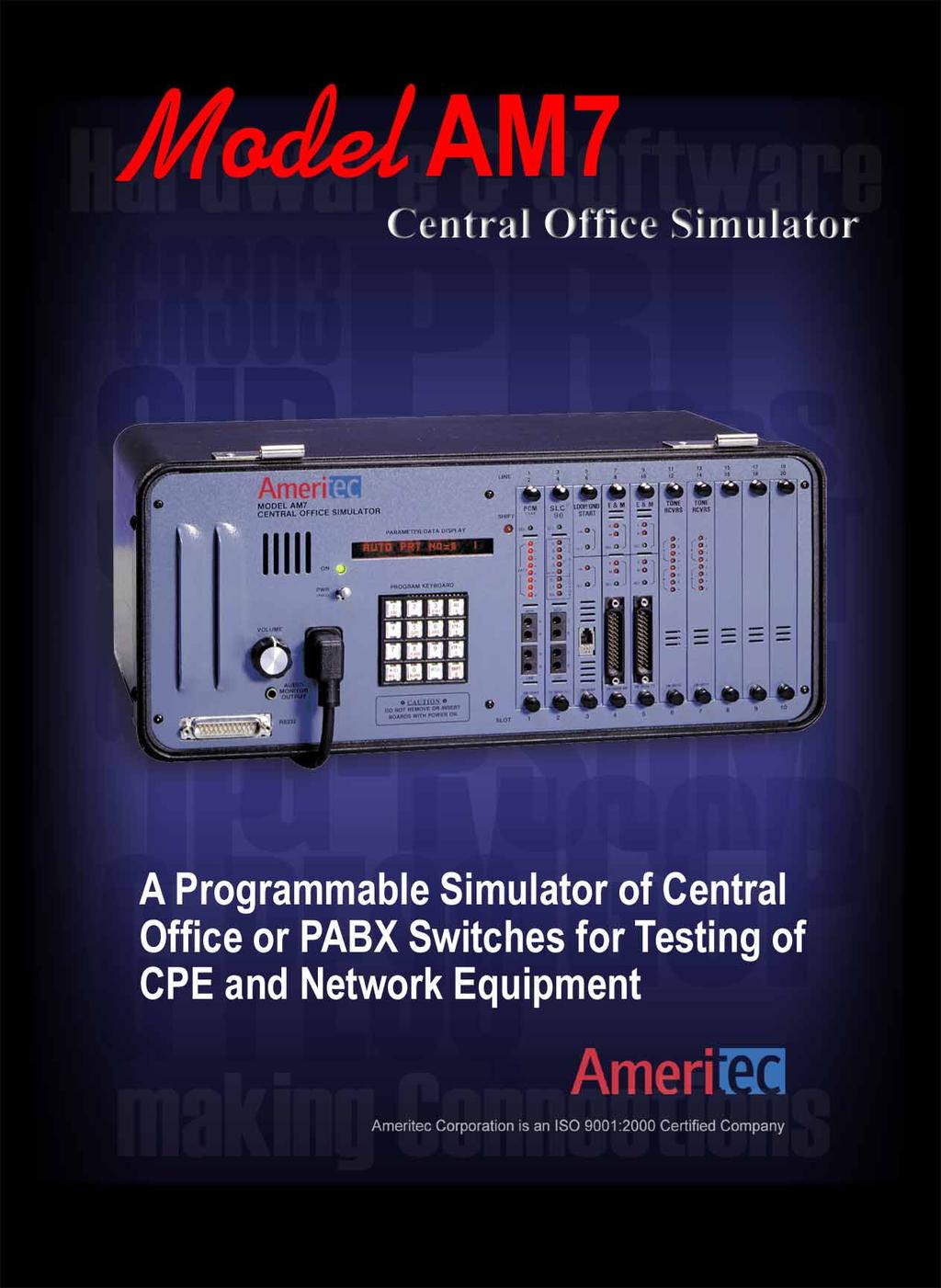
2 Introduction The Ameritec Model AM7 CO Simulator is capable of simulating many of the functions of Central Office switches, PABX switches or the Public Switched Telephone Network (PSTN). The AM7 is user programmable, allowing realistic testing when an actual switch is not available. The AM7 mainframe is a miniature, high performance, non-blocking digital switch. It is capable of switching up to 48,000 calls per hour, and has 10 option card slots for installation of plug-in interfaces. Interface options include Analog Loop/Ground Start, 2- or 4-wire E&M, 1.544Mbps T1 and 1.544Mbps SLC 96 linecards. Line card types can be mixed in the same unit to simulate multiple switch interfaces. The AM7 can detect pulse, DTMF or MF R1 signaling, and can establish a switched connection to any other line in the unit. All call progress tones and cadences are programmable, to produce dialtone, ring, ringback, busy tones, winks, etc. The AM7 can simulate Special Information Tones, circuit congestion conditions, such as line or trunk busy, and can introduce programable switched connection loss. The AM7 includes a powerful dialing analyzer for analyzing received digits. Optional Tone Receiver cards are available for decoding MF and DTMF digits for use with T1 or SLC 96 interfaces. The AM7 is a self-contained, compact, lightweight unit which is easily hand carried, or can be rack mounted for laboratory use. AM7 Central Office Simulator with option boards


3 Applications The AM7 is easily configured to simulate a variety of CO or PABX switches. This allows testing to be performed in development or manufacturing environments where a real switch is not available, or it is too costly, risky or limiting to use lines connected to a live switch. The Analog line interface options for the AM7 make it perfect for testing of Customer Premises Equipment (CPE), particularly in development, manufacturing and repair areas. The T1 line interface option allows testing of CPE or switching equipment with T1 interfaces, and when used in combination with Analog linecards, allows the AM7 to simulate the subscriber and trunk functions of a switch. The SLC 96 option allows the AM7 to fully simulate a COT, making the AM7 perfect for installation testing of SLC 96 Remote Terminals (RTs). The portability of the AM7 allows use in the field to test or install CPE or other equipment. The ability to remote control the AM7 via a built in RS232 port makes it suitable for automated test applications in the laboratory. Interface Options The AM7 has 10 card slots for installation of options. Various mixes of options are possible, up to the 10 slot maximum: 1-10 Dual Line Analog Loop/Ground Start linecards 1-10 Dual Line Analog E&M linecards 1-4 Single Line T1 PCM linecards and/or Single Line SLC 96 linecards 1-7 Tone Receiver Cards

4 Flexible Numbering Plan The AM7 can be programmed with a numbering plan in the same way as a Central Office or PABX switch. The numbering plan defines what received digits the switch should match, and the action the switch should take when a match is made. The numbering plan is implemented with Dialing Codes which define the response of the AM7 to received dialed digits. Four different Dialing Code Groups can be programmed into the unit. For each Dialing Code Group up to 8 Expected Digit fields can be programmed. Each Expected Digit field can hold up to 12 digits. The Expected Digit Field can be programmed to match DTMF or MF digits, any digit, hook flashes, or perform an Automatic Sequence ( Auto Code ). User programmed Dial Code Groups can be saved in up to four storage memories which retain the complete AM7 configuration, even with power removed. Programmable Actions For each Expected Digit Field, there are 8 user programmable Action Codes which define what the AM7 should do in response to the received digits. The actions are: Wait for 1-99 seconds Ringback tone for 1-99 seconds Reorder tone for 1-99 seconds Busy tone for 1-99 seconds Dial tone for 1-99 seconds Dial tone until digit received Confirming tone for 1-99 seconds Digital Milliwatt for 1-99 seconds Setup call to specific outgoing port Setup call to outgoing port in hunt group Generate a Wink Provide Answer Supervision Remove Answer Supervision Send 400Hz tone for 1-99 seconds Send 400Hz tone until digit received Send selected SIT tones Ignore Dialed Digits Accept Dialed Digits Release PCM Tone Receiver Release Tone Analyzer Release Dial Pulse Analyzer Attach PCM Tone Receiver AM7 Central Office Simulator
5 Configurable System Most operational parameters of the AM7 are user configurable to enable faithful emulation of almost any switch. The AM7 System/Unit Parameters control the following for the entire system: Real Time Clock/Calendar Setting Automatic Hourly Printout Yes/No Ring Generator Characteristics Dial Tone Characteristics Ringback Tone Characteristics Line Busy Tone Characteristics Reorder Tone Characteristics Tone Dial Analyzer Operation Dial Pulse Analyzer Operation Report Unexpected Data Link Messages (SLC 96) Yes/No PCM Master Span Selection Receiver Card Signaling Type Connection Loss (0 to 14dB) Printer/RS232 Configuration Software Version Display User Defined Call Progress Signals The AM7 allows the user to completely configure the call progress signals generated. Configuration of the following is provided: Continuous/Interrupted Dial Tone Dial Tone Cadence Dial Tone Level/Frequency Ring Cadence Ring Frequency Ringback Tone Cadence Ringback Level/Frequency Line Busy Tone Cadence Line Busy Level/Frequency Reorder Tone Cadence Reorder Level/Frequency Individual Line Configuration Each line of the AM7 system can be independently configured with the following parameters: SLC 96 Start Mode: Single Party/Loop Start or Universal Voice Grade/Ground Start (Mode I only) SLC 96 Trunk Assign Delay 0-99 sec. Dial Tone/Start Delay 0-99 seconds Auto Code (execute programmed sequence of actions) Confirming Tone Frequency (13) Hunt Group Assignment (1-8) Answer Supervision Yes/No Dial Code Group/Numbering Plan (4) Dial Code Report Yes/No Progress Tone Levels Normal/Low Decode Tone, Pulse or Both Minimum Flash Time ( mS) Minimum Disconnect Time ( mS) Wink Time (50-950mS) Display of Call Activity Registers (Call Attempts, Calls Matching Code, Calls Matching no Code) LINE PARAMETERS 08:09 09/12/94 LINE 101 EMULATION: E&M UNIT PARAMETERS 08:07 09/12/94 START MODE: WINK AUTOMATIC DATA READOUT: ENABLED START (DIAL TONE) DELAY: 00 DIAL TONE AUTOCODE: DISABLED CONTINUOUS CONFIRMING TONE: 0, (1010 HZ) TONE A: -13dBm-0350Hz, TONE B :-13dBm-0440Hz HUNT GROUP: 1 RING ANSWER SUPERVISION: ENABLED FREQUENCY: 20.0Hz DIALLING CODE GROUP: A CADENCE: , ms DIALLING CODE ERROR REPORT: ENABLED RINGBACK CALL PROGRESS TONE LEVEL: NORMAL CADENCE: , ms DIALLING ACCEPTED: PULSE TONE (MF) TONE A: -19dBm-0440Hz, TONE B :-19dBm-0480Hz EVENT RECOGNITION TIMES: A LINE BUSY DISCONNECT: 1000ms, FLASH: 0450msCADENCE: , ms TONE A: -24dBm-0480Hz, TONE B :-24dBm-0620Hz REORDER CADENCE: , ms LINE PARAMETERS 08:08 09/12/94 TONE A: -24dBm-0480Hz, TONE B :-24dBm-0620Hz LINE 003 TONE DIAL ANALYZER: ENABLED START (DIAL TONE) DELAY: 00 LEVEL LIMITS, LOW FREQ: -18:-06dBm, HIGH FREQ: -18:-06dBm AUTOCODE: DISABLED TWIST LIMITS, -06:+06 db, FREQUENCY VARIATION: 01.5% CONFIRMING TONE: C, (0900 HZ) MINIMUM ON-OFF TIMES: 35-35ms, GUARD TIME: 20ms HUNT GROUP: 1 FIXED TO LINE 003, ALL EVENTS ANSWER SUPERVISION: ENABLED DIAL PULSE ANALYZER: ENABLED DIALLING CODE GROUP: A SPEED LIMITS: 08-12PPS, BREAK LIMITS: 50-70% DIALLING CODE ERROR REPORT: ENABLED MINIMUM INTERDIGIT TIME: 0400 CALL PROGRESS TONE LEVEL: NORMAL RANDOMLY ASSIGNED, ALL EVENTS DIALLING ACCEPTED: PULSE TONE CONNECTION LOSS: 06dB EVENT RECOGNITION TIMES: MASTER SPAN: 0 DISCONNECT: 1000ms, FLASH: 0450ms TONE RECEIVER MODES WINK DURATION: 0250ms SLOT 10 TT,MF LINE ATT CODE1 CODE2 CODE3 CODE4 BAUD RATE: 9600, PARITY IS EVEN CLOC ; Unit and Line Parameter Printouts
6 Dialing Analyzers The AM7 features a comprehensive digit analyzer, which produces detailed statistics and errors related to tone and pulse dialing. The Dialing Analyzer Reports are output to the RS232 port for printing, display on a terminal, or capture by a computer. The user configurable parameters for the dialing analyzers are: Tone Dialing Analyzer: Tone Dialing Report Yes/No Low Tone Min./Max. Level High Tone Min./Max. Level Twist, Maximum +, - Frequency Offset, Maximum Tone Minimum On/Off Time Tone Guard Time Random or Fixed Line Selection All Digits/Out of Range Digits Pulse Dialing Analyzer: Dial Pulse Report Yes/No Pulse Min./Max. Speed Pulse Min./Max. Percent Break Pulse Minimum Interdigit Time Random or Fixed Line Selection All Digits/Out of Range Digits MF DIAL REPORT 08:35 09/12/94 LINE ALL DIGITS LOW-BAND HIGH-BAND TWST OFF ON FREQ DEV LEVEL FREQ DEV LEVEL TIME TIME (Hz) (%) (dbm) (Hz) (%) (dbm) (db) (ms) (ms) * PULSE DIAL REPORT : /12/ LINE ALL DIGITS # SPEED BREAK ID-TIME % 635mS % 600mS TT DIAL REPORT 08:10 09/12/ % 600mS LINE ALL DIGITS % 600mS LOW-BAND HIGH-BAND TWST OFF ON FREQ DEV LEVEL FREQ DEV LEVEL TIME TIME (Hz) (%) (dbm) (Hz) (%) (dbm) (db) (ms) (ms) * -24* Dialing Analyzer Reports Reports The AM7 produces a variety of reports which are presented via the RS232 port. Unit Data Registers can be output automatically on the hour: Unit Power On/Off Report Data Readout Report (per-line Call Activity Registers): - Call Attempts - MFR1 Decoder Overflows - DTMF Decoder Overflows - For Each SLC /T1 Line: - Bipolar Violations - Frame Slips - Frame Errors - CRC Errors/SLC Alarms Dialing Code Error Report Tone Dialing Analyzer Report Dial Pulse Analyzer Report Power Recovery after Failure In addition to automatic reports, there are five reports which can be requested by the user: Report Selected Setup Parameters Report All Setup Parameters Report All Data Registers for each line Report Dialing codes for all lines Report Data for Selected lines SPCL FUNCTION 1;3; DATA READOUT 08:36 09/12/94 LINE ATT CODE1 CODE2 CODE3 CODE4 CODE5 CODE6 CODE7 CODE8 NOCODE TOTL DATA READOUT 08:36 09/12/94 SPAN: 1 BPV= SLIP= FERR= CRC= LINE ATT CODE1 CODE2 CODE3 CODE4 CODE5 CODE6 CODE7 CODE8 NOCODE TOTL TONE RECEIVER TRAFFIC DATA RECEIVER OVERFLOWS: MF= TT= ALL RECEIVERS BUSY USAGE SLOT Data Register Report

7 Viewable Data Registers Several data registers can be viewed on the built-in display while the AM7 is running: Real Time Clock Software Version Digit Decoder Overflows SLC /T1 Line Error Counters Per Line Set-Up Parameters Per-line Data Registers: Same as Report registers described above Unit error registers can also be viewed: Per T1 or SLC Line: BPV, Slip, Frame Error and CRC Error/SLC Alarm Counters Portable The AM7 is a compact, self-contained, light weight and easily transported unit. It can optionally be rack mounted for laboratory or factory floor use. AM7 Accessories Remote Control/Chaining The AM7 has an industry standard RS232 interface which can be used to remotely control the unit and/or for output of reports. The AM7 can be controlled by a terminal or computer. All functions that are available from the front-panel user interface are available from the remote control port. Also included is an on-line Help facility for quick reference. Fifteen AM7 units can be chained together and controlled from a single RS232 device. Accessories and Options Line Modules: Field installable line interface modules (maximum of 10 per AM7 unit): Order No. Description Loop/Ground Start Analog lines TT 2 2W/4W E&M DTMF/Pulse Trunks MF 2 2W/4W E&M MFR1/Pulse Trunks Mbps T-1 Line DLC Mbps SLC 96 Line DTMF/MF Tone Receiver Card 5-Ringer Equivalent Option: Option for module to allow operation with up to 5REN loads (standard is 2REN). P/N Transit Case: A transit case is available for secure commercial transportation of one or two units, complete with cables and instruction manuals. P/N Rack Mounting Kit: The AM7 can be rack mounted in standard 19 racks with an optional rack mount kit. P/N Spare Card Carrying Case: Used to store up to 20 line card modules. P/N

8 AM7 CO Simulator Specifications SYSTEM Capacity: 10 option card slots. Each slot can accommodate any of the following: Line Cards: Analog: 2 loop/ground start lines Analog: 2 E&M lines types I,II,III,IV,V T1: One span (max. 4 x SLC 96 or T1) SLC 96: One span Tone Decoders (max. of 7 per unit): DTMF: 6 TT decoders MFR1: 8 MFR1 decoders Simultaneous Calls: Non-Blocking switching for any combination of connections. Busy Hour Call Volume: Up to 48,000 calls/hour Chaining: Up to 15 AM1/AM7 units may be chained and controlled via RS232 interface or print to a serial printer. Signaling Systems: Analog: Loop Start or Ground Start. T1:E&M, Wink Start, Delay Dial, Dial Tone Start, Immediate Start, Loop Start, Ground Start, ESF. SLC 96: Universal Voice Grade (Mode I) and Single Party (Modes I and II). Complies with Bellcore TR-TSY Dialing: Dial pulse, DTMF, or MFR1. Dialing Codes: 4 groups of 8 for each line DETECTORS Analog Loop/Ground Start: Loop current, Ring trip, Ring ground, per line DTMF decoder Analog E&M: E Lead, per line DTMF/MFR1 decoder T1/SLC : A/B signaling bits, per channel dial pulse decoder, optional shared DTMF/MFR1 digit decoders DIGIT DECODERS DTMF On/Off Time: 40mS min. Twist: +/- 9dB Frequency Variation: +/- 1.5% accept, +/- 3.5% reject Level: 0dBm to -24dBm per tone (40mS On/Off, 0dB Twist, 0Hz Frequency Variation), 0dBm to -6dBm per tone (40mS On/Off, +/- 9bB Twist, +/- 1.5% Frequency Variation) MF(R1) KP Digit On/Off Time: 55/20mS accept, 30/10mS reject All Other Digits: 30/20mS accept, 10/10mS reject Twist: +/- 6dB max. Frequency Variation: +/- 1.5% Level: 0dBm to -25dBm per tone Dial Pulse Max. Speed: 80% break; 40% break; 50% break Min. Speed: 80% break; 40% break; 50% break Break: 5pps; 10pps; 25pps Min. Interdigit Timing: 5pps, 60% break; 60% break; 25pps, 60% break DIGIT ANALYZER Tone Dialing: TMS320 DSP measures level, frequency, on/off timing, Twist and Skew of DTMF or MF(R1) digits Pulse Dialing: Speed, % break, interdigit timing TONE GENERATORS Call Progress Tones Dial Tone Cadence: On/Off times from mS Dial Tone Level: -3dBm to -39dBm in 1dBm steps, for each tone, including Quiet Dial Tone Frequency: 200Hz to 3500Hz in 10Hz steps, programmable for each tone Ring Frequency: Hz in 0.1Hz steps Ring Cadence: 2 ringing sequences (Ring 1 and Ring 2). Ring 1 programmable from mS in 100mS steps. Ring 2 programmable from mS in 100mS steps Ringback Tone Cadence: 2 ringback sequences (Ringback 1 and Ringback 2). Ringback 1 programmable from mS in 100mS steps. Ringback 2 programmable from mS in 100mS steps Ringback Level: -3dBm to -39dBm in 1dB steps, for each tone, including Quiet Ringback Frequency: 200Hz to 3500Hz in 10Hz steps, programmable for each tone Line Busy Tone Cadence: 2 line busy sequences (Line Busy 1 and Line Busy 2). Line Busy 1 programmable from mS in 100mS steps. Line Busy 2 programmable from mS in 100mS steps Line Busy Level: -3dBm to -39dBm in 1dB steps, programmable for each tone, including Quiet Line Busy Frequency: 200Hz to 3500Hz in 10Hz steps, for each tone, including Quiet Reorder Tone Cadence: 2 reorder sequences (Reorder 1 and Reorder 2). Reorder 1 programmable from mS in 100mS steps. Reorder 2 programmable from mS in 100mS steps Reorder Tone Level: -3dBm to -39dBm in 1dB steps, for each tone, including Quiet Reorder Frequency: 200Hz to 3500Hz in 10Hz steps, programmable for each tone Confirming Tones Any line can generate one of the following single tones at -6dBm as part of a Step Sequence: 900Hz, 1010Hz, 1150Hz, 1280Hz, 1400Hz, 1530Hz, 1650Hz, 1780Hz, 1900Hz, 2030Hz, 2150Hz, 2280Hz, 2400Hz SIT Tones Any line can generate one of the following 6 SIT tones at -6dBm as part of an Action Sequence: Vacant Code (980/1370/1780Hz), No Circuit-BOC (980/1430/1780Hz), Intercept (910/1370/1780Hz), Reorder-BOC (910/1430/1780Hz), Reorder-Carrier (980/1370/1780), No Circuit-Carrier (910/1370/1780Hz) SIGNAL/POWER SOURCES Loop Voltage (2W Analog): -48V DC +5% open circuit Ring Generator: Sine wave, variable Hz. 60Vrms open circuit, 40Vrms with 2REN load MISCELLANEOUS Frequency Response: Less than 0.7dB attenuation distortion from 300Hz to 3300Hz Connection Loss: Programmable from 0dB to 14dB in 1dB steps T1/SLC Interfaces: Bantam connectors for each span. 8kHz Clock Source: internal 8kHz reference or span 1-4 User Interface: 16 button keypad, 16 digit alphanumeric LED display RS232C/V.24 Port: Serial, asynchronous, ASCII code at baud, Odd or Even parity, 7 Data Bits, 2 Stop Bits, full duplex on 3 wires (DB25P) Audio Monitor: Built in monitor and loudspeaker Non-Volatile Memory: 4 non-volatile memory sets for numbers and parameters. Active parameters are saved with power removed for up to 30 days. POWER VAC, 50/60Hz, or VAC, 50/60Hz., 50W max. DIMENSIONS Compact and Portable Dimensions: 16.8 L x 7.2 W x 11.5 H Weight: 18 lb. SLC is a registered trademark of AT&T All specifications subject to change without notice
TSA 6000 System Features Summary
 2006-03-01 1. TSA 6000 Introduction... 2 1.1 TSA 6000 Overview... 2 1.2 TSA 6000 Base System... 2 1.3 TSA 6000 Software Options... 2 1.4 TSA 6000 Hardware Options... 2 2. TSA 6000 Hardware... 3 2.1 Signal
TLS-3A. Telephone Line Simulator. User Manual , Rev. B Covers Model TLS-3A-01
 User Manual TLS-3A Telephone Line Simulator 40-400-00010, Rev. B Covers Model TLS-3A-01 Teltone Corporation 22121-20th Avenue SE Bothell, Washington 98021-4408 USA Phone: 1-800-426-3926 or 425-487-1515
Sage Instruments 935AT. Test Options Guide
 Sage Instruments 935AT Test Options Guide Last Updated 20 February 2001 Table of Contents 935AT Applications... 3 Transmission... 3 Signaling and Supervision... 3 Trunks... 3 Digits... 3 Emulation... 3
MODEL 640 DAPT XTRA. Dial Access Paging Terminals for Display and Voice Pagers
 MODEL 640 DAPT XTRA Dial Access Paging Terminals for Display and Voice Pagers FEATURES Paging 1,500 subscriber capacity 280 seconds of pooled voice storage Supports all popular analog and digital paging
Part IV: Glossary of Terms
 Issue 9 November 2004 Spectrum Management and Telecommunications Policy Compliance Specification for Terminal Equipment, Terminal Systems, Network Protection Devices, Connection Arrangements and Hearing
ZLS38503 Firmware for Voice Prompting and Messaging Firmware Manual
 ZLS38503 Firmware for Voice Prompting and Messaging Firmware Manual Features Voice recording (messaging) and playback (voice prompting) DTMF receiver Tone Generator (preprogrammed DTMF + user defined tones)
VC-6 6-Channel PCM Voice Module MEGAPLEX-2100 MODULE
 Installation and Operation Manual VC-6 6-Channel PCM Voice Module MEGAPLEX-2100 MODULE MEGAPLEX-2100 MODULE VC-6 6-Channel PCM Voice Module Installation and Operation Manual Notice This manual contains
!!!!!!!!!!!!!!!!!!!!!!!!!!!!!!!!!!!!!!!!!!!!!!!"
 !!!!!!!!!!!!!!!!!!!!!!!!!!!!!!!!!!!!!!!!!!!!!!!" A624 Feature / Programming Overview The A624 has many new and changed features compared with the 30810 / 61610 This Guide is intended to assist installers
Figure FXS Front Panel. Figure FXS Front Panel
 Telecommunications Group Section 365-780-202 Equipment Issue 2 Fifth Printing, October 2006 12-Channel (3657-80) and 6-Channel (3657-81) 2-Wire Foreign Exchange Subscriber, Private Line Automatic Ringdown
VC-4/4A, VC-8/8A, VC-16 4/8/16-Channel PCM and ADPCM Voice Modules
 4, 8 or 16 analog voice channels using 64 kbps toll-quality PCM encoding; 24/32 kbps ADPCM encoding option for 4- and 8-channel modules E&M, FXS or FXO interface options Caller ID A-law or μ-law companding
VC-4/4A, VC-8/8A, VC-16
 Data Sheet Megaplex-4, Megaplex-2100/2104 VC-4/4A, VC-8/8A, VC-16 E&M, FXS or FXO options Caller ID A-law or µ-law companding Optional inband signaling with A-law encoded channels PCM (64 kbps) and ADPCM
Installation and Operation Manual VC-6A. 6-Channel PCM/ADPCM Voice Module MEGAPLEX-2100 MODULE
 Installation and Operation Manual VC-6A 6-Channel PCM/ADPCM Voice Module MEGAPLEX-2100 MODULE VC-6A 6-Channel PCM/ADPCM Voice Module Installation and Operation Manual Notice This manual contains information
Call Progress Tone and Ringing Signal Generation
 Exercise 1-3 Call Progress Tone and Ringing Signal Generation EXERCISE OBJECTIVE When you have completed this exercise, you will be familiar with call progress tone and ringing signal generation. DISCUSSION
Appendix C T1 Overview
 Appendix C T Overview GENERAL T refers to the primary digital telephone carrier system used in North America. T is one line type of the PCM T-carrier hierarchy listed in Table C-. T describes the cabling,
DIGITAL LINK MEASURING INSTRUMENTS MS371A/A1 GPIB PCM CHANNEL ANALYZER. For Simultaneous Measurement of 30 Channels with MS120A
 PCM CHANNEL ANALYZER MS371A/A1 For Simultaneous Measurement of 30 Channels with MS120A (MS371A1) GPIB The MS371A/A1 is an overall measuring instrument with many measuring functions for digital primary
Part VI: Requirements for Integrated Services Digital Network Terminal Equipment
 Issue 9, Amendment 1 September 2012 Spectrum Management and Telecommunications Compliance Specification for Terminal Equipment, Terminal Systems, Network Protection Devices, Connection Arrangements and
Mastr III P25 Base Station Transmitter Tune-up Procedure
 Mastr III P25 Base Station Transmitter Tune-up Procedure 1. Overview The Mastr III Base Station transmitter alignment is performed in several steps. First, the Transmit Synthesizer module is aligned to
- 1 - Rep. ITU-R M.2009 REPORT ITU-R M.2009 DIRECT-DIAL TELEPHONE SYSTEMS FOR THE MARITIME MOBILE SERVICE
 - 1 - REPORT ITU-R M.2009 DIRECT-DIAL TELEPHONE SYSTEMS FOR THE MARITIME MOBILE SERVICE (1995) General Although the DSC system may be used to establish fully automatic systems in the directions ship-to-shore,
Part VI: Requirements for ISDN Terminal Equipment
 Issue 9 November 2004 Spectrum Management and Telecommunications Policy Compliance Specification for Terminal Equipment, Terminal Systems, Network Protection Devices, Connection Arrangements and Hearing
USER'S MANUAL. Model : K
 USER'S MANUAL Model : 2000-64K TM GINA MODEL 2000-64K Overview GINA Model 2000-64K is a stand-alone, high frequency data transceiver using spread spectrum technology. GINA 2000-64K capabilities include
SOLUTIONS FOR AN EVOLVING WORLD RFL DSP Powerline Carrier System
 SOLUTIONS FOR AN EVOLVING WORLD RFL 9508 DSP Powerline Carrier System Your world is changing and so are we. At RFL, we know your needs change much faster than your infrastructure. Our comprehensive line
AM48 XT & AM48e XT Family of Products
 AM48 XT & AM48e XT Family of Products AM-44 XT The AM-4 Series of Hand-Held Transmission Test Sets There are four models in the AM-4 series family. They are AM-44 XT and AM-48 XT which comply with Bell
MicroFox2 Manual. Version 0.5 August 28, 2017
 Overview The Byonics MicroFox2 (MF2) is a small, 500mW, frequency agile 2-meter transceiver designed for hidden transmitter hunts, also called T-hunts, foxhunts, and ARDF. It is based on the Byonics MicroFox-PicCon,
Faculty of Engineering Electrical Engineering Department Communication Engineering I Lab (EELE 3170) Eng. Adam M. Hammad
 Eng. Adam M. Hammad") Faculty of Engineering Electrical Engineering Department Communication Engineering I Lab (EELE 3170) Eng. Adam M. Hammad EXPERIMENT #2 UNDERSTANDING TELEPHONE BASICS Telephone components: 1. Handset containing
Faculty of Engineering Electrical Engineering Department Communication Engineering I Lab (EELE 3170) Eng. Adam M. Hammad EXPERIMENT #2 UNDERSTANDING TELEPHONE BASICS Telephone components: 1. Handset containing
TACT TA-4800T RACK MOUNT / DESK-TOP VERSION ACMA SUPPLIER S CODE N468 NEW ZEALAND TELEPERMIT PTC 210/96/003 USER HANDBOOK. Issue 6, OCTOBER, 2008
 TACT TA-4800T TRUNKED TWO-WAY RADIO / TELEPHONE INTERCONNECT RACK MOUNT / DESK-TOP VERSION ACMA SUPPLIER S CODE N468 NEW ZEALAND TELEPERMIT PTC 210/96/003 USER HANDBOOK, OCTOBER, 2008 DESIGNED AND MANUFACTURED
GDC 086R Issue 4, 10/17/97. Installation and Operation. Metroplex Flexi-Voice Plus Model MP General DataComm
 GDC 086R603-001-04 Issue 4, 10/17/97 Installation and Operation Metroplex 6000 Flexi-Voice Plus Model MP 6360 General DataComm Manual Revision History Shown below is a chronological listing of revisions
Technical Equipment Specification
 STATE OF CALIFORNIA Office of the State Chief Information Officer Public Safety Communications Division Technical Equipment Specification Equipment Type: Transmitter/Receiver Mobile Relay/Base/Control
khz to 2.9 GHz Spectrum Analyzer
 Spectrum Analyzers 2399 9 khz to 2.9 GHz Spectrum Analyzer A spectrum analyzer with outstanding performance and a user friendly visual interface simplifying many complex measurements. 9 khz to 2.9 GHz
MultiMaster. Base Station Test Tools. Multi Purpose Base Station Tester. Introduction. Feature
 Introduction The GenComm is a comprehensive and cost effective solution for performing base station and repeater maintenance in any environment covering all CDMA Standards including cdmaone, cdma2000 1x
TACT TA-4700 IC/SMR AND PSTN INTERCONNECT OPERATOR MANUAL. Issue 7, JULY, 2006, AUTHOR: PETER ZEUG. Est ACA SUPPLIER S CODE NUMBER N468
 TACT TM TA-4700 IC/SMR AND PSTN INTERCONNECT RACK MOUT VERSION SERIAL/ITEM 533/nnn OPERATOR MANUAL Issue 7, JULY, 2006, AUTHOR: PETER ZEUG DESIGNED AND MANUFACTURED IN AUSTRALIA Est. 1968 DESIGN TWO THOUSAND
Agilent 8920A RF Communications Test Set Product Overview
 Agilent 8920A RF Communications Test Set Product Overview Cut through problems faster! The Agilent Technologies 8920A RF communications test set was designed to solve your radio testing and troubleshooting
MEGAPLEX-2100 MODULE VC-16A. 16-Channel PCM/ADPCM Voice Module Installation and Operation Manual. Notice
 MEGAPLEX-2100 MODULE VC-1A 1-Channel PCM/ADPCM Voice Module Installation and Operation Manual Notice This manual contains information that is proprietary to RAD Data Communications No part of this publication
USER MANUAL G703FTEC. T1/E1 Cross Rate Converter
 USER MANUAL G703FTEC T1/E1 Cross Rate Converter CTC Union Technologies Co., Ltd. Far Eastern ViennaTechnology Center (Neihu Technology Park) 8F, No. 60 Zhouzi St. Neihu Taipei 114, Taiwan G703-FTEC T1/E1
This document is designed to be used in conjunction with the CMX869A data sheet.
 CML Microcircuits COMMUICATIO SEMICODUCTORS Publication: A/Telecom/869A/1 May 2006 Application ote Bell 212A Implementation with CMX869A 1 Introduction The Bell 212A data communications protocol, originally
Spectrum Analyzers. 2394A 1 khz to 13.2 GHz Spectrum Analyzer.
 Spectrum Analyzers 2394A 1 khz to 13.2 GHz Spectrum Analyzer A spectrum analyzer with outstanding performance and a user friendly visual interface simplifying many complex measurements 1 khz to 13.2 GHz
5 yr. Station Level Paging Adapter. Model 300PBX-SC LINKS TELEPHONE TO SELECTONE OR PUBLIC ADDRESS SYSTEM. dedicated extension
 FEDERAL SIGNAL CORPORATION Station Level Paging Adapter Model 300PBX-SC LINKS TELEPHONE TO SELECTONE OR PUBLIC ADDRESS SYSTEM Paging by calling a dedicated extension Powered by a phone line connection
Technical Data. Digital FDM Demultiplexer WJ-9548 & WJ WATKINS-JOHNSON. Features
 May 1997 Technical Data WATKINS-JOHNSON Digital FDM Demultiplexer WJ-9548 & WJ-9548-1 The WJ-9548 Digital FDM Demultiplexer is a compact, multichannel demodulator that incorporates the accuracy and repeatability
TACT TA-4800 RACK MOUNT VERSION USER HANDBOOK. Issue 2, Dec, 2009 ACMA SUPPLIER S CODE N468 NEW ZEALAND TELEPERMIT PTC 210/96/003
 TACT TA-4800 MAN ALONE PERSONAL SAFETY ALARM RADIO / TELEPHONE INTERCONNECT RACK MOUNT VERSION USER HANDBOOK Issue 2, Dec, 2009 ACMA SUPPLIER S CODE N468 NEW ZEALAND TELEPERMIT PTC 210/96/003 DESIGNED
ADDENDUM 1. Bid# , Radio Interoperability System for the Sheriff's Office
 County of El Paso Purchasing Department 500 East San Antonio, Room 500 El Paso, Texas 79901 (915) 546-2048 / Fax: (915) 546-8180 ADDENDUM 1 To: From: All Interested Proposers Claudia Sepulveda, Bid Clerk/Buyer
 Options and their applications Extensions for basic model OCXO Reference Oscillator For long-term stability OCXO Reference Oscillator For extremely high long-term stability Duplex Modulation Meter Allows
PSTN MEASUREMENT REPORT
 Page 1 of 25 PSTN MEASUREMENT REPORT Report No.: TS11010101-TEL Model No.: APCTEL002 Report Issued Date: Feb. 01, 2011 Applicant: American Power Conversion Holdings Inc. 3F, No. 205, Sec. 3, Beishin Rd.,
Far End Device II Model 1342
 3 Far End Device II Model 1342 Operating Instructions Optimized for ADSL2+ May 2007 78-8130-0876-6-C Table of Contents Introduction...3 Power-up...4 Connecting the 3M Far End Device II...5 Installing,
MAINTENANCE MANUAL FOR CONVENTIONAL NETWORK INTERFACE
 C MAINTENANCE MANUAL FOR CONVENTIONAL NETWORK INTERFACE TABLE OF CONTENTS Page SPECIFICATIONS................................................ 1 INTRODUCTION.................................................
M-980 General Purpose Call Progress Tone Detector
 General Purpose Call Progress Tone Detector The Teltone M-980 is an integrated circuit tone detector for general purpose use in automatic following of switched telephone calls. The circuit uses low-power
Interface converter G kbit/sec
 converter User s Guide 12345678901234567890123456789012123456789012345678901234567890121234567890123456789012345678901212345678901 Interface converter G.703.1 64 kbit/sec Features Maximum line attenuation
Advanced Test Equipment Rentals ATEC (2832)
") Established 1981 Advanced Test Equipment Rentals www.atecorp.com 800-404-ATEC (2832) 50-15217-01 Rev. D T-BERD 2207 USER S GUIDE This manual applies to all T-BERD 2207 software incorporating software level
Established 1981 Advanced Test Equipment Rentals www.atecorp.com 800-404-ATEC (2832) 50-15217-01 Rev. D T-BERD 2207 USER S GUIDE This manual applies to all T-BERD 2207 software incorporating software level
MODEL CM-30. Technical Practice November 2002 Issue 4. Service Observing System 1. GENERAL 2. DESIGN FEATURES CONTENTS: Model CM-30
 Model CM-30 Technical Practice November 2002 Issue 4 MODEL CM-30 Service Observing System 1. GENERAL 1.01 The DEES CM-30 is a complete 30 line service observing system with integrated talk assist capability.
Wilcom MODEL T336B CIRCUIT TEST SET. Operating Instructions
 Wilcom MODEL T336B CIRCUIT TEST SET Operating Instructions T336B Circuit Test Set Operating Instructions 810-311-007 June 2005 Copyright (c) 2005 Wilcom All Rights reserved Wilcom reserves the right to
Contents 1. FEATURES EQUIPMENT DESCRIPTION INSTALLATION OPERATION TROUBLESHOOTING SPECIFICATIONS...
 Contents 1. FEATURES... 3 2. EQUIPMENT DESCRIPTION... 3 3. INSTALLATION... 5 4. OPERATION... 5 5. TROUBLESHOOTING... 7 6. SPECIFICATIONS... 8 2 1. FEATURES Telephone Foreign Exchange Subscriber (FXS) Service:
3M Dynatel Far-End Device (FED II) Applications
 Applications") Testing with the 965DSP and Far-End-Device () The is like having a helper at the far end of the pair while you are performing AUTO tests with the 965DSP. It can qualify new lines or identify service problems
Testing with the 965DSP and Far-End-Device () The is like having a helper at the far end of the pair while you are performing AUTO tests with the 965DSP. It can qualify new lines or identify service problems
Intelligent peripheral equipment circuit cards for New Zealand
 Meridian 1 Intelligent peripheral equipment circuit cards for New Zealand Option 11 - Description and Installation Document Number: Supplement to 553-3011-210 Document Release: Provisional 1.3 Date: July
OPERATION MANUAL INSTALLATION AND VC-4/OMNI. Omnibus PCM Voice Module. Megaplex-2100/2104 Version 12, Megaplex-4100 Version 1.6. The Access Company
 INSTALLATION AND OPERATION MANUAL VC-4/OMNI Omnibus PCM Voice Module Megaplex-2100/2104 Version 12, Megaplex-4100 Version 1.6 The Access Company VC-4/OMNI Omnibus PCM Voice Module Megaplex-2100/2104 Version
Firmware upgrades with new features are freely available and can be easily downloaded to the LT51 in the field.
 LINE TESTER LT51 The LT51 Line Tester is a portable handheld battery powered instrument. It combines the features of several pieces of test equipment such as a Selective Level Meter / Spectrum Analyser,
MODEL 625A SMARTARB BNC A BEST BUY. Eliminates Phase Jitter
 A BEST BUY The Model 625A SMARTARB was designed to provide more operating modes, more functions and more measurement modes than any other unit in its price class. Further upgrading and additions of these
TECHNICAL. Time and Temperature Announcer DVA-TNT. Time and Temp Announcer
 TECHNICAL Practice TELECOM SOLUTIONS FOR THE 21ST CENTURY DVA-TNT Time and Temp Announcer August 31, 2001 Features Phone...715.386.8861 Time and Temperature Announcer The DVA-TNT Time and Temperature Announcer
VS-900 Security Intercom Systems. Architectural and Engineering Specification
 VS-900 Security Intercom Systems Architectural and Engineering Specification TOA Electronics, Inc. 601 Gateway Blvd., Ste. 300 So. San Francisco, CA 94080 1-650-588-2538 / 1-800-733-4750 V1, All Rights
This is by far the most ideal method, but poses some logistical problems:
 NXU to Help Migrate to New Radio System Purpose This Application Note will describe a method at which NXU Network extension Units can aid in the migration from a legacy radio system to a new, or different
Hytera DMR Conventional Series
 Hytera DMR Conventional Series SIP Phone Gateway to Simultaneous Calls Application Notes Document version: 3.0 Date: 02-2015 Copyright Information Hytera is the trademark or registered trademark of Hytera
Firmware upgrades with new features are freely available and can be easily downloaded to the LT51 in the field.
 LINE TESTER LT51 The LT51 Line Tester is a portable handheld battery powered instrument. It combines the features of several pieces of test equipment such as a Selective Level Meter / Spectrum Analyser,
Subscriber loop. Claude Rigault ENST FCN, 29/09/2002 Claude Rigault, ENST 1
 Subscriber loop Claude Rigault ENST claude.rigault@enst.fr FCN, 29/09/2002 Claude Rigault, ENST 1 FCN, 29/09/2002 Claude Rigault, ENST 2 2-wire / 4-wire Transformation FCN, 29/09/2002 Claude Rigault, ENST
Compliance Requirements Overview 1
 Compliance Requirements Overview The standard two-wire telephone-set connection known as analog PSTN (Public Switched Telephone Network) (loop start) or POTS (Plain Old Telephone Service) is the oldest
The DR-2000 is a high-performance receiver designed to enable highly sophisticated data and signal processing over a wide frequency spectrum.
 The DR-2000 is a high-performance receiver designed to enable highly sophisticated data and signal processing over a wide frequency spectrum. L3 (L3 T&RF) DR-2000 receiving unit incorporates a high-performance
Specification Sheet. MC SERIES Deskset Controllers
 Specification Sheet MC SERIES Deskset Controllers Pictured from left to right are the MC2000 Advanced Model which includes Tone Paging and MDC-1200 signaling, the MC2500 Multi-channel Model, and the MC1000
1. INTEROPERABILITY GATEWAY DEVICES
 1. INTEROPERABILITY GATEWAY DEVICES Category Definition: Devices that interface multiple radios, of multiple makes and models, to analog telephones, to IP telephone networks, and to other devices; allowing
POT Line to Remote Phone
 OPX PO Line to Remote Phone FXO In this application the customer uses the specified ADRAN equipment to extend a plain old analog telephone line to a remote location (Off Premise Extension). he customer
ROM/UDF CPU I/O I/O I/O RAM
 DATA BUSSES INTRODUCTION The avionics systems on aircraft frequently contain general purpose computer components which perform certain processing functions, then relay this information to other systems.
3050 Stereo Power Amplifier
 3050 Stereo Power Amplifier Owners Manual 10/26/2016 Boulder Amplifiers, Inc. 255 Taylor Ave. Louisville, CO 80027 (303) 449-8220 www.boulderamp.com Fault Conditions Boulderlink Appendix Remote Control
Zone Paging System. Model PCM2000. Features. Technical Specifications
 Zone Paging System Model PCM2000 Features One-zone to 99-zones of simultaneous highpower and low-power paging Up to 32 paging zone groups Universal telephone interface designed for direct connection to
Dynatel. 2273M Cable/Pipe and Fault Locators 2273M-iD Cable/Pipe/Fault and Marker Locators with id Read/Write
 3 Dynatel 2273M Cable/Pipe and Fault Locators 2273M-iD Cable/Pipe/Fault and Marker Locators with id Read/Write Designed to be more accurate, faster and more integrated than any other locator on the market,
Shaping the future. ... in FIELD COMMUNICATIONS
 Shaping the future... in FIELD COMMUNICATIONS Integration of Analogue, ISDN and IP/VoIP Terminals Radio Equipment Analogue and Digital Trunks Connectivity to ISDN and IP Networks CD-116/IP Field Digital
2026Q CDMA/GSM Interferer MultiSource Generator
 Signal Sources 2026Q CDMA/GSM Interferer MultiSource Generator The 2026Q is designed to work with a radio test set to provide a fully integrated radio receiver test solution for cellular and PCS systems
GSM-4 (program version 4.02)
") COMMUNICATION MODULE GSM-4 (program version 4.02) OPERATING INSTRUCTION GDAŃSK, POLAND gsm4_e 11/03 WARNING For safety reasons, the module should only be installed by qualified personnel. In order to avoid
COMMUNICATION MODULE GSM-4 (program version 4.02) OPERATING INSTRUCTION GDAŃSK, POLAND gsm4_e 11/03 WARNING For safety reasons, the module should only be installed by qualified personnel. In order to avoid
SNV-12 Voter Quick Reference Help Sheets
 Chassis, Power Supply, and CIM Module SNV-12 Configuration Settings and Adjustments (0=Off, 1=On) Chassis Rear Panel: Designator Factory Setting Switch Choices AC Line Voltage Rear Panel AC Input Module
Application Note Security Industry Protocols with the CMX865A
 CML Microcircuits COMMUNICATION SEMICONDUCTORS Application te Security Industry Protocols with the CMX865A AN/Telecom/CMX865A/1 March 2007 1 Introduction Security alarm panels are used around the world
MOTOTRBO R1.8 Training Overview
 MOTOTRBO R1.8 Training Overview MOTOTRBO System Training Release1.8 MOTOROLA, MOTO, MOTOROLA SOLUTIONS and the Stylized M Logo are trademarks or registered trademarks of Motorola Trademark Holdings, LLC
FREEDOM Communications System Analyzer R8000C DATA SHEET
 FREEDOM Communications System Analyzer R8000C DATA SHEET Table of Contents Operating/Display Modes General 3 3 Generator (Receiver Test) 4 Receiver (Transmitter Test) 5 Spectrum Analyzer 6 Oscilloscope
FREEDOM Communications System Analyzer R8100 DATA SHEET
 FREEDOM Communications System Analyzer R8100 DATA SHEET Table of Contents Operating/Display Modes General 3 3 Generator (Receiver Test) 4 Receiver (Transmitter Test) 5 Spectrum Analyzer 6 Oscilloscope
G-Series Modular Platform Audible and Visual Product Family
 G-Series Modular Platform Audible and Visual Product Family Application Guide for Product Installation and Configuration 0000 Rev: A0 Printed in U.S.A. Table of Contents A. Scope... B. Applicable and/or
Communication Technology DiTEX 256 The wireless access network
 DiTEX 256 The wireless access network Get people connected via radio: Link up with DiTEX 256! DiTEX 256 The wireless access network The classical telephone is typically associated with a long cable from
PTR-1500 AUDIO TONE TELEPROTECTION TERMINAL FEATURES DESCRIPTION
 PTR-1500 AUDIO TONE TELEPROTECTION TERMINAL FEATURES Up to four channels per unit Full on-board programmability Available pilot tone channel Single end manual and automatic testing Modular design Audio
FREEDOM Communications System Analyzer R8000C DATA SHEET
 FREEDOM Communications System Analyzer R8000C DATA SHEET Table of Contents Operating/Display Modes 3 General 3 Generator (Receiver Test) 4 Receiver (Transmitter Test) 5 Spectrum Analyzer 6 Oscilloscope
FREEDOM Communications System Analyzer R8600 DATA SHEET
 FREEDOM Communications System Analyzer R8600 DATA SHEET Table of Contents Operating/Display Modes 3 General 3 Generator (Receiver Test) 4 Receiver (Transmitter Test) 5 Spectrum Analyzer 6 Oscilloscope
Concept of Serial Communication
 Concept of Serial Communication Agenda Serial v.s. Parallel Simplex, Half Duplex, Full Duplex Communication RS-485 Advantage over RS-232 Serial v.s. Parallel Application: How to Measure the temperature
8800SX DMR Repeater Test Option 06
 8800SX DMR Repeater Test Option 06 DMR Repeater Test Option The DMR Repeater test option allows testing of a DMR Repeater that is in conventional DMR Mode. Trunking or analog configurations are not supported.
The RCB-2000 is a compact receiving system that combines two high-performance telemetry RF sections.
 The RCB-2000 is a compact receiving system that combines two high-performance telemetry RF sections. L3 Telemetry& RF products (L3 T&RF) RCB-2000 is a compact, receiving system that combines two high-performance
SOLUTIONS FOR AN EVOLVING WORLD RFL Programmable FSK Powerline carrier system
 SOLUTIONS FOR AN EVOLVING WORLD RFL 9780 Programmable FSK Powerline carrier system Your world is changing and so are we. At RFL, we know your needs change much faster than your infrastructure. Our comprehensive
G1E+ Programming Manual
 G1E+ Programming Manual Hybrid IP Telephone System Rev 2.2d Notification Notification is hereby given that TransTel Communications, Inc. reserves the right to modify, change, update or revise this document
TMR880i technical details
 SCS / Terminals Jan 2013 1(8) TMR880i technical details SCS / Terminals Jan 2013 2(8) TETRA Terminals from CASSIDIAN fulfill the following specifications for TETRA radio equipment in the temperature range
SOUTHERN AVIONICS COMPANY. SE125 Transmitter. SE125 Transmitter 1-1
 1-1 1 Introduction The SE Series transmitters are computer controlled systems designed around an embedded microprocessor. These systems are capable of remote monitoring and maintenance via Ethernet (optional).
Part I: Requirements for Terminal Equipment (TE) and Related Access Arrangements Intended for Direct Connection to Analog Wireline Facilities
 and Related Access Arrangements Intended for Direct Connection to Analog Wireline Facilities") Issue 9, Amendment 5 March 2016 Spectrum Management and Telecommunications Compliance Specification for Terminal Equipment, Terminal Systems, Network Protection Devices, Connection Arrangements and Hearing
Issue 9, Amendment 5 March 2016 Spectrum Management and Telecommunications Compliance Specification for Terminal Equipment, Terminal Systems, Network Protection Devices, Connection Arrangements and Hearing
DSC 3000 CONTROLLER-RECEIVER FOR VHF DSC TECHNICAL MANUAL
 DSC 3000 CONTROLLER-RECEIVER FOR VHF DSC TECHNICAL MANUAL 700 02-96 910 000 72 ISSUE A2 Skandinavisk Teleindustri SKANTI A/S 34, Kirke Værløsevej - DK 3500 Værløse Denmark All information contained in
DSC 9000 SERIES TECHNICAL MANUAL
 DSC 9000 SERIES TECHNICAL MANUAL 500 09-96 910 000 63 Issue A6 Skandinavisk Teleindustri SKANTI A/S 34, Kirke Værløsevej - DK 3500 Værløse Denmark All information contained in the manual including drawings,
Lift communicator USER GUIDE
 Lift communicator USER GUIDE Welcome The Link Lift Watch is designed for emergency call from lift to first aid ( service department, police, etc The LLW is certained for 1 lift cabin. It is connectable
Models 296 and 295 combine sophisticated
 Established 1981 Advanced Test Equipment Rentals www.atecorp.com 800-404-ATEC (2832) Models 296 and 295 50 MS/s Synthesized Multichannel Arbitrary Waveform Generators Up to 4 Independent Channels 10 Standard
FREEDOM Communications System Analyzer R8100 DATA SHEET
 FREEDOM Communications System Analyzer R8100 DATA SHEET Table of Contents Operating/Display Modes 3 General 3 Generator (Receiver Test) 4 Receiver (Transmitter Test) 5 Spectrum Analyzer 6 Oscilloscope
Silvertel. Ag1110 LOW COST SLIC
 Silvertel V2.7 August 2009 Datasheet LOW COST SLIC FEATURES Single-in-line (SIL) PBX SLIC with integral lead frame. TIP RING PBX SLIC V IN V OUT Highly integrated, requiring a minimum of external components.
3 Tone Slope FINAL TEST using manual meter mode process 5 Point Test and COT Assistance
 3 Tone Slope FINAL TEST using manual meter mode process 5 Point Test and COT Assistance These test results will not be captured in the EXP manager, but are the minimum requirements to close a ticket or
Draft ES V1.1.2 ( )
") Standard Public Switched Telephone Network (PSTN); Protocol over the local loop for display services; Server Display and Script Services (SDSS) [European adaptation of Bellcore SR-INS-002461 and TR-NWT-001273]
Standard Public Switched Telephone Network (PSTN); Protocol over the local loop for display services; Server Display and Script Services (SDSS) [European adaptation of Bellcore SR-INS-002461 and TR-NWT-001273]
Audio Analyzer R&S UPV. Up to the limits
 44187 FIG 1 The Audio Analyzer R&S UPV shows what is possible today in audio measurements. Audio Analyzer R&S UPV The benchmark in audio analysis High-resolution digital media such as audio DVD place extremely
MODEL 45B. Z-Patch. A Remote-Programmable, Multi-User Telephone Interconnect
 MODEL 45B Z-Patch A Remote-Programmable, Multi-User Telephone Interconnect All types of radio systems Per-user features Per-user call accounting Programmable by Touch-Tone, CRT, or computer Modem (standard)