Disseny del sistema de control d'una màquina automàtica per a soldar dolles. Escola Tècnica Superior d Enginyeria Industrial de Barcelona
|
|
|
- Alexandra Martin
- 6 years ago
- Views:
Transcription

1 Gener 2015 Grau en enginyeria en tecnologies industrials SALCEDO BOSCH, MARTÍ Treball de Fi de Grau GRAU EN ENGINYERIA EN TECNOLOGIES INDUSTRIALS Disseny del sistema de control d'una màquina automàtica per a soldar dolles ANNEX A: Fulles de càlcul ANNEX B: Fitxes tècniques ANNEX C: Plànols Autor: SALCEDO BOSCH, MARTÍ Director: GRIÑO CUBERO, ROBERTO Convocatòria: gener 2015 Escola Tècnica Superior d Enginyeria Industrial de Barcelona
2 ANNEX A: Fulles de càlcul
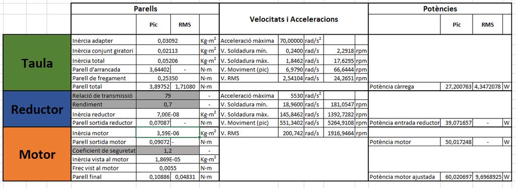
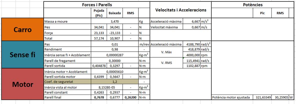
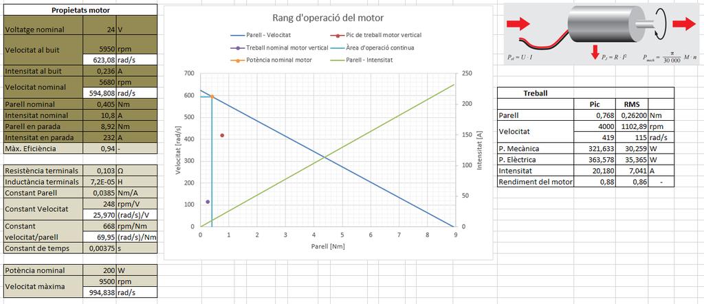
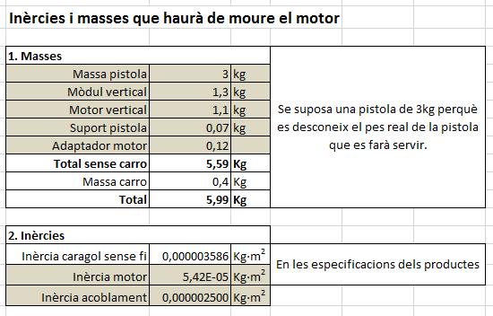
3 Càlculs sistema motor-reductor-taula
4
5
6
7
8
9
10

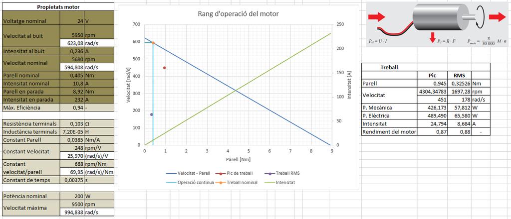
11 Càlculs sistema eix vertical
12
13
14
15
16

17 Càlculs eix horitzontal
18
19

20

21
22
23 ANNEX B: Fitxes tècniques
24 Planetary Gearhead GP 32 A 32 mm, Nm maxon gear M 1:2 Technical Data Planetary Gearhead straight teeth Output shaft stainless steel Shaft diameter as option 8 mm Bearing at output ball bearing Radial play, 5 mm from fl ange max mm Axial play max. 0.4 mm Max. axial load (dynamic) 120 N Max. force for press fi ts 120 N Direction of rotation, drive to output = Max. continuous input speed 6000 rpm Recommended temperature range C Number of stages Max. radial load, 10 mm from fl ange 90 N 140 N 200 N 220 N 220 N Option: Low-noise version Stock program Standard program Special program (on request) Gearhead Data 1 Reduction 2 Absolute reduction 3 Max. motor shaft diameter mm Part Numbers 1 Reduction 2 Absolute reduction 3 Max. motor shaft diameter mm Part Numbers 1 Reduction 2 Absolute reduction 3 Max. motor shaft diameter mm Part Numbers 1 Reduction 2 Absolute reduction 3 Max. motor shaft diameter mm Part Numbers 1 Reduction 2 Absolute reduction 3 Max. motor shaft diameter mm 4 Number of stages 5 Max. continuous torque Nm 6 Max. intermittent torque at gear output Nm 7 Max. effi ciency % 8 Weight g 9 Average backlash no load 10 Mass inertia gcm 2 11 Gearhead length L1 mm Part Numbers : 1 14 : 1 33 : 1 51 : : : : : : : : : : 1 18 : 1 66 : : : : : : : : : : 1 21 : 1 79 : : : : : : : : : : 1 86 : : : : : : : : : : : : : : : overall length overall length maxon Modular System + Motor Page + Sensor/Brake Page Overall length [mm] = Motor length + gearhead length + (sensor/brake) + assembly parts RE / RE /137 MR RE /137 Enc RE /137 HED_ / RE /137 DCT RE 25, 20 W RE 25, 20 W 136 MR RE 25, 20 W 136 HED_ / RE 25, 20 W 136 DCT RE 25, 20 W 136 AB RE 25, 20 W 136 HED_ 5540/AB / RE 25, 20 W 137 AB RE 25, 20 W 137 HED_ 5540/AB / A-max A-max MEnc A-max MR A-max Enc A-max HED_ / RE-max RE-max /186 MR maxon gear April 2015 edition / subject to change
25 Planetary Gearhead GP 32 A 32 mm, Nm M 1:2 Technical Data Planetary Gearhead straight teeth Output shaft stainless steel Shaft diameter as option 8 mm Bearing at output ball bearing Radial play, 5 mm from fl ange max mm Axial play max. 0.4 mm Max. axial load (dynamic) 120 N Max. force for press fi ts 120 N Direction of rotation, drive to output = Max. continuous input speed 6000 rpm Recommended temperature range C Number of stages Max. radial load, 10 mm from fl ange 90 N 140 N 200 N 220 N 220 N Option: Low-noise version maxon gear Stock program Standard program Special program (on request) Gearhead Data 1 Reduction 3.7 : 1 14 : 1 33 : 1 51 : : : : : : : : : 1 2 Absolute reduction Max. motor shaft diameter mm Part Numbers Reduction 4.8 : 1 18 : 1 66 : : : : : : : : : 1 2 Absolute reduction Max. motor shaft diameter mm Part Numbers Reduction 5.8 : 1 21 : 1 79 : : : : : : : : : 1 2 Absolute reduction Max. motor shaft diameter mm Part Numbers Reduction 23 : 1 86 : : : : : : : 1 2 Absolute reduction Max. motor shaft diameter mm Part Numbers Reduction 28 : : : : : : : : 1 2 Absolute reduction Max. motor shaft diameter mm Number of stages Max. continuous torque Nm Max. intermittent torque at gear output Nm Max. effi ciency % Weight g Average backlash no load Mass inertia gcm Gearhead length L1* mm *for EC 32 flat L1 is mm Part Numbers overall length overall length maxon Modular System + Motor Page + Sensor/Brake Page Overall length [mm] = Motor length + gearhead length + (sensor/brake) + assembly parts RE 30, 15 W RE 30, 15 W 138 MR RE 30, 15 W 138 HED_ / RE 30, 60 W RE 30, 60 W 139 MR RE 30, 60 W 139 HED_ / RE 35, 90 W RE 35, 90 W 140 MR RE 35, 90 W 140 HED_ / RE 35, 90 W 140 DCT RE 35, 90 W 140 AB RE 35, 90 W 140 HEDS 5540/AB / A-max / A-max / A-max /172 MR A-max /172 HED_ / EC 32, 80 W EC 32, 80 W 214 HED_ / EC 32, 80 W 214 Res EC 32 fl at, 15 W EC 32 fl at, IE, IP EC 32 fl at, IE, IP April 2015 edition / subject to change maxon gear 305
26 RE mm, Graphite Brushes, 60 Watt maxon DC motor M 1:2 Stock program Standard program Special program (on request) according to dimensional drawing shaft length 15.7 shortened to 8.7 mm Motor Data Values at nominal voltage 1 Nominal voltage V 2 No load speed rpm 3 No load current ma 4 Nominal speed rpm 5 Nominal torque (max. continuous torque) mnm 6 Nominal current (max. continuous current) A 7 Stall torque mnm 8 Stall current A 9 Max. efficiency % Characteristics 10 Terminal resistance Ω 11 Terminal inductance mh 12 Torque constant mnm/a 13 Speed constant rpm/v 14 Speed / torque gradient rpm/mnm 15 Mechanical time constant ms 16 Rotor inertia gcm 2 Part Numbers Specifications Operating Range Comments Thermal data 17 Thermal resistance housing-ambient 18 Thermal resistance winding-housing 19 Thermal time constant winding 20 Thermal time constant motor 21 Ambient temperature 22 Max. winding temperature 6.0 K/W 1.7 K/W 16.3 s 593 s C +125 C n [rpm] Continuous operation In observation of above listed thermal resistance (lines 17 and 18) the maximum permissible winding temperature will be reached during continuous operation at 25 C ambient. = Thermal limit. Mechanical data (ball bearings) 23 Max. speed rpm 24 Axial play mm 25 Radial play mm 26 Max. axial load (dynamic) 5.6 N 27 Max. force for press fits (static) 110 N (static, shaft supported) 1200 N 28 Max. radial load, 5 mm from flange 28 N Short term operation The motor may be briefl y overloaded (recurring). Assigned power rating Other specifications 29 Number of pole pairs 30 Number of commutator segments 31 Weight of motor Values listed in the table are nominal. Explanation of the figures on page 107. Option Preloaded ball bearings g maxon Modular System Overview on page Planetary Gearhead 32 mm Nm Page Koaxdrive 32 mm Nm Page 312 Spindle Drive 32 mm Page Recommended Electronics: Notes Page 22 ESCON 36/2 DC 378 ESCON Module 50/5 379 ESCON 50/5 380 EPOS2 Module 36/2 386 EPOS2 24/5, EPOS2 50/5 387 EPOS2 P 24/5 390 EPOS3 70/10 EtherCAT 393 MAXPOS 50/5 396 Encoder MR CPT, 3 channels Page 356 Encoder HED_ CPT, 3 channels Page 362/364 May 2015 edition / subject to change maxon DC motor 139
 Type Counts per turn Number of channels Max. operating frequency (khz) Max.")
27 Encoder MR Type L, CPT, 3 Channels, with Line Driver Cycle C = 360 e Pulse P = 180 e maxon sensor UHigh ULow UHigh ULow UHigh ULow s 3 Phase shift s 4 s 1 Channel A 90 e Channel B Channel I s 2 s 1..4 = 90 e s < 45 e Stock program Standard program Special program (on request) Type Counts per turn Number of channels Max. operating frequency (khz) Max. speed (rpm) Part Numbers Direction of rotation cw (definition cw p. 106) overall length overall length maxon Modular System + Motor Page + Gearhead Page + Brake Page Overall length [mm] / see Gearhead RE 30, 15 W RE 30, 15 W 138 GP 32, Nm 305 RE 30, 60 W RE 30, 60 W 139 GP 32, Nm 303 RE 30, 60 W 139 GP 32, Nm RE 30, 60 W 139 GP 32 S RE 35, 90 W RE 35, 90 W 140 GP 32, Nm 303 RE 35, 90 W 140 GP 32, Nm RE 35, 90 W 140 GP 32, Nm 310 RE 35, 90 W 140 GP 42, 3-15 Nm 314 RE 35, 90 W 140 GP 32 S RE 40, 25 W RE 40, 150 W RE 40, 150 W 142 GP 42, 3-15 Nm 314 RE 40, 150 W 142 GP 52, 4-30 Nm 318 A-max / A-max /172 GP 32, Nm A-max /172 GS 38, Nm 313 A-max /172 GP 32 S EC-max 40, 70 W EC-max 40, 70 W 228 GP 42, 3-15 Nm 315 EC-max 40, 120 W EC-max 40, 120 W 229 GP 52, 4-30 Nm 319 Technical Data Pin Allocation Connection example Supply voltage V CC 5 V ± 5% 1 N.C. Output signal TTL compatible 2 1 V 2 CC VCC Phase shift Φ 90 e ± 45 e 3 GND GND 4 N.C. Index pulse width 90 e ± 45 e 5 Channel A Operating temperature range C 6 Channel A Channel A Moment of inertia of code wheel 1.7 gcm 2 7 Channel B Output current per channel max. 5 ma Channel B Channel A 506 ±10 9 Channel I (Index) 10 Channel I (Index) Channel B DIN Connector 41651/ EN Channel B fl at band cable AWG 28 Encoder, Line Driver Channel I Channel I R R R Line receiver Recommended IC's: - MC SN AM 26 LS 32 The index signal Ι is synchronized with channel A or B. Opt. terminal resistance R > 1 kω 356 maxon sensor April 2015 edition / subject to change
28 RE mm, Graphite Brushes, 200 Watt maxon DC motor M 1:2 Stock program Standard program Special program (on request) Part Numbers Industrial Version IP54* Motor Data Values at nominal voltage 1 Nominal voltage V 2 No load speed rpm 3 No load current ma 4 Nominal speed rpm 5 Nominal torque (max. continuous torque) mnm 6 Nominal current (max. continuous current) A 7 Stall torque mnm 8 Stall current A 9 Max. efficiency % Characteristics 10 Terminal resistance Ω 11 Terminal inductance mh 12 Torque constant mnm/a 13 Speed constant rpm/v 14 Speed / torque gradient rpm/mnm 15 Mechanical time constant ms 16 Rotor inertia gcm Specifications Operating Range Comments Thermal data 17 Thermal resistance housing-ambient 18 Thermal resistance winding-housing 19 Thermal time constant winding 20 Thermal time constant motor 21 Ambient temperature 22 Max. winding temperature 3.8 K/W 1.2 K/W 71.7 s 1370 s C +125 C Mechanical data (preloaded ball bearings) 23 Max. speed 9500 rpm 24 Axial play at axial load < 11.5 N 0 mm > 11.5 N 0.1 mm 25 Radial play preloaded 26 Max. axial load (dynamic) 27 Max. force for press fits (static) (static, shaft supported) 28 Max. radial load, 15 mm from flange 30 N 150 N 6000 N 110 N Other specifications 29 Number of pole pairs 30 Number of commutator segments 31 Weight of motor Values listed in the table are nominal. Explanation of the figures on page 107. * Industrial version with radial shaft seal ring (resulting in increased no load current). IP54 protection only if mounted on brush side, in compliance with maxon modular system g n [rpm] Continuous operation In observation of above listed thermal resistance (lines 17 and 18) the maximum permissible winding temperature will be reached during continuous operation at 25 C ambient. = Thermal limit. Short term operation The motor may be briefl y overloaded (recurring). Assigned power rating maxon Modular System Overview on page Planetary Gearhead 52 mm 4-30 Nm Page 318 Planetary Gearhead 62 mm 8-50 Nm Page 320 Recommended Electronics: Notes Page 22 ESCON Mod. 50/5 379 ESCON 50/5 380 ESCON 70/ EPOS2 50/5 387 EPOS2 70/ EPOS3 70/10 EtherCAT 393 MAXPOS 50/5 396 Encoder HEDS CPT, 3 channels Page 363 Encoder HEDL CPT, 3 channels Page 365 Industrial Version IP54* Encoder HEDL 9140 Page 369 Brake AB 44 Page 412 End cap Page 413 May 2015 edition / subject to change maxon DC motor 143
29 Encoder HEDL CPT, 3 Channels, with Line Driver RS 422 Cycle C = 360 e Pulse P = 180 e maxon sensor UHigh ULow UHigh ULow UHigh ULow s 3 Phase shift s 4 s 1 Channel A 90 e Channel B Channel I s 2 s 1..4 = 90 e s < 45 e Stock program Standard program Special program (on request) Type Counts per turn Number of channels Max. operating frequency (khz) Max. speed (rpm) Shaft diameter (mm) Part Numbers Direction of rotation cw (definition cw p. 106) overall length overall length maxon Modular System + Motor Page + Gearhead Page + Brake Page Overall length [mm] / see Gearhead RE / RE /137 GP 26/GP /303 RE /137 KD 32, Nm 312 RE /137 GP 32, Nm 304/307 RE /137 GP 32 S RE 25, 20 W RE 25, 20 W 136 GP 26/GP /303 RE 25, 20 W 136 KD 32, Nm 312 RE 25, 20 W 136 GP 32, Nm 304/307 RE 25, 20 W 136 GP 32 S RE 25, 20 W 136 AB RE 25, 20 W 136 GP 26/GP /303 AB RE 25, 20 W 136 KD 32, Nm 312 AB RE 25, 20 W 136 GP 32, Nm 304/307 AB RE 25, 20 W 136 GP 32 S AB RE 25, 20 W 137 AB RE 25, 20 W 137 GP 26/GP /303 AB RE 25, 20 W 137 KD 32, Nm 312 AB RE 25, 20 W 137 GP 32, Nm 304/307 AB RE 25, 20 W 137 GP 32 S AB RE 30, 15 W RE 30, 15 W 138 GP 32, Nm 305 RE 30, 60 W RE 30, 60 W 139 GP 32, Nm RE 30, 60 W 139 KD 32, Nm 312 RE 30, 60 W 139 GP 32 S RE 35, 90 W RE 35, 90 W 140 GP 32, Nm RE 35, 90 W 140 GP 42, Nm 314 RE 35, 90 W 140 GP 32 S RE 35, 90 W 140 AB RE 35, 90 W 140 GP 32, Nm AB RE 35, 90 W 140 GP 42, Nm 314 AB RE 35, 90 W 140 GP 32 S AB Technical Data Pin Allocation Connection example Supply voltage V CC 5 V ± 10% 1 N.C. Output signal EIA Standard RS 422 V 2 CC VCC driver used: DS26LS GND GND 4 N.C. Phase shift Φ 90 e ± 45 e 5 Channel A Signal rise time 6 Channel A Channel A (typically, at C L = 25 pf, R L = 2.7 kω, 25 C) 180 ns 7 Channel B Signal fall time 8 Channel B Channel A 9 Channel I (Index) (typically, at C L = 25 pf, R L = 2.7 kω, 25 C) 40 ns 10 Channel I (Index) Index pulse width 90 e Channel B 10 9 Operating temperature range C Pin type DIN 41651/ Moment of inertia of code wheel 0.6 gcm 2 EN Channel B fl at band cable AWG 28 Max. angular acceleration rad s -2 Channel I Output current per channel min. -20 ma, max. 20 ma Option 1000 Counts per turn, 2 Channels Encoder, Line Driver, DS26LS31 Channel I R R R Line receiver Recommended IC's: - MC SN AM 26 LS 32 The index signal Ι is synchronized with channel A or B. Terminal resistance R = typical 120 Ω 364 maxon sensor April 2015 edition / subject to change
30 Encoder HEDL CPT, 3 Channels, with Line Driver RS 422 Cycle C = 360 e Pulse P = 180 e UHigh ULow UHigh ULow UHigh ULow s 3 Phase shift s 4 s 1 Channel A 90 e Channel B Channel I s 2 s 1..4 = 90 e s < 45 e maxon sensor Stock program Standard program Special program (on request) Type Counts per turn Number of channels Max. operating frequency (khz) Max. speed (rpm) Shaft diameter (mm) Part Numbers Direction of rotation cw (definition cw p. 106) overall length overall length maxon Modular System + Motor Page + Gearhead Page + Brake Page Overall length [mm] / see Gearhead RE 40, 25 W RE 40, 150 W RE 40, 150 W 142 GP 42, Nm 314 RE 40, 150 W 142 GP 52, Nm 318 RE 40, 150 W 142 AB RE 40, 150 W 142 GP 42, Nm 314 AB RE 40, 150 W 142 GP 52, Nm 318 AB RE 50, 200 W RE 50, 200 W 143 GP 52, 4-30 Nm 319 RE 50, 200 W 143 GP 62, 8-50 Nm 320 RE 65, 250 W RE 65, 250 W 144 GP 81, Nm 321 A-max A-max GP 26, Nm 301 A-max GS 30/GP /305 A-max GP 32, Nm 304/308 A-max GS 38, Nm 313 A-max GP 32 S A-max / A-max /172 GP 32, Nm A-max /172 GS 38, Nm 313 A-max /172 GP 32 S Technical Data Pin Allocation Connection example Supply voltage V CC 5 V ± 10% 1 N.C. Output signal EIA Standard RS 422 V 2 CC VCC driver used: DS26LS GND GND 4 N.C. Phase shift Φ 90 e ± 45 e 5 Channel A Signal rise time 6 Channel A Channel A (typically, at C L = 25 pf, R L = 2.7 kω, 25 C) 180 ns 7 Channel B Signal fall time 8 Channel B Channel A 9 Channel I (Index) (typically, at C L = 25 pf, R L = 2.7 kω, 25 C) 40 ns 10 Channel I (Index) Index pulse width 90 e Channel B 10 9 Operating temperature range C Pin type DIN 41651/ Moment of inertia of code wheel 0.6 gcm 2 EN Channel B fl at band cable AWG 28 Max. angular acceleration rad s -2 Channel I Output current per channel min. -20 ma, max. 20 ma Option 1000 Counts per turn, 2 Channels Encoder, Line Driver, DS26LS31 Channel I R R R Line receiver Recommended IC's: - MC SN AM 26 LS 32 The index signal Ι is synchronized with channel A or B. Terminal resistance R = typical 120 Ω April 2015 edition / subject to change maxon sensor 365
 Type Counts per turn Number of channels Max. operating frequency (khz) Max.")
31 Encoder HEDL CPT, 3 Channels, with Line Driver RS 422 Cycle C = 360 e Pulse P = 180 e maxon sensor UHigh ULow UHigh ULow UHigh ULow s 3 Phase shift s 4 s 1 Channel A 90 e Channel B Channel I s 2 s 1..4 = 90 e s < 45 e Stock program Standard program Special program (on request) Type Counts per turn Number of channels Max. operating frequency (khz) Max. speed (rpm) Shaft diameter (mm) Part Numbers Direction of rotation cw (definition cw p. 106) overall length overall length maxon Modular System + Motor Page + Gearhead Page + Brake Page Overall length [mm] / see Gearhead EC 32, 80 W EC 32, 80 W 214 GP 32, Nm EC 32, 80 W 214 GP 32 S EC 40, 170 W EC 40, 170 W 215 GP 42, Nm 314 EC 40, 170 W 215 GP 52, Nm 318 EC-max 30, 40 W EC-max 30, 40 W 226 GP 32, Nm 308/310 EC-max 30, 40 W 226 KD 32, Nm 312 EC-max 30, 40 W 226 GP 32 S EC-max 30, 40 W 226 AB EC-max 30, 40 W 226 GP 32, Nm 308/310 AB EC-max 30, 40 W 226 KD 32, Nm 312 AB EC-max 30, 40 W 226 GP 32 S AB EC-max 30, 60 W EC-max 30, 60 W 227 GP 32, Nm 308/310 EC-max 30, 60 W 227 KD 32, Nm 312 EC-max 30, 60 W 227 GP 42, 3-15 Nm 315 EC-max 30, 60 W 227 AB EC-max 30, 60 W 227 GP 32, Nm 308/310 AB EC-max 30, 60 W 227 KD 32, Nm 312 AB EC-max 30, 60 W 227 GP 42, 3-15 Nm 315 AB EC-max 40, 70 W EC-max 40, 70 W 228 GP 42, 3-15 Nm 315 EC-max 40, 70 W 228 AB EC-max 40, 70 W 228 GP 42, 3-15 Nm 315 AB EC-max 40, 120 W EC-max 40, 120 W 229 GP 52, 4-30 Nm 319 EC-max 40, 120 W 229 AB EC-max 40, 120 W 229 GP 52, 4-30 Nm 319 AB Technical Data Pin Allocation Connection example Supply voltage V CC 5 V ± 10% 1 N.C. Output signal EIA Standard RS 422 V 2 CC VCC driver used: DS26LS GND GND 4 N.C. Phase shift Φ 90 e ± 45 e 5 Channel A Signal rise time 6 Channel A Channel A (typically, at C L = 25 pf, R L = 2.7 kω, 25 C) 180 ns 7 Channel B Signal fall time 8 Channel B Channel A 9 Channel I (Index) (typically, at C L = 25 pf, R L = 2.7 kω, 25 C) 40 ns 10 Channel I (Index) Index pulse width 90 e Channel B 10 9 Operating temperature range C Pin type DIN 41651/ Moment of inertia of code wheel 0.6 gcm 2 EN Channel B fl at band cable AWG 28 Max. angular acceleration rad s -2 Channel I Output current per channel min. -20 ma, max. 20 ma Option 1000 Counts per turn, 2 Channels Encoder, Line Driver, DS26LS31 Channel I R R R Line receiver Recommended IC's: - MC SN AM 26 LS 32 The index signal Ι is synchronized with channel A or B. Terminal resistance R = typical 120 Ω 366 maxon sensor April 2015 edition / subject to change
32 Encoder HEDL CPT, 3 Channels, with Line Driver RS 422 Cycle C = 360 e Pulse P = 180 e UHigh ULow UHigh ULow UHigh ULow s 3 Phase shift s 4 s 1 Channel A 90 e Channel B Channel I s 2 s 1..4 = 90 e s < 45 e maxon sensor Stock program Standard program Special program (on request) Type Counts per turn Number of channels Max. operating frequency (khz) Max. speed (rpm) Shaft diameter (mm) Part Numbers Direction of rotation cw (definition cw p. 106) X drives overall length overall length maxon Modular System + Motor Page + Gearhead Page + Brake Page Overall length [mm] / see Gearhead EC-4pole 22, 90 W EC-4pole 22, 90 W 233 GP 22/GP /308 EC-4pole 22, 90 W 233 GP 32 S EC-4pole 22, 120 W EC-4pole 22, 120 W 234 GP 22/GP /308 EC-4pole 22, 120 W 234 GP 32 S EC-4pole 30, 100 W EC-4pole 30, 100 W 235 GP 32, Nm 310 EC-4pole 30, 100 W 235 GP 42, 3-15 Nm 315 EC-4pole 30, 100 W 235 AB EC-4pole 30, 100 W 235 GP 32, Nm 310 AB EC-4pole 30, 100 W 235 GP 42, 3-15 Nm 315 AB EC-4pole 30, 200 W EC-4pole 30, 200 W 237 GP 32, Nm 310 EC-4pole 30, 200 W 237 GP 42, 3-15 Nm 315 EC-4pole 30, 200 W 237 AB EC-4pole 30, 200 W 237 GP 32, Nm 310 AB EC-4pole 30, 200 W 237 GP 42, 3-15 Nm 315 AB EC-i 40, 50 W 243/ EC-i 40, 50 W 243 GP 32, 1-6 Nm 308 EC-i 40, 50 W 243/244 GP 42, 3-15 Nm 315 EC-i 40, 50 W 243 GP 32 S EC-i 40, 70 W 245/ EC-i 40, 70 W 245 GP 32, 1-6 Nm 308 EC-i 40, 70 W 245/246 GP 42, 3-15 Nm 315 EC-i 40, 70 W 245 GP 32 S EC-i 40, 100 W EC-i 40, 100 W 247 GP 42, 3-15 Nm 315 DCX 22 S online DCX 22 L online DCX 26 L online DCX 32 L 74 online DCX 35 L 75 online Technical Data Pin Allocation Connection example Supply voltage V CC 5 V ± 10% 1 N.C. Output signal EIA Standard RS 422 V 2 CC VCC driver used: DS26LS GND GND 4 N.C. Phase shift Φ 90 e ± 45 e 5 Channel A Signal rise time 6 Channel A Channel A (typically, at C L = 25 pf, R L = 2.7 kω, 25 C) 180 ns 7 Channel B Signal fall time 8 Channel B Channel A 9 Channel I (Index) (typically, at C L = 25 pf, R L = 2.7 kω, 25 C) 40 ns 10 Channel I (Index) Index pulse width 90 e Channel B 10 9 Operating temperature range C Pin type DIN 41651/ Moment of inertia of code wheel 0.6 gcm 2 EN Channel B flat band cable AWG 28 Max. angular acceleration rad s -2 Channel I Output current per channel min. -20 ma, max. 20 ma Option 1000 Counts per turn, 2 Channels Encoder, Line Driver, DS26LS31 Channel I R R R Line receiver Recommended IC's: - MC SN AM 26 LS 32 The index signal I is synchronized with channel A or B. Terminal resistance R = typical 120 Ω May 2015 edition / subject to change maxon sensor 367
 Combination of several drives via CAN Bus CANopen 6 digital inputs 2 digital outputs 2 analog inputs Miniaturized design Details pages 384 386 Slave version (online")
 or PC via USB or RS232 interface Typical applications: Small apparatus/appliances System automation tasks Drive technology Part Numbers EPOS2 24/2 380264, 390003 390438 maxon motor control Online")
 Details pages 384 386 Slave version (online commanding) using CAN Master (EPOS2 P, PC, PLC, SoftPLC, µ-processor, etc.")
 Interpolated Position Mode (PVT) Combination of several drives via CAN Bus CANopen 6 digital inputs 4")
33 EPOS2 Positioning Controllers Summary Online commanded EPOS2 24/2 Several device variations allows the operation of various maxon DC and EC micromotors up to 48 watts Point to point control (1 axis) Interpolated Position Mode (PVT) Combination of several drives via CAN Bus CANopen 6 digital inputs 2 digital outputs 2 analog inputs Miniaturized design Details pages Slave version (online commanded) using CAN Master (EPOS2 P, PC, PLC, SoftPLC, etc.) or PC via USB or RS232 interface Typical applications: Small apparatus/appliances System automation tasks Drive technology Part Numbers EPOS2 24/ , maxon motor control Online commanded EPOS2 Module 36/2 DC and EC motors up to 72 W Point to point control unit (1 axis) Interpolated Position Mode (PVT) Combination of several drives via CAN Bus CANopen 6 digital inputs 3 digital outputs 2 analog inputs Miniaturized open electronics board (OEM) Details pages Slave version (online commanding) using CAN Master (EPOS2 P, PC, PLC, SoftPLC, µ-processor, etc.) or PC via USB *) or RS232 *) interface requires external transceiver Typical applications: Small apparatus/appliances System automation tasks OEM customers Part Number EPOS2 Module 36/ Online commanded EPOS2 24/5 DC and EC motors up to 120 W Point to point control unit (1 axis) Interpolated Position Mode (PVT) Combination of several drives via CAN Bus CANopen 6 digital inputs 4 digital outputs 2 analog inputs Compact design Details pages Slave version (online commanding) using CAN Master (EPOS2 P, PC, PLC, SoftPLC, etc.) or PC via USB or RS232 interface Typical applications: Tool building Production equipment System automation tasks Part Number EPOS2 24/ Online commanded EPOS2 50/5 DC and EC motors up to 250 W Point to point control unit (1 axis) Interpolated Position Mode (PVT) Combination of several drives via CAN Bus CANopen 11 digital inputs 5 digital outputs 2 analog inputs 1 analog output Compact design Slave version (online commanding) using CAN Master (EPOS2 P, PC, PLC, SoftPLC, etc.) or PC via USB or RS232 interface Typical applications: Tool building Production equipment System automation tasks Part Number EPOS2 50/ Details pages Online commanded EPOS2 70/10 DC and EC motors up to 700 W Point to point control unit (1 axis) Interpolated Position Mode (PVT) Combination of several drives via CAN Bus CANopen 10 digital inputs 5 digital outputs 2 analog inputs Robust design Details pages Slave version (online commanding) using CAN Master (EPOS2 P, PC, PLC, SoftPLC, etc.) or PC via USB or RS232 interface Typical applications: Production equipment System automation tasks Plant construction Part Number EPOS2 70/ April 2015 edition / subject to change maxon motor control 383
. For that purpose product specific commands are available. EPOS2 is a modular constructed digital positioning controller.")

 or the actual axis position (relative).")
34 EPOS2 Positioning Controllers maxon motor control CANopen Slave (online commanded) Single motion and I/O commands from the process control are transmitted to the positioning control unit by a superior system (Master). For that purpose product specific commands are available. EPOS2 is a modular constructed digital positioning controller. It is suitable for DC and EC motors with incremental encoder with a power range from 1 to 700 watts. A number of operating modes provides flexible application in a wide range of drive systems in automation technology and mechatronics. Point to point The CANopen Profile Position Mode moves the position of the motor axis from point A to point B. Positioning is in relation to the axis Home position (absolute) or the actual axis position (relative). Interpolated Position Mode (PVT) Thanks to Interpolated Position Mode, the EPOS2 is able to synchronously run a path specified by interpolating points. With a suitable master, coordinated multi-axis movements as well as any profile in a 1-axis system can be carried out. (PVT = Position and Velocity versus Time) Position and Speed control with Feed Forward The combination of feedback and feed forward control provides ideal motion behavior. Feed forward control reduces control error. EPOS2 supports feed forward acceleration and speed control. Speed control In CANopen Profile Velocity Mode, the motor axis is moved with a set speed. The motor axis retains speed until a new speed is set. 384 maxon motor control April 2015 edition / subject to change
35 J1 J2 J3 J4 Torque control In Current Mode, a controlled torque can be produced on the motor shaft. The sinusoidal commutation used produces minimum torque ripple. Homing The CANopen Homing Mode is for referencing to a special mechanical position. There are more than 30 methods available for finding the reference position. Electronic gearhead In Master Encoder Mode, the motor follows a reference input produced by an external encoder. A gearing factor can also be defined using software parameters. Two motors can be very easily synchronized using this method. Step/Direction In Step/Direction Mode the motor axis follows a digital signal step-by-step. This mode can replace stepper motors. It can also be used to control the EPOS2 by a PLC without CAN interface. Standardized, extendable CANopen standard CiA 301, 402 and 305. Can easily be integrated into existing CANopen systems. Networks with other CANopen modules. Alternatively controllable by serial interface (USB and RS232). Flexible, modular The same technology for DC and EC motors. Configurable inputs and outputs for limit switches, reference switches, brakes and for other sensors and indicators near the drive. Easy start-up procedure Graphic user interface with many functions and wizards for start-up procedure, automatic control settings, I/O configuration, tests. Easy programming IEC libraries for CAN master units from industry leading manufacturers (Beckhoff, Siemens/Helmholz, VIPA) as well as 32/64-bit Windows DLLs for PC master units (IXXAT, Vector, National Instruments and Kvaser) are available. Programming examples for MS Visual C#, MS Visual C++, MS Visual Basic, Borland C++, Borland Delphi, National Instruments LabVIEW and National Instruments LabWindows/CVI are available at no charge. Also available: The 32/64-bit Linux Shared Object Library with programming examples for Eclipse C++/QT as well as ARMv6/v7 support for a wide variety of platforms (Raspberry Pi, BeagleBone). In addition, the maxon library for NI SoftMotion makes integration of EPOS2 in the National Instruments Compact Rio system easy. State-of-the-art Digital position, speed and current/torque control. Sinusoidal commutation for smooth operation of EC motors. maxon motor control Analog Commands In the position, speed and current mode it is possible to give commands via an external analog set value. This function offers further possibilities to operate the EPOS2 without serial on-line commanding. Power Supply J1A Logic Supply Motor Hall Sensor Encoder Signal 1 maxon motor control Positioning Contro ler EPOS2 50/ Made in Switzerland maxon motor Signal 2 J6 Signal 3 CAN Configuration CAN 2 J7 CAN 1 RS-232 J12 CAN 1 J8 J11 USB J10 LED Status J9 EPOS2 50/5 Capture inputs (Position Marker) Digital inputs can be configured so that the actual position value is saved when a positive and/ or negative edge of an input appears. + - J5 Trigger output (Position Compare) Digital outputs can be configured so that a digital signal is emitted at a set position value. Dual Loop Position and Speed Control With an additional sensor the load can be controlled directly and with high precision; the motor control is subordinated. The mechanical backlash and the elasticity can be compensated. Wide range of sensors can be handled: digital incremental encoder, SSI absolute encoder, analog incremental encoder (sin/cos). (Only in use with EPOS2 50/5 and EPOS2 70/10.) Control of Holding Brakes The control of the holding brake can be implemented in the device state management. There the delay times can be individually configured for switching on and off. Additional information for technical data of page 386/387 Operating modes CANopen Profile Position-, Profile Velocity- and Homing Mode Position, Velocity and Current Mode Alternative set value setting via Step/Direction, Master Encoder or external analog commanding Path generating with trapezoidal or sinusoidal profiles Feed forward for velocity and acceleration Interpolated Position Mode (PVT) Sinusoidal or block commutation for EC motors Dual loop position and speed controller Communication Communication via CANopen and / or USB 2.0/3.0 and / or RS232 Gateway function USB-to-CAN and RS232-to- CAN Inputs/Outputs Free configurable digital inputs e.g. for limit switches and reference switches Free configurable digital outputs e.g. for holding brakes Free analog inputs Available software EPOS Studio Windows DLL/Linux Shared Object Library IEC Libraries Firmware Available documentation Feature Chart Getting Started Cable Starting Set Hardware Reference Firmware Specification Communication Guide Application Notes Cable A comprehensive range of cables is available as an option. Details can be found on page 398. April 2015 edition / subject to change maxon motor control 385

36 EPOS2 24/5 Matched with DC brush motors with encoder or brushless EC motors with Hall sensors and encoder, from 5 to 120 watts. EPOS2 50/5 Matched with DC brush motors with encoder or brushless EC motors with Hall sensors and encoder, from 5 to 250 watts. EPOS2 70/10 Matched with DC brush motors with encoder or brushless EC motors with Hall sensors or encoder, from 80 to 700 watts. maxon motor control Controller versions CANopen Slave Electrical Data VDC VDC 0.9 x V CC 10 A 5 A 50 khz 10 khz 1 khz 1 khz rpm (sinusoidal); rpm (block) 15 µh / 5 A Input H1, H2, H3 A, A\, B, B\, I, I\ (max. 5 MHz) 6 (TTL and PLC level) 2 12-bit resolution, 0 +5 V configurable with DIP switch 1 7 Output 4 +5 VDC, max 100 ma +5 VDC, max. 30 ma V CC, max ma Interface RxD; TxD (max bit/s) high; low (max. 1 Mbit/s) Data+; Data- (max. 12 Mbit/s) Indicator green LED, red LED Ambient temperature and humidity range C C 20 80% Mechanical data Approx. 170 g 105 x 83 x 24 mm Flange for M3-screws Part Numbers EPOS2 24/5 CANopen Slave VDC VDC 0.9 x V CC 10 A 5 A 50 khz 10 khz 1 khz 1 khz rpm (sinusoidal); rpm (block) 22 µh / 5 A H1, H2, H3 A, A\, B, B\, I, I\ (max. 5 MHz) 11 (7 optically isolated, 4 differential) 2 (differential) 12-bit resolution, ±10 V configurable with DIP switch (4 optically isolated, 1 differential) 1 (12-bit, 0 10 V) +5 VDC, max. 100 ma +5 VDC, max. 30 ma +5 VDC, max. 150 ma RxD; TxD (max bit/s) high; low (max. 1 Mbit/s) Data+; Data- (max. 12 Mbit/s) green LED, red LED C C 20 80% Approx. 240 g 120 x 93.5 x 27 mm Flange for M3-screws EPOS2 50/5 CANopen Slave VDC VDC 0.9 x V CC 25 A 10 A 50 khz 10 khz 1 khz 1 khz rpm (sinusoidal); rpm (block) 25 μh / 10 A H1, H2, H3 A, A\, B, B\, I, I\ (max. 5 MHz) 10 (7 optically isolated, 3 differential) 2 (differential) 12-bit resolution, 0 +5 V configurable with DIP switch (4 optically isolated, 1 differential) +5 VDC, max. 100 ma +5 VDC, max. 30 ma +5 VDC, max. 150 ma; +5 VDC (R i = 1 kω) RxD; TxD (max bit/s) high; low (max. 1 Mbit/s) Data+; Data- (max.12 Mbit/s) green LED, red LED C C 20 80% Approx. 330 g 150 x 93 x 27 mm Flange for M3-screws EPOS2 70/10 Accessories DSR 50/5 Shunt regulator Order accessories separately, see page 398 April 2015 edition / subject to change DSR 50/5 Shunt regulator Order accessories separately, see page DSR 70/30 Shunt regulator Order accessories separately, see page 398 maxon motor control 387

37
38
39
40
41
42
 [N/mm] approx.")
43 Miniature Metal Bellows Coupling I Series MKM standard series with radial clamping hub technical data: MKM TN max. moment torsional max. shaft spring rate mass tightening torque speed of inertia stiffness misalignment (mm) [N/mm] approx. of screws size [Nm] [min -1 ] [10-6 kgm 2 ] [10-3 Nm/arcmin] axial ± lateral axial lateral [g] [Nm] 0,4 0, ,3 50 0,35 0, ,9 0, ,4 90 0,3 0, , ,5 0, , ,4 0, ,6 0, ,8 0, ,7 0, temperature range: -40 C up to +300 C material: bellows: stainless steel hubs: high-tensile strength aluminum screws: ISO 4762 / 12.9 Dimensions [mm]: length dimensions according to DIN ISO 2768 ch MKM Øa b c f h L ±0,5 ØD1/2min ØD1/2max 0,4 16,5 9 4,6 M 2,5 3, ,35 0,9 16,5 9 4,6 M 2,5 3,3 31,5 3 6, ,5 (27,5) 13 7,5 (9,6) M 3 4, (14) 4 24,5 (27,5) 13 7,5 (9,6) M 3 4,4 43, (14) M (44,5) 16,5 13 (15,5) M (24) (44,5) 16,5 13 (15,5) M (24) on request, couplings from size 2-12 are avaiable with EASY-clamp (see page 7) stock bores D1/D2 (G7) MKM Ø3 Ø4 Ø5 Ø6 Ø6,35 Ø8 Ø9,53 Ø10 Ø12 Ø15 Ø16 Ø19 0,4/0,9 2/4 7 8/12 note: further bore sizes possible on request order example: MKM 0,9 - D1 = 4 H7 D2 = 5 G7 30 Miniature Couplings
 [N/mm] approx.")
44 Miniature Metal Bellows Coupling I Series MKP short design with radial clamping hub technical data: MKP TN max. moment torsional max. shaft spring rate mass tightening torque speed of inertia stiffness misalignment (mm) [N/mm] approx. of screws size [Nm] [min -1 ] [10-6 kgm 2 ] [10-3 Nm/arcmin] axial ± lateral axial lateral [g] [Nm] , ,3 0, , ,3 0, ,4 0, ,5 0, ,4 0, ,5 0, temperature range: -40 C up to +300 C material: bellows: stainless steel hubs: high-tensile strength aluminum screws: ISO 4762 / 12.9 Dimensions [mm]: length dimensions according to DIN ISO 2768 ch MKP Øa b c f h L ±0,5 ØD1/2min ØD1/2max 2 24,5 (27,5) 13 7,5 (9,6) M 3 4, (14) 5 24,5 (27,5) 13 7,5 (9,6) M 3 4, (14) M (44,5) 16,5 13 (15,5) M (24) (44,5) 16,5 13 (15,5) M (24) M on request, all couplings are avaiable with EASY-clamp (see page 7) stock bores D1/D2 (G7) MKP Ø4 Ø5 Ø6 Ø6,35 Ø8 Ø9,53 Ø10 Ø12 Ø15 Ø16 Ø19 Ø24 2/5 7 8/12 25 note: further bore sizes possible on request order example: MKP 5 - D1 = 4 G7 D2 = 12 G7 Miniature Couplings 31
45
46
47
48 ANNEX C: Plànols
49 F F E 28 E 16,50 D A 2 SECTION A-A D 5 R1 7 C 50 3 A R2 8 8,60 8,60 C R B B M4 20 M4 31,11 42,43 A Autor: Data: Martí Salcedo 20/12/ MATERIAL: MASSA: TÍTOL: Acoblament_modul Alumini ESCALA: 0,06 Kg 1: A4 A
50 F F E E 55 D 7,50 42,43 D M C C R6 B 3,60 3 B 5 A Autor: Data: Martí Salcedo 20/12/ MATERIAL: MASSA: TÍTOL: Alumini Acoblament_motor ESCALA: 0,03 Kg 1: A4 A
51 F F E A A E D D 19 C C B B SECTION A-A SCALE 1 : 1 A Autor: Data: Martí Salcedo 20/12/ MATERIAL: MASSA: TÍTOL: Disc suport F112 ESCALA: 1,2 Kg 1: A4 A
52 F A F E M5 E SECTION A-A 5 A 4 D 8 D 190 M5 C C ,50 55 B 60 B A Autor: Data: Martí Salcedo 20/12/ MATERIAL: MASSA: TÍTOL: Peus Acer ESCALA: 1 Kg 1: A4 A
53 F 4 R4 48,70 F E 96,27 78,27 144,75 E 42 R8 88,81 D 102,83 D R C C B 5 6,50 B ,17 A Autor: Data: Martí Salcedo 20/12/ MATERIAL: TÍTOL: MASSA: X.DEC. S/EN DD12 Suport motor ESCALA: 2,03 Kg 1: A4 A
54 F 10 F R10 5 R15 F C 4 E M E 25,53 VIEW C D 28 D 40 8 C C 6,82 M B VIEW F B A Autor: Data: Martí Salcedo 20/12/ MATERIAL: MASSA: TÍTOL: Suport_pistola Alumini ESCALA: 0,07 Kg 1: A4 A
55 F 20 B B F , E 75 E D 80 12,16 58,20 D 37, ,85 R C 540 C 8 5 4,50 B SECTION B-B B A Autor: Data: Martí Salcedo 20/12/ MATERIAL: X.DEC. (SOLLASER SM-260) MASSA: TÍTOL: Taula-bancada ESCALA: 18,062 Kg 1: A4 A
EPOS2 24/2 EPOS2 24/5 DC (390438) EC (380264) DC/EC (390003) DCX (530239) (367676) (360665) (347717) (375711)
 EC (380264) DC/EC (390003) DCX (530239) (367676) (360665) (347717) (375711)") maxon motor control s EPOS2 are small-sized, full digital, smart positioning control units. Due to their flexible and high efficient power stage, the EPOS2 motion controllers drive brushed DC motors with
maxon motor control s EPOS2 are small-sized, full digital, smart positioning control units. Due to their flexible and high efficient power stage, the EPOS2 motion controllers drive brushed DC motors with
maxon document number:
 maxon document number: 791272-04 1 Table of contents... 2 2 Table of figures... 3 3 Introduction... 4 4 How to use this guide... 4 5 Safety Instructions... 5 6 Performance Data... 6 6.1 Motor data... 6
4 / 24,5 2,6 / steel, black coated. clockwise, viewed from the front face. ø15,9 ø17-0,052 ø6-0,05 8,1 ±0,3 2, T
 DC-Micromotors Precious Metal Commutation 4, mnm For combination with (overview on page 4-5) Gearheads: 5, 6, 6/7 Encoders: IE 6... 5 Series 4 74... SR Nominal voltage Terminal resistance Output power
TETRA COMPACT LOW VOLTAGE BRUSHLESS SERVOMOTORS
 TETRA COMPACT LOW VOLTAGE BRUSHLESS SERVOMOTORS BRUSHLESS TECHNOLOGY FEATURES AND BENEFITS Synchronous brushless servomotor, permanently excited Rated output power from 60W to 800W Maximum servomotor speed
BLuAC5 Brushless Universal Servo Amplifier
 BLuAC5 Brushless Universal Servo Amplifier Description The BLu Series servo drives provide compact, reliable solutions for a wide range of motion applications in a variety of industries. BLu Series drives
Brushless DC-Servomotors with integrated Encoder 4 Pole Technology
 rushless DC-Servomotors with integrated Encoder ole Technology mm For combination with Gearheads: F, /, 6 3... X + Encoders 3 ominal voltage Terminal resistance, phase-phase Output power ) Efficiency 3
The ZSH stepper motor convinces with its robust housing with high-strength cable gland. The motor is waterproof up to 10 m with the IP68 option.
 /ZSH HRSH ZSH Stepper otor Robust. Powerful. Reliable. Phytron s HRSHEnvironment motors are particularly suitable for challenging applications in mechanical engineering and industry. Challenging conditions
TETRA COMPACT - E AND FLEXI - PRO
 TETRA COMPACT - E AND FLEXI - PRO THE ENHANCED SERVO BUNDLE Motor Power Company introduces its new brushless servo bundle: TETRA COMPACT- ENHANCED, brushless servomotors, perfectly matched with the FLEXI-PRO
Brushless DC-Servomotors with integrated Encoder 4 Pole Technology
 rushless DC-Servomotors with integrated Encoder ole Technology 9 mm For combination with Gearheads: /(S),, L, /(S), /(S), /(S)... X + Encoders ominal voltage Terminal resistance, phase-phase Output power
LSM&DSD Brushless Servo Drive Package
 LSM&DSD Brushless Servo Drive Package Descriptions LSM&DSD brushless servo drive package consists of one of LSM60 brushless servo motors and DSD806 brushless servo drive, offering high performance with
Online data sheet AFS60B-S4PA AFS/AFM60 SSI ABSOLUTE ENCODERS
 Online data sheet FS60-S4P032768 FS/FM60 SSI FS60-S4P032768 FS/FM60 SSI C D E F Ordering information Type Part no. FS60-S4P032768 1037483 Other models and accessories www.sick.com/fs_fm60_ssi Illustration
BLuAC5 Brushless Universal Servo Amplifier
 BLuAC5 Brushless Universal Servo Amplifier Description The BLu Series servo drives provide compact, reliable solutions for a wide range of motion applications in a variety of industries. BLu Series drives
n Measuring range ,02 N m to N m n Clockwise and counter-clockwise torque n Low linearity deviation of ± 0.05 % F.S.
 Precision Torque Sensor Non-contact transmission for rotating applications Optional measurement of angle and speed Model 8661 Code: Delivery: Warranty: 2-3 weeks 24 months Application The 8661 precision
TETRA COMPACT - E AND FLEXI - PRO THE ENHANCED SERVO BUNDLE
 TETRA COMPACT - E AND FLEXI - PRO THE ENHANCED SERVO BUNDLE Mo t or P ow e r Com pa n y www.m ot orpow e rc o. c om info@m ot orpow e rc o. i t All r ight s re se rve d. Comple t e or pa rt i a l re produ
Lexium integrated drives
 Description ILp for CANopen, PROFIBUS DP, RS ILA with AC synchronous servo motor Description ILA comprise control electronics with a fieldbus interface for CANopen DS, PROFIBUS DP or RS and an AC synchronous
Express Delivery. Axial. Connection
 HIGH RESOLUTION INCREMENTAL SOLID SHAFT ENCODER FOR INDUSTRIAL APPLICATIONS Resolution up to 50.000 pulses per turn External diameter 58 mm Shaft from Ø 6 to 12 mm Protection class IP67 according to DIN
Online data sheet AFM60B-S4PC AFS/AFM60 SSI ABSOLUTE ENCODERS
 Online data sheet FM60-S4PC032768 FS/FM60 SSI C D E F H I J K L M N O P Q R S T Ordering information Type Part no. FM60-S4PC032768 1037504 Other models and accessories www.sick.com/fs_fm60_ssi Illustration
EC 45 flat with integrated electronics Document ID: en Operating Manual
 EC 45 flat with integrated electronics Document ID: 919801en Operating Manual Edition June 2017 The EC 45 flat with integrated electronics is a brushless, speed-controlled 1-quadrant drive. It is available
QR12. Output. A = Line Driver B = Line Driver ABZ/ Open Collector UVW C = Sin/Cos/ Line Driver UVW D = Sin/Cos/Open Collector UVW
 QR12 DESIGN FEATURES Low profile assembled height of 0.99" Bearing design simplifies encoder attachment Resolutions up to 20,000 lines per revolution SIN/COS outputs available up to 1250 LC 4, 6 or 8 pole
Incremental encoders Redundant sensing, isolated blind hollow shaft ø mm, cone shaft ø17 mm pulses per revolution
 Features Robust, compact housing Two bearings with large distance, one at each end High shaft load up to 450 N Shock resistant up to 250 g Shaft insulation up to 2.8 kv Highest operating speed 10000 rpm
maxon motor maxon motor control 1-Q-EC Amplifier DEC 24/1 Order numbers , , , ,
 maxon motor control 1-Q-EC Amplifier DEC 24/1 Order numbers 249630, 249631, 249632, 318305, 381510 September 2009 edition The DEC (Digital EC Controller) is a 1-quadrant amplifier for controlling electronically
Online data sheet AFS60E-S1AA AFS/AFM60 SSI ABSOLUTE ENCODERS
 Online data sheet FS0E-S0009 FS/FM0 SSI SOLUTE ENCODERS FS0E-S0009 FS/FM0 SSI SOLUTE ENCODERS C D E F Ordering information Type Part no. FS0E-S0009 0 Other models and accessories www.sick.com/fs_fm0_ssi
Optical encoder MEC22 HR
 Optical encoder MEC22 HR Description The MEC22 HR is a high resolution optical hollow shaft encoder that can be fixed quickly and easily on different sizes of motor shafts. The encoder provides two square
Measuring systems. 6/2 Built-on optoelectronic rotary encoders 6/2 Introduction
 Siemens AG 2008 Measuring systems /2 Built-on optoelectronic rotary encoders /2 Introduction /2 Incremental encoders /3 TTL (RS 422) /3 sin/cos 1 V pp /3 HTL /3 TTL (RS 422) double-track / Absolute encoders
Galil Motion Control. DMC 3x01x. Datasheet
 Galil Motion Control DMC 3x01x Datasheet 1-916-626-0101 Galil Motion Control 270 Technology Way, Rocklin, CA [Type here] [Type here] (US ONLY) 1-800-377-6329 [Type here] Product Description The DMC-3x01x
Torque Measuring Flange
 Force Torque Measuring Flange Digital Telemetry Based, Short-Design, Robust, High Accuracy Type 025DF... Type 025DF... torque measuring flanges operate on the strain gage principle. The integral, digital
Agilent AEDA-3300 Series Ultra Miniature, High Resolution Incremental Kit Encoders Data Sheet
 Description The AEDA-3300 series are high performance, cost effective, three-channel optical incremental encoder modules with integrated bearing stage. By using transmissive encoder technology to sense
BRUSHLESS DC MOTOR FAMILY
 BRUSHLESS DC MOTOR FAMILY Series NT HST Geared Brushless DC Permanent Magnet Motor The NT HST is designed to provide: Fast dynamic response High power density Compact package size Long life ball bearing
ABSOLUTE ROTARY ENCODER SSI
 Main Features - Compact and heavy-duty industrial model - Interface: Synchronous-serial (RS422/485) - Housing: 58 mm - Shaft: 6 or 10 mm - Resolution: Max. 25 Bit =,554,42 steps over 4,096 revolutions
Rotary Position Technology Incremental Encoders
 -40 to 80 C Temperature Shock/vibration resistant Short-circuit protected Reverse polarity protection High rotational speed Rugged Balanced, stainless-steel clamping rings, special bearing-shaft connection
3. HIWIN rotary tables TMS
 CRD Devices Ltd All Saints Industrial Estate, Shildon, Co, Durham, DL4 2RD Tel: +44 ()1388 7784 Fax: +44 ()1388 7788 E: sales@crd-devices.co.uk W: www.crd-devices.co.uk 3. HIWIN rotary tables TMS 3.1 Characteristics
Catalogue. Stepper Motors VRDM, ExRDM
 Catalogue Stepper Motors VRDM, ExRDM Stepper Motors Table of Contents -phase stepper motors Product description...................................... VRDM 6 Technical data........................................
Rotary Measurement Technology Incremental Encoders
 -20 to 60 C Temperature Shock/vibration resistant Short-circuit protection Reverse polarity protection High rotational speed Rugged Balanced, stainless-steel clamping rings, special bearing-shaft connection
ILA2E572PC1A0 integrated drive ILA with servo motor V - EtherCAT - indus connector
 Characteristics integrated drive ILA with servo motor - 24..48 V - EtherCAT - indus connector Main Range of product Product or component type Device short name Motor type Number of motor poles 6 Network
maxon motor maxon motor control 4-Q-EC Servoamplifier DES 70/10 Order number
 control 4-Q-EC Servoamplifier DES 70/10 Order number 228597 April 2006 Edition The DES (Digital EC Servoamplifier) is a very efficient digital servoamplifier with sinusoidal current commutation for perfectly
Incremental encoders Blind hollow shaft or cone shaft pulses per revolution
 Features TTL output driver for cable length up to 550 m Very high resistance to shock and vibrations Hybrid bearing for extended service life Shaft insulation up to.8 kv Large terminal box, turn by 80
Absolute encoders - SSI Solid shaft with clamping or synchro flange Optical multiturn encoders up to 14 bit ST / 16 bit MT
 Features Encoder multiturn / SSI Optical sensing method Resolution: max. singleturn 14 bit, multiturn 16 bit Clamping or synchro flange Electronic setting of zero point Counting direction input Available
Absolute encoders - SSI
 with through hollow shaft Features Encoder multiturn / SSI Optical sensing method Resolution: singleturn 14 bit, multiturn 12 bit Compact design Cost-efficient mounting High reliability by self-diagnostics
Absolute encoders - SSI Shaft with clamping or synchro flange Optical multiturn encoders 14 bit ST / 12 bit MT
 Features Encoder multiturn / SSI Optical sensing Resolution: singleturn 14 bit, multiturn 12 bit Clamping or synchro flange Electronic setting of zero point Counting direction input Suitable for high positive,
SEE IT BEFORE IT HAPPENS TETRA COMPACT LOW VOLTAGE BRUSHLESS SERVOMOTORS
 SEE IT BEFORE IT HAPPENS TETRA COMPACT LOW VOLTAGE BRUSHLESS SERVOMOTORS SEE IT BEFORE IT HAPPENS Mo t or P ow e r Com pa n y www.m ot orpow e rc o. c om info@m ot orpow e rc o. i t All r ight s re se
JR12 Jam Nut Mount Optical Encoder
 Improving the Quality of Life through the Power in Light JR12 Jam Nut Mount Optical Encoder QPhase Design Features: Replaces Size 15 Pancake Resolver Bearing design simplifies encoder attachment Resolutions
Absolute encoders - SSI Solid shaft with clamping or synchro flange Optical multiturn encoders up to 14 bit ST / 16 bit MT
 Features Encoder multiturn / SSI Optical sensing method Resolution: max. singleturn 14 bit, multiturn 16 bit Clamping or synchro flange Electronic setting of zero point Counting direction input Available
Absolute Encoders - Singleturn
 The Sendix 5853 and Sendix 5873 singleturn encoders with SSI or BiSS interface and optical sensor technology can achieve a resolution of max. 7 bits. These encoders are also available with an optional
Magnetic Encoder MEM 22
 Description The MEM 22 is a magnetic incremental encoder. He is a reliable low cost hollow shaft encoder that can be fixed quickly and easily on different sizes of motor shafts. The encoder MEM22 is designed
Data Sheet. AEDT-9340 Series High Temperature 115 C 1250/2500 CPR 6-Channel Commutation Encoder. Description. Features.
 AEDT-9340 Series High Temperature 115 C 1250/2500 CPR 6-Channel Commutation Encoder Data Sheet Description The AEDT-9340 optical encoder series are high temperature six channel optical incremental encoder
Online data sheet DFS60B-S4PA00S74 DFS60 INCREMENTAL ENCODERS
 Online data sheet DFS60B-S4PA00S74 DFS60 A B C D E F Illustration may differ Ordering information Type Part no. DFS60B-S4PA00S74 1081183 Other models and accessories www.sick.com/dfs60 H I J K L M N O
RoHS. High shaft load capacity. Shock / vibration resistant
 Due to their sturdy bearing construction in Safety Lock Design, the Sendix 5000 and 5020 offer high resistance against vibration and installation errors. The rugged housing, high protection level of up
Technical data. General specifications. Linearity error ± 0.1 Electrical specifications Operating voltage U B
 Model Number SYNCHRON SERIELLES INTERFACE Features Very small housing Up to 32 Bit multiturn SSI interface Free of wear magnetic sampling High resolution and accuracy Description The ENA36IL series are
Data Sheet MEM 16. Incremental Encoder Magnetic
 Incremental Encoder Magnetic PWB encoders GmbH Am Goldberg 2 D-99817 Eisenach Germany Phone: +49 3691 72580-0 Fax: +49 3691 72580-29 info@pwb-encoders.com MEM16IE Rev.2.1 / 15.12.2016 info@pwb-encoders.com
Magnetic absolute single-turn encoder BMSH MAGRES parallel
 Magnetic absolute single-turn encoder BMSH MAGRES parallel features robust single-turn encoder up to 9 bit parallel interface miniature housing zero-point programmable general data voltage supply 5 VDC
LENORD. +BAUER... automates motion. GEL 295x Customer-specific precision encoder. Technical Information Version General information.
 GEL 95x Customer-specific precision encoder LENORD +BAUER... automates motion. Technical Information Version 04- General information Extremly robust rotary encoder with stainless steel housing for measuring
The World of Motion Control
 PWB-Ruhlatec Industrieprodukte GmbH Siegburger Str.39a D-53757 Sankt Augustin Germany www.pwb-technologies.com info@pwb-technologies.com ME16 1 of 8 Rev.7.22 / 05.02.2007 Description The ME16 is a reliable
DRS61: Incremental encoders, number of lines and zero pulse width freely programmable DRS60: Incremental Encoders with Zero-Pulse-Teach
 NEW DRS: Incremental encoders, number of lines and zero pulse width freely programmable DRS: s with Zero-Pulse-Teach Further highlights of this generation of encoders: Simple zero-pulse-teach by pressing
 PWB encoders GmbH Am Goldberg 2 D-99817 Eisenach Germany Phone: +49 3691 72580-0 Fax: +49 3691 72580-29 info@pwb-encoders.com www.pwb-encoders.com 1 of 9 Description The ME22 is a reliable low cost optical
Technical data. General specifications V DC Power consumption P 0. 1 W Time delay before availability t v
 Model Number SYNCHRON SERIELLES INTERFACE Features Very small housing Up to 32 Bit multiturn SSI interface Free of wear magnetic sampling High resolution and accuracy Description The ENA36IL series are
IXARC Incremental Encoder UCD-IPT M100-PRD. Interface Programmable Incremental. Configuration Tool UBIFAST Configuration Tool (Version 1.6.
 IXARC Incremental Encoder UCD-IPT00-08192-M100-PRD Interface Interface Programmable Incremental Programming Functions PPR (1-16384), Output, Counting Direction Configuration Tool UBIFAST Configuration
Compact drives. Rotary actuators
 Compact drives Rotary actuators Production and delivery of servodrives and control systems. The Czech company TG Drives offers servodrives since 1995 for machines and equipments in industrial automation.
Magnetic absolute multi-turn hollow shaft encoder BMMH MAGRES SSI
 Magnetic absolute multi-turn hollow shaft encoder BMMH MAGRES SSI features robust multi-turn encoder up to - 2 bit single-turn resolution - 3 bit multi-turn resolution miniature housing zero point programmable
Data Sheet. HEDL-65xx, HEDM-65xx, HEDS-65xx Series Large Diameter (56 mm), Housed Two and Three Channel Optical Encoders. Description.
, Housed Two and Three Channel Optical Encoders. Description.") HEDL-65xx, HEDM-65xx, HEDS-65xx Series Large Diameter (56 mm), Housed Two and Three Channel Optical Encoders Data Sheet Description The HEDS-65xx/HEDL-65xx are high performance two and three channel optical
HEDL-65xx, HEDM-65xx, HEDS-65xx Series Large Diameter (56 mm), Housed Two and Three Channel Optical Encoders Data Sheet Description The HEDS-65xx/HEDL-65xx are high performance two and three channel optical
Features & Benefits 360, 512, 720, 1000, 1024, 1440, 1800, 2000, 2048, 2880, 3000, 3600, 4000, 4096, 5000, 5120, 6000, 7200, 8000, 8192, 9000, 10000
 CP-800/900 Series Size-25 Housed Rotary Optical Encoders Solid or hollow shaft, incremental, sine/cosine, or absolute format Allied Motion s CP800/900 series are size-25 (2.5 in. (63.5mm)) rotary optical
Multiturn absolute encoder
 0102 Model Number SYNCHRON SERIELLES INTERFACE Features Up to 30 Bit multiturn ATEX approval IECEx approval Flameproof enclosure Removable connection cap Galvanically isolated RS 22 interface Description
Measuring systems. 7/2 Overview. 7/3 Built-on optoelectronic rotary encoders 7/3 Introduction
 Siemens AG 2010 Measuring systems /2 Overview /3 Built-on optoelectronic rotary encoders /3 Introduction /4 Incremental encoders /4 sin/cos 1 V pp /4 RS 422 (TTL) /4 HTL /4 RS 422 (TTL) double-track /
DG 60 L Incremental Encoder
 Incremental Encoder Features Incremental encoder with 60 mm outer diameter ugged die-cast aluminum housing Quadrature output with reference marker, complementary output signals Protection to IP 67 Square
Encoder - Absolut 2RMHF-SSI
 Absolute Encoder: Ø24 mm Hollow Shaft: Ø3 mm to ¼ Inch Singleturn or Multiturn SSI Interface Binary or Gray Code Preset of Zero Position Choice of Counting Direction IP-Rating: IP64 or IP67 Mechanical
Servo Solutions for Continuous and Pulse Duty Applications
 Servo Solutions for Continuous and Pulse Duty Applications Servo drives, servo motors and geared servo motors Digitax ST Unidrive M700 Unimotor fm Unimotor hd Dynabloc fm Dynabloc hd Digitax ST is available
Online data sheet. ACM60B-S1KE13x06 ACM60 ABSOLUTE ENCODERS
 Online data sheet ACM60B-S1KE1x06 ACM60 A B C D E F H I J K L M N O P Q R S T Illustration may differ Detailed technical data Performance Number of steps per revolution Number of revolutions Ordering information
ABSOLUTE ROTARY ENCODER MULTI-TURN BIT PARALLEL
 Main Features - Compact and heavy-duty industrial model - Interface: Bit-parallel, push pull ΠShort circuit proof - Housing: 58 mm - Shaft: 6 or 10 mm - Resolution: Max. 25 Bit =,554,42 steps over 4,096
QR12 (1.22 ) Diameter Optical Encoder
 Diameter Optical Encoder") Improving the Quality of Life through the Power in Light QPhase QR12 (1.22 ) Diameter Optical Encoder Design Features: Low profile assembled height of Bearing design simplifies encoder attachment Resolutions
Improving the Quality of Life through the Power in Light QPhase QR12 (1.22 ) Diameter Optical Encoder Design Features: Low profile assembled height of Bearing design simplifies encoder attachment Resolutions
ABSOLUTE ROTARY ENCODER SSI
 Main Features - Compact and heavy-duty industrial model - Interface: Synchronous-serial (RS 422) - Housing: 58 mm - Shaft: 6 or 10 mm - Hollow shaft 12 mm - Blind hollow shaft 15 mm - Max. 65,56 steps
IRT Mini Evo. Technical Manual. quality IN MOTION. quality IN MOTION
 IRT quality IN MOTION www.irtsa.com 2000 Mini Evo Technical Manual IRT quality IN MOTION Contents 1. INTRODUCTION 3 2. DESCRIPTION 5 3. TECHNICAL DATA 7 3.1 GENERAL DATA FOR ALL TYPES 7 3.2 SPECIFIC DATA
The line driver option offers enhanced performance when the encoder is used in noisy environments, or when it is required to drive long distances.
 Large Diameter (56 mm), Housed Two and Three Channel Optical Encoders Technical Data HEDL-65xx HEDM-65xx HEDS-65xx Series Features: Two Channel Quadrature Output with Optional Index Pulse TTL Compatible
Online data sheet DFS60A-TEPZ00S09 DFS60 INCREMENTAL ENCODERS
 Online data sheet DFS60A-TEPZ00S09 DFS60 A B C D E F H I J K L M N O P Q R S T Illustration may differ Detailed technical data Features Special device Specialty Ordering information Other models and accessories
Motor Encoders. With Motor encoders Series M - Optimal control of motor feedback -
 Motor Encoders With Motor encoders Series M - Optimal control of motor feedback - Hengstler supplies the new high-performance motor encoder series M for use with brushless servo motors and stepper motors.
Technical data. General specifications. Linearity error ± 0.1 Functional safety related parameters MTTF d 700 a at 40 C Mission Time (T M ) L 10
 L 10") Model Number SYNCHRON SERIELLES INTERFACE Features Recessed hollow shaft SSI interface Up to Bit multiturn Free of wear magnetic sampling High resolution and accuracy Additionally push buttons for preset
Model Number SYNCHRON SERIELLES INTERFACE Features Recessed hollow shaft SSI interface Up to Bit multiturn Free of wear magnetic sampling High resolution and accuracy Additionally push buttons for preset
ABSOLUTE ROTARY ENCODER SSI
 Main Features - Compact and heavy-duty industrial model - Interface: Synchronous -serial (RS 422) - Housing: 58 mm - Shaft: 6 or 10 mm - Hollow shaft 12 mm - Blind hollow shaft 15 mm - Max. 65,56 steps
Mini Encoder High Resolution
 Mini Encoder High Resolution PWB encoders GmbH Am Goldberg 2 D-99817 Eisenach Germany Phone: +49 3691 72580-0 Fax: +49 3691 72580-29 info@pwb-encoders.com MEHR25 plug Rev.5A / 27.04.2017 info@pwb-encoders.com
8661 EN. Precision Torque Sensor Non-contact transmission for rotating applications optional measurement of angle and speed.
 Precision Torque Sensor Non-contact transmission for rotating applications optional measurement of angle and speed Model 8661 Code: Delivery: Warranty: 1-2 weeks 24 months CAD data 2D/3D for this sensor:
Soloist. Position Controller and Servo Amplifier PWM. Single axis digital servo controller with integral power supply and amplifier
 Soloist Position Controller and Servo Amplifier PWM Single axis digital servo controller with integral power supply and amplifier Advanced software architecture shortens customer development time; use
ADR-A Series Direct Drive Rotary Motor
 ADR-A Series Direct Drive Rotary Motor Direct drive, brushless motor fully integrated with encoder and bearing Low cogging torque Low speed and high speed windings Precise homing through index pulse ADR110
Absolute encoders - SSI Solid shaft with clamping or synchro flange Optical multiturn encoders 18 bit ST / 12 bit MT
 Features High resolution encoder multiturn / SSI Optical sensing method Resolution: singleturn 18 bit, multiturn 12 bit Electronic setting of zero point Counting direction input Available with additional
XXXX e. X d.. X X X a
 The Heavy Duty incremental encoder type 0H boasts a high degree of ruggedness in a very compact design. Its special construction makes it perfect for all applications in very harsh environments. / RoHS
/DSM 070 HIGH MOMENT OVERLOAD CAPACITY, HIGH CAPACITY OF THE INTEGRATED RADIAL-AXIAL OUTPUT BEARINGS, HIGH DYNAMIC PERFORMANCE.
 /DSM 070 The high precision DriveSpin DS 070 actuators represent the medium-size serially produced member of the DriveSpin product range, meeting even the most demanding requirements of customers from
Positioning drives DC motor, brushless Absolute multiturn position detection, Profibus-DP
 Features Positioning drive with worm gear bevel geared shaft Profibus-DP Brushless DC motor Absolute multiturn position detection Nominal power output 80 W inputs programmable Separate communication and
XXXX e. X d.. X X X a
 The Heavy uty incremental encoder type 0H boasts a high degree of ruggedness in a very compact design. Its special construction makes it perfect for all applications in very harsh environments. / RoHS
NOVOHALL Rotary Sensor non-contacting. Series RSC2800 digital SSI, SPI, Incremental
 NOVOHALL Rotary Sensor non-contacting Series RSC2800 digital SSI, SPI, Incremental The RSC 2800 sensor utilizes a contactless magnetic measurement technology to determine the measured angle. Unlike conventional
HD25. Industrial Rugged Metal Optical Encoder Page 1 of 6. Description. Mechanical Drawing. Features
 Description HD25 Page 1 of 6 The HD25 is a rugged optical incremental shaft encoder designed for heavy-duty industrial applications. The housing, machined from a solid billet aluminum block and finished
Incremental encoders 6
 Incremental encoders ELECTRONIC GmbH Incremental encoders 6 6.1 Explanatory notes...6-3 6.2 Functional description...6-4 6.3 Applications...6-5 6.4 Assembly examples...6-6 6.5 Alternative designs...6-8
Online data sheet AFS60A-BJPA AFS/AFM60 SSI ABSOLUTE ENCODERS
 Online data sheet FS0-JP FS/FM0 SSI FS0-JP FS/FM0 SSI C D E F H I J K L M N O P Q R S T Ordering information Type Part no. FS0-JP 09 Other models and accessories www.sick.com/fs_fm0_ssi Illustration may
ABSOLUTE ROTARY ENCODER SSI PROGRAMMABLE
 Main Features - Compact and heavy-duty industrial model - Interface: Synchronous-serial (RS422/485) - Housing: 58 mm - Shaft: 6 or 10 mm - Resolution: Max. 25 Bit =,554,42 steps over 4,096 revolutions
Data Sheet. AEDS-9240 Series 360/720 CPR Commutation Encoder Module. Features. Description. Applications
 AEDS-9240 Series 360/720 CPR Commutation Encoder Module Data Sheet Description The AEDS-9240 optical encoder is a six channel optical incremental encoder module. When used with a codewheel, this encoder
Data Sheet MEM 22. Incremental Encoder Magnetic
 Incremental Encoder Magnetic PWB encoders GmbH Am Goldberg 2 D-99817 Eisenach Germany Phone: +49 3691 72580-0 Fax: +49 3691 72580-29 info@pwb-encoders.com MEM 22 IE Rev.1.9 / 16.05.2017 info@pwb-encoders.com
Servo motors EMME-AS. Festo core product range Covers 80% of your automation tasks
 q/w Worldwide: Superb: Easy: Festo core product range Covers 80% of your automation tasks Always in stock Festo quality at an attractive price Reduces procurement and storing complexity qready for dispatch
Absolute Encoders Multiturn
 Absolute Encoders Multiturn Functional Safety, optical The absolute multiturn encoders Sendix 5863 SIL and 5883 SIL are perfectly suited for use in safety-related applications up to SIL3 according to DIN
Multiturn absolute encoder
 SYNCHRON SERIELLES INTERFACE Multiturn absolute encoder Release date: 2016-07-12 16:14 Date of issue: 2016-07-12 t4917_eng.xml Model Number Features Industrial standard housing Ø58 mm 0 Bit multiturn Data
Technical data. General specifications. Linearity error ± 0.1 Functional safety related parameters MTTF d 700 a at 40 C Mission Time (T M ) L 10
 L 10") Model Number SYNCHRON SERIELLES INTERFACE Features Solid shaft SSI interface Up to Bit multiturn Free of wear magnetic sampling High resolution and accuracy Additionally push buttons for preset function
Model Number SYNCHRON SERIELLES INTERFACE Features Solid shaft SSI interface Up to Bit multiturn Free of wear magnetic sampling High resolution and accuracy Additionally push buttons for preset function
Product Information ECN 424 S EQN 436 S. Absolute Rotary Encoders with DRIVE-CLiQ Interface for Safety-Related Applications
 Product Information ECN 424 S EQN 436 S Absolute Rotary Encoders with DRIVE-CLiQ Interface for Safety-Related Applications December 2016 ECN 424 S, EQN 436 S Rotary encoders for absolute position values
SEE IT BEFORE IT HAPPENS TETRA COMPACT LOW VOLTAGE BRUSHLESS SERVOMOTORS
 SEE IT BEFORE IT HAPPENS TETRA COMPACT LOW VOLTAGE BRUSHLESS SERVOMOTORS SEE IT BEFORE IT HAPPENS Mo t or P ow e r Com pa n y www.m ot orpow e rc o. c om info@m ot orpow e rc o. i t All r ight s re se
Stepper Motors WE CREATE MOTION
 WE CREATE MOTIO PRECIstep Technology EW Page FDM 6 Two Phase with Disc Magnet, AM 8 Two Phase,6 AM Two Phase,6 ADM S Two Phase with Disc Magnet, 6 7 AM Two Phase 6 8 AM Two Phase AM -R Two Phase WE CREATE
Absolute Encoders Singleturn
 The absolute singleturn encoders Sendix 5853 SIL and 5873 SIL are perfectly suited for use in safety-related applications up to SIL3 according to DIN EN ISO 6800-5- or PLe to DIN EN ISO 3849. The extra
Data Sheet. AEDB-9340 Series 1250/2500 CPR Commutation Encoder Modules with Codewheel. Features. Description. Applications
 AEDB-9340 Series 1250/2500 CPR Commutation Encoder Modules with Codewheel Data Sheet Description The AEDB-9340 optical encoder series are six-channel optical incremental encoder modules with codewheel.