ULTRASTAB 864U-2000 CURRENT TRANSDUCER USER S MANUAL
|
|
|
- Tyler Merritt
- 6 years ago
- Views:
Transcription

1 ULTRASTAB 864U-2000 CURRENT TRANSDUCER USER S MANUAL Distributed by: GMW Associates 955 Industrial Road, San Carlos, CA USA Tel: (650) Fax: (650) sales@gmw.com website: Manufactured by: Danfysik A/S Mollehaven 31 DK 4040 Jyllinge Denmark Tel: Fax: dfysik@inet.uni-c.dk
2 ULTRASTAB 864U Current Transducer system
3 2 TABLE OF CONTENTS PAGE 1. INTRODUCTION AND SPECIFICATIONS. 1.1 Introduction Working principle Warranty RECEIVING AND UNPACKING. 2.1 Receiving the goods Instructions for unpacking INSTALLATIONS. 3.1 Installation Interlock circuit How to adopt to the ULTRASTAB 864U output signal OPERATING INSTRUCTIONS. 4.1 Switching ON and Operating Instructions THEORY OF OPERATION. 5.1 General description of the Electronics The Eurocard circuit board assy Current transducer head MAINTENANCE APPENDIX C - SALES REPRESENTATIVE AND SERVICE...16 APPENDIX D - TEST AND CALIBRATION OF ULTRASTAB...17 D.1 Noise measurement...17 D.2 Absolute calibration and Offset adjustment...18 D.3 Offset adjustment...19
4 3 7. SPECIFICATIONS SPEC864U DRAWINGS. SCHEMATIC ASSEMBLY Dwg.No Dwg.No. 8.1 Wiring diagram A Schematic Output module Transducer head Dimensional drawing A 8.5 Interconnection cable to transducer head D 8. PARTS LISTS. Ultrastab 864U (1) Output module (4) Ultrastab 864I (5)
5 4 1.1 INTRODUCTION. The ULTRASTAB 864U assembly is a current transducer, designed for precision current measurement. The modular concept is prepared for installation in current controlled power supplies, gradient amplifiers or similar equipment. It consists of an Electronics part mounted on a single EURO-CARD and a programable CURRENT TRANSDUCER HEAD, which can be programmed in steps of 125A from 1000A to 2000 A Working principle. The ULTRASTAB 864U is a unique design based on the zero flux principle, for galvanically isolated current measurement. With the primary current fed through the transducer centre hole and current flowing, the electronics will generate a current in the built-in compensation winding, counter-balancing the primary ampere turns. TRANSDUCER HEAD ZERO FLUX DETECTOR I-prim. I-COMP. BURDEN RESISTER X 10 +/- 10V OUTPUT SENSE (HIGH) OUTPUT (HIGH) OUTPUT (LOW) GNDGND RTN (LOW) A very sensitive detector circuit will detect, when zero flux is obtained, and an analog 0 to V signal will be generated at the output terminals in a direct 0 to 100 % proportion to the primary current.
6 5 1.3 Warranty DANFYSIK A/S warrants the equipment delivered from the company to be free from any defects in materials and workmanship for a period of: 12 Months from the date of installation or max. 18 months from the date of shipment. Whichever is shortest. Within this warranty period DANFYSIK A/S will repair or replace any defective parts free of charge either on the customers site or at our factory at our choice. DANFYSIK A/S will pay or reimburse the lowest two way freight charges on any items returned to DANFYSIK A/S or our designated agent/representative provided prior written authorization for such return has been given by DANFYSIK A/S. This warranty shall not apply to any equipment which our inspection shows to our satisfaction, to have become defective or unworkable due to mishandling, improper maintenance, incorrect use, or any other circumstances, not generally acceptable for equipment of a similar type. DANFYSIK A/S reserves the right on standard products to make changes in design without incurring any obligation to modify previously manufactured units. The foregoing is the full extent of the warranty and no other warranty is expressed or implied. If no event Danfysik shall be liable for special damage arising from the delivery, late delivery, or use of the equipment. If any fault develops the following steps should be taken: Notify DANFYSIK A/S giving full details of the problems and include Model, Type, Serial number, and Order number. On receipt of this information DANFYSIK A/S will send you either service information or instructions for shipping. All shipments of DANFYSIK A/S equipment should be made according to our instructions and shipped in the original or a similar package. For smaller parts a cardboard carton will be sufficient, providing the parts are wrapped in plastic or paper and surrounded with at least 10 centimetres of shock-absorbing material.
7 6 2. RECEIVING AND UNPACKING RECEIVING THE GOODS The shipping package and the ULTRASTAB should be thoroughly inspected for signs of obvious physical damage immediately upon receipt. All materials in the package should be checked against the enclosed packing list and the list of standard delivery below. DANFYSIK A/S will not be responsible for any shortages unless notified immediately. ULTRASTAB 864U. Standard Delivery: - Electronics part on Eurocard. - Transducer head with connection cable and plug. - Manual INSTRUCTIONS FOR UNPACKING The ULTRASTAB is shipped in a cardboard carton. If the equipment is damaged in any way, a claim should be filed with the shipping agent, and a full report of the damage should be forwarded to Danfysik A/S or our local agent/representative immediately. Upon receipt of this report, you will be issued instructions for the repair, replacement or return shipment. Please include the Type No., Serial No., and Order No. for the ULTRASTAB on any communication with DANFYSIK or our representative.
8 7 3.1 INSTALLATION 1.Check that the specified DC voltages and currents are available, and the ambient temperature is within the recommended range. Please refer to wiring diagram and the specification sheets in this manual. 2.Install the electronics Eurocard in a crate in vertical position with a 64 pin socket connector, (Plug P1). 3.Plug P1, (64 pin). Establish connections for supply voltages and output signals to the plug. It is recommendable to fuse all supply connections. 4. Plug P2, (25 pin sub D). Connect the Transducer Head to the Eurocard via plug/socket P2. ( all terminals on plug P2 are also present on plug P1. I.e., if so preferred, the transducer head connection cable can be soldered to the socket of P1.) It is extremely important that this cable is mechanically secured with the two connector screws. Standard cable length is 2.5 metre. The transducer head may be installed in any orientation, but be careful to keep it away from power transformers, and other units producing magnetic stray fields. 5.The output signal is present on plug P1 at terminals 17 / 18 / 19 / 20. Please note, the four wire connections for optimum performance in the following section. Please also note, that it is recommendable to use a short cable for the output voltage. (Capacitive load less than 3 nf). 6. The system can now be used, i.e. the current to be measured can be switched on. Please see section INTERLOCK CIRCUIT The interlock circuit is present at plug P1 at the terminals No. AC30, 31, and 32. The terminals are floating contacts from a relay. The contacts can be used in the general safety interlock circuit of e.g. a power supply.
9 8 ULTRASTAB 864U. P1 Card connector. Please see diagram no for Card connections. AC 1 (NC). AC V, 1.3 A. AC 3 (NC). AC 4 BURDEN RESISTOR 0. AC 5 (BURDEN RESISTOR 0). AC 6-15V, 1.3 A. AC 7 (NC). AC 8 BURDEN RESISTOR + AC 9 (NC). AC 10 (NC). AC 11 (NC). AC 12 0 AC 13 (NC). AC 14 (NC). AC 15 (NC). A V C V AC 17 Output - signal sense AC 18 Output - signal AC 19 Output - RTN sense AC 20 Output - RTN AC 21 (Compensation winding). AC 22 (Feed back winding). AC 23 (Compensation winding). AC 24 (Feed back winding). A 25 (Jumper connection for type 2000 A head). C 25 (Jumper connection for type 2000 A head). AC 26 (Cable check - missing cable). A 27 (Detector winding). C 27 (Detector winding). AC 28 (Detector winding). AC 29 (Detector winding). AC 30 NC - Interlock relay. AC 31 NO - Interlock relay. AC 32 N - Interlock relay.
10 9 ULTRASTAB 864U. P2 (D - SUB25) Transducer head connections only. 1 Shield (Compensation winding). 2 Feed back winding. 3 Compensation winding. 4 (For optional fine control). 5 (For optional fine control). 6 (NC). 7 (NC). 8 R V 10 (NC). 11 Cable check - missing cable. 12 Detector winding. 13 Detector winding. 14 Feed back winding. 15 Compensation winding. 16 (NC). 17 (NC). 18 (NC). 19 (NC). 20 (NC). 21 (NC). 22 (NC). 23 Detector winding. 24 Detector winding. 25 Shield - Detector winding.
11 The four Terminal Output Signal Connections 1A R1 R2 SOCKET P1 AC17 SENSE (HIGH) Rb A1 A2 R5 C18 OUTPUT (HIGH 1A RTN C1 R3 R4 AC19 C20 SENSE (LOW) RTN (LOW) In order to obtain the highest performance from the ULTRASTAB 864U the output circuitry is designed as a 4 terminal system. The figure shows the output amplifier (simplified) used in the ULTRASTAB electronics module. The voltage across Rb at full input current is 1 V. The amplifiers A1 and A2 are connected as a differential amplifier system with a gain of 10 determined by the ratio R2/R1 = R4/R3 = 10. A2 is connected to have a gain of 10 so that the low noise amplifier A1 will have a gain of 1 and consequently will have its full bandwidth. Output Connections in General When a load is connected to the output terminals a current will flow resulting in a voltage drop in the cable and across the contact resistance in the connector. In order to, prevent this from altering the calibration a four terminal solution is used. The resistors R2 and R4 are connected to the "sense terminals" allowing the load current to have any value between zero and 5 ma without violating the calibration accuracy. The absolute calibration of the ULTRASTAB is made with the sense terminals HI: P1 pin AC17 and LO : P1 pin AC19 connected to the corresponding output terminals HI: pin C19 and LO: pin C20.
12 11 Output Connections with Cable and low Impedance Load In the case where a cable is needed between a low impedance load and the ULTRASTAB one twisted pair should be used for Hi and Lo, and another pair for the sense wires with the screen connected as shown. The resistance in the sense wires will act as an increment of R2 and R4 and consequently the calibration will be changed. TWISTED PAIR SENSE (HIGH) OUTPUT (HIGH) HIGH SENSE (LOW) RTN (LOW) LOW As an example a wire, 2.3 metres long with a cross section of 0.5 square mm will have a resistance of 87 mω. This will alter R2 by / = 8.7 ppm. R3 and R4 have the effect of reducing the influence of common mode currents running between the ULTRASTAB and the load. The common mode rejection is about equal to the relative accuracy of R2 = R4 and R1 = R3. The common mode rejection ratio is about 60 db or x Output Connection with Cable and high Impedance Load In the case, where a high impedance battery powered DVM or a differential amplifier is used, it is recommended to connect the sense wires to the outputs on the external P4 connector, and run a HI and a LO wire as twisted pair with common screen. TWISTED PAIR SENSE (HIGH) OUTPUT (HIGH) HIGH SENSE (LOW) RTN (LOW) LOW GUARD General Limits and Noise The output amplifier has a cut off frequency of about 60 MHZ., and it is sensitive to excessive capacitive loading (> 3 nf). This is another reason for using the shortest possible cable and it is mandatory that the LO terminal is connected to the LO input of the load unless it is a differential amplifier. The reason for this is that the capacitance (C1) in the mains transformer in the ULTRASTAB as well as the one in the load circuitry can form a common code loop through the ground and in this way introduce noise.
13 SWITCHING ON AND OPERATING INSTRUCTIONS When the instructions for installation in pos. 3.1 have been completed, the ULTRASTAB electronics can be switched ON. Please note: This unit must be switched on before the actual primary current source is applied, in order to avoid excessive saturation of the iron core in the transducer head. 1. Switch ON the DC power. The Green LED - NORMAL OPERATION on the PC board will be "ON" 2 The total assembly is in NORMAL OPERATION, and an analog voltage proportional to the measured current will be generated by the electronics circuitry at the output terminals. NORMAL OPERATION means: Cable connected, measured current within 115 % of selected maximum current. 3. The system can now be used. Highest performance is not reached until it has been ON for at least two hours. 4. If the Green LED,- NORMAL OPERATION is not "ON", recheck that all connections are properly made and secured by the screws. 5. If any problem should occur during this operation, please read Section 5 of this manual: General description of the Electronics, or contact our local representative or Danfysik direct. 6. All performance data refers to max. current for the type 2000A transducer head. In order to obtain maximum accuracy of the instrument, lower currents can be measured by applying more primary turns through the transducer head and divide the output signal with the number of turns. For high sensitivity measurements it is important to distribute the turns with even space all around on the transducer head. 7. The offset adjustment is carried out with the potentiometer R48. RECOMMENDATION To obtain maximum performance always switch ON control power before applying the current which shall be measured through the transducer head. Nothing will be damaged if this sequence is not followed but the saturation effect may cause a drift in the offset.
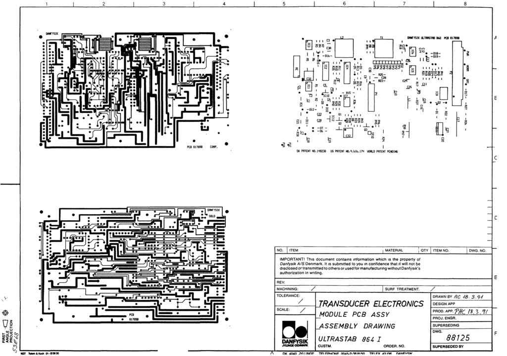
14 GENERAL DESCRIPTION OF THE ELECTRONICS The ULTRASTAB 864U electronics is mounted on an Eurocard. The circuit board is equipped with two connectors: The rear end has connector P1 for power supply, analog output current, ground connection and an optional connections to the transducer head. The front end has connector P2 for the transducer cable, providing connections between the electronics and the transducer head. Please refer to schematic No and circuit board assembly drawing No The circuit receives signals from the zero flux detector and drives the compensation current in such a way that the secondary ampere turns of the transducer head counter-balances the primary ampere turns. At the same time the voltage across the secondary winding is kept to a minimum - I. e. it approaches the ideal current transformer. 5.2 THE EUROCARD CIRCUIT BOARD ASSY The module contains circuits for: A. Low voltage power supply. B. Zero flux detector. C. Compensation current circuit. D. Output amplifier with burden resistor E. Interlock circuit. A. Low voltage power supply. The low voltage power supply is shown in the upper left corner of the schematic No. 884xx. The zero flux detector is powered through the voltage regulator IC 10. B. Zero flux detector. The zero flux detector is detecting, and via a feed back circuitry controlling that the flux in the transducer head is brought to zero. In this situation the compensating current in the transducer head is directly proportional to the primary current via the transfer ratio of the turns. A free running oscillator is driving the detector circuit. The oscillator operation can be checked at test point TP 6.
15 14 C. Compensation current circuit. The compensating current circuit is controlled from the zeroflux detector. The amplifiers involved are IC 5, IC 6 and IC 8. D. Output amplifier with burden resistor. Please refer to schematic This circuit bord converts the nominal 0 to 1A secondary current to a corresponding 0 to 10V. Output voltage. It is mounted on a heatsink and connected to the eurocard via a dual flexstrip. E. Interlock circuit. When the compensating winding cannot cancel the ampere turns of the primary current, the zero detector windings will saturate and the magnetizing currents will go to a high value. The voltage on TP 4 being the average of the two driver outputs will go low. This is detected by IC 7 A driving the LED "Normal" and the relay RL 1 off. The relay contacts are available for an external interlock system. At the same time IC 4 B switches the connection to the output amplifier from the ZERODETECTOR to the bistable circuit IC7 B. The compensation amplifier IC 8 now starts sweeping the compensating current. In case the primary current is below say half its maximum rated value, the compensating current will at some time cancel the primary ampere turns. The cores will now be desaturated and the circuit will "lock in". The interlock circuit receives an AC signal from the ZERODETECTOR driver via a jumper in the transducer head. This signal is rectified and it drives Q 3 which is part of the interlock chain. In this way both a missing driving signal and a missing cable connection are detected. 5.3 CURRENT TRANSDUCER HEADS Please see drawing The transducer head has an Aarrow sticker@ on the side face. With the main current flowing in the direction of the arrow, a negative voltage will be developed across an external Burden resistor. ( In the case, that the 864I Eurocard electronics is delivered with a +/- 10V output module, and then named 864U- the output voltage will be positive with the current flowing in the direction of the arrow.). The transducer heads can be mounted in any orientation, and the influence from external stray fields is low. The transducer head contains fragile materials in the zero detector assembly, and care should be taken in handling. The electronics is factory adjusted to the transducer head for zero offset, i.e. optimum performance. If readjustment of the zero offset is necessary, resistor R 48 shall be adjusted with zero primary current through the transducer head. Please refer to R 48 and schematic
16 MAINTENANCE The ULTRASTAB 864U assembly does not require any maintenance under normal operation. If faults should occur, please refer to schematic No and the Theory of Operation section in this manual. The schematic contains information about voltage levels, at the test points (TP..). Please note: Faults within the calibrated components and the zero flux detector can only be repaired by returning the ULTRASTAB 864u assembly to Danfysik A/S or our local representative. Failure to do this will make the warranty null and void.
17 16 APPENDIX C. - SALES REPRESENTATIVE AND SERVICE. DANFYSIK A/S, Moellehaven 31, DK-4040 Jyllinge DENMARK. Phone No.: Fax No.: No.:danfysik@danfysik.dk FACTORY REPRESENTATIVES GMW ASSOCIATES, 955 Industrial Road San Carlos CA P.O. Box 2578 Redwood City CA U. S. A. Phone No.:(650) Fax No.:(650) TRANSACT INDIA CORPORATION 5/1A, Grants Building Arthur Bunder Road Colaba Mumbai INDIA Phone No.:(22) Fax No.:(22) MARUBUN CORPORATION Marubun Daiya Bldg. 8-1, Nihonbashi Odenmacho Chuo-ku Tokyo 103 JAPAN Phone No.:( 3 ) Fax No.:( 3 )
18 17 APPENDIX D - TEST AND CALIBRATION OF ULTRASTAB D.1Noise Measurements on ULTRASTAB 864U All ULTRASTAB 864U electronic units are tested for noise figures before leaving the factory. This Appendix D.1 describes the method used in details, and can be used for rechecking the instruments in the field. TRANSDUCER HEAD ULTRASTAB 864U SENSE (HIGH) A=100 OUTPUT (HIGH) OUTPUT (LOW) 1K5 C HIGH LOW AC mv DVM Fo > 100KHz SENSE (LOW) The filtering technique can also be used to limit the bandwidth of the 864U in applications, where a more narrow bandwidth is acceptable and a lower noise figure is desirable. An amplifier with a gain of 100 and a bandwidth exceeding 1 MHZ is connected directly to the P4 terminals of the ULTRASTAB unit to be tested (please see fig. in section 4.4 case B). A coaxial cable connects the output of the amplifier with the input of a single pole low pass filter mounted on the terminals of the digital voltmeter (DVM). The capacitor C is selectable so that cut off frequencies form 10 Hz to 100 khz can be selected in decade steps. The voltmeter used is a FLUKE DVM measuring AC RMS. Set in the 200 mv range this gives 1 ppm/mv referred to the 10 V output from the ULTRASTAB unit. The table shows measurements for 2 selected heads and it is seen that the values are closely proportional to the square root of the frequency band used. This compares well with the situation of amplifiers. Average Figures measured on ULTRASTAB 864U Filter cut off Capacitor 1000A 2000A head Frequency.C 10 Hz. 10 uf ppm ppm. 100 Hz. 1 uf. 0.3 ppm. 0.9 ppm. 1 khz 100 nf. 0.6 ppm. 2.0 ppm. 10 khz. 10 nf. 3.3 ppm ppm. 50 khz. 2 nf. 7.4 ppm 7.3 ppm DOC.NO. APPENCA
19 18 D.2 ULTRASTAB 864U - Absolute calibration and Offset adjustment All ULTRASTAB 864U assemblies are absolute calibrated before leaving the factory. The class of DVM and precision shunt needed for the purpose is rather high and it is 1A CURRENT SOURCE ULTRASTAB 864U REF. RESISTER X10 BURDEN RESISTER INPUT A INPUT B 8 1/2 DIGIT DVM recommended to send the ULTRASTAB assembly direct back to DANFYSIK or to our local sales representative in the case, where re-calibration is needed. The figure shows the set up used for the absolute calibration of the ULTRASTAB 864U. The Reference Resistor is temperature stabilized in a oilbath. The 8 2 digit DVM DATRON type 1281 has two input ports which measures the voltage across the Reference resistor and the voltage output from the ULTRASTAB 864U The calibration of as well the standard resistor as the voltmeter at DANFYSIK are traceable to National and International Standard Laboratories. The calibration is basically a calibration of the current to voltage converter circuitry in which a +-1A (compensation) current is converted to a +-10V analog output voltage via a Burden resistor and a x10 amplifier. The current conversion in the transducer head has a fixed (not variable) transfer ratio, which can not change during actual service. The transfer ratio of the transducer heads is tested during production of the individual heads where the no of turns is controlled to be absolute precise, ie the winding tolerance is +-0. DOC.NO. APPENCA
20 19 Check of Calibration. Before actual check of calibration can start the 864U must warm up for at least 1 hour. Please note that the transducer head is not connected during the calibration check.. Offset of the output amplifier. The analog output voltage shall be below V, measured on the output socket at the rear side of the cabinet.if adjustment is necessary trimmer R8 on the output amplifier board shall be used. Gain measurement of the Output Amplifier. Via the socket P1 a +-1A is applied from an external source. The output voltage is measured on P1 socket. The voltage shall be +-10V within microv. D3. Offset adjustment. 1.Switch on the 864U for 1 hours heating up and stabilization. (During initial adjustment the electronic unit is switched on for one week burn in period before any adjustment is started). 2.The adjustment shall be carried out at normal operation temperature. 3.A high precision DVM (8 2 Digit Datron) is used during the zero offset calibration work. The DVM is connected to the analog output. 4.First offset adjustment step is carried out with no transducer head connected. Potentiometer R8 on the output amplifier board is adjusted until the DVM shows <5µV. 5.Next offset adjustment step is carried out with the transducer head connected. Potentiometer "OFFSET ADJ" on the eurocard is adjusted until DVM shows <5µV). DOC.NO. APPENCA
21
 CABLE")


 REV.")

 :;,.")


22 SOCKET FOR CONNECTION. r TRANSDUCER (P2) CABLE OFFSET ADJUSTMENT 2. Ln v r SOCKET FOR CRATE CONNECTIONS. CARD DIMENSIONS looxl60 (Pl) REV.. MA TERIALI MACHINING. SURF TREATMENTI T[JLERANCEI [ -t p SCALE:.1'1 (A4) :;,...~ ~i~ e ;::: u DANFYSIK JYLlK rotiark ELECTRONICS ASSEMBLY DRA'JN BY KP DESIGN APP. 'I/j -?-tpn( PRDD.APP. 'I(G: -<:2 '7 & PRDJ.ENGR. ON EURDCARD SUPERSEDING ULTRASTAB CUSTM. D'w'GI 864U ORDER NO lsuperseded BY
23
24
25
26
27 FIRST ANGLE PROJECTION IMPORTANT! This document contains information which is the proporty of Danfysik A/S, Denmark. It is submitted to you in confidence that it will not be disclosed or transmitted to others without Danfysik's authorization. INTERCONNECTION CABLE TRANSDUCER ELECTRONICS TRANSDUCER HEAD ULTRASTAB 864 DWG.NO.: PROJ.ENGR. PROD.APP. DESIGN APP. DRAWN BY - TS PHC KP D CUSTOMER:. ORDER NO.. REVISION: D SHEET 1 OF 1 FILE: DK-4040 JYLLINGE DENMARK. TELEPHONE: TELEFAX: DANFYSIK@DANFYSIK.DK. DATE: MK SIZE: A4
DANFYSIK A/S - DK-4040 JYLLINGE - DENMARK
 2 TABLE OF CONTENTS PAGE 1. INTRODUCTION AND SPECIFICATIONS. 1.1 Introduction... 4 1.1.1 Working principle....4 1.2 Warranty...5 2. RECEIVING AND UNPACKING. 2.1 Receiving the goods....6 2.2 Instructions
ULTRASTAB IHF Precision Current Transducer
 ULTRASTAB 867-200IHF Precision Current Transducer The Ultrastab 867-200IHF Current Transducer is a model in the Ultrastab Current Transducer program. It is the second generation of current transducers
ULTRASTAB I U Precision
 ULTRASTAB 867-700I 867-700U Precision Current Transducer The Ultrastab 867-700I and 867-700U Current Transducers, are the latest models of the Ultrastab Current Transducers. They are the third generation
Feed back element in high performance gradient amplifiers Feed back element in precision current regulated power supplies
 ULTRASTAB 866 Precision Current Transducer The Ultrastab 866 Current Transducer is the most proven fluxgate transducer with onboar electronics in the Danfysik Current Transducer program. It is the first
For ultra-high precision measurement of current: DC, AC, pulsed..., with galvanic separation between primary and secondary. Applications.
 Current Transducer IT 700-S ULTRASTAB I PM = 700 A For ultra-high precision measurement of current: DC, AC, pulsed..., with galvanic separation between primary and secondary. Features Closed loop (compensated)
For ultra-high precision measurement of current: DC, AC, pulsed..., with galvanic separation between primary and secondary. Applications.
 Current Transducer IT 605-S ULTRASTAB I PN = 600 A For ultra-high precision measurement of current: DC, AC, pulsed..., with galvanic separation between primary and secondary. Features Wide operating temperature
For ultra-high precision measurement of current: DC, AC, pulsed..., with galvanic separation between primary and secondary. Applications.
 Current Transducer IT 700-SB ULTRASTAB I PM = 700 A For ultra-high precision measurement of current: DC, AC, pulsed..., with galvanic separation between primary and secondary. Features ± 10 V voltage output
For ultra-high precision measurement of current: DC, AC, pulsed..., with galvanic separation between primary and secondary. Applications.
 Current Transducer IT 205-S ULTRASTAB I PN = 200 A For ultra-high precision measurement of current: DC, AC, pulsed..., with galvanic separation between primary and secondary. Features Wide operating temperature
AMP-13 OPERATOR S MANUAL
 AMP-13 OPERATOR S MANUAL Version 2.0 Copyright 2008 by Vatell Corporation Vatell Corporation P.O. Box 66 Christiansburg, VA 24068 Phone: (540) 961-3576 Fax: (540) 953-3010 WARNING: Read instructions carefully
For ultra-high precision measurement of current: DC, AC, pulsed..., with galvanic separation between primary and secondary. Applications.
 Current Transducer IT 200-S ULTRASTAB I PM = 200 A For ultra-high precision measurement of current: DC, AC, pulsed..., with galvanic separation between primary and secondary. Features Closed loop (compensated)
80i-600A AC Current Probe
 x Instruction Sheet 80i-600A AC Current Probe INTRODUCTION The Model 80i-600A is a clamp-on ac current probe designed to extend the current measuring capability of an ac current meter to 600 amperes. A
OPERATION & SERVICE MANUAL FOR FC 110 AC POWER SOURCE
 OPERATION & SERVICE MANUAL FOR FC 100 SERIES AC POWER SOURCE FC 110 AC POWER SOURCE VERSION 1.3, April 2001. copyright reserved. DWG No. FC00001 TABLE OF CONTENTS CHAPTER 1 INTRODUCTION... 1 1.1 GENERAL...
Model MV106J/MV116J. ±10nVdc to ±11Vdc Precision DC Voltage Standard Source. Operating Manual
 Model MV106J/MV116J ±10nVdc to ±11Vdc Precision DC Voltage Standard Source Operating Manual This page intentionally left blank. MV 106 & MV116 OPERATORS MANUAL Serial No. Win-man\mvman.wpd This page intentionally
Model 9305 Fast Preamplifier Operating and Service Manual
 Model 9305 Fast Preamplifier Operating and Service Manual This manual applies to instruments marked Rev 03" on rear panel. Printed in U.S.A. ORTEC Part No.605540 1202 Manual Revision B Advanced Measurement
For the electronic measurement of current: DC, AC, pulsed..., with galvanic separation between the primary and the secondary circuit.
 Current Transducer IN 1000-S N = 1000 A For the electronic measurement of current: DC, AC, pulsed..., with galvanic separation between the primary and the secondary circuit. Features Closed loop (compensated)
Model Hz to 10MHz Precision Phasemeter. Operating Manual
 Model 6610 1Hz to 10MHz Precision Phasemeter Operating Manual Service and Warranty Krohn-Hite Instruments are designed and manufactured in accordance with sound engineering practices and should give long
Model 7000 Low Noise Differential Preamplifier
 Model 7000 Low Noise Differential Preamplifier Operating Manual Service and Warranty Krohn-Hite Instruments are designed and manufactured in accordance with sound engineering practices and should give
Broadband Power Amplifier
 601L Broadband Power Amplifier HIGH RF VOLTAGES MAY BE PRESENT AT THE OUTPUT OF THIS UNIT. All operating personnel should use extreme caution in handling these voltages and be thoroughly familiar with
High Performance Current Transducer IT 200-S ULTRASTAB = A. ε L
 High Performance Current Transducer IT 200-S ULTRASTAB For the electronic measurement of currents: DC, AC, pulsed..., with galvanic isolation between the primary circuit and the secondary circuit. I PM
DIN Thermocouple Conditioner MODEL 5M14(V)
") 5M14 1.A.0.5M14 DIN Thermocouple Conditioner MODEL 5M14(V) QUAD ISOLATED THERMOCOUPLE CONDITIONER Module 1 GENERAL DESCRIPTION AND SPECIFICATIONS The Model 5M14(V) is a precision conditioner designed for
5M14 1.A.0.5M14 DIN Thermocouple Conditioner MODEL 5M14(V) QUAD ISOLATED THERMOCOUPLE CONDITIONER Module 1 GENERAL DESCRIPTION AND SPECIFICATIONS The Model 5M14(V) is a precision conditioner designed for
Model 34A. 3Hz to 2MHz 2-Channel Butterworth/Bessel HP, LP, BP, BR Plug-In Filter Card for Model 3905/3916 Chassis.
 Model 34A 3Hz to 2MHz 2-Channel Butterworth/Bessel HP, LP, BP, BR Plug-In Filter Card for Model 3905/3916 Chassis Operating Manual Service and Warranty Krohn-Hite Instruments are designed and manufactured
For ultra-high precision measurement of current: DC, AC, pulsed..., with galvanic separation between primary and secondary. Applications.
 Current Transducer ITN 1000-S ULTRASTAB I PM = 1000 A For ultra-high precision measurement of current: DC, AC, pulsed..., with galvanic separation between primary and secondary. Features Closed loop (compensated)
411LA Broadband Power Amplifier
 411LA Broadband Power Amplifier HIGH RF VOLTAGES MAY BE PRESENT AT THE OUTPUT OF THIS UNIT. All operating personnel should use extreme caution in handling these voltages and be thoroughly familiar with
VT1586A Rack Mount Terminal Panel Installation and User s Manual
 VT1586A Rack Mount Terminal Panel Installation and User s Manual Manual Part Number: 82-0095-000 Rev. June 16, 2003 Printed in U.S.A. Certification VXI Technology, Inc. certifies that this product met
TECHNICAL MANUAL. SERIES AP5202 DC Strain Gage In-Line Amplifier ISO 9001/AS9100
 TECHNICAL MANUAL SERIES AP5202 DC Strain Gage In-Line Amplifier ISO 9001/AS9100 Due to the nature of technology, changes are inevitable. For latest technical specifications, see our website. Copyright
I PM. Current Transducer ITZ 5000-SB FLEX ULTRASTAB = 5000 A
 urrent Transducer ITZ 5000-SB FLEX ULTRASTAB I PM = 5000 A For ultra-high precision measurement of current: D, A, pulsed..., with galvanic separation between primary and secondary. Separate magnetic head
Harris IRT Enterprises Multi-Channel Digital Resistance Tester Model XR
 Harris IRT Enterprises Multi-Channel Digital Resistance Tester Model 6012-06XR Specifications & Dimensions 2 Theory of Operation 3 System Block Diagram 4 Operator Controls & Connectors 5 Test Connections
MODEL 5002 PHASE VERIFICATION BRIDGE SET
 CLARKE-HESS COMMUNICATION RESEARCH CORPORATION clarke-hess.com MODEL 5002 PHASE VERIFICATION BRIDGE SET TABLE OF CONTENTS WARRANTY i I BASIC ASSEMBLIES I-1 1-1 INTRODUCTION I-1 1-2 BASIC ASSEMBLY AND SPECIFICATIONS
AAA Balanced / Unbalanced Line Audio Interface Amplifiers. User Manual. I.R.T. Communications Pty Ltd
 Balanced / Unbalanced Line Audio Interface Amplifiers User Manual Revision 02 BALANCED / UNBALANCED LINE AUDIO INTERFACE AMPLIFIERS Revision History: Revision Date By Change Description Applicable to:
Model 863 Quad Timing Filter Amplifier Operating and Service Manual
 Model 863 Quad Timing Filter Amplifier Operating and Service Manual Printed in U.S.A. ORTEC Part No. 733960 0411 Manual Revision C Advanced Measurement Technology, Inc. a/k/a/ ORTEC, a subsidiary of AMETEK,
For the electronic measurement of current: DC, AC, pulsed..., with galvanic separation between the primary and the secondary circuit.
 Current Transducer IN 1000-S I P N = 1000 A For the electronic measurement of current: DC, AC, pulsed..., with galvanic separation between the primary and the secondary circuit. Features Closed loop (compensated)
DC Current Transducers CT-200 CT-300 CT-400 User s Manual All Rights Reserved CAEN ELS d.o.o. Rev. 1.0 November 2014
 < DC Current Transducers CT-200 CT-300 CT-400 User s Manual PRECISION CURRENT TRANSDUCERS All Rights Reserved CAEN ELS d.o.o. Rev. 1.0 November 2014 CAEN ELS d.o.o. Kraška ulica, 2 6210 Sežana Slovenija
SI-125 Power Amplifier Manual 6205 Kestrel Road; Mississauga, Ontario; Canada; L5T 2A1 November 2016, Rev 0.5
 SI-125 Power Amplifier Manual 6205 Kestrel Road; Mississauga, Ontario; Canada; L5T 2A1 November 2016, Rev 0.5 Phone: (905) 564-0801 Fax: (905) 564-0806 www.telecor.com E:\T2-108\T2-M108-ABC\T2-M108-B.doc/AD
Model 1791 VHF Radio User's Manual
 Model 79 VHF Radio User's Manual ALL WEATHER INC 65 NATIONAL DRIVE SACRAMENTO, CA 95834 WWW.ALWEATHERINC.COM 79 VHF RADIO USER'S MANUAL CONTENTS INTRODUCTION... Description... Transmitter Module... Power
LPF-100 Composite Low Pass Filter
 Broadcast Devices, Inc. LPF-00 Composite Low Pass Filter TECHNICAL REFERENCE MANUAL Broadcast Devices, Inc. 0 E. Main Street Cortlandt Manor, NY 07 Tel. (94) 77-0 Fax. (94) 7-9 REV: A 0/09 Table of Contents
GT-1050A 2 GHz to 50 GHz Microwave Power Amplifier
 Established 1981 Advanced Test Equipment Rentals www.atecorp.com 800-404-ATEC (2832) Giga-tronics GT-1050A Microwave Power Amplifier GT-1050A 2 GHz to 50 GHz Microwave Power Amplifier Operation Manual
PRECISION CURRENT TRANSDUCERS. DC Current Transducers CT-100 CT-150. User s Manual. All Rights Reserved CAEN ELS d.o.o. Rev. 1.
 < DC Current Transducers CT-100 CT-150 User s Manual PRECISION CURRENT TRANSDUCERS All Rights Reserved CAEN ELS d.o.o. Rev. 1.1 November 2014 CAEN ELS d.o.o. Kraška ulica, 2 6210 Sežana Slovenija Mail:
VC-300D VECTRONICS R. Digital Bar Graph Antenna Tuner. Owner's Manual. CAUTION: Read All Instructions Before Operating Equipment!
 VC-300D Digital Bar Graph Antenna Tuner CAUTION: Read All Instructions Before Operating Equipment! VECTRONICS R... the finest amateur radio products made 300 Industrial Park Road Starkville, MS 39759 (662)
Model Operating Manual
 Model 7500 DC to 1MHz Wideband Power Amplifier Operating Manual Copyright 2004. All rights reserved. Contents of this publication may not be reproduced in any form without the written permission of Krohn-Hite
MFJ-203 Bandswitched Dip Meter
 MFJ-203 Bandswitched Dip Meter Thank you for purchasing the MFJ-203 Bandswitched Dip Meter. The MFJ-203 Bandswitched Dip Meter is a solid state bandswitched adaptation of the traditional grid dip meter.
TEGAM, INC. SINGLE/DUAL CHANNEL HIGH VOLTAGE AMPLIFIER MODEL 2340/2350. Instruction Manual PN# CD Publication Date: June 2006 REV.
 TEGAM, INC. SINGLE/DUAL CHANNEL HIGH VOLTAGE AMPLIFIER MODEL 2340/2350 Instruction Manual PN# 810044-CD Publication Date: June 2006 REV. C This owner s manual was as current as possible when this product
instructions for Models QC-10 and QC-20 Sound Calibrators MODELS QC-10/QC-20 SOUND CALIBRATORS GENERAL DESCRIPTION
 instructions for Models QC-10 and QC-20 Sound Calibrators GENERAL DESCRIPTION MODELS QC-10/QC-20 SOUND CALIBRATORS The Quest model QC-10 and QC-20 are acoustic calibrators for calibrating precision type
Thermocouple Conditioner and Setpoint Controller AD596*/AD597*
 a FEATURES Low Cost Operates with Type J (AD596) or Type K (AD597) Thermocouples Built-In Ice Point Compensation Temperature Proportional Operation 10 mv/ C Temperature Setpoint Operation ON/OFF Programmable
TEGAM INC. MODEL DSRS-5DA DECADE SYNCO/RESOLVER STANDARD
 TEGAM INC. MODEL DSRS-5DA DECADE SYNCO/RESOLVER STANDARD Instruction Manual PN# 500783-349 Publication Date: Novermber 2007 REV. A NOTE: This user s manual was as current as possible when this product
201AP Charge Amplifier User Manual
 Trig-Tek 201AP Charge Amplifier User Manual Publication No. 980996 Rev. A Astronics Test Systems Inc. 4 Goodyear, Irvine, CA 92618 Tel: (800) 722-2528, (949) 859-8999; Fax: (949) 859-7139 atsinfo@astronics.com
AMP-12 OPERATOR S MANUAL
 AMP-12 OPERATOR S MANUAL Version 1.0 Copyright 2002 by Vatell Corporation Vatell Corporation P.O. Box 66 Christiansburg, VA 24068 Phone: (540) 961-3576 Fax: (540) 953-3010 WARNING: Read instructions carefully
2001A. 200KHz Function Generator Instruction Manual. 99 Washington Street Melrose, MA Phone Toll Free
 2001A 200KHz Function Generator Instruction Manual 99 Washington Street Melrose, MA 02176 Phone 781-665-1400 Toll Free 1-800-517-8431 Visit us at www.testequipmentdepot.com WARRANTY Global Specialties
MODEL W Power Amplifier
 TEGAM, INC. MODEL 2348 18.75 W Power Amplifier This owner s manual was as current as possible when this product was manufactured. However, products are constantly being updated and improved. Because of
SDI SPECTRADYNAMICS, INC. HIGH PERFORMANCE DISTRIBUTION AMPLIFIER OPERATING MANUAL
 SPECTRADYNAMICS, INC. HIGH PERFORMANCE DISTRIBUTION AMPLIFIER HPDA15RMC OPERATING MANUAL SPECTRADYNAMICS, INC 1849 Cherry St. Unit 2. Louisville, CO 80027 Phone: (303) 6651852 Fax: (303) 6046088 www.spectradynamics.com
Four-quadrant fast response bi-polar power supply
 Compact high speed bi-polar power supply DJOP Series NEW Four-quadrant fast response bi-polar power supply DJOP series Output voltage : 0 V to ±60 V Maximum output power : 50W, 60 W Frequency bandwidth
SDI SPECTRADYNAMICS, INC. LOW NOISE FREQUENCY REFERENCE OPERATING MANUAL
 SPECTRADYNAMICS, INC. LOW NOISE FREQUENCY REFERENCE LNFR-100E OPERATING MANUAL SPECTRADYNAMICS, INC 1849 Cherry St. Unit 2. Louisville, CO 80027 Phone: (303) 665-1852 Fax: (303) 604-6088 www.spectradynamics.com
OPERATION AND MAINTENANCE MANUAL TRIAXIAL ACCELEROMETER MODEL PA-23 STOCK NO
 OPERATION AND MAINTENANCE MANUAL TRIAXIAL ACCELEROMETER MODEL PA-23 STOCK NO. 990-60700-9801 GEOTECH INSTRUMENTS, LLC 10755 SANDEN DRIVE DALLAS, TEXAS 75238-1336 TEL: (214) 221-0000 FAX: (214) 343-4400
Isolated High Level Voltage Output 7B22 FEATURES APPLICATIONS PRODUCT OVERVIEW FUNCTIONAL BLOCK DIAGRAM
 Isolated High Level Voltage Output 7B22 FEATURES Unity gain single-channel signal conditioning output module. Interfaces and filters a +10 V input signal and provides an isolated precision output of +10V.
INSTRUCTION MANUAL LKG 601 Electrical Safety Analyzer
 INSTRUCTION MANUAL LKG 601 Electrical Safety Analyzer 110 Toledo Street Farmingdale, NY 11735 USA http://www.netech.org 510-USER-Manual Rev3 10/29/2007 Dear User, We appreciate your purchase of the LKG
TRANSDUCER IN-LINE AMPLIFIER
 TRANSDUCER IN-LINE Voltage Model AMPLIFIER 2080 Arlingate, Columbus, Ohio 43228, (614) 850-5000 Sensotec, Inc. 2080 Arlingate Lane Columbus, Ohio 43228 Copyright 1995 by Sensotec, Inc. all rights reserved
INSTALLATION AND MAINTENANCE MANUAL FOR GROUND MONITOR GM-250 COPYRIGHT 1983 AMERICAN MINE RESEARCH, INC.
 INSTALLATION AND MAINTENANCE MANUAL FOR GROUND MONITOR GM-250 COPYRIGHT 1983 AMERICAN MINE RESEARCH, INC. MANUAL PART NUMBER 180-0036 ORIGINAL: 1-17-83 REVISION: B (8-26-86) NOT TO BE CHANGED WITHOUT MSHA
PI-10 Broadband Power Indicator
 PI-10 Broadband Power Indicator HIGH RF VOLTAGES MAY BE PRESENT AT THE PORTS OF THIS UNIT. All operating personnel should use extreme caution in handling these voltages and be thoroughly familiar with
High Speed BUFFER AMPLIFIER
 High Speed BUFFER AMPLIFIER FEATURES WIDE BANDWIDTH: MHz HIGH SLEW RATE: V/µs HIGH OUTPUT CURRENT: 1mA LOW OFFSET VOLTAGE: 1.mV REPLACES HA-33 IMPROVED PERFORMANCE/PRICE: LH33, LTC11, HS APPLICATIONS OP
CLEANING CALIBRATION INTERVAL
 &DUHDQG0DLQWHQDQFH! &DUHDQG0DLQWHQDQFH CLEANING CALIBRATION INTERVAL SERVICE STRATEGY TROUBLESHOOTING A. Trace Off Scale The exterior of the probe and cable should be cleaned only using a soft cloth moistened
3100LA Broadband Power Amplifier
 3100LA Broadband Power Amplifier HIGH RF VOLTAGES MAY BE PRESENT AT THE OUTPUT OF THIS UNIT. All operating personnel should use extreme caution in handling these voltages and be thoroughly familiar with
TPS TRANSDUCER POWER SUPPLY & LEM IT CURRNET TRANSDUCER
 INSTALLATION MANUAL TPS TRANSDUCER POWER SUPPLY & LEM IT CURRNET TRANSDUCER Version 06/2010 ENG CONTENTS 1. INTRODUCTION 1.1 MAXIMUM RANGES 1.2 MINIMUM RANGES 2. RECEIVING OF GOODS 3. HARDWARE INSTALLATION
Instruction Manual. SSQ-2F Controller Board. For the. v1.41 For Rife Plasma Tube Systems. Manual v by Ralph Hartwell Spectrotek Services
 Instruction Manual For the SSQ-2F Controller Board v1.41 For Rife Plasma Tube Systems Manual v1.00 2012 by Ralph Hartwell Spectrotek Services This page intentionally blank. 2 Index and Table of Contents
CMP-300 Composite Mixer/ Distribution Amplifier
 Broadcast Devices, Inc. CMP00 Composite Mixer/ Distribution Amplifier TECHNICAL REFERENCE MANUAL Broadcast Devices, Inc. Crestview Avenue Cortlandt Manor, NY 0 Tel. (9) 0 Fax. (9) 9 REV: A 0/0 Table of
Glass Electrode Meter
 Glass Electrode Meter INSTRUCTION MANUAL FOR Glass Electrode R/C Meter MODEL 2700 Serial # Date PO Box 850 Carlsborg, WA 98324 U.S.A. 360-683-8300 800-426-1306 FAX: 360-683-3525 http://www.a-msystems.com
PLL Synchronizer User s Manual / Version 1.0.6
 PLL Synchronizer User s Manual / Version 1.0.6 AccTec B.V. Den Dolech 2 5612 AZ Eindhoven The Netherlands phone +31 (0) 40-2474321 / 4048 e-mail AccTecBV@tue.nl Contents 1 Introduction... 3 2 Technical
TIA-527 Balanced Optical/Electrical Converter. Operating Instructions
 TIA-527 Balanced Optical/Electrical Converter Operating Instructions Terahertz Technologies Inc.169 Clear Road Oriskany NY 13424 (315) 736-3642 FAX (315) 736-4078 E-mail sales@terahertztechnologies.com
IsoAmp 11000/ Universal isolation amplifiers for ±20 mv to ±10 V or ±20 ma input signals.
 Universal Isolation Amplifiers IsoAmp 11000/12000 Universal isolation amplifiers for ±20 mv to or input signals. The Problems When conventional unsymmetrical isolation amplifiers are used, measurement
DC200A Displacement Clipper User Manual
 Trig-Tek DC200A Displacement Clipper User Manual Publication No. 980981 A Inc. 4 Goodyear, Irvine, CA 92618 Tel: (800) 722-2528, (949) 859-8999; Fax: (949) 859-7139 atsinfo@astronics.com atssales@astronics.com
BENCHMARK MEDIA SYSTEMS, INC.
 BENCHMARK MEDIA SYSTEMS, INC. PPM-1 Meter Card Instruction Manual 1.0 The PPM... 1 1.1 The PPM-1... 1 2.1 Measurement Conventions... 1 2.2 System References... 2 3.0 Connections to the PPM-1 Card... 2
2006 MFJ ENTERPRISES, INC.
 Model MFJ-4416B INSTRUCTION MANUAL CAUTION: Read All Instructions Before Operating Equipment MFJ ENTERPRISES, INC. 300 Industrial Park Road Starkville, MS 39759 USA Tel: 662-323-5869 Fax: 662-323-6551
High Performance Current Transducer ITL 900-T = A
 High Performance Current Transducer ITL 900-T For the electronic measurement of currents: DC, AC, pulsed..., with galvanic separation between the primary and the secondary circuit. I PM = 0... 900 A Electrical
DUAL OUTPUT AC CURRENT/VOLTAGE TRANSDUCER
 OPERATOR S MANUAL DUAL OUTPUT AC CURRENT/VOLTAGE TRANSDUCER Masibus Automation & Instrumentation Pvt. Ltd. B/30, GIDC Electronics Estate, Sector-25, Gandhinagar-382044, Gujarat, India Web Site: www..com
34134A AC/DC DMM Current Probe. User s Guide. Publication number April 2009
 User s Guide Publication number 34134-90001 April 2009 For Safety information, Warranties, Regulatory information, and publishing information, see the pages at the back of this book. Copyright Agilent
AD596/AD597 SPECIFICATIONS +60 C and V S = 10 V, Type J (AD596), Type K (AD597) Thermocouple,
, Type K (AD597) Thermocouple,") AD597 SPECIFICATIONS (@ +60 C and V S = 10 V, Type J (AD596), Type K (AD597) Thermocouple, unless otherwise noted) Model AD596AH AD597AH AD597AR Min Typ Max Min Typ Max Min Typ Max Units ABSOLUTE MAXIMUM
AD597 SPECIFICATIONS (@ +60 C and V S = 10 V, Type J (AD596), Type K (AD597) Thermocouple, unless otherwise noted) Model AD596AH AD597AH AD597AR Min Typ Max Min Typ Max Min Typ Max Units ABSOLUTE MAXIMUM
INSTRUMENTS, INC. Model 2960AX Disciplined Quartz Frequency Standard 2960AX. Section Page Contents
 INSTRUMENTS, INC. Model 2960AX Disciplined Quartz Frequency Standard 2960AX Section Page Contents 1.0............................. 2......................... Description 2.0.............................
LBI-30398N. MAINTENANCE MANUAL MHz PHASE LOCK LOOP EXCITER 19D423249G1 & G2 DESCRIPTION TABLE OF CONTENTS. Page. DESCRIPTION...
 MAINTENANCE MANUAL 138-174 MHz PHASE LOCK LOOP EXCITER 19D423249G1 & G2 LBI-30398N TABLE OF CONTENTS DESCRIPTION...Front Cover CIRCUIT ANALYSIS... 1 MODIFICATION INSTRUCTIONS... 4 PARTS LIST AND PRODUCTION
Model 176 and 178 DC Amplifiers
 Model 176 and 178 DC mplifiers Features*! Drifts to 100 MΩ! CMR: 120 db @! Gain Linearity of ±.005% *The key features of this amplifier series, listed above, do not necessarily apply
Operating Manual. Model Channel. DC Signal Conditioner Amplifier
 Operating Manual Model 101 3-Channel DC Signal Conditioner Amplifier Measurement Specialties, Inc. Vibration Sensors Design Center 32 Journey, Suite 150 Aliso Viejo, CA 92656 USA Tel: 949-716-5377 www.meas-spec.com
TECHNICAL MANUAL. SERIES AP5103 DIN-Rail DC Strain Gage Conditioner ISO 9001/AS9100
 TECHNICAL MANUAL SERIES AP5103 DIN-Rail DC Strain Gage Conditioner ISO 9001/AS9100 Due to the nature of technology, changes are inevitable. For latest technical specifications, see our website. Copyright
DA208 & DA416 DISTRIBUTION AMPLIFIERS OPERATING AND MAINTENANCE MANUAL
 DA208 & DA416 DISTRIBUTION AMPLIFIERS OPERATING AND MAINTENANCE MANUAL Copyright 2011, ATI Audio Inc. DESCRIPTION Your DA208 or DA416 provides two (DA208) or four (DA416) independent one-in by four-out
Precision 4mA to 20mA CURRENT LOOP RECEIVER
 Precision ma to 0mA CURRENT LOOP RECEIVER FEATURES COMPLETE -0mA TO 0-V CONVERSION INTERNAL SENSE RESISTORS PRECISION 0V REFERENCE BUILT-IN LEVEL-SHIFTING ±0V COMMON-MODE INPUT RANGE 0.% OVERALL CONVERSION
Assembly and Operations Manual Z10000B U Buffer Amplifier
 Assembly and Operations Manual Z10000B U Buffer Amplifier Version 1.02 / 23 November 2009 7236 Clifton Road Clifton Virginia 20124 Telephone: (703) 830 0368 Fax: (703) 830 0711 http://www.cliftonlaboratories.com
PARALLEL MULTI-AMP KIT for 7200 Series AMPLIFIERS INSTRUCTION SHEET
 2 5 0 7 W a r r e n S t r e e t, E l k h a r t, I N 4 6 5 1 6 U S A 5 7 4. 2 9 5. 9 4 9 5 w w w. A E T e c h r o n. c o m PARALLEL MULTI-AMP KIT for 7200 Series AMPLIFIERS INSTRUCTION SHEET Kit Contents:
ERICSSONZ LBI-30398P. MAINTENANCE MANUAL MHz PHASE LOCKED LOOP EXCITER 19D423249G1 & G2 DESCRIPTION TABLE OF CONTENTS
 MAINTENANCE MANUAL 138-174 MHz PHASE LOCKED LOOP EXCITER 19D423249G1 & G2 TABLE OF CONTENTS Page DESCRIPTION... Front Cover CIRCUIT ANALYSIS...1 MODIFICATION INSTRUCTIONS...4 PARTS LIST...5 PRODUCTION
TIA-952 Optical/Electrical Converter. Operating Instructions
 TIA-952 Optical/Electrical Converter Operating Instructions Terahertz Technologies Inc.169 Clear Road Oriskany NY 13424 (315) 736-3642 FAX (315) 736-4078 E-mail sales@terahertztechnologies.com 2/2012 Contents
Isolated, Linearized RTD Input 7B34 FEATURES APPLICATIONS PRODUCT OVERVIEW FUNCTIONAL BLOCK DIAGRAM
 Isolated, Linearized RTD Input 7B34 FEATURES Amplifies, Protects, Filters, and interfaces input voltages from a wide variety of two and three-wire platinum, copper and nickel Resistor Temperature Detectors
A 500 Broadband Power Amplifier
 A 500 Broadband Power Amplifier HIGH RF VOLTAGES MAY BE PRESENT AT THE OUTPUT OF THIS UNIT. All operating personnel should use extreme caution in handling these voltages and be thoroughly familiar with
PI-150 Broadband Power Indicator
 PI-150 Broadband Power Indicator HIGH RF VOLTAGES MAY BE PRESENT AT THE PORTS OF THIS UNIT. All operating personnel should use extreme caution in handling these voltages and be thoroughly familiar with
BC145 SIGNAL ISOLATOR BOARD
 BC145 SIGNAL ISOLATOR BOARD 4/17 Installation & Operating Manual MN1373 Any trademarks used in this manual are the property of their respective owners. Important: Be sure to check www.baldor.com to download
AUTOMOTIVE CURRENT TRANSDUCER HAH3DR 700-S00
 AUTOMOTIVE CURRENT TRANSDUCER HAH3DR 700-S00 Introduction The HAH3DR family, a tri-phase tranducer is for the electronic measurement of DC, AC or pulsed s in high power automotive applications with galvanic
Model 4402B. Ultra-Pure Sinewave Oscillator 1Hz to 110kHz Typical Distortion of % Serial No. Operating Manual
 Model 4402B Ultra-Pure Sinewave Oscillator 1Hz to 110kHz Typical Distortion of 0.0005% Serial No. Operating Manual 15 Jonathan Drive, Unit 4, Brockton, MA 02301 U.S.A. Tel: (508) 580-1660; Fax: (508) 583-8989
IRT Eurocard. Type AG-738. Stereo Audio Phase / Failure Detector
 I R T Electronics Pty Ltd A.B.N. 000 7 6 Hotham Parade, ARTARMON N.S.W. 06 AUSTRALIA National: Phone: (0) 7 Fax: (0) 7 International: +6 7 +6 7 Email: sales@irtelectronics.com Web: www.irtelectronics.com
Model 113 Scintillation Preamplifier Operating and Service Manual
 Model 113 Scintillation Preamplifier Operating and Service Manual Printed in U.S.A. ORTEC Part No. 717560 1202 Manual Revision B Advanced Measurement Technology, Inc. a/k/a/ ORTEC, a subsidiary of AMETEK,
2100L Broadband Power Amplifier
 2100L Broadband Power Amplifier HIGH RF VOLTAGES MAY BE PRESENT AT THE OUTPUT OF THIS UNIT. All operating personnel should use extreme caution in handling these voltages and be thoroughly familiar with
8248AU. 4-Ch Isolated Amplifier with Optional Bridge Conditioning FEATURES TYPICAL APPLICATIONS
 8248AU The 8248AU is a single-width, 4-Ch Isolated Amplifier with Optional Bridge Conditioning 6U, CompactPCI/PXI module with 4 channels of Isolated Signal Conditioning feeding two buffered outputs. This
Precision 4mA to 20mA CURRENT LOOP RECEIVER
 Precision ma to 0mA CURRENT LOOP RECEIVER FEATURES COMPLETE -0mA TO 0-V CONVERSION INTERNAL SENSE RESISTORS PRECISION 0V REFERENCE BUILT-IN LEVEL-SHIFTING ±0V COMMON-MODE INPUT RANGE 0.% OVERALL CONVERSION
Series 500. Owner s Manual. Analog Transmitters by Data Industrial. Data Industrial. Data Industrial 2/95 PN 72806
 Series 500 Analog Transmitters by Data Industrial Data Industrial Owner s Manual Data Industrial 2/95 PN 72806 Table of Contents Introduction... 1 4-20 ma Loop Supply Requirements... 2 Installation...
Isolated, Linearized Thermocouple Input 7B47 FEATURES APPLICATIONS PRODUCT OVERVIEW FUNCTIONAL BLOCK DIAGRAM
 Isolated, Linearized Thermocouple Input 7B47 FEATURES Interfaces, amplifies and filters input voltages from a J, K, T, E, R, S, B or N-type thermocouple. Module provides a precision output of either +1
Isolated, Thermocouple Input 7B37 FEATURES APPLICATIONS PRODUCT OVERVIEW FUNCTIONAL BLOCK DIAGRAM
 Isolated, Thermocouple Input 7B37 FEATURES Interfaces, amplifies, and filters input voltages from a J, K, T, E, R, S, or B-type thermocouple. Module provides a precision output of either +1 V to +5 V or
Model 3210C. 100 Ampere AC Current Standard. Operating Manual
 Model 3210C 100 Ampere AC Current Standard Operating Manual This page intentionally left blank. 3210C OPERATORS MANUAL Serial No. Win-man\3210C.wpd This page intentionally left blank. 3210C OPERATORS MANUAL