Model 113 Scintillation Preamplifier Operating and Service Manual
|
|
|
- Rudolph Little
- 5 years ago
- Views:
Transcription
1 Model 113 Scintillation Preamplifier Operating and Service Manual Printed in U.S.A. ORTEC Part No Manual Revision B
2 Advanced Measurement Technology, Inc. a/k/a/ ORTEC, a subsidiary of AMETEK, Inc. WARRANTY ORTEC* warrants that the items will be delivered free from defects in material or workmanship. ORTEC makes no other warranties, express or implied, and specifically NO WARRANTY OF MERCHANTABILITY OR FITNESS FOR A PARTICULAR PURPOSE. ORTEC s exclusive liability is limited to repairing or replacing at ORTEC s option, items found by ORTEC to be defective in workmanship or materials within one year from the date of delivery. ORTEC s liability on any claim of any kind, including negligence, loss, or damages arising out of, connected with, or from the performance or breach thereof, or from the manufacture, sale, delivery, resale, repair, or use of any item or services covered by this agreement or purchase order, shall in no case exceed the price allocable to the item or service furnished or any part thereof that gives rise to the claim. In the event ORTEC fails to manufacture or deliver items called for in this agreement or purchase order, ORTEC s exclusive liability and buyer s exclusive remedy shall be release of the buyer from the obligation to pay the purchase price. In no event shall ORTEC be liable for special or consequential damages. Quality Control Before being approved for shipment, each ORTEC instrument must pass a stringent set of quality control tests designed to expose any flaws in materials or workmanship. Permanent records of these tests are maintained for use in warranty repair and as a source of statistical information for design improvements. Repair Service If it becomes necessary to return this instrument for repair, it is essential that Customer Services be contacted in advance of its return so that a Return Authorization Number can be assigned to the unit. Also, ORTEC must be informed, either in writing, by telephone [(865) ] or by facsimile transmission [(865) ], of the nature of the fault of the instrument being returned and of the model, serial, and revision ("Rev" on rear panel) numbers. Failure to do so may cause unnecessary delays in getting the unit repaired. The ORTEC standard procedure requires that instruments returned for repair pass the same quality control tests that are used for new-production instruments. Instruments that are returned should be packed so that they will withstand normal transit handling and must be shipped PREPAID via Air Parcel Post or United Parcel Service to the designated ORTEC repair center. The address label and the package should include the Return Authorization Number assigned. Instruments being returned that are damaged in transit due to inadequate packing will be repaired at the sender's expense, and it will be the sender's responsibility to make claim with the shipper. Instruments not in warranty should follow the same procedure and ORTEC will provide a quotation. Damage in Transit Shipments should be examined immediately upon receipt for evidence of external or concealed damage. The carrier making delivery should be notified immediately of any such damage, since the carrier is normally liable for damage in shipment. Packing materials, waybills, and other such documentation should be preserved in order to establish claims. After such notification to the carrier, please notify ORTEC of the circumstances so that assistance can be provided in making damage claims and in providing replacement equipment, if necessary. Copyright 2002, Advanced Measurement Technology, Inc. All rights reserved. *ORTEC is a registered trademark of Advanced Measurement Technology, Inc. All other trademarks used herein are the property of their respective owners.
3 iii CONTENTS WARRANTY... ii SAFETY INSTRUCTIONS AND SYMBOLS... iv SAFETY WARNINGS AND CLEANING INSTRUCTIONS... v 1. DESCRIPTION GENERAL BASIC FUNCTION SPECIFICATIONS PERFORMANCE CONTROLS OUTPUTS INSTALLATION GENERAL CONNECTION TO POWER OPERATION PANEL CONTROLS INITIAL TESTING AND OBSERVATION OF PULSE WAVEFORMS CONNECTOR DATA TYPICAL OPERATING CONSIDERATIONS CIRCUIT DESCRIPTION MAINTENANCE TESTING PERFORMANCE OF THE PULSER ADJUSTMENT OF DECAY TIME OF OUTPUT PULSE TABULATED TEST POINT VOLTAGES SUGGESTIONS FOR TROUBLESHOOTING... 9
4 iv SAFETY INSTRUCTIONS AND SYMBOLS This manual contains up to three levels of safety instructions that must be observed in order to avoid personal injury and/or damage to equipment or other property. These are: DANGER WARNING CAUTION Indicates a hazard that could result in death or serious bodily harm if the safety instruction is not observed. Indicates a hazard that could result in bodily harm if the safety instruction is not observed. Indicates a hazard that could result in property damage if the safety instruction is not observed. Please read all safety instructions carefully and make sure you understand them fully before attempting to use this product. In addition, the following symbol may appear on the product: ATTENTION Refer to Manual DANGER High Voltage Please read all safety instructions carefully and make sure you understand them fully before attempting to use this product.
5 v SAFETY WARNINGS AND CLEANING INSTRUCTIONS DANGER Opening the cover of this instrument is likely to expose dangerous voltages. Disconnect the instrument from all voltage sources while it is being opened. WARNING Using this instrument in a manner not specified by the manufacturer may impair the protection provided by the instrument. Cleaning Instructions To clean the instrument exterior:! Unplug the instrument from the ac power supply.! Remove loose dust on the outside of the instrument with a lint-free cloth.! Remove remaining dirt with a lint-free cloth dampened in a general-purpose detergent and water solution. Do not use abrasive cleaners. CAUTION To prevent moisture inside of the instrument during external cleaning, use only enough liquid to dampen the cloth or applicator.! Allow the instrument to dry completely before reconnecting it to the power source.
6 vi
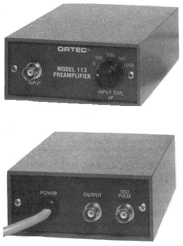
7 1 ORTEC MODEL 113 SCINTILLATION PREAMPLIFIER 1. DESCRIPTION 1.1. GENERAL The ORTEC 113 Scintillation Preamplifier is an alltransistor preamplifier designed for use with photomultiplier tubes. It is a noninverting preamplifier with no provisions for pulse shaping except the variation of fall time. The 113 is intended to operate into a shaping-type amplifier such as the ORTEC 410. A diode network prevents destruction of the input transistor if a sudden positive or negative high voltage is applied to the input. 2. SPECIFICATIONS RISE TIME <60 nsec. PERFORMANCE PREAMPLIFIER FALL TIME Fall time constant is designed for 50 :sec, assuming a signal source impedance of 1 MS. INTEGRAL NONLINEARITY #0.02%. TEMPERATURE COEFFICIENT ±0.01%/ C, 10 to 50 C. COUNTING RATE The gain shift of a 250-mV reference pulse is <0.25% with the application of an additional count rate of 65,000 counts/sec of 200- mv random pulses. CONTROL INPUT CAP pf Switch selects desired input capacity: 0, 100, 200, 500, 1000 pf. INPUT BNC connector; isolated for 1000 V; positive or negative polarity, 1 MS impedance shunted by 45 pf plus the capacity selected by switch S1 (0, 100, 200, 500, or 1000 pf). TEST PULSE BNC connector; accepts a pulse generator output with fast rise and slow decay to check operation of the electronics; input impedance 100S. ELECTRICAL AND MECHANICAL POWER REQUIRED +24 V dc, 17 ma;!24 V dc, 17 ma; supplied from any ORTEC transistor main amplifier or an ORTEC Preamplifier Power Supply through 10-ft captive cable. WEIGHT (Shipping) 2.3 lb (1.05 kg). WEIGHT (Net) 1.5 lb (0.68 kg). DIMENSIONS 1.75 x 4 x 6 in. (4.5 x 10.2 x 15.3 cm). RELATED EQUIPMENT The 113 can be operated with any ORTEC Shaping Main Amplifier. Test input pulses can be furnished from any ORTEC Pulse Generator. OUTPUT BNC connector; output impedance adjustable from 40 to 140S. Output saturation level ±10 V into open circuit; ±5.1 V into 100S load. Linear output ±7 V into open circuit; ±3.5 V into 100S load.
8 2 3. INSTALLATION INSTRUCTIONS 3.1. CONNECTION TO PHOTOMULTIPLIER TUBE Connect the output of the photomultiplier to the input of the 113 with a coaxial cable. This cable should be kept as short as practicable. The photomultiplier output can be taken from the anode, cathode, or any dynode and will generally be accoupled. The input connector of the 113 is isolated for 1000 V dc; however, it can be modified for 3000-V dc isolation by being replaced with a type SHV connector CONNECTION TO A SHAPING MAIN AMPLIFIER The 113 can be used to drive long lengths of 93S cable to a shaping amplifier and is designed to be directly compatible with ORTEC transistor main amplifiers. The output impedance of the 113 is 93S; therefore if the 93S cable is used, it is not necessary to terminate it at the receiving end. If unterminated cable is used on the output, with impedance other than 93S, resistor R24 should be adjusted for an output impedance equal to the value of the cable impedance to prevent pulse reflections INPUT POWER Power for the 113 is supplied through an Amphenol connector ( ) on the rear of the chassis. Power may be supplied by a single 45-V battery with a tap at 22.5 V (use the tap as ground, providing V and!22.5 V; current drain is 17 ma) or by any well-filtered ±24-V power supply such as the ORTEC 114 Preamplifier Power Supply. If the 113 is used with ORTEC transistor main amplifiers, power for the preamplifier can be supplied from the main amplifier through the interconnecting cable supplied with the TEST PULSE A voltage pulse can be inserted at the Test Pulse connector on the rear of the 113. The 113 has a built-in charge terminator that converts the input voltage to an input charge to simulate a charge pulse from the photomultiplier tube. The shape of the voltage test pulse should have a fast rise time (less than 10-8 sec) followed by a slow expoential decay back to the baseline (2 to 4 X 10⁻⁴ sec). A 1-V input signal at the Test Pulse connector produces a pulse of approximately 135 mv when an input capacity of 100 pf is selected by S1. 4. OPERATING INSTRUCTIONS The shape of the output pulse from the photomultiplier tube is dependent on the form of the light pulse, the transit-time spread in the photomultiplier, and the anode resistance and capacitance. Since the form of the light pulse and the transit time of the tube cannot be altered, our concern is with the anode and associated circuitry. The signal at the anode appears as a current pulse or a quantity of charge, and the voltage produced by this quantity of charge is given by Q V = C, where C = C s + C in (see Fig. 4.1). (C 1 and C 2 are coupling capacitors that are large in value compared to C, and therefore accumulate a negligible amount of voltage from the charge transferred.) The voltage developed across C s + C in will decay with a time constant of J f = R J C, where and R s = high-voltage supply output resistance. R τ R = R in in ( R + R + R s ) + R s,
9 3 From the above equations it can be seen that the pulse amplitude can be varied by varying C in, which can be varied by steps with switch S1 on the front panel. The input capacity of the 113 is approximately 45 pf plus the capacity selected by S1. R in was selected to produce a fall time constant of 50 :sec, assuming a driving source impedance of 1 X 10 6 S. If a pole-zero-cancelled amplifier is used following the 113, it will be necessary to adjust the pole-zero trim on the amplifier each time a different input capacitance is selected for the 113. Fig Functional Diagram of the 113 Preamplifier. 5. MAINTENANCE INSTRUCTIONS 5.1. TESTING PERFORMANCE Insert a voltage pulse in the Input connector and monitor the output with an oscilloscope. The output pulse should be equal to the input pulse when the output is not loaded and equal to one-half the input pulse when it is loaded with 93S and R16 plus R24 is equal to 93S. Perform this test with both positive and negative input pulses. Insert a voltage pulse into the Test Pulse input connector and monitor the output pulse with an oscilloscope. For each volt input an output voltage of approximately 135 mv should be obtained when an input capacity of 100 pf is selected by S1. The output pulse should decrease in amplitude as the input capacity is increased SUGGESTIONS FOR TROUBLESHOOTING Perform the tests outlined in Section 5.1. If an output pulse of the proper magnitude is not obtained, check all dc voltages and compare them with the values tabulated below DC VOLTAGES The voltages listed below will help to locate defective components. All voltages are measured with respect to ground. LOCATION Typical dc Voltages DC VOLTAGES +24 V Supply V Supply - 24 Q1e Q1b Q1c Q2e Q2c Q3e Q3b FACTORY REPAIR This instrument can be returned to the ORTEC factory for service and repair at a nominal cost. Our standard procedure for repair ensures the same quality control and checkout that are used for a new instrument. Always contact Customer Services at ORTEC, (865) , before sending in an instrument for repair to obtain shipping instructions and so that the required Return Authorization Number can be assigned to the unit. Write this number on the address label and on the package to ensure prompt attention when it reaches the ORTEC factory.
Model 9305 Fast Preamplifier Operating and Service Manual
 Model 9305 Fast Preamplifier Operating and Service Manual This manual applies to instruments marked Rev 03" on rear panel. Printed in U.S.A. ORTEC Part No.605540 1202 Manual Revision B Advanced Measurement
Model 9302 Amplifier-Discriminator Operating and Service Manual
 Model 9302 Amplifier-Discriminator Operating and Service Manual Printed in U.S.A. ORTEC Part No. 733690 1202 Manual Revision C Advanced Measurement Technology, Inc. a/k/a/ ORTEC, a subsidiary of AMETEK,
Model 863 Quad Timing Filter Amplifier Operating and Service Manual
 Model 863 Quad Timing Filter Amplifier Operating and Service Manual Printed in U.S.A. ORTEC Part No. 733960 0411 Manual Revision C Advanced Measurement Technology, Inc. a/k/a/ ORTEC, a subsidiary of AMETEK,
Model 533 Dual Sum and Invert Amplifier Operating and Service Manual
 Model 533 Dual Sum and Invert Amplifier Operating and Service Manual Printed in U.S.A. ORTEC Part No. 733410 1202 Manual Revision B Advanced Measurement Technology, Inc. a/k/a/ ORTEC, a subsidiary of AMETEK,
Model 416A Gate and Delay Generator Operating and Service Manual
 Model 416A Gate and Delay Generator Operating and Service Manual Printed in U.S.A. ORTEC Part No. 733160 1202 Manual Revision E Advanced Measurement Technology, Inc. a/k/a/ ORTEC, a subsidiary of AMETEK,
ScintiPack Model 296 Photomultiplier Base with Preamplifier and High Voltage Power Supply Operating and Service Manual
 ScintiPack Model 296 Photomultiplier Base with Preamplifier and High Voltage Power Supply Operating and Service Manual WARNING This equipment generates, uses, and can radiate radio frequency energy, and
Model 427A Delay Amplifier Operating and Service Manual
 Model 427A Delay Amplifier Operating and Service Manual This manual Applies to instruments marked Rev 22" on rear panel Printed in U.S.A. ORTEC Part No. 733210 1202 Manual Revision B Advanced Measurement
Model 428 Detector Bias Supply Operating and Service Manual
 Model 428 Detector Bias Supply Operating and Service Manual Printed in U.S.A. ORTEC Part No. 733220 1202 Manual Revision C Advanced Measurement Technology, Inc. a/k/a/ ORTEC, a subsidiary of AMETEK, Inc.
Model 426 Linear Gate Operating and Service Manual
 Model 426 Linear Gate Operating and Service Manual This manual applies to instruments marked Rev 23" on rear panel Printed in U.S.A. ORTEC Part No. 733200 1202 Manual Revision B Advanced Measurement Technology,
Model 276L Low-Power Photomultiplier Base Operating and Service Manual
 Model 276L Low-Power Photomultiplier Base Operating and Service Manual Printed in U.S.A. ORTEC Part No. 762870 0702 Manual Revision C $GYDQFHG 0HDVXUHPHQW 7HFKQRORJ\,QF a/k/a/ ORTEC, a subsidiary of AMETEK,
Model 449 Log/Lin Ratemeter Operating and Service Manual
 Model 449 Log/Lin Ratemeter Operating and Service Manual Printed in U.S.A. ORTEC Part No. 733270 1202 Manual Revision D Advanced Measurement Technology, Inc. a/k/a/ ORTEC, a subsidiary of AMETEK, Inc.
Model 439 Digital Current Integrator Operating Manual
 Model 439 Digital Current Integrator Operating Manual Printed in U.S.A. ORTEC Part No. 733240 0908 Manual Revision K Advanced Measurement Technology, Inc. a/k/a/ ORTEC, a subsidiary of AMETEK, Inc. WARRANTY
Model 480 Pulser Operating and Service Manual
 Model 480 Pulser Operating and Service Manual Printed in U.S.A. ORTEC Part No. 733390 1202 Manual Revision B Advanced Measurement Technology, Inc. a/k/a/ ORTEC, a subsidiary of AMETEK, Inc. WARRANTY ORTEC*
Model 542 Linear Gate and Stretcher Operating and Service Manual
 Model 542 Linear Gate and Stretcher Operating and Service Manual NOTE: A substitution for the dual diode package (MSD6100) may have been made in this unit. If so, two 1N4153 diodes were used to replace
Model 142AH Preamplifier Operating and Service Manual
 Model 142AH Preamplifier Operating and Service Manual Printed in U.S.A. ORTEC Part No. 733990 0202 Manual Revision B $GYDQFHG 0HDVXUHPHQW 7HFKQRORJ\,QF a/k/a/ ORTEC, a subsidiary of AMETEK, Inc. WARRANTY
Model 9307 pico-timing Discriminator Operating and Service Manual
 Model 9307 pico-timing Discriminator Operating and Service Manual Printed in U.S.A. ORTEC Part No. 764020 1202 Manual Revision C Advanced Measurement Technology, Inc. a/k/a/ ORTEC, a subsidiary of AMETEK,
Model 935 Quad Constant-Fraction 200-MHz Discriminator Operating and Service Manual
 Model 935 Quad Constant-Fraction 200-MHz Discriminator Operating and Service Manual U.S. Patent No. 4,179,644 Printed in U.S.A. ORTEC Part No. 753770 0503 Manual Revision H ii $GYDQFHG0HDVXUHPHQW7HFKQRORJ\,QF
Model 566 Time-to-Amplitude Converter (TAC) Operating and Service Manual
 Operating and Service Manual") Model 566 Time-to-Amplitude Converter (TAC) Operating and Service Manual Printed in U.S.A. ORTEC Part No. 678950 0411 Manual Revision F Advanced Measurement Technology, Inc. a/k/a/ ORTEC, a subsidiary
Model 566 Time-to-Amplitude Converter (TAC) Operating and Service Manual Printed in U.S.A. ORTEC Part No. 678950 0411 Manual Revision F Advanced Measurement Technology, Inc. a/k/a/ ORTEC, a subsidiary
2001A. 200KHz Function Generator Instruction Manual. 99 Washington Street Melrose, MA Phone Toll Free
 2001A 200KHz Function Generator Instruction Manual 99 Washington Street Melrose, MA 02176 Phone 781-665-1400 Toll Free 1-800-517-8431 Visit us at www.testequipmentdepot.com WARRANTY Global Specialties
Model 460 Delay Line Amplifier Operating and Service Manual
 Model 460 Delay Line Amplifier Operating and Service Manual Printed in U.S.A. ORTEC Part No. 733320 1202 Manual Revision C Advanced Measurement Technology, Inc. a/k/a/ ORTEC, a subsidiary of AMETEK, Inc.
PCO-7114 Laser Diode Driver Module Operation Manual
 PCO-7114 Laser Diode Driver Module Operation Manual Directed Energy, Inc. 1609 Oakridge Dr., Suite 100, Fort Collins, CO 80525, (970) 493-1901 sales@ixyscolorado.com www.ixyscolorado.com Manual Document
Glass Electrode Meter
 Glass Electrode Meter INSTRUCTION MANUAL FOR Glass Electrode R/C Meter MODEL 2700 Serial # Date PO Box 850 Carlsborg, WA 98324 U.S.A. 360-683-8300 800-426-1306 FAX: 360-683-3525 http://www.a-msystems.com
305 Stimulus Isolator. Description
 Description The Model 305 Stimulus Isolator utilizes photon coupling to provide nearly ideal isolation of the pulse and train outputs of the WPI Series 300 Anapulse Stimulators. Two Model 305 units are
INSTRUCTION MANUAL. March 11, 2003, Revision 3
 INSTRUCTION MANUAL Model 701A Stimulator March 11, 2003, Revision 3 Copyright 2003 Aurora Scientific Inc. Aurora Scientific Inc. 360 Industrial Parkway S., Unit 4 Aurora, Ontario, Canada L4G 3V7 Tel: 1-905-727-5161
Wilcom MODEL T136BSBZW CIRCUIT TEST SET. Operating Instructions
 Wilcom MODEL T136BSBZW CIRCUIT TEST SET Operating Instructions T136BSB Current Test Set Operating Instructions 811-230-007 February 2007 Copyright (c) 2007 Wilcom All Rights reserved Wilcom reserves the
DUAL CHANNEL BROADBAND LINEAR AMPLIFIER Model A800D
 DUAL CHANNEL BROADBAND LINEAR AMPLIFIER Model A800D HIGH VOLTAGE FIXED GAIN BROADBAND 800Vpp 60mA 100x DC to ca 200 khz LOW OUTPUT IMPEDANCE HIGH SLEW RATE
SSR-150xxx-40VL-12P-xC-xxxCS
 HELLROARING TECHNOLOGIES, INC. P.O. BOX 1521 POLSON, MT 59860 406 883-3801 HTTP://WWW.HELLROARING.COM SUPPORT@HELLROARING.COM SSR-150xxx-40VL-12P-xC-xxxCS The SSR-150xxx-40VL-12P-xC-xxxCS is designed for
Model 7000 Low Noise Differential Preamplifier
 Model 7000 Low Noise Differential Preamplifier Operating Manual Service and Warranty Krohn-Hite Instruments are designed and manufactured in accordance with sound engineering practices and should give
LUDLUM MODEL 182 RADON FLASK COUNTER. June 2011 Serial Number PR and Succeeding Serial Numbers
 LUDLUM MODEL 182 RADON FLASK COUNTER June 2011 Serial Number PR206794 and Succeeding Serial Numbers LUDLUM MODEL 182 RADON FLASK COUNTER June 2011 Serial Number PR206794 and Succeeding Serial Numbers LUDLUM
2015 RIGOL TECHNOLOGIES, INC.
 Service Guide DG000 Series Dual-channel Function/Arbitrary Waveform Generator Oct. 205 TECHNOLOGIES, INC. Guaranty and Declaration Copyright 203 TECHNOLOGIES, INC. All Rights Reserved. Trademark Information
Wilcom MODEL T136BGMZW CIRCUIT TEST SET. Operating Instructions
 Wilcom MODEL T136BGMZW CIRCUIT TEST SET Operating Instructions T136BGM Current Test Set Operating Instructions 811-233-010 February 2007 Copyright (c) 2007 Wilcom All Rights reserved Wilcom reserves the
LUDLUM MODEL 421 AND PMT BASE WITH PREAMPLIFIER/BIAS SUPPLY. October 2014 Serial Number and Succeeding Serial Numbers
 LUDLUM MODEL 421 AND 421-3 PMT BASE WITH PREAMPLIFIER/BIAS SUPPLY October 2014 Serial Number 200000 and Succeeding Serial Numbers LUDLUM MODEL 421 AND 421-3 PMT BASE WITH PREAMPLIFIER/BIAS SUPPLY October
User Manual. Smart-UPS On-Line. Uninterruptible Power Supply. Isolation Transformer Models: SURT001 and SURT002
 User Manual Smart-UPS On-Line Uninterruptible Power Supply Isolation Transformer Models: SURT001 and SURT002 Isolation and Step-Down Transformer Models: SURT003 and SURT004 General Information Important
SSR VL-12P-xC-NCS
 HELLROARING TECHNOLOGIES, INC. P.O. BOX 1521 POLSON, MT 59860 406 883-3801 HTTP://WWW.HELLROARING.COM SUPPORT@HELLROARING.COM SSR-40150-200VL-12P-xC-NCS The SSR-40150-200VL-12P-xC-NCS is designed for Low
BROADBAND'LINEAR'AMPLIFIER WITH'A±B'INPUTS'AND'DC5OFFSET Model&A400X
 ELECTRONICS AB BROADBAND'LINEAR'AMPLIFIER WITH'A±B'INPUTS'AND'DC5OFFSET ModelA400X HIGHVOLTAGE FIXEDGAIN BROADBAND ±200V 150mA 20x DCtoca500kHz FULLSCALE LOWOUTPUTIMPEDANCE HIGHSLEWRATE
Broadband Step-Up Transformer. User Manual
 Broadband Step-Up Transformer User Manual 990-1930 09/2004 Introduction Introduction About this unit The APC Step-Up Transformer provides 220 V power from 60 VAC Broadband cable systems. Safety Electrical
P5100A & P5150 High Voltage Probes Performance Verification and Adjustments
 x P5100A & P5150 High Voltage Probes Performance Verification and Adjustments ZZZ Technical Reference *P077053001* 077-0530-01 xx P5100A & P5150 High Voltage Probes Performance Verification and Adjustments
DUAL%CHANNEL%LINEAR%AMPLIFIER %WITH%PHASE%INVERTER Model&A400DI
 ELECTRONICS AB DUAL%CHANNEL%LINEAR%AMPLIFIER %WITH%PHASE%INVERTER ModelA400DI HIGHVOLTAGE FIXEDGAIN BROADBAND ±200V 150mA 20x DCtoca500kHz FULLSCALE LOWOUTPUTIMPEDANCE HIGHSLEWRATE
742A Series Resistance Standards
 742A Series Resistance Standards Instruction Manual PN 850255 September 1988 Rev. 1, 4/89 1988-2015 Fluke Corporation. All rights reserved. All product names are trademarks of their respective companies.
Model 673 Spectroscopy Amplifier and Gated Integrator Operating and Service Manual
 Model 673 Spectroscopy Amplifier and Gated Integrator Operating and Service Manual Printed in U.S.A. ORTEC Part No. 675590 0202 Manual Revision B $GYDQFHG 0HDVXUHPHQW 7HFKQRORJ\,QF a/k/a/ ORTEC, a subsidiary
BROADBAND'LINEAR'AMPLIFIER Model&F10AD
 BROADBAND'LINEAR'AMPLIFIER Model&F10AD DUAL'CHANNEL & HIGH&VOLTAGE& FIXED&GAIN& BROADBAND & ±100V&185mA& 10x& DC&to&ca&1&MHz & HIGH&SLEW&RATE& LOW&OUTPUT&IMPEDANCE & 400&V/µs&
BROADBAND LINEAR AMPLIFIER Model P150
 ELECTRONICS AB BROADBAND LINEAR AMPLIFIER Model P150 HIGH VOLTAGE GAIN HIGH CURRENT +150V 20x 1A HIGH POWER SMALL SIGNAL SLEW RATE BANDWIDTH BANDWIDTH 30 V/µs DC to ca 60 khz DC to >200 khz FLC Electronics
Radio Remote Controls Manual K Series
 Radio Remote Controls Manual K Series PN 52764 2010.12.20 Rev. 2 K Series radio control manual 1 Conductix Incorporated The technical data and images which appear in this manual are for informational purposes
PDB4. Four Channel Passive Direct Box USER'S GUIDE
 PDB4 Four Channel Passive Direct Box USER'S GUIDE IMPORTANT SAFETY INSTRUCTIONS - READ FIRST This symbol, wherever it appears, alerts you to important operating and maintenance instructions in the accompanying
201AP Charge Amplifier User Manual
 Trig-Tek 201AP Charge Amplifier User Manual Publication No. 980996 Rev. A Astronics Test Systems Inc. 4 Goodyear, Irvine, CA 92618 Tel: (800) 722-2528, (949) 859-8999; Fax: (949) 859-7139 atsinfo@astronics.com
TRANSDUCER IN-LINE AMPLIFIER
 TRANSDUCER IN-LINE Bi-Polar Model AMPLIFIER 2080 Arlingate Lane, Columbus, Ohio 43228 (614) 850-5000 Sensotec, Inc. 2080 Arlingate Lane Columbus, Ohio 43228 Copyright 1995 by Sensotec, Inc. all rights
Model 5100F. Advanced Test Equipment Rentals ATEC (2832) OWNER S MANUAL RF POWER AMPLIFIER
 OWNER S MANUAL RF POWER AMPLIFIER") Established 1981 Advanced Test Equipment Rentals www.atecorp.com 800-404-ATEC (2832) OWNER S MANUAL Model 5100F RF POWER AMPLIFIER 0.8 2.5 GHz, 25 Watts Ophir RF 5300 Beethoven Street Los Angeles, CA 90066
Established 1981 Advanced Test Equipment Rentals www.atecorp.com 800-404-ATEC (2832) OWNER S MANUAL Model 5100F RF POWER AMPLIFIER 0.8 2.5 GHz, 25 Watts Ophir RF 5300 Beethoven Street Los Angeles, CA 90066
TRANSDUCER IN-LINE AMPLIFIER
 TRANSDUCER IN-LINE Voltage Model AMPLIFIER 2080 Arlingate, Columbus, Ohio 43228, (614) 850-5000 Sensotec, Inc. 2080 Arlingate Lane Columbus, Ohio 43228 Copyright 1995 by Sensotec, Inc. all rights reserved
Log Periodic Antenna
 Page 1 of 10 Log Periodic Antenna ALFM 80120 88 MHz to 108 MHz (Extendible to 80 to 120 MHz) Page 2 of 10 Table of Contents 1.0 Introduction... 3 2.0 Product Specifications... 4 3.0 Important Safety Precautions...
Model 1791 VHF Radio User's Manual
 Model 79 VHF Radio User's Manual ALL WEATHER INC 65 NATIONAL DRIVE SACRAMENTO, CA 95834 WWW.ALWEATHERINC.COM 79 VHF RADIO USER'S MANUAL CONTENTS INTRODUCTION... Description... Transmitter Module... Power
PHASE ROTATION METER. Operating and Instruction Manual. a n d A C C E S S O R I E S
 PHASE ROTATION METER a n d A C C E S S O R I E S Operating and Instruction Manual HD ELECTRIC COMPANY 1 4 7 5 L A K E S I D E D R I V E WA U K E G A N, I L L I N O I S 6 0 0 8 5 U. S. A. PHONE 847.473.4980
BROADBAND LINEAR AMPLIFIER Model F1020 (models F10A and F20A combined)
") BROADBAND LINEAR AMPLIFIER Model F1020 (models F10A and F20A combined) HIGH VOLTAGE FIXED GAIN BROADBAND ±100V 185mA/±150V 150mA 10x/20x DC to ca 1 MHz HIGH SLEW RATE LOW OUTPUT IMPEDANCE 300 V/µs
BROADBAND LINEAR AMPLIFIER Model F1020 (models F10A and F20A combined) HIGH VOLTAGE FIXED GAIN BROADBAND ±100V 185mA/±150V 150mA 10x/20x DC to ca 1 MHz HIGH SLEW RATE LOW OUTPUT IMPEDANCE 300 V/µs
INSTALLATION GUIDE. Video Balun Transceiver with fixed BNC for twisted pair operation with other balun transceivers or active receivers.
 INSTALLATION GUIDE VB37M Video Balun Transceiver for Twisted Pair Description Video Balun Transceiver with fixed BNC for twisted pair operation with other balun transceivers or active receivers. The VB37M
Owner s Manual ODYSSEY BENCH MODEL. O4100B shown REV E. Southern Avenue, Phoenix, AZ USA Workhorseproducts.
 Owner s Manual ODYSSEY BENCH MODEL O4100B shown 67-1375 REV 218 3730 E. Southern Avenue, Phoenix, AZ 85040 USA 800-778-8779 Workhorseproducts.com 1 Table of Contents I. Introduction & Safety Information.
34134A AC/DC DMM Current Probe. User s Guide. Publication number April 2009
 User s Guide Publication number 34134-90001 April 2009 For Safety information, Warranties, Regulatory information, and publishing information, see the pages at the back of this book. Copyright Agilent
User s Guide. RP7000 Series Active Probe. Dec RIGOL Technologies, Inc.
 User s Guide RP7000 Series Active Probe Dec. 2012 RIGOL Technologies, Inc. Guaranty and Declaration Copyright 2011 RIGOL Technologies, Inc. All Rights Reserved. Trademark Information RIGOL is a registered
AMP-13 OPERATOR S MANUAL
 AMP-13 OPERATOR S MANUAL Version 2.0 Copyright 2008 by Vatell Corporation Vatell Corporation P.O. Box 66 Christiansburg, VA 24068 Phone: (540) 961-3576 Fax: (540) 953-3010 WARNING: Read instructions carefully
CURRENT MEARUREMENT SHUNT CS-10/500 USER MANUAL
 CURRENT MEARUREMENT SHUNT CS-10/500 USER MANUAL 2017 Megaimpulse Ltd. Copyright 2017 MEGAIMPULSE Ltd. All Rights Reserved. MEGAIMPULSE LTD. PROVIDES THIS MANUAL "AS IS" WITHOUT WARRANTY OF ANY KIND, EITHER
Signal Isolation Module. Instruction Manual SIM
 Signal Isolation Module Instruction Manual SIM200-000 Table of Contents 1. General Description... 3 2. Specifications... 3 2.1 Electrical... 3 2.2 Physical... 4 3. Installation... 4 3.1 Wiring Guidelines...
Directed Energy, Inc Oakridge Dr., Suite 100, Fort Collins, CO
 PCO-7121 Laser Diode Driver Module Operation Manual Directed Energy, Inc. 1609 Oakridge Dr., Suite 100, Fort Collins, CO 80525 sales@ixyscolorado.com www.ixyscolorado.com Contents Contents... 3 Safety...
P5100A & P5150 High Voltage Probes Performance Verification and Adjustments
 x P5100A & P5150 High Voltage Probes Performance Verification and Adjustments ZZZ Technical Reference *P077053002* 077-0530-02 xx P5100A & P5150 High Voltage Probes Performance Verification and Adjustments
DC200A Displacement Clipper User Manual
 Trig-Tek DC200A Displacement Clipper User Manual Publication No. 980981 A Inc. 4 Goodyear, Irvine, CA 92618 Tel: (800) 722-2528, (949) 859-8999; Fax: (949) 859-7139 atsinfo@astronics.com atssales@astronics.com
BC145 SIGNAL ISOLATOR BOARD
 BC145 SIGNAL ISOLATOR BOARD 4/17 Installation & Operating Manual MN1373 Any trademarks used in this manual are the property of their respective owners. Important: Be sure to check www.baldor.com to download
Current Probes. User Manual
 Current Probes User Manual ETS-Lindgren Inc. reserves the right to make changes to any product described herein in order to improve function, design, or for any other reason. Nothing contained herein shall
INSTRUCTION MANUAL. Model Autoranging DMM ProbeMeter TM. Measures voltage, resistance, frequency, capacitance, temperature, and duty cycle.
 INSTRUCTION MANUAL Model 403380 Autoranging DMM ProbeMeter TM Measures voltage, resistance, frequency, capacitance, temperature, and duty cycle. Back lit LCD with Autorange and full function displays Audible
DYNAMIC ENGINEERING 435 Park Dr., Ben Lomond, Calif Fax Est.
 DYNAMIC ENGINEERING 435 Park Dr., Ben Lomond, Calif. 95005 831-336-8891 Fax 831-336-3840 http://www.dyneng.com sales@dyneng.com Est. 1988 User Manual PIM-Parallel-IO PMC IO Module for PMC Parallel IO PIM
Model 855 Dual Spectroscopy Amplifier Operating and Service Manual
 Model 855 Dual Spectroscopy Amplifier Operating and Service Manual This manual applies to instruments marked Rev. 03" on rear panel. Printed in U.S.A. ORTEC Part No. 717490 0406 Manual Revision C $GYDQFHG0HDVXUHPHQW7HFKQRORJ\,QF
ECG PATIENT SIMULATOR FIVE LEAD
 ECG PATIENT SIMULATOR FIVE LEAD PS-2005 USER MANUAL BC BIOMEDICAL PS-2005 TABLE OF CONTENTS WARNINGS, CAUTIONS, NOTICES... ii DESCRIPTION... 1 LAYOUT... 2 MANUAL REVISIONS... 6 LIMITED WARRANTY... 6 SPECIFICATIONS...
Smart-UPS On-Line Isolation and Step-Down Transformer SRT5KTF
 Smart-UPS On-Line Isolation and Step-Down Transformer SRT5KTF Safety Messages Read the instructions carefully to become familiar with the equipment before attempting to install, operate, service or maintain
Questions? Call Toll-Free
 List Instruction Manual & Parts IMPORTANT! PLEASE READ INSTRUCTIONS CAREFULLY Failure to install and operate MAC products according to our specified instructions could result in equipment malfunction or
12B/18 MultiMeter Instruction Sheet
 12B/18 MultiMeter Instruction Sheet P Read First: Safety Information To ensure that the meter is used safely, follow these instructions: Do not use the meter if the meter or test leads appear damaged,
Current Probe Fixture Instruction Manual
 Current Probe Fixture Instruction Manual 1 TABLE OF CONTENTS INTRODUCTION 3 GENERAL INFORMATION 4 TEST METHODS 5 SAFETY 7 FIGURES 8 FORMULAS 10 MAINTENANCE 11 WARRANTY 12 2 INTRODUCTION figure 1 Mechanical
200B Clipper Module User Manual
 Trig-Tek 200B Clipper Module User Manual Publication No. 980954 Rev. A Astronics Test Systems Inc. 4 Goodyear, Irvine, CA 92618 Tel: (800) 722-2528, (949) 859-8999; Fax: (949) 859-7139 atsinfo@astronics.com
Preliminary Data Sheet!
 HELLROARING TECHNOLOGIES, INC. P.O. BOX 1521 POLSON, MT 59860 406 883-3801 HTTP://WWW.HELLROARING.COM SALES11@HELLROARING.COM SSD-100200-1200V-XP-XC Preliminary Data Sheet! The SSD-100200-1200V-XP-TTL
Owner s Manual & Safety Instructions
 Owner s Manual & Safety Instructions Save This Manual Keep this manual for the safety warnings and precautions, assembly, operating, inspection, maintenance and cleaning procedures. Write the product s
MODEL 3810/2 Line Impedance Stabilization Network
 EMC TEST SYSTEMS FEBRUARY 1996 REV C PN 399197 MODEL 3810/2 Line Impedance Stabilization Network OPERATION MANUAL USA P.O. Box 80589 Austin, Texas 78708-0589 2205 Kramer Lane, Austin, Texas 78758-4047
OPERATION & SERVICE MANUAL FOR FC 110 AC POWER SOURCE
 OPERATION & SERVICE MANUAL FOR FC 100 SERIES AC POWER SOURCE FC 110 AC POWER SOURCE VERSION 1.3, April 2001. copyright reserved. DWG No. FC00001 TABLE OF CONTENTS CHAPTER 1 INTRODUCTION... 1 1.1 GENERAL...
INSTALLATION AND MAINTENANCE MANUAL FOR GROUND MONITOR GM-250 COPYRIGHT 1983 AMERICAN MINE RESEARCH, INC.
 INSTALLATION AND MAINTENANCE MANUAL FOR GROUND MONITOR GM-250 COPYRIGHT 1983 AMERICAN MINE RESEARCH, INC. MANUAL PART NUMBER 180-0036 ORIGINAL: 1-17-83 REVISION: B (8-26-86) NOT TO BE CHANGED WITHOUT MSHA
INSTRUCTION MANUAL UTL260
 INSTRUCTION MANUAL UTL260 1-800-547-5740 Fax: (503) 643-6322 www.ueitest.com email: info@ueitest.com Introduction The UTL260 has all the features and measurement functions that appliance technicians need.
41P Portable Calibrator User Manual
 Trig-Tek 41P Portable Calibrator User Manual Publication No. 980961 Rev. A Astronics Test Systems Inc. 4 Goodyear, Irvine, CA 92618 Tel: (800) 722-2528, (949) 859-8999; Fax: (949) 859-7139 atsinfo@astronics.com
ECG PATIENT SIMULATOR SIX LEAD
 ECG PATIENT SIMULATOR SIX LEAD PS-2006 USER MANUAL BC BIOMEDICAL PS-2006 TABLE OF CONTENTS WARNINGS, CAUTIONS, NOTICES... ii DESCRIPTION... 1 LAYOUT... 2 MANUAL REVISIONS... 6 LIMITED WARRANTY... 6 SPECIFICATIONS...
LUDLUM MODEL MODEL AND MODEL GAMMA SCINTILLATORS. June 2017
 LUDLUM MODEL 44-20 MODEL 44-20-1 AND MODEL 44-20-3 GAMMA SCINTILLATORS June 2017 LUDLUM MODEL 44-20 MODEL 44-20-1 AND MODEL 44-20-3 GAMMA SCINTILLATORS June 2017 STATEMENT OF WARRANTY Ludlum Measurements,
TETRIS User's Guide. High Impedance Active Probe DO177-1
 TETRIS 1500 High Impedance Active Probe User's Guide DO177-1 TETRIS 1500 Copyright 2010 Ltd. All rights reserved. Information in this publication supersedes that in all previously published material. Specifications
ELECTROSURGICAL UNIT ANALYZER
 ELECTROSURGICAL UNIT ANALYZER ESU-2000A USER MANUAL BC BIOMEDICAL ESU-2000A TABLE OF CONTENTS WARNINGS, CAUTIONS, NOTICES... ii DESCRIPTION... 1 OVERVIEW... 2 OPERATING INSTRUCTIONS... 3 MANUAL REVISIONS...
Model 3210C. 100 Ampere AC Current Standard. Operating Manual
 Model 3210C 100 Ampere AC Current Standard Operating Manual This page intentionally left blank. 3210C OPERATORS MANUAL Serial No. Win-man\3210C.wpd This page intentionally left blank. 3210C OPERATORS MANUAL
TA MHz oscilloscope probe TA MHz oscilloscope probe
 TA375 100 MHz oscilloscope probe TA386 200 MHz oscilloscope probe User's Guide X1 X10 TA386 X1/X10 Max. 600 Vp Introduction This passive high-impedance oscilloscope probe is suitable for most oscilloscopes
DA560D COMPACT SERIES. INSTALLATION / OWNER'S MANUAL Mobile Power Amplifiers
 DA560D COMPACT SERIES INSTALLATION / OWNER'S MANUAL Mobile Power Amplifiers Preparation Please read entire manual before installation. Due to the technical nature of amplifiers, it is highly recommended
SX204. Headphone Amplifier. Symetrix. Owner s Manual
 Symetrix SX204 Headphone Amplifier Owner s Manual Symetrix Inc. 14926 35th Avenue West Lynnwood, Washington 98037 Voice: (206) 787-3222, (800) 288-8855 Fax: (206) 787-3211 Copyright 1988, 1994 Symetrix
User s Guide. Agilent 16441A R-Box. Agilent Part No Printed in Japan January Edition 4
 User s Guide Agilent 16441A R-Box Agilent Part No. 16441-90000 Printed in Japan January 2000 Edition 4 Legal Notice The information contained in this document is subject to change without notice. Copyright
Model MV106J/MV116J. ±10nVdc to ±11Vdc Precision DC Voltage Standard Source. Operating Manual
 Model MV106J/MV116J ±10nVdc to ±11Vdc Precision DC Voltage Standard Source Operating Manual This page intentionally left blank. MV 106 & MV116 OPERATORS MANUAL Serial No. Win-man\mvman.wpd This page intentionally
INSTRUCTION MANUAL FOR CELL SIMULATOR MODEL 2410
 Cell Simulator INSTRUCTION MANUAL FOR CELL SIMULATOR MODEL 2410 A-M Systems PO Box 850 Carlsborg, WA 98324 U.S.A. 360-683-8300 800-426-1306 FAX: 360-683-3525 http://www.a-msystems.com Disclaimer THIS EQUIPMENT
XPR522 XPR540. XPR SERIES INSTALLATION / OWNER'S MANUAL Mobile Power Amplifiers
 XPR522 XPR540 XPR SERIES INSTALLATION / OWNER'S MANUAL Mobile Power Amplifiers Preparation Please read entire manual before installation. Due to the technical nature of amplifiers, it is highly recommended
Advanced Test Equipment Rentals ATEC (2832)
") Established 1981 Advanced Test Equipment Rentals www.atecorp.com 800-404-ATEC (2832) A.H. Systems Model Active Monopole Antennas Active Monopole Antenna Series Operation Manual 1 TABLE OF CONTENTS INTRODUCTION
Established 1981 Advanced Test Equipment Rentals www.atecorp.com 800-404-ATEC (2832) A.H. Systems Model Active Monopole Antennas Active Monopole Antenna Series Operation Manual 1 TABLE OF CONTENTS INTRODUCTION
DA6002D-DA10004D. INSTALLATION / OWNER'S MANUAL Mobile Power Amplifiers
 DA6002D-DA10004D INSTALLATION / OWNER'S MANUAL Mobile Power Amplifiers Preparation Please read entire manual before installation. Due to the technical nature of amplifiers, it is highly recommended that
MG5223F S-Band Magnetron
 MG5223F S-Band Magnetron The data should be read in conjunction with the Magnetron Preamble. ABRIDGED DATA Fixed frequency pulse magnetron. Operating frequency... 3050 ± 10 MHz Typical peak output power...
Amplified High Speed Photodetectors
 Amplified High Speed Photodetectors User Guide 3340 Parkland Ct. Traverse City, MI 49686 USA Page 1 of 6 Thank you for purchasing your Amplified High Speed Photodetector from EOT. This user guide will
200Amp AC Clamp Meter + NCV Model MA250
 User's Guide 200Amp AC Clamp Meter + NCV Model MA250 Introduction Congratulations on your purchase of this Extech MA250 Clamp Meter. This meter measures AC Current, AC/DC Voltage, Resistance, Capacitance,
PULSE OXIMETRY SIMULATOR
 PULSE OXIMETRY SIMULATOR SPO-2000 SYSTEM USER MANUAL BC BIOMEDICAL SPO-2000 SYSTEM TABLE OF CONTENTS WARNINGS, CAUTIONS, NOTICES... ii DESCRIPTION... 1 LAYOUT... 2 KEYS... 3 LED INDICATORS... 4 OPERATIONS...
HTA125A/250A. Power Amplifiers. Installation & Use Manual
 HTA125A/250A Power Amplifiers Installation & Use Manual Specifications subject to change without notice. 2010 Bogen Communications, Inc. All rights reserved. 54-5832-04B 1011 NOTICE: Every effort was made
Operator s Manual. PP016 Passive Probe
 Operator s Manual PP016 Passive Probe 2017 Teledyne LeCroy, Inc. All rights reserved. Unauthorized duplication of Teledyne LeCroy documentation materials is strictly prohibited. Customers are permitted