Introduction to Digital Communications System
|
|
|
- Esther Louise Wilkerson
- 6 years ago
- Views:
Transcription


1 Introduction to Digital Communications System
2 Recommended Books Digital Communications / Fourth Edition (textbook) -- John G. Proakis, McGraw Hill Communication Systems / 4th Edition -- Simon Haykin, John Wiley & Sons, Inc. Digital Communications Fundamentals and Applications / 2nd Edition -- Bernard Sklar, Prentice Hall Principles of Communications / Fifth Edition -- Rodger E. Ziemer and William H. Tranter, John Wiley & Sons, Inc. Modern Digital and Analog Communication Systems -- B.P. Lathi, Holt, Rinehart and Winston, Inc. 2
3 Example of Communications System Local Loop Local Loop Local Loop Switch Transmission Equipment Central Office Switch Transmission Equipment Central Office Switch T1/E1 Facilities regenerator A/D Conversion (Digitization) T1/E1 Facilities regenerator A/D Conversion (Digitization) T1/E1 Facilities M U X SONET SDH Mobile Switching Center T1/E1 Facilities Base Station Transmission Equipment Central Office regenerator A/D Conversion (Digitization) Public Switched Telephone Network (PSTN) 3 Mobile Switching Center Base Station
4 Basic Digital Communication Nomenclature Textual Message: information comprised of a sequence of characters. Binary Digit (Bit): the fundamental information unit for all digital systems. Symbol (m i where i=1,2, M): for transmission of the bit stream; groups of k bits are combined to form new symbol from a finite set of M such symbols; M=2 k. Digital Waveform: voltage or current waveform representing a digital symbol. Data Rate: Symbol transmission is associated with a symbol duration T. Data rate R=k/T [bps]. Baud Rate: number of symbols transmitted per second [baud]. 4

5 Nomenclature Examples 5
6 Messages, Characters, and Symbols 6
7 Typical Digital Communications System From Other Sources Information Bits Source Bits Channel Bits Format Digital Input m i Digital Output mˆ i Source Encoding Encryption Channel Encoding Bit Stream Interleaving Multiplexing Modulation (t) s i Synchronization ˆ ( t) s i Frequency Spreading Digital Waveform Multiple Access TX RF PA C H A N N E L Format Source Decoding Decryption Channel Decoding Deinterleaving Demultiplexing Demodulation Frequency Despreading Multiple Access RX RF IF Information Sink Source Bits Optional Essential Channel Bits To Other Destinations 7
8 Format
9 Typical Digital Communications System From Other Sources Information Bits Source Bits Channel Bits Format Digital Input m i Digital Output mˆ i Source Encoding Encryption Channel Encoding Bit Stream Interleaving Multiplexing Modulation (t) s i Synchronization ˆ ( t) s i Frequency Spreading Digital Waveform Multiple Access TX RF PA C H A N N E L Format Source Decoding Decryption Channel Decoding Deinterleaving Demultiplexing Demodulation Frequency Despreading Multiple Access RX RF IF Information Sink Source Bits Optional Essential Channel Bits To Other Destinations 9


10 Formatting and Baseband Transmission 10
11 Sampling Theorem 11
12 Sampling Theorem Sampling Theorem: A bandlimited signal having no spectral components above f m hertz can be determined uniquely by values sampled at uniform intervals of T s seconds, where T S 1 2 f m or sampling rate f 2 In sample-and-hold operation, a switch and storage mechanism form a sequence of samples of the continuous input waveform. The output of the sampling process is called pulse amplitude modulation (PAM). S f m 12

 X δ (")
 T 13")
13 Sampling Theorem 1 X S ( f ) = X ( f ) X δ ( f ) = X ( f nfs ) T 13 S n=
14 Spectra for Various Sampling Rates 14


15 Natural Sampling 15
16 Pulse Code Modulation (PCM) PCM is the name given to the class of baseband signals obtained from the quantized PAM signals by encoding each quantized sample into a digital word. The source information is sampled and quantized to one of L levels; then each quantized sample is digitally encoded into an l-bit (l=log 2 L) codeword. 16
17 Example of Constructing PCM Sequence 17


18 Uniform and Non-uniform Quantization 18

19 Statistical Distribution of Single-Talker Speech Amplitudes 50% of the time, speech voltage is less than ¼ RMS. Only 15% of the time, voltage exceeds RMS. Typical voice signal dynamic range is 40 db. 19
20 Problems with Linear Quantization Fact: Unacceptable S/N for small signals. Solution: Increasing quantization levels price is too high. Applying nonlinear quantization achieved by first distorting the original signal with a logarithmic compression characteristic and then using a uniform quantizer. At the receiver, an inverse compression characteristic, called expansion, is applied so that the overall transmission is not distorted. The processing pair is referred to as companding. 20


21 Implementation of Non-linear Quantizer 21
22 22 Companding Characteristics In North America: μ-law compression: In Europe: A-law compression: < + = + + = 0 for 1 0 for 1 sgn where sgn ) (1 log )] / ( [1 log max max x x x x x x y y e e µ µ < + + < + = 1 1 sgn log 1 )] / ( [ log sgn log 1 ) / ( max max max max max max x x A x A x x A y A x x x A x x A y y e e e

23 Compression Characteristics Standard values of μ is 255 and A is
24 Source Coding
25 Typical Digital Communications System From Other Sources Information Bits Source Bits Channel Bits Format Digital Input m i Digital Output mˆ i Source Encoding Encryption Channel Encoding Bit Stream Interleaving Multiplexing Modulation (t) s i Synchronization ˆ ( t) s i Frequency Spreading Digital Waveform Multiple Access TX RF PA C H A N N E L Format Source Decoding Decryption Channel Decoding Deinterleaving Demultiplexing Demodulation Frequency Despreading Multiple Access RX RF IF Information Sink Source Bits Optional Essential Channel Bits To Other Destinations 25
26 Source Coding Source coding deals with the task of forming efficient descriptions of information sources. For discrete sources, the ability to form reduced data rate descriptions is related to the information content and the statistical correlation among the source symbols. For analog sources, the ability to form reduced data rate descriptions, subject to a fixed fidelity criterion I related to the amplitude distribution and the temporal correlation of the source waveforms. 26
27 Huffman Coding The Huffman code is source code whose average word length approaches the fundamental limit set by the entropy of a discrete memoryless source. The Huffman code is optimum in the sense that no other uniquely decodable set of code-words has smaller average code-word length for a given discrete memoryless source. 27
28 Huffman Encoding Algorithm 1. The source symbols are listed in order of decreasing probability. The two source symbols of lowest probability are assigned a 0 and a These two source symbols are regarded as being combined into a new source symbol with probability equal to the sum of the two original probabilities. The probability of the new symbol is placed in the list in accordance with its value. 3. The procedure is repeated until we are left with a final list of source statistics of only two for which a 0 and a 1 are assigned. 4. The code for each (original) source symbol is found by working backward and tracing the sequence of 0s and 1s assigned to that symbol as well as its successors. 28
29 Symbol S0 S1 S2 S3 S4 Symbol Example of Huffman Coding Probability Stage 1 Code Word Stage 2 Stage 3 Stage 4 S0 S1 S2 S3 S
30 Properties of Huffman Code Huffman encoding process is not unique. Code words for different Huffman encoding process can have different lengths. However, the average code-word length is the same. When a combined symbol is moved as high as possible, the resulting Huffman code has a significantly smaller variance than when it is moved as low as possible. Huffman code is a prefix code. A prefix code is defined as a code in which no code-word is the prefix of any other code-word. 30
31 Bit Compression Technologies for Voice Differential PCM (DPCM) Adaptive DPCM Delta Modulation (DM) Adaptive DM (ADM)... Speech Encoding 31
32 Differential PCM (DPCM) 32

33 Delta Modulation (DM) Delta modulation is a one-bit DPCM. Advantage: bit compression. Disadvantage: slope overload. 33
34 Speech Coding Objective Reduce the number of bits needed to be transmitted, therefore lowering the bandwidth required. 34


35 Voiced Sound Speech Properties Arises in generation of vowels and latter portion of some consonants. Displays long-term repetitive pattern corresponding to the duration of a pitch interval Pulse-like waveform. Unvoiced Sound Arises in pronunciation of certain consonants such as s, f, p, j, x,, etc. Noise-like waveform. 35

36 Categories of Speech Encoding Waveform Encoding Treats voice as analog signal and does not use properties of speech: Source Model Coding or Vocoding Treats properties of speech to preserve word information Hybrid or parametric methods Combines waveform and vocoding 36


37 Linear Predictive Coder (LPC) 37

38 Multi-Pulse Linear Predictive Coder (MP-LPC) 38
39 Regular Pulse Excited Long Term Prediction Coder (RPE-LPT) 39


40 Code-Excited Linear Predictive (CELP) 40


41 Speech Coder Complexity 41
42 Speech Processing for GSM Composition of the 13 kbps signal: 36 bits for filter parameters every 20 ms. 9 bits for LTP every 5 ms. 47 bits for RPE every 5 ms. Thus, in a 20 ms (2080-bit block, or 260 sample) interval, we need a total of 36+9*20/5+47*20/5=260 bits. Data Rate = 260/(20 ms) = 13 kbps. 42

 interval, we need a total")
43 Speech Processing for IS-54 Composition of the 7.95 kbps signal: 43 bits for filter parameters every 20 ms. 7 bits for LTP every 5 ms. 88 bits for codebook every 20 ms. Thus, in a 20 ms (2080-bit block, or 260 samples) interval, we need a total of: 43+7*20/5+88=159 bits. Data Rate = 159/(20ms) = 7.95 kbps. 43
44 Channel Coding
45 Typical Digital Communications System From Other Sources Information Bits Source Bits Channel Bits Format Digital Input m i Digital Output mˆ i Source Encoding Encryption Channel Encoding Bit Stream Interleaving Multiplexing Modulation (t) s i Synchronization ˆ ( t) s i Frequency Spreading Digital Waveform Multiple Access TX RF PA C H A N N E L Format Source Decoding Decryption Channel Decoding Deinterleaving Demultiplexing Demodulation Frequency Despreading Multiple Access RX RF IF Information Sink Source Bits Optional Essential Channel Bits To Other Destinations 45
46 Channel Coding Error detecting coding: Capability of detecting errors so that re-transmission or dropping can be done. Cyclic Redundancy Code (CRC) Error Correcting Coding: Capability of detecting and correcting errors. Block Codes: BCH codes, RS codes, etc. Convolutional codes. Turbo codes. 46
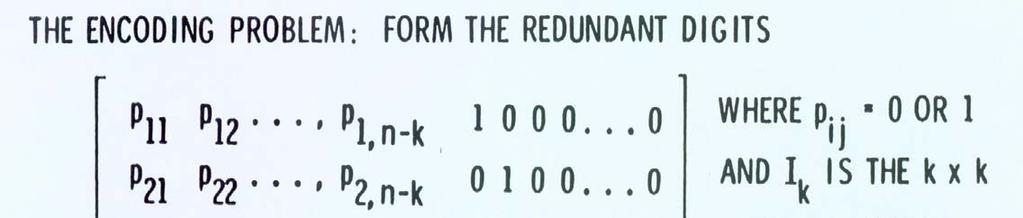
47 Linear Block Codes Encoder transforms block of k successive binary digits into longer block of n (n>k) binary digits. Called an (n,k) code. Redundancy = n-k; Code Rate = k/n; There are 2 k possible messages. There are 2 k possible code words corresponding to the messages. Code word (or code vector) is an n-tuple from the space V n of all n-tuple. Storing the 2 k code vector in a dictionary is prohibitive for large k. 47
48 Vector Spaces The set of all binary n-tuples, V n, is called a vector space over GF (2). GF: Galois Field. Two operations are defined: Addition: V + U = V1 + U1 + V2 + U V n + U n Scalar Multiplication: a V = av1 + av av n Example: Vector Space V (0101)+(1110)=(0+1, 1+1, 0+1, 1+0)=(1, 0, 1, 1) 1 (1010)=(1 1, 1 0, 1 1, 1 0)=(1, 0, 1, 0) 48
49 Subspaces A subset S of V n is a subspace if The all-zero vector is in S The sum of any two vectors in S is also in S. Example of S: V V V V = 0000 = 0101 = 1010 =
50 Reducing Encoding Complexity Key feature of linear block codes: the 2 k code vectors form a k-dimensional subspace of all n-tuples. Example: k = 3, 2 k = 8, n = 6, ( 6, 3 ) code Message Code Word A 3 - dimensiona l subspace of the vector space of all 6 - tuples. 50
51 1 2 Reducing Encoding Complexity It is possible to find a set of k linearly independent n- tuples v, v,..., v such that each n-tuple of the suspace k is a linear combination of v, v,..., v. 1 2 k Code word u = m1 v1 + m2v2 where m = 0 or 1 i i = 1,..., k m k v k 51
52 Generator Matrix v1 v11 v12 v1 n v 2 v21 v22 v 2n G = = = k n Generator Matrix v k vk1 vk2 vkn The 2 k code vectors can be described by a set of k linearly independent code vectors. Let m=[m 1, m 2,, m k ] be a message. Code word corresponding to message m is obtained by: v u = mg = [ m m m ] k 1 v v 2 k
53 Storage is greatly reduced. Generator Matrix The encoder needs to store the k rows of G instead of the 2 k code vectors of the code. For example: Let Then v G = v = and m= 2 v v1 = 1 v1+ 1 v2 + 0 v3 u = = [ 1 1 0] [ 1 1 0] v2 1 [ ] 1 [ ] 0 [ ] v = [ ] Code Vector for m= [ 110] 3


54 Systematic Code 54
55 Parity Check Matrix For each generator matrix G, there exists a parity check matrix H such that the rows of G are orthogonal to the rows of H. (u h=0) h1 h11 h12 h1 n h 2 h21 h22 h 2n H = = h ( n k) h( n k)1 h( n k)2 h( n k) n u = u, u,, u 1 2 n T uh = u1hi 1+ u2hi2 + + unhin = where i = 1, 2,, n k U is a code word generated by matrix G if and only if uh T =0 0 55
56 Parity Check Matrix and Syndrome In a systematic code with G=[P kxr I kxk ] H=[I rxr P T rxk ] u e r Received Code Error = + Vector Vector Vector Syndrome of r used for error detection and correction s = rh T Syndrome s = 0 0 If r is a code Otherwise vector 56
57 Example of Syndrome Test T H = [ In k P ] G = = H P Ik The 6-tuple is the code vector corresponding to the message T s = u H = = [ ] [ 0 0 0] Compute the syndrome for the non-code-vector T [ ] H [ 1 0 0] s = = 57
58 Weight and Distance of Binary Vectors Hamming Weight of a Vector: w(v) = Number of non-zero bits in the vector. Hamming Distance between 2 vectors: d(u,v) = Number of bits in which they differ. For example: u= v= d(u,v) = 5. d(u,v) =w(u+v) The Hamming Distance between 2 vectors is equal to the Hamming Weight of their vector sum. 58
59 Minimum Distance of a Linear Code The set of all code vectors of a linear code form a subspace of the n-tuple space. If u and v are 2 code vectors, then u+v must also be a code vector. Therefore, the distance d(u,v) between 2 code vectors equals the weight of a third code vector. d(u,v) =w(u+v)=w(w) Thus, the minimum distance of a linear code equals the minimum weight of its code vectors. A code with minimum distance d min can be shown to correct (d min -1)/2 erroneous bits and detect (d min -1) erroneous bits. 59
60 Example of Minimum Distance d min =3 60
61 Example of Error Correction and Detection Capability u v d min ( u, v) = 7 t max = d min 2 1 : Error Correcting Strength m max = d min 1 : Error Detecting Strength 61
62 Convolutional Code Structure 1 2 K k bits 1 2 k 1 2 k 1 2 k 1 2 n-1 n Output 62
63 Convolutional codes Convoltuional Code k = number of bits shifted into the encoder at one time k=1 is usually used!! n = number of encoder output bits corresponding to the k information bits r = k/n = code rate K = constraint length, encoder memory Each encoded bit is a function of the present input bits and their past ones. 63
64 Generator Sequence u r 0 r 1 r 2 v (1) (1) (1) (1) g0 = 1, g1 = 0, g 2 = 1, and g3 = 1. Generator Sequence: g (1) =( ) u r 0 r 1 r 2 r 3 v (2) (2) (2) (2) (2) g0 = 1, g1 = 1, g 2 = 1, g3 = 0, and g 4 = 1. Generator Sequence: g (2) =( ) 64
65 Convolutional Codes An Example (rate=1/2 with K=2) x 1 x 2 G 1 (x)=1+x 2 G 2 (x)=1+x 1 +x 2 0(00) Present Next Output 0(11) 00 1(11) (01) (00) 0(10) 1(10) (01) State Diagram 65
66 Trellis Diagram Representation 0(00) (00) 00 0(00) 00 0(00) 00 0(00) 0(00) 0(00) (11) 1(11) 1(11) 1(11) 1(11) 0(11) 0(11) 0(11) 0(11) 0(11) 1(00) 1(00) 1(00) 0(01) 0(01) 0(01) 0(01) 0(01) 1(10) 1(10) 1(10) 1(10) 0(10) 0(10) 0(10) 0(10) 1(01) 1(01) 1(01) Trellis termination: K tail bits with value 0 are usually added to the end of the code.
67 Encoding Process Input: Output: (00) 00 0(00) 00 0(00) 00 0(00) 00 0(00) 00 0(00) 00 0(00) 1(11) 1(11) 1(11) 1(11) 1(11) (11) 1(00) 01 0(11) 1(00) 01 0(11) 1(00) 01 0(11) 01 0(11) 0(01) 0(01) 10 1(10) 0(01) 0(01) 0(01) (10) 1(10) 1(10) 0(10) 11 1(01) 0(10) 11 1(01) 0(10) 11 1(01) 0(10) 11 67
68 Viterbi Decoding Algorithm Maximum Likelihood (ML) decoding rule received sequence r ML min(d,r)!! detected sequence d Viterbi Decoding Algorithm An efficient search algorithm Performing ML decoding rule. Reducing the computational complexity. 68
69 Basic concept Viterbi Decoding Algorithm Generate the code trellis at the decoder The decoder penetrates through the code trellis level by level in search for the transmitted code sequence At each level of the trellis, the decoder computes and compares the metrics of all the partial paths entering a node The decoder stores the partial path with the larger metric and eliminates all the other partial paths. The stored partial path is called the survivor. 69
70 Viterbi Decoding Process Output: Receive: (00) 0(00) 0(00) 0(00) 0(00) 0(00) 0(00) (11) 2 1(11) 1(11) 1(11) 1(11) (11) 1(00) 01 0(11) 1(00) 01 0(11) 1(00) 01 0(11) 01 0(11) 0(01) 0(01) 0(01) 0(01) 0(01) (10) (10) 1(10) 0(10) 1(10) 0(10) 1(10) 0(10) 11 1(01) 11 1(01) 11 1(01) 11 70
71 Viterbi Decoding Process Output: Receive: (00) 0(00) 0(00) 0(00) 0(00) 0(00) 0(00) (11) 2 1(11) 4 1(11) 1(11) 1(11) (11) 1(00) 01 0(11) 1(00) 01 0(11) 1(00) 01 0(11) 01 0(11) 0(01) 0(01) 0(01) 0(01) 0(01) (10) (10) 1(10) 0(10) 1(10) 0(10) 1(10) 0(10) (01) 11 1(01) (01) 11
72 Viterbi Decoding Process Output: Receive: (00) 0(00) 0(00) 0(00) 0(00) 0(00) 0(00) (11) 2 1(11) 4 1(11) 3 1(11) 1(11) (01) 1(10) (11) 1(00) 0(01) (10) 1(10) 2 1 0(11) 1(00) 0(01) 0(10) 1(10) 0(11) 1(00) 0(01) 0(10) 1(10) 0(11) 0(01) 0(11) 0(10) (01) (01) (01) 11
73 Viterbi Decoding Process Output: Receive: (00) 0(00) 0(00) 0(00) 0(00) 0(00) 0(00) (11) 2 1(11) 4 1(11) 3 1(11) 3 1(11) (01) 1(10) (11) 1(00) 0(01) (10) 1(10) 2 1 0(11) 1(00) 0(01) 0(10) 1(10) 2 3 0(11) 1(00) 0(01) 0(10) 1(10) 0(11) 0(01) 0(11) 0(10) (01) (01) (01) 11
74 Viterbi Decoding Process Output: Receive: (00) 0(00) 0(00) 0(00) 0(00) 0(00) 0(00) (11) 2 1(11) 4 1(11) 3 1(11) 3 1(11) (01) 1(10) (11) 1(00) 0(01) (10) 1(10) 2 1 0(11) 1(00) 0(01) 0(10) 1(10) 2 3 0(11) 1(00) 0(01) 0(10) 1(10) 3 3 0(11) 0(01) 0(11) 0(10) (01) (01) (01) 11 1
75 Viterbi Decoding Process Output: Receive: (00) 0(00) 0(00) 0(00) 0(00) 0(00) 0(00) (11) 2 1(11) 4 1(11) 3 1(11) 3 1(11) (01) 1(10) (11) 1(00) 0(01) (10) 1(10) 2 1 0(11) 1(00) 0(01) 0(10) 1(10) 2 3 0(11) 1(00) 0(01) 0(10) 1(10) 3 3 0(11) 0(01) 2 0(11) 0(10) (01) (01) (01) 11 1
76 Viterbi Decoding Process Output: Receive: (00) 0(00) 0(00) 0(00) 0(00) 0(00) 0(00) (11) 2 1(11) 4 1(11) 3 1(11) 3 1(11) (01) 1(10) (11) 1(00) 0(01) (10) 1(10) 2 1 0(11) 1(00) 0(01) 0(10) 1(10) 2 3 0(11) 1(00) 0(01) 0(10) 1(10) 3 3 0(11) 0(01) 2 0(11) 0(10) (01) (01) (01) 11 1
77 Viterbi Decoding Process Decision: Receive: (00) 0(00) 0(00) 0(00) 0(00) 0(00) 0(00) (11) 2 1(11) 4 1(11) 3 1(11) 3 1(11) (01) 1(10) (11) 1(00) 0(01) (10) 1(10) 2 1 0(11) 1(00) 0(01) 0(10) 1(10) 2 3 0(11) 1(00) 0(01) 0(10) 1(10) 3 3 0(11) 0(01) 2 0(11) 0(10) (01) (01) (01) 11 1


78 Channel Coding in GSM 78


79 Channel Coding in IS-54/136 79
80 Turbo Codes Basic Concepts Turbo coding uses parallel concatenation of two recursive systematic convolutional codes joined through an interleaver. Information bits are encoded block by block. Turbo codes uses iterative decoding techniques. Soft-output decoder is necessary for iterative decoding. Turbo codes can approach to Shannon limit. 80
81 Turbo Codes Encoder An Example X(t) Y(t) X(t) Interleaver Y (t) X'(t) When the switch is placed on the low position, the tail bits are feedback and the trellis will be terminated. 81
82 Turbo Codes Encoding Example A systematic convolutional encoder with memory 2 The dotted line is for termination code Test sequence: 1011 X 0 X D D 82
83 Turbo Codes Encoding Example X 0 =1 X 1 =
84 Turbo Codes Encoding Example X 0 =0 X 1 =
85 Turbo Codes Encoding Example X 0 =1 X 1 =
86 Turbo Codes Encoding Example X 0 =1 X 1 =
87 Turbo Codes Encoding Example 1 1 X 0 =0 X 1 =
88 Turbo Codes Encoding Example 0 1 X 0 =1 X 1 =
89 Turbo Codes Encoding Example 0 0 X 0 =0 X 1 =
90 Turbo Codes Encoding Example X D D X 1 Interleaver (X 0 ) D D X 2 Output sequence: X 0, X 1, X 2, X 0, X 1, X 2, X 0, X 1, X 2,... 90
91 Turbo Codes Encoding Example The second encoder input is the interleaved data
92 CRC in WCDMA g CRC24 (D) = D 24 + D 23 + D 6 + D 5 + D + 1; g CRC16 (D) = D 16 + D 12 + D 5 + 1; g CRC12 (D) = D 12 + D 11 + D 3 + D 2 + D + 1; g CRC8 (D) = D 8 + D 7 + D 4 + D 3 + D
93 Channel Coding Adopted in WCDMA Type of TrCH BCH Coding scheme Coding rate PCH Convolutional 1/2 RACH coding CPCH, DCH, DSCH, FACH 1/3, 1/2 Turbo coding 1/3 No coding 93
94 Convolutional Coding in WCDMA Input D D D D D D D D (a) Rate 1/2 convolutional coder Output 0 G 0 = 561 (octal) Output 1 G 1 = 753 (octal) Input D D D D D D D D (b) Rate 1/3 convolutional coder Output 0 G 0 = 557 (octal) Output 1 G 1 = 663 (octal) Output 2 G 2 = 711 (octal) 94
95 Turbo Coder in WCDMA xk 1st constituent encoder zk Input xk D D D Input Turbo code internal interleaver Output 2nd constituent encoder z k Output x k D D D x k 95
96 Interleaving
97 Typical Digital Communications System From Other Sources Information Bits Source Bits Channel Bits Format Digital Input m i Digital Output mˆ i Source Encoding Encryption Channel Encoding Bit Stream Interleaving Multiplexing Modulation (t) s i Synchronization ˆ ( t) s i Frequency Spreading Digital Waveform Multiple Access TX RF PA C H A N N E L Format Source Decoding Decryption Channel Decoding Deinterleaving Demultiplexing Demodulation Frequency Despreading Multiple Access RX RF IF Information Sink Source Bits Optional Essential Channel Bits To Other Destinations 97


98 Bursty Error in Fading Channel 98
99 Interleaving Mechanism (1/2) x x Write Clock Bit Interleaver j x n-bit Shift registers y y Read Clock Bit Stream before entering bit interleaver: x=(a 11 a 12 a 1n a 21 a 22 a 2n a j1 a j2 a jn ) 99
100 Interleaving Mechanism (2/2) y Conceptually, the WRITE clock places the bit stream x by the row while the REA clock takes the bit stream y by the column: a a... a j1 a a a... j Bit stream at the output of the bit interleaver: = ( a a a a a... a... a a... a ) j j 2 1n 2n a a a 1n 2n... jn jn 100
101 Burst Error Protection with Interleaver 101
102 Modulation
103 Typical Digital Communications System From Other Sources Information Bits Source Bits Channel Bits Format Digital Input m i Digital Output mˆ i Source Encoding Encryption Channel Encoding Bit Stream Interleaving Multiplexing Modulation (t) s i Synchronization ˆ ( t) s i Frequency Spreading Digital Waveform Multiple Access TX RF PA C H A N N E L Format Source Decoding Decryption Channel Decoding Deinterleaving Demultiplexing Demodulation Frequency Despreading Multiple Access RX RF IF Information Sink Source Bits Optional Essential Channel Bits To Other Destinations 103
104 Modulation Digital Modulation: digital symbols are transformed into waveforms that are compatible with the characteristics of the channel. In baseband modulation, these waveforms are pulses. In bandpass modulation, the desired information signal modulates a sinusoid called a carrier. For radio transmission, the carrier is converted in an electromagnetic (EM) wave. Why modulation? Antenna size should be comparable with wave length baseband transmission is not possible. Modulation may be used to separate the different signals using a single channel. 104


105 PCM Waveform Representations 105
106 PCM Waveform Representations PCM waveform is also called line codes. Digital baseband signals often use line codes to provide particular spectral characteristics of a pulse train. NRZ-L. NRZ-M. NRZ-S. Unipolar-RZ. Polar-RZ. Bi-φ-L. Bi-φ-M. Bi-φ-S. Dicode-NRZ. Dicode-RZ. Delay Mode. 4B3T. Multi-level. etc. 106
107 PCM Waveform : NRZ-L E 0 -E NRZ Level (or NRZ Change) One is represented by one level. Zero is represented by the other level. 107
108 PCM Waveform : NRZ-M E 0 -E NRZ Mark (Differential Encoding) One is represented by a change in level. Zero is represented by a no change in level. 108
109 PCM Waveform : NRZ-S E 0 -E NRZ Space (Differential Encoding) One is represented by a no change in level. Zero is represented by a change in level. 109
110 PCM Waveform : Unipolar-RZ E 0 -E Unipolar - RZ One is represented by a half-bit width pulse. Zero is represented by a no pulse condition. 110
111 PCM Waveform : Polar-RZ E 0 -E Polar - RZ One and Zero are represented by opposite level polar pulses that are one half-bit in width. 111
112 PCM Waveform : Bi-φ-L E 0 -E Bi-φ-L (Biphase Level or Split Phase Manchester o ) One is represented by a 10. Zero is represented by a
113 PCM Waveform : Bi-φ-M E 0 -E Bi-φ-M ( Biphase Mark or Manchester 1) A transition occurs at the beginning of every bit period. One is represented by a second transition one half bit period later. Zero is represented by no second transition. 113
114 PCM Waveform : Bi-φ-S E 0 -E Bi-φ-S ( Biphase Space) A transition occurs at the beginning of every bit period. One is represented by no second transition. Zero is represented by a second transition one-half bit period later. 114
115 PCM Waveform : Dicode - NRZ E 0 -E Dicode Non-Return-to-Zero A One to Zero or Zero to One changes polarity. Otherwise, a Zero is sent. 115
116 PCM Waveform : Dicode - RZ E 0 -E Dicode Return-to-Zero A One to Zero or Zero to One transition produces a half duration polarity change. Otherwise, a Zero is sent. 116
117 PCM Waveform : Delay Mode +E E Dicode Non-Return-to-Zero A One is represented by a transition at the midpoint of the bit interval. A Zero is represented by a no transition unless it is followed by another zero. In this case, a transition is placed at the end of bit period of the first zero. 117
118 PCM Waveform : 4B3T O-- 118
119 PCM Waveform : 4B3T Ternary words in the middle column are balanced in their DC content. Code words from the first and third columns are selected alternately to maintain DC balance. If more positive pulses than negative pulses have been transmitted, column 1 is selected. Notice that the all-zeros code word is not used. 119
120 PCM Waveform : Multilevel Transmission Multilevel transmission with 3 bits per signal interval. 120
121 Criteria for Selecting PCM Waveform DC component: eliminating the dc energy from the signal s power spectrum. Self-Clocking: Symbol or bit synchronization is required for any digital communication system. Error detection: some schemes provide error detection without introducing additional error-detection bits. Bandwidth compression: some schemes increase bandwidth utilization by allowing a reduction in required bandwidth for a given data rate. Noise immunity. Cost and complexity. 121

122 Spectral Densities of Various PCM Waveforms 122
123 Linear Modulation Techniques Digital modulation techniques may be broadly classified as linear and nonlinear. In linear modulation techniques, the amplitude of the transmitted signal, s(t), varies linearly with the modulating digital signal, m(t). Linear modulation techniques are bandwidth efficient, though they must be transmitted using linear RF amplifiers which have poor power efficiency. Using power efficient nonlinear amplifiers leads to the regeneration of filtered sidelobes which can cause severe adjacent channel interference, and results in the loss of all the spectral efficiency gained by linear modulation. Clever ways have been developed to get around these difficulties: QPSK, OQPSK, π/4-qpsk. 123
124 Digital Modulations Basic digital modulated signal: v(t) = A(t) cos (ωt + θ) Where A(t) = Amplitude; ω = Frequency; θ = Phase; 124


125 Basic Digital Modulations 125
 j = 1,2,, 16 Gray Coding.")
126 Extended Modulated Signals M-FSK Example: 16-FSK Every 4 bits is encoded as: A cos( ω jt) j = 1,2,, 16 Gray Coding. 126

 j = 1,2,,16 j Dotted")
127 Gray Coding. Extended Modulated Signals M-PSK Example: 16-PSK Every 4 bits is encoded as: A sin( ω t+ θ ) j = 1,2,,16 j Dotted lines are decision boundaries. 127

128 Extended Modulated Signals 16-QAM Every 4 bits is represented by one point in the signal constellation. Every point has its unique amplitude and phase. 128
129 Binary Phase Shift Keying (BPSK) In BPSK, the phase of a constant amplitude carrier signal is switched between two values according to the two possible signals m 1 and m 2 corresponding to binary 1 and 0. Normally, the two phases are separated by 180 o. 2Eb sbpsk () t = m() t cos( 2 π fct+ θc ) 0 t Tb T = b () ( π ) { g t j f t } Re exp 2 BPSK 2Eb jθ sinπ ft c b gbpsk () t = m() t e P ()( f ) = 2E gbpsk t b Tb π ftb 2 2 E sinπ ( f fc) T b sinπ b ( f fc) T b PBPSK ( f ) = + 2 π ( f fc) T b π ( f fc) T b 129 c 2
130 Power Spectral Density (PSD) of a BPSK Signal. 130
131 BPSK Receiver BPSK uses coherent or synchronous demodulation, which requires that information about the phase and frequency of the carrier be available at the receiver. If a low level pilot carrier signal is transmitted along with the BPSK signal, then the carrier phase and frequency may be recovered at the receiver using a phase locked loop (PLL). If no pilot carrier is transmitted, a Costas loop or squaring loop may be used to synthesize the carrier phase and frequency from the received BPSK signal. 131
132 BPSK Receiver with Carrier Recovery Circuits 132
133 Operations of BPSK Receiver with Carrier Recovery Circuits The received signal is squared to generate a DC signal and an amplitude varying sinusoid at twice the carrier frequency. The DC signal is filtered out using a bandpass filter with center frequency tuned to 2f c. A frequency divider is used to recreate the waveform cos(2πf c t+θ). The output of the multiplier is applied to an integrate and dump circuit which forms the low pass filter segment of a BPSK detector. If the transmitter and receiver pulse shapes are matched, then the detection will be optimum. A bit synchronizer is used to facilitate sampling of the integrator output precisely at the end of each bit period. 133
134 Differential Phase Shift Keying (DPSK) Differential PSK is a noncoherent form of phase shift keying which avoids the need for a coherent reference signal at the receiver. dk = mk dk 1 134
135 Block Diagram of DPSK Receiver 135
136 Quadrature Phase Shift Keying (QPSK) 136
137 Spectrum of QPSK Signals sinπ ( f fc) T s sinπ ( f fc) T s PQPSK ( f ) = E b + π ( f fc) T π ( f fc) T
138 Block Diagram of a QPSK Transmitter 138
139 Block Diagram of a QPSK Receiver 139
140 Offset QPSK (OQPSK) For QPSK, the occasional phase shift of πradians can cause the signal envelope to pass through zero for just an instant. The amplification of the zero-crossings brings back the filtered sidelobes since the fidelity of the signal at small voltage levels is lost in transmission. To prevent the regeneration of sidelobes and spectral widening, it is imperative that QPSK signals that use pulse shaping be amplified only using linear amplifiers, which are less efficient. A modified form of QPSK, called offset QPSK (OQPSK) or staggered QPSK is less susceptible to these deleterious effects and supports more efficient amplification. OQPSK ensures there are fewer baseband signal transitions. Spectrum of an OQPSK signal is identical to that of QPSK. 140
141 Offset QPSK (OQPSK) The time offset waveforms that are applied to the in-phase and quadrature arms of an OQPSK modulator. Notice that a halfsymbol offset is used. 141
142 π/4-dqpsk 142
143 Generic π/4-dqpsk Transmitter 143
144 π/4-dqpsk Baseband Differential Detector 144
145 Detection of Binary Signals in Gaussian Noise 145
146 Digital Demodulation Techniques Coherent detection: Exact replicas of the possible arriving signals are available at the receiver. This means that the receiver has exact knowledge of the carrier wave s phase reference, in which case we say the receiver is phase-locked to the transmitter. Coherent detection is performed by crosscorrelating the received signal with each one of the replicas, and then making a decision based on comparisons with preselected thresholds. Non-coherent detection: Knowledge of the carrier wave s phase is not required. The complexity of the receiver is thereby reduced but at the expense of an inferior error performance, compared to a coherent system. 146
147 Correlation Demodulator 147
148 Matched Filter Demodulator 148


149 Inter-Symbol Interference (ISI) 149
150 Inter Symbol Interference (ISI) Inter-Symbol Interference (ISI) arises because of imperfections in the overall frequency response of the system. When a short pulse of duration T b seconds is transmitted through a band-limited system, the frequency components constituting the input pulse are differentially attenuated and differentially delayed by the system. Consequently, the pulse appearing at the output of the system is dispersed over an interval longer than T b seconds, thereby resulting in intersymbol interference. Even in the absence of noise, imperfect filtering and system bandwidth constraints lead to ISI. 150
151 Nyquist Channels for Zero ISI The Nyquist channel is not physically realizable since it dictates a rectangular bandwidth characteristic and an infinite time delay. Detection process would be very sensitive to small timing errors. Solution: Raised Cosine Filter. 151
152 152 Raised Cosine Filter Factor: Roll- Off Excess Bandwidth: 2 1 for for 2 2 for 0 ) 2 4 ( cos 1 ) ( W W W r W W T W W f W f W W W W f W W W W f f H = = > < < < + = π
153 Raised Cosine Filter Characteristics 153
154 Raised Cosine Filter Characteristics 154
155 Equalization In practical systems, the frequency response of the channel is not known to allow for a receiver design that will compensate for the ISI. The filter for handling ISI at the receiver contains various parameters that are adjusted with the channel characteristics. The process of correcting the channel-induced distortion is called equalization. 155


156 Equalization 156
157 Introduction to RAKE Receiver Multiple versions of the transmitted signal are seen at the receiver through the propagation channels. Very low correlation between successive chips is in CDMA spreading codes. If these multi-path components are delayed in time by more than a chip duration, they appear like uncorrelated noise at a CDMA receiver. Equalization is NOT necessary Combine Coherently 157
158 Introduction to RAKE Receiver To utilize the advantages of diversity techniques, channel parameters are necessary to be estimated. Arrival time of each path, Amplitude, and Phase. Maximal Ratio Combiner (MRC): The combiner that achieves the best performance is one in which each output is multiplied by the corresponding complexvalued (conjugate) channel gain. The effect of this multiplication is to compensate for the phase shift in the channel and to weight the signal by a factor that is proportional to the signal strength. 158
159 Maximum Ratio Combining (MRC) MRC: G i =A i e -jθ i Coherent Combining G 1 G 2 G L Channel Estimation Best Performance Receiver 159
160 Maximum Ratio Combining (MRC) Received Envelope: r = G r Total Noise Power: SNR: Since SNR L 2 rl = = 2 σ 2 n L l l l= 1 σ L n = Gl σ n, l l= 1 2 l= 1 L l= σ n, l L 2 L rl Gl r l Glσ n, l l= 1 l= 1 σ nl, L L G l G l r = l 2
161 161 Maximum Ratio Combining (MRC) *, *, 1 1 2, 2 1 2, , 2, 1 1 2, 2, 2 1 SNRs from all Sum of Output SNR With equality hold : Inequality: Chebychev's l l l n l l n l L l l L l l n l L l l n l L l L l l n l l n l L L l L l l n l l n l L l l l r G r k G SNR r G r G SNR r G r G = = = = = = = = = = = = σ σ σ σ σ σ σ σ
162 Example of RAKE Receiver Structure 162
163 Advantages of RAKE Receiver Consider a receiver with only one finger: Once the output of a single correlator is corrupted by fading, large bit error is expected. Consider a RAKE receiver If the output of a single correlator is corrupted by fading, the others may NOT be. Diversity is provided by combining the outputs Overcome fading Improve CDMA reception 163
Introduction to Digital Communications System
 Wireless Information Transmission System Lab. Introduction to Digital Communications System Institute of Communications Engineering National Sun Yat-sen University Recommended Books Digital Communications
Department of Electronics and Communication Engineering 1
 UNIT I SAMPLING AND QUANTIZATION Pulse Modulation 1. Explain in detail the generation of PWM and PPM signals (16) (M/J 2011) 2. Explain in detail the concept of PWM and PAM (16) (N/D 2012) 3. What is the
QUESTION BANK EC 1351 DIGITAL COMMUNICATION YEAR / SEM : III / VI UNIT I- PULSE MODULATION PART-A (2 Marks) 1. What is the purpose of sample and hold
 1. What is the purpose of sample and hold") QUESTION BANK EC 1351 DIGITAL COMMUNICATION YEAR / SEM : III / VI UNIT I- PULSE MODULATION PART-A (2 Marks) 1. What is the purpose of sample and hold circuit 2. What is the difference between natural sampling
QUESTION BANK EC 1351 DIGITAL COMMUNICATION YEAR / SEM : III / VI UNIT I- PULSE MODULATION PART-A (2 Marks) 1. What is the purpose of sample and hold circuit 2. What is the difference between natural sampling
Fundamentals of Digital Communication
 Fundamentals of Digital Communication Network Infrastructures A.A. 2017/18 Digital communication system Analog Digital Input Signal Analog/ Digital Low Pass Filter Sampler Quantizer Source Encoder Channel
Physical Layer: Modulation, FEC. Wireless Networks: Guevara Noubir. S2001, COM3525 Wireless Networks Lecture 3, 1
 Wireless Networks: Physical Layer: Modulation, FEC Guevara Noubir Noubir@ccsneuedu S, COM355 Wireless Networks Lecture 3, Lecture focus Modulation techniques Bit Error Rate Reducing the BER Forward Error
UNIT I Source Coding Systems
 SIDDHARTH GROUP OF INSTITUTIONS: PUTTUR Siddharth Nagar, Narayanavanam Road 517583 QUESTION BANK (DESCRIPTIVE) Subject with Code: DC (16EC421) Year & Sem: III-B. Tech & II-Sem Course & Branch: B. Tech
QUESTION BANK SUBJECT: DIGITAL COMMUNICATION (15EC61)
") QUESTION BANK SUBJECT: DIGITAL COMMUNICATION (15EC61) Module 1 1. Explain Digital communication system with a neat block diagram. 2. What are the differences between digital and analog communication systems?
QUESTION BANK SUBJECT: DIGITAL COMMUNICATION (15EC61) Module 1 1. Explain Digital communication system with a neat block diagram. 2. What are the differences between digital and analog communication systems?
Syllabus. osmania university UNIT - I UNIT - II UNIT - III CHAPTER - 1 : INTRODUCTION TO DIGITAL COMMUNICATION CHAPTER - 3 : INFORMATION THEORY
 i Syllabus osmania university UNIT - I CHAPTER - 1 : INTRODUCTION TO Elements of Digital Communication System, Comparison of Digital and Analog Communication Systems. CHAPTER - 2 : DIGITAL TRANSMISSION
Downloaded from 1
 VII SEMESTER FINAL EXAMINATION-2004 Attempt ALL questions. Q. [1] How does Digital communication System differ from Analog systems? Draw functional block diagram of DCS and explain the significance of
DIGITAL COMMUNICATIONS SYSTEMS. MSc in Electronic Technologies and Communications
 DIGITAL COMMUNICATIONS SYSTEMS MSc in Electronic Technologies and Communications Bandpass binary signalling The common techniques of bandpass binary signalling are: - On-off keying (OOK), also known as
EXPERIMENT WISE VIVA QUESTIONS
 EXPERIMENT WISE VIVA QUESTIONS Pulse Code Modulation: 1. Draw the block diagram of basic digital communication system. How it is different from analog communication system. 2. What are the advantages of
EEE 309 Communication Theory
 EEE 309 Communication Theory Semester: January 2017 Dr. Md. Farhad Hossain Associate Professor Department of EEE, BUET Email: mfarhadhossain@eee.buet.ac.bd Office: ECE 331, ECE Building Types of Modulation
EC6501 Digital Communication
 EC6501 Digital Communication UNIT -1 DIGITAL COMMUNICATION SYSTEMS Digital Communication system 1) Write the advantages and disadvantages of digital communication. [A/M 11] The advantages of digital communication
UNIT TEST I Digital Communication
 Time: 1 Hour Class: T.E. I & II Max. Marks: 30 Q.1) (a) A compact disc (CD) records audio signals digitally by using PCM. Assume the audio signal B.W. to be 15 khz. (I) Find Nyquist rate. (II) If the Nyquist
Digital to Digital Encoding
 MODULATION AND ENCODING Data must be transformed into signals to send them from one place to another Conversion Schemes Digital-to-Digital Analog-to-Digital Digital-to-Analog Analog-to-Analog Digital to
Contents Preview and Introduction Waveform Encoding
 Contents 1 Preview and Introduction... 1 1.1 Process of Communication..... 1 1.2 General Definition of Signal..... 3 1.3 Time-Value Definition of Signals Analog and Digital..... 6 1.3.1 Continuous Time
DIGITAL COMMINICATIONS
 Code No: R346 R Set No: III B.Tech. I Semester Regular and Supplementary Examinations, December - 23 DIGITAL COMMINICATIONS (Electronics and Communication Engineering) Time: 3 Hours Max Marks: 75 Answer
EEE 309 Communication Theory
 EEE 309 Communication Theory Semester: January 2016 Dr. Md. Farhad Hossain Associate Professor Department of EEE, BUET Email: mfarhadhossain@eee.buet.ac.bd Office: ECE 331, ECE Building Part 05 Pulse Code
QUESTION BANK. Staff In-Charge: M.MAHARAJA, AP / ECE
 FATIMA MICHAEL COLLEGE OF ENGINEERING & TECHNOLOGY Senkottai Village, Madurai Sivagangai Main Road, Madurai -625 020 An ISO 9001:2008 Certified Institution QUESTION BANK Sub. Code : EC 2301 Class : III
About Homework. The rest parts of the course: focus on popular standards like GSM, WCDMA, etc.
 About Homework The rest parts of the course: focus on popular standards like GSM, WCDMA, etc. Good news: No complicated mathematics and calculations! Concepts: Understanding and remember! Homework: review
CHAPTER 3 Syllabus (2006 scheme syllabus) Differential pulse code modulation DPCM transmitter
 Differential pulse code modulation DPCM transmitter") CHAPTER 3 Syllabus 1) DPCM 2) DM 3) Base band shaping for data tranmission 4) Discrete PAM signals 5) Power spectra of discrete PAM signal. 6) Applications (2006 scheme syllabus) Differential pulse code
CHAPTER 3 Syllabus 1) DPCM 2) DM 3) Base band shaping for data tranmission 4) Discrete PAM signals 5) Power spectra of discrete PAM signal. 6) Applications (2006 scheme syllabus) Differential pulse code
Digital Modulation Schemes
 Digital Modulation Schemes 1. In binary data transmission DPSK is preferred to PSK because (a) a coherent carrier is not required to be generated at the receiver (b) for a given energy per bit, the probability
LATHA MATHAVAN ENGINEERING COLLEGE Alagarkovil, Madurai
 UNIT I - SAMPLING & QUANTIZATION PART A 1. What is aliasing? (EC6501 June 2016) 2. What is Companding? Sketch the input-output characteristics of a compressor and an expander. (EC6501 June 2016) 3. An
Communications I (ELCN 306)
") Communications I (ELCN 306) c Samy S. Soliman Electronics and Electrical Communications Engineering Department Cairo University, Egypt Email: samy.soliman@cu.edu.eg Website: http://scholar.cu.edu.eg/samysoliman
Communications I (ELCN 306) c Samy S. Soliman Electronics and Electrical Communications Engineering Department Cairo University, Egypt Email: samy.soliman@cu.edu.eg Website: http://scholar.cu.edu.eg/samysoliman
QUESTION BANK (VI SEM ECE) (DIGITAL COMMUNICATION)
 (DIGITAL COMMUNICATION)") QUESTION BANK (VI SEM ECE) (DIGITAL COMMUNICATION) UNIT-I: PCM & Delta modulation system Q.1 Explain the difference between cross talk & intersymbol interference. Q.2 What is Quantization error? How does
QUESTION BANK (VI SEM ECE) (DIGITAL COMMUNICATION) UNIT-I: PCM & Delta modulation system Q.1 Explain the difference between cross talk & intersymbol interference. Q.2 What is Quantization error? How does
PRINCIPLES OF COMMUNICATIONS
 PRINCIPLES OF COMMUNICATIONS Systems, Modulation, and Noise SIXTH EDITION INTERNATIONAL STUDENT VERSION RODGER E. ZIEMER University of Colorado at Colorado Springs WILLIAM H. TRANTER Virginia Polytechnic
Detection and Estimation of Signals in Noise. Dr. Robert Schober Department of Electrical and Computer Engineering University of British Columbia
 Detection and Estimation of Signals in Noise Dr. Robert Schober Department of Electrical and Computer Engineering University of British Columbia Vancouver, August 24, 2010 2 Contents 1 Basic Elements
Wireless Communications
 Wireless Communications Lecture 5: Coding / Decoding and Modulation / Demodulation Module Representive: Prof. Dr.-Ing. Hans D. Schotten schotten@eit.uni-kl.de Lecturer: Dr.-Ing. Bin Han binhan@eit.uni-kl.de
Digital Communication (650533) CH 3 Pulse Modulation
 CH 3 Pulse Modulation") Philadelphia University/Faculty of Engineering Communication and Electronics Engineering Digital Communication (650533) CH 3 Pulse Modulation Instructor: Eng. Nada Khatib Website: http://www.philadelphia.edu.jo/academics/nkhatib/
Philadelphia University/Faculty of Engineering Communication and Electronics Engineering Digital Communication (650533) CH 3 Pulse Modulation Instructor: Eng. Nada Khatib Website: http://www.philadelphia.edu.jo/academics/nkhatib/
techniques are means of reducing the bandwidth needed to represent the human voice. In mobile
 8 2. LITERATURE SURVEY The available radio spectrum for the wireless radio communication is very limited hence to accommodate maximum number of users the speech is compressed. The speech compression techniques
COMMUNICATION SYSTEMS
 COMMUNICATION SYSTEMS 4TH EDITION Simon Hayhin McMaster University JOHN WILEY & SONS, INC. Ш.! [ BACKGROUND AND PREVIEW 1. The Communication Process 1 2. Primary Communication Resources 3 3. Sources of
 DEPARTMENT OF COMPUTER GCE@Bodi_ SCIENCE GCE@Bodi_ AND ENIGNEERING GCE@Bodi_ GCE@Bodi_ GCE@Bodi_ Analog and Digital Communication GCE@Bodi_ DEPARTMENT OF CsE Subject Name: Analog and Digital Communication
Problem Sheet 1 Probability, random processes, and noise
 Problem Sheet 1 Probability, random processes, and noise 1. If F X (x) is the distribution function of a random variable X and x 1 x 2, show that F X (x 1 ) F X (x 2 ). 2. Use the definition of the cumulative
KINGS COLLEGE OF ENGINEERING DEPARTMENT OF ELECTRONICS AND COMMUNICATION ENGINEERING QUESTION BANK. Subject Name: Digital Communication Techniques
 KINGS COLLEGE OF ENGINEERING DEPARTMENT OF ELECTRONICS AND COMMUNICATION ENGINEERING QUESTION BANK Subject Code: EC1351 Year/Sem: III/IV Subject Name: Digital Communication Techniques UNIT I PULSE MODULATION
CHAPTER 2. Instructor: Mr. Abhijit Parmar Course: Mobile Computing and Wireless Communication ( )
") CHAPTER 2 Instructor: Mr. Abhijit Parmar Course: Mobile Computing and Wireless Communication (2170710) Syllabus Chapter-2.3 Modulation Techniques Reasons for Choosing Encoding Techniques Digital data,
CHAPTER 2 Instructor: Mr. Abhijit Parmar Course: Mobile Computing and Wireless Communication (2170710) Syllabus Chapter-2.3 Modulation Techniques Reasons for Choosing Encoding Techniques Digital data,
END-OF-YEAR EXAMINATIONS ELEC321 Communication Systems (D2) Tuesday, 22 November 2005, 9:20 a.m. Three hours plus 10 minutes reading time.
 Tuesday, 22 November 2005, 9:20 a.m. Three hours plus 10 minutes reading time.") END-OF-YEAR EXAMINATIONS 2005 Unit: Day and Time: Time Allowed: ELEC321 Communication Systems (D2) Tuesday, 22 November 2005, 9:20 a.m. Three hours plus 10 minutes reading time. Total Number of Questions:
END-OF-YEAR EXAMINATIONS 2005 Unit: Day and Time: Time Allowed: ELEC321 Communication Systems (D2) Tuesday, 22 November 2005, 9:20 a.m. Three hours plus 10 minutes reading time. Total Number of Questions:
DIGITAL COMMUNICATION
 DIGITAL COMMUNICATION TRAINING LAB Digital communication has emerged to augment or replace the conventional analog systems, which had been used widely a few decades back. Digital communication has demonstrated
Digital modulation techniques
 Outline Introduction Signal, random variable, random process and spectra Analog modulation Analog to digital conversion Digital transmission through baseband channels Signal space representation Optimal
Lecture 3 Concepts for the Data Communications and Computer Interconnection
 Lecture 3 Concepts for the Data Communications and Computer Interconnection Aim: overview of existing methods and techniques Terms used: -Data entities conveying meaning (of information) -Signals data
Objectives. Presentation Outline. Digital Modulation Revision
 Digital Modulation Revision Professor Richard Harris Objectives To identify the key points from the lecture material presented in the Digital Modulation section of this paper. What is in the examination
TSTE17 System Design, CDIO. General project hints. Behavioral Model. General project hints, cont. Lecture 5. Required documents Modulation, cont.
 TSTE17 System Design, CDIO Lecture 5 1 General project hints 2 Project hints and deadline suggestions Required documents Modulation, cont. Requirement specification Channel coding Design specification
Year : TYEJ Sub: Digital Communication (17535) Assignment No. 1. Introduction of Digital Communication. Question Exam Marks
 Assignment No. 1. Introduction of Digital Communication. Question Exam Marks") Assignment 1 Introduction of Digital Communication Sr. Question Exam Marks 1 Draw the block diagram of the basic digital communication system. State the function of each block in detail. W 2015 6 2 State
Assignment 1 Introduction of Digital Communication Sr. Question Exam Marks 1 Draw the block diagram of the basic digital communication system. State the function of each block in detail. W 2015 6 2 State
SCHEME OF COURSE WORK. Course Code : 13EC1114 L T P C : ELECTRONICS AND COMMUNICATION ENGINEERING
 SCHEME OF COURSE WORK Course Details: Course Title : DIGITAL COMMUNICATIONS Course Code : 13EC1114 L T P C 4 0 0 3 Program Specialization Semester Prerequisites Courses to which it is a prerequisite :
INSTITUTE OF AERONAUTICAL ENGINEERING (Autonomous) Dundigal, Hyderabad
 Dundigal, Hyderabad") INSTITUTE OF AERONAUTICAL ENGINEERING (Autonomous) Dundigal, Hyderabad - 500 03 ELECTRONICS AND COMMUNICATION ENGINEERING TUTORIAL QUESTION BANK Name : DIGITAL COMMUNICATIONS Code : A6020 Class : III -
INSTITUTE OF AERONAUTICAL ENGINEERING (Autonomous) Dundigal, Hyderabad - 500 03 ELECTRONICS AND COMMUNICATION ENGINEERING TUTORIAL QUESTION BANK Name : DIGITAL COMMUNICATIONS Code : A6020 Class : III -
Modulation and Coding Tradeoffs
 0 Modulation and Coding Tradeoffs Contents 1 1. Design Goals 2. Error Probability Plane 3. Nyquist Minimum Bandwidth 4. Shannon Hartley Capacity Theorem 5. Bandwidth Efficiency Plane 6. Modulation and
Overview of Digital Mobile Communications
 Overview of Digital Mobile Communications Dong In Kim (dikim@ece.skku.ac.kr) Wireless Communications Lab 1 Outline Digital Communications Multiple Access Techniques Power Control for CDMA IMT-2000 System
Digital Modulation Lecture 01. Review of Analogue Modulation Introduction to Digital Modulation Techniques Richard Harris
 Digital Modulation Lecture 01 Review of Analogue Modulation Introduction to Digital Modulation Techniques Richard Harris Objectives You will be able to: Classify the various approaches to Analogue Modulation
Objectives. Presentation Outline. Digital Modulation Lecture 01
 Digital Modulation Lecture 01 Review of Analogue Modulation Introduction to Digital Modulation Techniques Richard Harris Objectives You will be able to: Classify the various approaches to Analogue Modulation
KINGS DEPARTMENT OF ELECTRONICS AND COMMUNICATION ENGINEERING DIGITAL COMMUNICATION TECHNIQUES YEAR/SEM: III / VI BRANCH : ECE PULSE MODULATION
 KINGS COLLEGE OF ENGINEERING DEPARTMENT OF ELECTRONICS AND COMMUNICATION ENGINEERING SUB.NAME : EC1351 DIGITAL COMMUNICATION TECHNIQUES BRANCH : ECE YEAR/SEM: III / VI UNIT I PULSE MODULATION PART A (2
 Sixth Semester B.E. Degree Examination, May/June 2010 Digital Communication Note: Answer any FIVEfull questions, selecting at least TWO questionsfrom each part. PART-A a. With a block diagram, explain
AMSEC/ECE
 EC6501 -DIGITAL COMMUNICATION UNIT-I SAMPLING & QUANTIZATION 1. Define Dirac comb or ideal sampling function. What is its Fourier Transform? Dirac comb is nothing but a periodic impulse train in which
SEN366 Computer Networks
 SEN366 Computer Networks Prof. Dr. Hasan Hüseyin BALIK (5 th Week) 5. Signal Encoding Techniques 5.Outline An overview of the basic methods of encoding digital data into a digital signal An overview of
Basic Concepts in Data Transmission
 Basic Concepts in Data Transmission EE450: Introduction to Computer Networks Professor A. Zahid A.Zahid-EE450 1 Data and Signals Data is an entity that convey information Analog Continuous values within
B SCITEQ. Transceiver and System Design for Digital Communications. Scott R. Bullock, P.E. Third Edition. SciTech Publishing, Inc.
 Transceiver and System Design for Digital Communications Scott R. Bullock, P.E. Third Edition B SCITEQ PUBLISHtN^INC. SciTech Publishing, Inc. Raleigh, NC Contents Preface xvii About the Author xxiii Transceiver
Data Encoding g(p (part 2)
") Data Encoding g(p (part 2) CSE 3213 Instructor: U.T. Nguyen 10/11/2007 12:44 PM 1 Analog Data, Digital Signals (5.3) 2 1 Analog Data, Digital Signals Digitization Conversion of analog data into digital
Data Encoding g(p (part 2) CSE 3213 Instructor: U.T. Nguyen 10/11/2007 12:44 PM 1 Analog Data, Digital Signals (5.3) 2 1 Analog Data, Digital Signals Digitization Conversion of analog data into digital
TCET3202 Analog and digital Communications II
 NEW YORK CITY COLLEGE OF TECHNOLOGY The City University of New York DEPARTMENT: SUBJECT CODE AND TITLE: COURSE DESCRIPTION: REQUIRED COURSE Electrical and Telecommunications Engineering Technology TCET3202
Wireless Communication Fading Modulation
 EC744 Wireless Communication Fall 2008 Mohamed Essam Khedr Department of Electronics and Communications Wireless Communication Fading Modulation Syllabus Tentatively Week 1 Week 2 Week 3 Week 4 Week 5
Time division multiplexing The block diagram for TDM is illustrated as shown in the figure
 CHAPTER 2 Syllabus: 1) Pulse amplitude modulation 2) TDM 3) Wave form coding techniques 4) PCM 5) Quantization noise and SNR 6) Robust quantization Pulse amplitude modulation In pulse amplitude modulation,
Lecture #2. EE 471C / EE 381K-17 Wireless Communication Lab. Professor Robert W. Heath Jr.
 Lecture #2 EE 471C / EE 381K-17 Wireless Communication Lab Professor Robert W. Heath Jr. Preview of today s lecture u Introduction to digital communication u Components of a digital communication system
Amplitude Frequency Phase
 Chapter 4 (part 2) Digital Modulation Techniques Chapter 4 (part 2) Overview Digital Modulation techniques (part 2) Bandpass data transmission Amplitude Shift Keying (ASK) Phase Shift Keying (PSK) Frequency
Computer Networks - Xarxes de Computadors
 Computer Networks - Xarxes de Computadors Outline Course Syllabus Unit 1: Introduction Unit 2. IP Networks Unit 3. Point to Point Protocols -TCP Unit 4. Local Area Networks, LANs 1 Outline Introduction
Revision of Wireless Channel
 Revision of Wireless Channel Quick recap system block diagram CODEC MODEM Wireless Channel Previous three lectures looked into wireless mobile channels To understand mobile communication technologies,
SUMMER 14 EXAMINATION Model Answer
 SUMMER 14 EXAMINATION Model Answer Subject Code: 12188 Important Instructions to examiners: 1) The answers should be examined by key words and not as word-to-word as given in the model answer scheme. 2)
Signal Encoding Techniques
 Signal Encoding Techniques Overview Have already noted previous chapters that both analog and digital information can be encoded as either analog or digital signals: Digital data, digital signals: simplest
Chapter 4. Part 2(a) Digital Modulation Techniques
 Digital Modulation Techniques") Chapter 4 Part 2(a) Digital Modulation Techniques Overview Digital Modulation techniques Bandpass data transmission Amplitude Shift Keying (ASK) Phase Shift Keying (PSK) Frequency Shift Keying (FSK) Quadrature
Chapter 4 Part 2(a) Digital Modulation Techniques Overview Digital Modulation techniques Bandpass data transmission Amplitude Shift Keying (ASK) Phase Shift Keying (PSK) Frequency Shift Keying (FSK) Quadrature
Voice Transmission --Basic Concepts--
 Voice Transmission --Basic Concepts-- Voice---is analog in character and moves in the form of waves. 3-important wave-characteristics: Amplitude Frequency Phase Telephone Handset (has 2-parts) 2 1. Transmitter
Communication Systems
 Electronics Engineering Communication Systems Comprehensive Theory with Solved Examples and Practice Questions Publications Publications MADE EASY Publications Corporate Office: 44-A/4, Kalu Sarai (Near
Revision of Lecture 3
 Revision of Lecture 3 Modulator/demodulator Basic operations of modulation and demodulation Complex notations for modulation and demodulation Carrier recovery and timing recovery This lecture: bits map
3. 3. Noncoherent Binary Modulation Techniques
 3. 3. Noncoherent Binary Modulation Techniques A digital communication receiver with no provision make for carrier phase recovery is said to be noncoherent. A. Noncoherent Orthogonal Modulation Scheme.
Chapter 4 Digital Transmission 4.1
 Chapter 4 Digital Transmission 4.1 Copyright The McGraw-Hill Companies, Inc. Permission required for reproduction or display. 4-1 DIGITAL-TO-DIGITAL CONVERSION In this section, we see how we can represent
Mobile & Wireless Networking. Lecture 2: Wireless Transmission (2/2)
") 192620010 Mobile & Wireless Networking Lecture 2: Wireless Transmission (2/2) [Schiller, Section 2.6 & 2.7] [Reader Part 1: OFDM: An architecture for the fourth generation] Geert Heijenk Outline of Lecture
192620010 Mobile & Wireless Networking Lecture 2: Wireless Transmission (2/2) [Schiller, Section 2.6 & 2.7] [Reader Part 1: OFDM: An architecture for the fourth generation] Geert Heijenk Outline of Lecture
Communication Systems
 Electrical Engineering Communication Systems Comprehensive Theory with Solved Examples and Practice Questions Publications Publications MADE EASY Publications Corporate Office: 44-A/4, Kalu Sarai (Near
Department of Electronics & Telecommunication Engg. LAB MANUAL. B.Tech V Semester [ ] (Branch: ETE)
![Department of Electronics & Telecommunication Engg. LAB MANUAL. B.Tech V Semester [ ] (Branch: ETE)](/thumbs/86/93078052.jpg "Department of Electronics & Telecommunication Engg. LAB MANUAL. B.Tech V Semester [ ] (Branch: ETE)") Department of Electronics & Telecommunication Engg. LAB MANUAL SUBJECT:-DIGITAL COMMUNICATION SYSTEM [BTEC-501] B.Tech V Semester [2013-14] (Branch: ETE) KCT COLLEGE OF ENGG & TECH., FATEHGARH PUNJAB TECHNICAL
Department of Electronics & Telecommunication Engg. LAB MANUAL SUBJECT:-DIGITAL COMMUNICATION SYSTEM [BTEC-501] B.Tech V Semester [2013-14] (Branch: ETE) KCT COLLEGE OF ENGG & TECH., FATEHGARH PUNJAB TECHNICAL
CHETTINAD COLLEGE OF ENGINEERING & TECHNOLOGY NH-67, TRICHY MAIN ROAD, PULIYUR, C.F , KARUR DT.
 CHETTINAD COLLEGE OF ENGINEERING & TECHNOLOGY NH-67, TRICHY MAIN ROAD, PULIYUR, C.F. 639 114, KARUR DT. DEPARTMENT OF ELECTRONICS AND COMMUNICATION ENGINEERING COURSE MATERIAL Subject Name: Analog & Digital
6. FUNDAMENTALS OF CHANNEL CODER
 82 6. FUNDAMENTALS OF CHANNEL CODER 6.1 INTRODUCTION The digital information can be transmitted over the channel using different signaling schemes. The type of the signal scheme chosen mainly depends on
Modern Quadrature Amplitude Modulation Principles and Applications for Fixed and Wireless Channels
 1 Modern Quadrature Amplitude Modulation Principles and Applications for Fixed and Wireless Channels W.T. Webb, L.Hanzo Contents PART I: Background to QAM 1 Introduction and Background 1 1.1 Modulation
EC 6501 DIGITAL COMMUNICATION UNIT - II PART A
 EC 6501 DIGITAL COMMUNICATION 1.What is the need of prediction filtering? UNIT - II PART A [N/D-16] Prediction filtering is used mostly in audio signal processing and speech processing for representing
PULSE CODE MODULATION (PCM)
") PULSE CODE MODULATION (PCM) 1. PCM quantization Techniques 2. PCM Transmission Bandwidth 3. PCM Coding Techniques 4. PCM Integrated Circuits 5. Advantages of PCM 6. Delta Modulation 7. Adaptive Delta Modulation
PULSE CODE MODULATION (PCM) 1. PCM quantization Techniques 2. PCM Transmission Bandwidth 3. PCM Coding Techniques 4. PCM Integrated Circuits 5. Advantages of PCM 6. Delta Modulation 7. Adaptive Delta Modulation
Trellis-Coded Modulation [TCM]
![Trellis-Coded Modulation [TCM]](/thumbs/74/69866216.jpg "Trellis-Coded Modulation [TCM]") Trellis-Coded Modulation [TCM] Limitations of conventional block and convolutional codes on bandlimited channels Basic principles of trellis coding: state, trellis, and set partitioning Coding gain with
Trellis-Coded Modulation [TCM] Limitations of conventional block and convolutional codes on bandlimited channels Basic principles of trellis coding: state, trellis, and set partitioning Coding gain with
MODULATION AND MULTIPLE ACCESS TECHNIQUES
 1 MODULATION AND MULTIPLE ACCESS TECHNIQUES Networks and Communication Department Dr. Marwah Ahmed Outlines 2 Introduction Digital Transmission Digital Modulation Digital Transmission of Analog Signal
Digital Communication System
 Digital Communication System Purpose: communicate information at required rate between geographically separated locations reliably (quality) Important point: rate, quality spectral bandwidth, power requirements
Outline. Communications Engineering 1
 Outline Introduction Signal, random variable, random process and spectra Analog modulation Analog to digital conversion Digital transmission through baseband channels Signal space representation Optimal
28. What is meant by repetition rate of the AM envelope? (ADC,AU-2010) 29. Describe the upper and lower sidebands. (ADC, AU-2010) 30.
 29. Describe the upper and lower sidebands. (ADC, AU-2010) 30.") Institute of Road and Transport Technology, Erode Department of Electronics and Communication Engineering Class/Sem: 2 nd Year Information Technology-3rd Semester Subject: Principles of Communication (IT)
Institute of Road and Transport Technology, Erode Department of Electronics and Communication Engineering Class/Sem: 2 nd Year Information Technology-3rd Semester Subject: Principles of Communication (IT)
ELECTRONICS AND COMMUNICATION ENGINEERING
 INSTIT INSTITUTE OF AERONAUTICAL ENGINEERING (Autonomous) Dundigal, Hyderabad -500 043 ELECTRONICS AND COMMUNICATION ENGINEERING COURSE DESCRIPTOR Course Title Course Code Programme DIGITAL COMMUNICATIONS
Class 4 ((Communication and Computer Networks))
)") Class 4 ((Communication and Computer Networks)) Lesson 5... SIGNAL ENCODING TECHNIQUES Abstract Both analog and digital information can be encoded as either analog or digital signals. The particular encoding
Class 4 ((Communication and Computer Networks)) Lesson 5... SIGNAL ENCODING TECHNIQUES Abstract Both analog and digital information can be encoded as either analog or digital signals. The particular encoding
Lecture 9: Spread Spectrum Modulation Techniques
 Lecture 9: Spread Spectrum Modulation Techniques Spread spectrum (SS) modulation techniques employ a transmission bandwidth which is several orders of magnitude greater than the minimum required bandwidth
CHANNEL MEASUREMENT. Channel measurement doesn t help for single bit transmission in flat Rayleigh fading.
 CHANNEL MEASUREMENT Channel measurement doesn t help for single bit transmission in flat Rayleigh fading. It helps (as we soon see) in detection with multi-tap fading, multiple frequencies, multiple antennas,
Chapter 7. Multiple Division Techniques
 Chapter 7 Multiple Division Techniques 1 Outline Frequency Division Multiple Access (FDMA) Division Multiple Access (TDMA) Code Division Multiple Access (CDMA) Comparison of FDMA, TDMA, and CDMA Walsh
Chapter 3 Convolutional Codes and Trellis Coded Modulation
 Chapter 3 Convolutional Codes and Trellis Coded Modulation 3. Encoder Structure and Trellis Representation 3. Systematic Convolutional Codes 3.3 Viterbi Decoding Algorithm 3.4 BCJR Decoding Algorithm 3.5
EE5713 : Advanced Digital Communications
 EE573 : Advanced Digital Communications Week 4, 5: Inter Symbol Interference (ISI) Nyquist Criteria for ISI Pulse Shaping and Raised-Cosine Filter Eye Pattern Error Performance Degradation (On Board) Demodulation
Digital data (a sequence of binary bits) can be transmitted by various pule waveforms.
 can be transmitted by various pule waveforms.") Chapter 2 Line Coding Digital data (a sequence of binary bits) can be transmitted by various pule waveforms. Sometimes these pulse waveforms have been called line codes. 2.1 Signalling Format Figure 2.1
Chapter 2 Line Coding Digital data (a sequence of binary bits) can be transmitted by various pule waveforms. Sometimes these pulse waveforms have been called line codes. 2.1 Signalling Format Figure 2.1
Digital Communication System
 Digital Communication System Purpose: communicate information at certain rate between geographically separated locations reliably (quality) Important point: rate, quality spectral bandwidth requirement
MATLAB^/Simulink for Digital Communication
 /n- i-.1 MATLAB^/Simulink for Digital Communication Won Y. Yang, Yong S. Cho, Won G. Jeon, Jeong W. Lee, Jong H. Paik Jae K. Kim, Mi-Hyun Lee, Kyu I. Lee, Kyung W. Park, Kyung S. Woo V Table of j Contents
Digital Transmission (Line Coding) EE4367 Telecom. Switching & Transmission. Pulse Transmission
 EE4367 Telecom. Switching & Transmission. Pulse Transmission") Digital Transmission (Line Coding) Pulse Transmission Source Multiplexer Line Coder Line Coding: Output of the multiplexer (TDM) is coded into electrical pulses or waveforms for the purpose of transmission
Digital Transmission (Line Coding) Pulse Transmission Source Multiplexer Line Coder Line Coding: Output of the multiplexer (TDM) is coded into electrical pulses or waveforms for the purpose of transmission
Revision of Previous Six Lectures
 Revision of Previous Six Lectures Previous six lectures have concentrated on Modem, under ideal AWGN or flat fading channel condition Important issues discussed need to be revised, and they are summarised
EE3723 : Digital Communications
 EE3723 : Digital Communications Week 11, 12: Inter Symbol Interference (ISI) Nyquist Criteria for ISI Pulse Shaping and Raised-Cosine Filter Eye Pattern Equalization (On Board) 01-Jun-15 Muhammad Ali Jinnah
B. Tech. (SEM. VI) EXAMINATION, (2) All question early equal make. (3) In ease of numerical problems assume data wherever not provided.
 EXAMINATION, (2) All question early equal make. (3) In ease of numerical problems assume data wherever not provided.") " 11111111111111111111111111111111111111111111111111111111111111III *U-3091/8400* Printed Pages : 7 TEC - 601! I i B. Tech. (SEM. VI) EXAMINATION, 2007-08 DIGIT AL COMMUNICATION \ V Time: 3 Hours] [Total
" 11111111111111111111111111111111111111111111111111111111111111III *U-3091/8400* Printed Pages : 7 TEC - 601! I i B. Tech. (SEM. VI) EXAMINATION, 2007-08 DIGIT AL COMMUNICATION \ V Time: 3 Hours] [Total
3/26/18. Lecture 3 EITN STRUCTURE OF A WIRELESS COMMUNICATION LINK
 Lecture 3 EITN75 208 STRUCTURE OF A WIRELESS COMMUNICATION LINK 2 A simple structure Speech Data A/D Speech encoder Encrypt. Chann. encoding Modulation Key Speech D/A Speech decoder Decrypt. Chann. decoding
Level 6 Graduate Diploma in Engineering Communication systems
 9210-118 Level 6 Graduate Diploma in Engineering Communication systems Sample Paper You should have the following for this examination one answer book non-programmable calculator pen, pencil, ruler, drawing
Signal Encoding Techniques
 2 Techniques ITS323: to Data Communications CSS331: Fundamentals of Data Communications Sirindhorn International Institute of Technology Thammasat University Prepared by Steven Gordon on 3 August 2015