Class 4 ((Communication and Computer Networks))
|
|
|
- Robyn Webb
- 5 years ago
- Views:
Transcription
1 Class 4 ((Communication and Computer Networks)) Lesson 5... SIGNAL ENCODING TECHNIQUES Abstract Both analog and digital information can be encoded as either analog or digital signals. The particular encoding that is chosen depends on the specific requirements to be met and the media and communications facilities available. This lesson will focus on signal encoding techniques used in the communication system. Introduction For digital signaling, a data source g(t), which may be either digital or analog, is encoded into a digital signal x(t).the actual form of x(t) depends on the encoding technique and is chosen to optimize use of the transmission medium. The basis for analog signaling is a continuous constant-frequency signal known as the carrier signal. The frequency of the carrier signal is chosen to be compatible with the transmission medium being used. Data may be transmitted using a carrier signal by modulation. Modulation is the process of encoding source data onto a carrier signal with frequency f c.all modulation techniques involve operation on one or more of the three fundamental frequency domain parameters: amplitude, frequency, and phase. The input signal m(t) may be analog or digital and is called the modulating signal or baseband signal. The result of modulating the carrier signal is called the modulated signal s(t). Next we going to examine the techniques involved in each of these four combinations. 1

2 DIGITAL DATA, DIGITAL SIGNALS A digital signal is a sequence of discrete, discontinuous voltage pulses. Each pulse is a signal element. Binary data are transmitted by encoding each data bit into signal elements. In the simplest case, there is a one-to-one correspondence between bits and signal elements. An example is shown in Figure below, in which binary 1 is represented by a lower voltage level and binary 0 by a higher voltage level. We will show in this section there is a variety of other encoding schemes are also used, these are: Nonreturn to Zero (NRZ) The most common, and easiest, way to transmit digital signals is to use two different voltage levels for the two binary digits. Codes that follow this strategy share the property that the voltage level is constant during a bit interval; there is no transition (no return to a zero voltage level). For example, the absence of voltage can be used to represent binary 1, with a constant positive voltage used to represent binary 0. 2

3 A variation of NRZ is known as NRZI (Nonreturn to Zero, invert on ones). As with NRZ-L, NRZI maintains a constant voltage pulse for the duration of a bit time. The data themselves are encoded as the presence or absence of a signal transition at the beginning of the bit time. A transition (low to high or high to low) at the beginning of a bit time denotes a binary 1 for that bit time; no transition indicates a binary 0. NRZI is an example of differential encoding. In differential encoding, the information to be transmitted is represented in terms of the changes between successive signal elements rather than the signal elements themselves. The main limitations of NRZ signals are the presence of a dc component and the lack of synchronization capability. To picture the latter problem, consider that with a long string of 1s or 0s for NRZ-L or a long string of 0s for NRZI, the output is a constant voltage over a long period of time. Under these circumstances, any drift between the clocks of transmitter and receiver will result in loss of synchronization between the two. 3

4 Manchester code (Biphase) There is another set of coding techniques, grouped under the term biphase, that overcomes the limitations of NRZ codes. Two of these techniques, Manchester and differential Manchester, are in common use. In the Manchester code, there is a transition at the middle of each bit period. The midbit transition serves as a clocking mechanism and also as data: a low-to-high transition represents 1, and a high-to-low transition represents 0. In differential Manchester, the midbit transition is used only to provide clocking.the encoding of 0 is represented by the presence of a transition at the beginning of a bit period, and a 1 is represented by the absence of a transition at the beginning of a bit period. Differential Manchester has the added advantage of employing differential encoding. 4

5 DIGITAL DATA, ANALOG SIGNALS The most familiar use of this transformation is for transmitting digital data through the public telephone network. The telephone network was designed to receive, switch, and transmit analog signals in the voice-frequency range of about 300 to 3400 Hz. The digital devices are attached to the network via a modem (modulatordemodulator), which converts digital data to analog signals, and vice versa. We mentioned that modulation involves operation on one or more of the three characteristics of a carrier signal: amplitude, frequency, and phase. Accordingly, there are three basic encoding or modulation techniques for transforming digital data into analog signals, as illustrated in Figure below: amplitude shift keying (ASK), frequency shift keying (FSK), and phase shift keying (PSK). 5
6 Amplitude Shift Keying In ASK, the two binary values are represented by two different amplitudes of the carrier frequency. Commonly, one of the amplitudes is zero; that is, one binary digit is represented by the presence, at constant amplitude, of the carrier, the other by the absence of the carrier (Figure 5.7a). ASK is susceptible to sudden gain changes and is a rather inefficient modulation technique. Frequency Shift Keying The most common form of FSK is binary FSK (BFSK), in which the two binary values are represented by two different frequencies near the carrier frequency (Figure 5.7b).The resulting transmitted signal for one bit time is Where f 1 and f 2 are typically offset from the carrier frequency by equal but opposite amounts. Phase Shift Keying The simplest scheme uses two phases to represent the two binary digits (Figure 5.7c) and is known as binary phase shift keying. The resulting transmitted signal for one bit time is 6
.")
7 ANALOG DATA, DIGITAL SIGNALS The device used for converting analog data into digital form for transmission, and subsequently recovering the original analog data from the digital, is known as a codec (coder-decoder). In this section we examine the two principal techniques used in codecs, pulse code modulation and delta modulation Pulse Code Modulation (PCM) Pulse-code modulation (PCM) is a method used to digitally represent sampled analog signals. It starts with a continuous-time, continuous-amplitude (analog) signal, from which a digital signal is produced. PCM is the standard form of digital audio in computers, Compact Discs, digital telephony and other digital audio applications. In a PCM stream, the amplitude of the analog signal is sampled regularly at uniform intervals (these analog samples, called pulse amplitude modulation (PAM) samples), and each sample is quantized to the nearest value within a range of digital steps. 7

8 In general, PCM encoder has three processes, as shown below 1. The analog signal is sampled. 2. The sampled signal is quantized. 3. The quantized values are encoded as streams of bits. Sampling: Is the process in which the magnitude of the analog signal is sampled regularly at uniform intervals. Quantization: is the process of converting the obtained samples into discrete values. Encoding : After each sample is quantized and the number of bits per sample is decided, each sample can be changed to an 1 or 0-bit code word. A quantization code of 2 is encoded as 010; 5 is encoded as 101; and so on. Delta Modulation (DM) One of the most popular alternatives to PCM is delta modulation (DM). With delta modulation, an analog input is approximated by a staircase function that moves up or down by one quantization level at each sampling interval An example is shown in Figure 5.20, where the staircase function is overlaid on the original analog waveform. The important characteristic of this staircase function is that its behavior is binary: At each sampling time, the function 8

9 moves up or down a constant amount Thus, the output of the delta modulation process can be represented as a single binary digit for each sample. 9
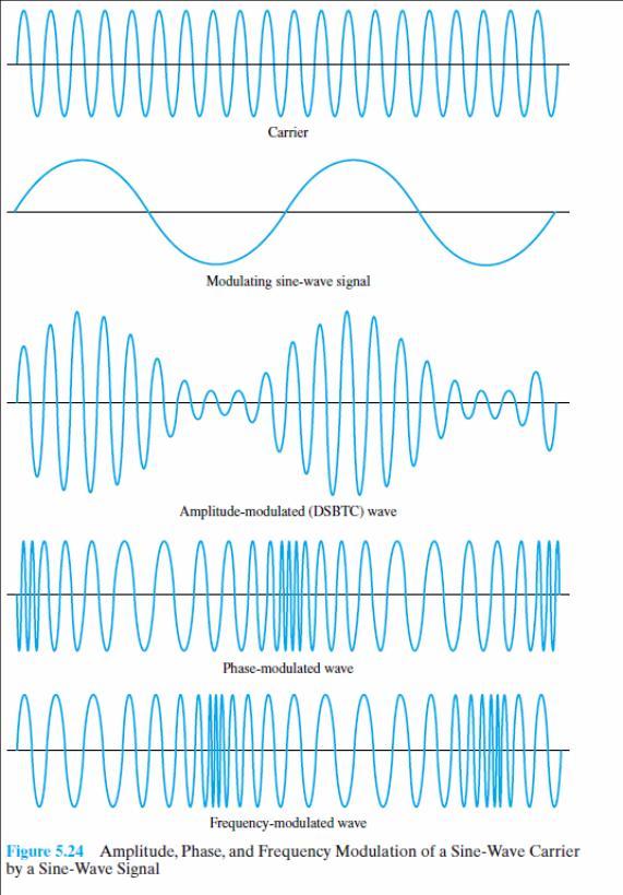
10 ANALOG DATA, ANALOG SIGNALS Modulation has been defined as the process of combining an input signal m(t) and a carrier at frequency (fc) to produce a signal s(t) whose bandwidth is (usually) centered on (fc). The principal techniques for modulation using analog data: amplitude modulation (AM), frequency modulation (FM), and phase modulation (PM).As before, the three basic characteristics of a signal are used for modulation. Amplitude Modulation Amplitude modulation (AM) is the simplest form of modulation and is depicted in Figure Mathematically, the process can be expressed as The parameter n a known as the modulation index, is the ratio of the amplitude of the input signal to the carrier. Angle Modulation Frequency modulation (FM) and phase modulation (PM) are special cases of angle modulation.the modulated signal is expressed as 10
11 11
SEN366 Computer Networks
 SEN366 Computer Networks Prof. Dr. Hasan Hüseyin BALIK (5 th Week) 5. Signal Encoding Techniques 5.Outline An overview of the basic methods of encoding digital data into a digital signal An overview of
Signal Encoding Techniques
 Signal Encoding Techniques Overview Have already noted previous chapters that both analog and digital information can be encoded as either analog or digital signals: Digital data, digital signals: simplest
Data Communications and Networking (Module 2)
") Data Communications and Networking (Module 2) Chapter 5 Signal Encoding Techniques References: Book Chapter 5 Data and Computer Communications, 8th edition, by William Stallings 1 Outline Overview Encoding
Data Communications and Networking (Module 2) Chapter 5 Signal Encoding Techniques References: Book Chapter 5 Data and Computer Communications, 8th edition, by William Stallings 1 Outline Overview Encoding
Data Encoding g(p (part 2)
") Data Encoding g(p (part 2) CSE 3213 Instructor: U.T. Nguyen 10/11/2007 12:44 PM 1 Analog Data, Digital Signals (5.3) 2 1 Analog Data, Digital Signals Digitization Conversion of analog data into digital
Data Encoding g(p (part 2) CSE 3213 Instructor: U.T. Nguyen 10/11/2007 12:44 PM 1 Analog Data, Digital Signals (5.3) 2 1 Analog Data, Digital Signals Digitization Conversion of analog data into digital
COMPUTER COMMUNICATION AND NETWORKS ENCODING TECHNIQUES
 COMPUTER COMMUNICATION AND NETWORKS ENCODING TECHNIQUES Encoding Coding is the process of embedding clocks into a given data stream and producing a signal that can be transmitted over a selected medium.
Signal Encoding Techniques
 2 Techniques ITS323: to Data Communications CSS331: Fundamentals of Data Communications Sirindhorn International Institute of Technology Thammasat University Prepared by Steven Gordon on 3 August 2015
CHAPTER 2. Instructor: Mr. Abhijit Parmar Course: Mobile Computing and Wireless Communication ( )
") CHAPTER 2 Instructor: Mr. Abhijit Parmar Course: Mobile Computing and Wireless Communication (2170710) Syllabus Chapter-2.3 Modulation Techniques Reasons for Choosing Encoding Techniques Digital data,
CHAPTER 2 Instructor: Mr. Abhijit Parmar Course: Mobile Computing and Wireless Communication (2170710) Syllabus Chapter-2.3 Modulation Techniques Reasons for Choosing Encoding Techniques Digital data,
Chapter 2: Fundamentals of Data and Signals
 Chapter 2: Fundamentals of Data and Signals TRUE/FALSE 1. The terms data and signal mean the same thing. F PTS: 1 REF: 30 2. By convention, the minimum and maximum values of analog data and signals are
2. By convention, the minimum and maximum values of analog data and signals are presented as voltages.
 Chapter 2: Fundamentals of Data and Signals Data Communications and Computer Networks A Business Users Approach 8th Edition White TEST BANK Full clear download (no formatting errors) at: https://testbankreal.com/download/data-communications-computer-networksbusiness-users-approach-8th-edition-white-test-bank/
UNIT TEST I Digital Communication
 Time: 1 Hour Class: T.E. I & II Max. Marks: 30 Q.1) (a) A compact disc (CD) records audio signals digitally by using PCM. Assume the audio signal B.W. to be 15 khz. (I) Find Nyquist rate. (II) If the Nyquist
Data Encoding. Two devices are used for producing the signals: CODECs produce DIGITAL signals MODEMs produce ANALOGUE signals
 Data Encoding Data are propagated from point to point by encoding data into signals The data may be analogue or digital Likewise the signals may be analogue or digital Two devices are used for producing
Overview. Chapter 4. Design Factors. Electromagnetic Spectrum
 Chapter 4 Transmission Media Overview Guided - wire Unguided - wireless Characteristics and quality determined by medium and signal For guided, the medium is more important For unguided, the bandwidth
Datacommunication I. Layers of the OSI-model. Lecture 3. signal encoding, error detection/correction
 Datacommunication I Lecture 3 signal encoding, error detection/correction Layers of the OSI-model repetition 1 The OSI-model and its networking devices repetition The OSI-model and its networking devices
Lecture 3 Concepts for the Data Communications and Computer Interconnection
 Lecture 3 Concepts for the Data Communications and Computer Interconnection Aim: overview of existing methods and techniques Terms used: -Data entities conveying meaning (of information) -Signals data
Physical Layer, Part 2. Analog and Digital Transmission
 CS 656 Analog/Digital, Page 1 Physical Layer, Part 2 Analog and Digital Transmission These slides are created by Dr. Yih Huang of George Mason University. Students registered in Dr. Huang s courses at
EEE 309 Communication Theory
 EEE 309 Communication Theory Semester: January 2017 Dr. Md. Farhad Hossain Associate Professor Department of EEE, BUET Email: mfarhadhossain@eee.buet.ac.bd Office: ECE 331, ECE Building Types of Modulation
Tutorial 5. Prebared by T.A,Najed Almutairi
 Tutorial 5 1. What is differential encoding? Ans q (1) differential coding is a technique used to provide unambiguous signal reception when using some types of modulation. It makes data to be transmitted
Lecture-8 Transmission of Signals
 Lecture-8 Transmission of Signals The signals are transmitted as electromagnetic waveforms. As the signal may be analog or digital, there four case of signal transmission. Analog data Analog Signal:- The
Ș.l. dr. ing. Lucian-Florentin Bărbulescu
 Ș.l. dr. ing. Lucian-Florentin Bărbulescu 1 Data: entities that convey meaning within a computer system Signals: are the electric or electromagnetic impulses used to encode and transmit data Characteristics
CSCD 433 Network Programming Fall Lecture 5 Physical Layer Continued
 CSCD 433 Network Programming Fall 2016 Lecture 5 Physical Layer Continued 1 Topics Definitions Analog Transmission of Digital Data Digital Transmission of Analog Data Multiplexing 2 Different Types of
CSCD 433 Network Programming Fall Lecture 5 Physical Layer Continued
 CSCD 433 Network Programming Fall 2016 Lecture 5 Physical Layer Continued 1 Topics Definitions Analog Transmission of Digital Data Digital Transmission of Analog Data Multiplexing 2 Different Types of
Department of Electronics & Telecommunication Engg. LAB MANUAL. B.Tech V Semester [ ] (Branch: ETE)
![Department of Electronics & Telecommunication Engg. LAB MANUAL. B.Tech V Semester [ ] (Branch: ETE)](/thumbs/86/93078052.jpg "Department of Electronics & Telecommunication Engg. LAB MANUAL. B.Tech V Semester [ ] (Branch: ETE)") Department of Electronics & Telecommunication Engg. LAB MANUAL SUBJECT:-DIGITAL COMMUNICATION SYSTEM [BTEC-501] B.Tech V Semester [2013-14] (Branch: ETE) KCT COLLEGE OF ENGG & TECH., FATEHGARH PUNJAB TECHNICAL
Department of Electronics & Telecommunication Engg. LAB MANUAL SUBJECT:-DIGITAL COMMUNICATION SYSTEM [BTEC-501] B.Tech V Semester [2013-14] (Branch: ETE) KCT COLLEGE OF ENGG & TECH., FATEHGARH PUNJAB TECHNICAL
CHAPTER 3 Syllabus (2006 scheme syllabus) Differential pulse code modulation DPCM transmitter
 Differential pulse code modulation DPCM transmitter") CHAPTER 3 Syllabus 1) DPCM 2) DM 3) Base band shaping for data tranmission 4) Discrete PAM signals 5) Power spectra of discrete PAM signal. 6) Applications (2006 scheme syllabus) Differential pulse code
CHAPTER 3 Syllabus 1) DPCM 2) DM 3) Base band shaping for data tranmission 4) Discrete PAM signals 5) Power spectra of discrete PAM signal. 6) Applications (2006 scheme syllabus) Differential pulse code
9.4. Synchronization:
 9.4. Synchronization: It is the process of timing the serial transmission to properly identify the data being sent. There are two most common modes: Synchronous transmission: Synchronous transmission relies
Digital Transmission
 Digital Transmission Line Coding Some Characteristics Line Coding Schemes Some Other Schemes Line coding Signal level versus data level DC component Pulse Rate versus Bit Rate Bit Rate = Pulse Rate x Log2
Digital to Digital Encoding
 MODULATION AND ENCODING Data must be transformed into signals to send them from one place to another Conversion Schemes Digital-to-Digital Analog-to-Digital Digital-to-Analog Analog-to-Analog Digital to
Communications I (ELCN 306)
") Communications I (ELCN 306) c Samy S. Soliman Electronics and Electrical Communications Engineering Department Cairo University, Egypt Email: samy.soliman@cu.edu.eg Website: http://scholar.cu.edu.eg/samysoliman
Communications I (ELCN 306) c Samy S. Soliman Electronics and Electrical Communications Engineering Department Cairo University, Egypt Email: samy.soliman@cu.edu.eg Website: http://scholar.cu.edu.eg/samysoliman
Basic Concepts in Data Transmission
 Basic Concepts in Data Transmission EE450: Introduction to Computer Networks Professor A. Zahid A.Zahid-EE450 1 Data and Signals Data is an entity that convey information Analog Continuous values within
Fundamentals of Data and Signals
 Fundamentals of Data and Signals Chapter 2 Learning Objectives After reading this chapter, you should be able to: Distinguish between data and signals and cite the advantages of digital data and signals
RF Basics 15/11/2013
 27 RF Basics 15/11/2013 Basic Terminology 1/2 dbm is a measure of RF Power referred to 1 mw (0 dbm) 10mW(10dBm), 500 mw (27dBm) PER Packet Error Rate [%] percentage of the packets not successfully received
Chapter 4 Digital Transmission 4.1
 Chapter 4 Digital Transmission 4.1 Copyright The McGraw-Hill Companies, Inc. Permission required for reproduction or display. 4-1 DIGITAL-TO-DIGITAL CONVERSION In this section, we see how we can represent
C06a: Digital Modulation
 CISC 7332X T6 C06a: Digital Modulation Hui Chen Department of Computer & Information Science CUNY Brooklyn College 10/2/2018 CUNY Brooklyn College 1 Outline Digital modulation Baseband transmission Line
EXPERIMENT WISE VIVA QUESTIONS
 EXPERIMENT WISE VIVA QUESTIONS Pulse Code Modulation: 1. Draw the block diagram of basic digital communication system. How it is different from analog communication system. 2. What are the advantages of
QUESTION BANK SUBJECT: DIGITAL COMMUNICATION (15EC61)
") QUESTION BANK SUBJECT: DIGITAL COMMUNICATION (15EC61) Module 1 1. Explain Digital communication system with a neat block diagram. 2. What are the differences between digital and analog communication systems?
QUESTION BANK SUBJECT: DIGITAL COMMUNICATION (15EC61) Module 1 1. Explain Digital communication system with a neat block diagram. 2. What are the differences between digital and analog communication systems?
Digital Communication System
 Digital Communication System Purpose: communicate information at certain rate between geographically separated locations reliably (quality) Important point: rate, quality spectral bandwidth requirement
Waveform Encoding - PCM. BY: Dr.AHMED ALKHAYYAT. Chapter Two
 Chapter Two Layout: 1. Introduction. 2. Pulse Code Modulation (PCM). 3. Differential Pulse Code Modulation (DPCM). 4. Delta modulation. 5. Adaptive delta modulation. 6. Sigma Delta Modulation (SDM). 7.
Time division multiplexing The block diagram for TDM is illustrated as shown in the figure
 CHAPTER 2 Syllabus: 1) Pulse amplitude modulation 2) TDM 3) Wave form coding techniques 4) PCM 5) Quantization noise and SNR 6) Robust quantization Pulse amplitude modulation In pulse amplitude modulation,
Lecture Outline. Data and Signals. Analogue Data on Analogue Signals. OSI Protocol Model
 Lecture Outline Data and Signals COMP312 Richard Nelson richardn@cs.waikato.ac.nz http://www.cs.waikato.ac.nz Analogue Data on Analogue Signals Digital Data on Analogue Signals Analogue Data on Digital
Comm 502: Communication Theory. Lecture 4. Line Coding M-ary PCM-Delta Modulation
 Comm 502: Communication Theory Lecture 4 Line Coding M-ary PCM-Delta Modulation PCM Decoder PCM Waveform Types (Line Coding) Representation of binary sequence into the electrical signals that enter the
Chapter 5: Modulation Techniques. Abdullah Al-Meshal
 Chapter 5: Modulation Techniques Abdullah Al-Meshal Introduction After encoding the binary data, the data is now ready to be transmitted through the physical channel In order to transmit the data in the
Department of Electronics and Communication Engineering 1
 UNIT I SAMPLING AND QUANTIZATION Pulse Modulation 1. Explain in detail the generation of PWM and PPM signals (16) (M/J 2011) 2. Explain in detail the concept of PWM and PAM (16) (N/D 2012) 3. What is the
Digital signal is denoted by discreet signal, which represents digital data.there are three types of line coding schemes available:
 Digital-to-Digital Conversion This section explains how to convert digital data into digital signals. It can be done in two ways, line coding and block coding. For all communications, line coding is necessary
Chapter Two. Fundamentals of Data and Signals. Data Communications and Computer Networks: A Business User's Approach Seventh Edition
 Chapter Two Fundamentals of Data and Signals Data Communications and Computer Networks: A Business User's Approach Seventh Edition After reading this chapter, you should be able to: Distinguish between
EEE 309 Communication Theory
 EEE 309 Communication Theory Semester: January 2016 Dr. Md. Farhad Hossain Associate Professor Department of EEE, BUET Email: mfarhadhossain@eee.buet.ac.bd Office: ECE 331, ECE Building Part 05 Pulse Code
Downloaded from 1
 VII SEMESTER FINAL EXAMINATION-2004 Attempt ALL questions. Q. [1] How does Digital communication System differ from Analog systems? Draw functional block diagram of DCS and explain the significance of
Overview of Digital Mobile Communications
 Overview of Digital Mobile Communications Dong In Kim (dikim@ece.skku.ac.kr) Wireless Communications Lab 1 Outline Digital Communications Multiple Access Techniques Power Control for CDMA IMT-2000 System
Digital Modulation Lecture 01. Review of Analogue Modulation Introduction to Digital Modulation Techniques Richard Harris
 Digital Modulation Lecture 01 Review of Analogue Modulation Introduction to Digital Modulation Techniques Richard Harris Objectives You will be able to: Classify the various approaches to Analogue Modulation
Computer Facilities and Network Management BUS3150 Assignment 1
 Computer Facilities and Network Management BUS3150 Assignment 1 Due date: Friday 1st September 2006 (Week 7) This Assignment has 6 questions, and you should complete answers for all 6. The Assignment contributes
Objectives. Presentation Outline. Digital Modulation Lecture 01
 Digital Modulation Lecture 01 Review of Analogue Modulation Introduction to Digital Modulation Techniques Richard Harris Objectives You will be able to: Classify the various approaches to Analogue Modulation
Digital Communication (650533) CH 3 Pulse Modulation
 CH 3 Pulse Modulation") Philadelphia University/Faculty of Engineering Communication and Electronics Engineering Digital Communication (650533) CH 3 Pulse Modulation Instructor: Eng. Nada Khatib Website: http://www.philadelphia.edu.jo/academics/nkhatib/
Philadelphia University/Faculty of Engineering Communication and Electronics Engineering Digital Communication (650533) CH 3 Pulse Modulation Instructor: Eng. Nada Khatib Website: http://www.philadelphia.edu.jo/academics/nkhatib/
CTD600 Communication Trainer kit
 kit Digital RELATED PRODUCTS v Analog s v Optical Fibers s v Digital and Analog s v Communication Electronic Trainers v Function Generator and Power Supply v Multiple Signal Generator and 1 Line Code 2
CODING TECHNIQUES FOR ANALOG SOURCES
 CODING TECHNIQUES FOR ANALOG SOURCES Prof.Pratik Tawde Lecturer, Electronics and Telecommunication Department, Vidyalankar Polytechnic, Wadala (India) ABSTRACT Image Compression is a process of removing
ECE5713 : Advanced Digital Communications
 ECE5713 : Advanced Digital Communications Bandpass Modulation MPSK MASK, OOK MFSK 04-May-15 Advanced Digital Communications, Spring-2015, Week-8 1 In-phase and Quadrature (I&Q) Representation Any bandpass
 DEPARTMENT OF COMPUTER GCE@Bodi_ SCIENCE GCE@Bodi_ AND ENIGNEERING GCE@Bodi_ GCE@Bodi_ GCE@Bodi_ Analog and Digital Communication GCE@Bodi_ DEPARTMENT OF CsE Subject Name: Analog and Digital Communication
EE3723 : Digital Communications
 EE3723 : Digital Communications Week 8-9: Bandpass Modulation MPSK MASK, OOK MFSK 04-May-15 Muhammad Ali Jinnah University, Islamabad - Digital Communications - EE3723 1 In-phase and Quadrature (I&Q) Representation
BINARY AMPLITUDE SHIFT KEYING
 BINARY AMPLITUDE SHIFT KEYING AIM: To set up a circuit to generate Binary Amplitude Shift keying and to plot the output waveforms. COMPONENTS AND EQUIPMENTS REQUIRED: IC CD4016, IC 7474, Resistors, Zener
EECS 122: Introduction to Computer Networks Encoding and Framing. Questions
 EECS 122: Introduction to Computer Networks Encoding and Framing Computer Science Division Department of Electrical Engineering and Computer Sciences University of California, Berkeley Berkeley, CA 94720-1776
 UNIT III -- DATA AND PULSE COMMUNICATION PART-A 1. State the sampling theorem for band-limited signals of finite energy. If a finite energy signal g(t) contains no frequency higher than W Hz, it is completely
QUESTION BANK. SUBJECT CODE / Name: EC2301 DIGITAL COMMUNICATION UNIT 2
 QUESTION BANK DEPARTMENT: ECE SEMESTER: V SUBJECT CODE / Name: EC2301 DIGITAL COMMUNICATION UNIT 2 BASEBAND FORMATTING TECHNIQUES 1. Why prefilterring done before sampling [AUC NOV/DEC 2010] The signal
Communications and Signals Processing
 Communications and Signals Processing Dr. Ahmed Masri Department of Communications An Najah National University 2012/2013 1 Dr. Ahmed Masri Chapter 5 - Outlines 5.4 Completing the Transition from Analog
B.E SEMESTER: 4 INFORMATION TECHNOLOGY
 B.E SEMESTER: 4 INFORMATION TECHNOLOGY 1 Prepared by: Prof. Amish Tankariya SUBJECT NAME : DATA COMMUNICATION & NETWORKING 2 Subject Code 141601 1 3 TOPIC: DIGITAL-TO-DIGITAL CONVERSION Chap: 5. ENCODING
DIGITAL COMMUNICATION
 DIGITAL COMMUNICATION TRAINING LAB Digital communication has emerged to augment or replace the conventional analog systems, which had been used widely a few decades back. Digital communication has demonstrated
Year : TYEJ Sub: Digital Communication (17535) Assignment No. 1. Introduction of Digital Communication. Question Exam Marks
 Assignment No. 1. Introduction of Digital Communication. Question Exam Marks") Assignment 1 Introduction of Digital Communication Sr. Question Exam Marks 1 Draw the block diagram of the basic digital communication system. State the function of each block in detail. W 2015 6 2 State
Assignment 1 Introduction of Digital Communication Sr. Question Exam Marks 1 Draw the block diagram of the basic digital communication system. State the function of each block in detail. W 2015 6 2 State
Signals and codes. Path and modulation
 Signals and codes Path and modulation Communication system The goal is to transfer a status message from source to destination. Signal quality is decreased by channel noise / interference Transferred message
Principles of Communications ECS 332
 Principles of Communications ECS 332 Asst. Prof. Dr. Prapun Suksompong prapun@siit.tu.ac.th 5. Angle Modulation Office Hours: BKD, 6th floor of Sirindhralai building Wednesday 4:3-5:3 Friday 4:3-5:3 Example
CHAPTER 4. PULSE MODULATION Part 2
 CHAPTER 4 PULSE MODULATION Part 2 Pulse Modulation Analog pulse modulation: Sampling, i.e., information is transmitted only at discrete time instants. e.g. PAM, PPM and PDM Digital pulse modulation: Sampling
UNIT I Source Coding Systems
 SIDDHARTH GROUP OF INSTITUTIONS: PUTTUR Siddharth Nagar, Narayanavanam Road 517583 QUESTION BANK (DESCRIPTIVE) Subject with Code: DC (16EC421) Year & Sem: III-B. Tech & II-Sem Course & Branch: B. Tech
MODULATION AND MULTIPLE ACCESS TECHNIQUES
 1 MODULATION AND MULTIPLE ACCESS TECHNIQUES Networks and Communication Department Dr. Marwah Ahmed Outlines 2 Introduction Digital Transmission Digital Modulation Digital Transmission of Analog Signal
Communication Systems Lab
 LAB MANUAL Communication Systems Lab (EE-226-F) Prepared by: Varun Sharma (Lab In-charge) Dayal C. Sati (Faculty In-charge) B R C M CET BAHAL DEPARTMENT OF ELECTRONICS & COMMUNICATION ENGINEERING Page
PULSE CODE MODULATION (PCM)
") PULSE CODE MODULATION (PCM) 1. PCM quantization Techniques 2. PCM Transmission Bandwidth 3. PCM Coding Techniques 4. PCM Integrated Circuits 5. Advantages of PCM 6. Delta Modulation 7. Adaptive Delta Modulation
PULSE CODE MODULATION (PCM) 1. PCM quantization Techniques 2. PCM Transmission Bandwidth 3. PCM Coding Techniques 4. PCM Integrated Circuits 5. Advantages of PCM 6. Delta Modulation 7. Adaptive Delta Modulation
Digital Communication System
 Digital Communication System Purpose: communicate information at required rate between geographically separated locations reliably (quality) Important point: rate, quality spectral bandwidth, power requirements
Physical Layer. Networked Systems (H) Lecture 3
 Lecture 3") Physical Layer Networked Systems (H) Lecture 3 This work is licensed under the Creative Commons Attribution-NoDerivatives 4.0 International License. To view a copy of this license, visit http://creativecommons.org/licenses/by-nd/4.0/
Physical Layer Networked Systems (H) Lecture 3 This work is licensed under the Creative Commons Attribution-NoDerivatives 4.0 International License. To view a copy of this license, visit http://creativecommons.org/licenses/by-nd/4.0/
Encoding and Framing
 Encoding and Framing EECS 489 Computer Networks http://www.eecs.umich.edu/~zmao/eecs489 Z. Morley Mao Tuesday Nov 2, 2004 Acknowledgement: Some slides taken from Kurose&Ross and Katz&Stoica 1 Questions
Data Communication (CS601)
") Data Communication (CS601) MOST LATEST (2012) PAPERS For MID Term (ZUBAIR AKBAR KHAN) Page 1 Q. Suppose a famous Telecomm company AT&T is using AMI encoding standard for its digital telephone services,
Data Communication (CS601) MOST LATEST (2012) PAPERS For MID Term (ZUBAIR AKBAR KHAN) Page 1 Q. Suppose a famous Telecomm company AT&T is using AMI encoding standard for its digital telephone services,
EC 6501 DIGITAL COMMUNICATION UNIT - II PART A
 EC 6501 DIGITAL COMMUNICATION 1.What is the need of prediction filtering? UNIT - II PART A [N/D-16] Prediction filtering is used mostly in audio signal processing and speech processing for representing
CS601 Data Communication Solved Objective For Midterm Exam Preparation
 CS601 Data Communication Solved Objective For Midterm Exam Preparation Question No: 1 Effective network mean that the network has fast delivery, timeliness and high bandwidth duplex transmission accurate
EE 400L Communications. Laboratory Exercise #7 Digital Modulation
 EE 400L Communications Laboratory Exercise #7 Digital Modulation Department of Electrical and Computer Engineering University of Nevada, at Las Vegas PREPARATION 1- ASK Amplitude shift keying - ASK - in
ECE 4203: COMMUNICATIONS ENGINEERING LAB II
 DEPARTMENT OF ELECTRICAL & COMPUTER ENGINEERING ECE 4203: COMMUNICATIONS ENGINEERING LAB II SEMESTER 2, 2017/2018 DIGITAL MODULATIONS INTRODUCTION In many digital communication systems, cable (as for data
EIE 441 Advanced Digital communications
 EIE 441 Advanced Digital communications MACHED FILER 1. Consider the signal s ( ) shown in Fig. 1. 1 t (a) Determine the impulse response of a filter matched to this signal and sketch it as a function
AMSEC/ECE
 EC6501 -DIGITAL COMMUNICATION UNIT-I SAMPLING & QUANTIZATION 1. Define Dirac comb or ideal sampling function. What is its Fourier Transform? Dirac comb is nothing but a periodic impulse train in which
KINGS COLLEGE OF ENGINEERING DEPARTMENT OF ELECTRONICS AND COMMUNICATION ENGINEERING QUESTION BANK. Subject Name: Digital Communication Techniques
 KINGS COLLEGE OF ENGINEERING DEPARTMENT OF ELECTRONICS AND COMMUNICATION ENGINEERING QUESTION BANK Subject Code: EC1351 Year/Sem: III/IV Subject Name: Digital Communication Techniques UNIT I PULSE MODULATION
EITF25 Internet Techniques and Applications L2: Physical layer. Stefan Höst
 EITF25 Internet Techniques and Applications L2: Physical layer Stefan Höst Data vs signal Data: Static representation of information For storage Signal: Dynamic representation of information For transmission
Chapter 1 Line Code Encoder
 Chapter 1 Line Code Encoder 1-1: Curriculum Objectives 1.To understand the theory and applications of line code encoder. 2.To understand the encode theory and circuit structure of NRZ. 3.To understand
Qiz 1. 3.discrete time signals can be obtained by a continuous-time signal. a. sampling b. digitizing c.defined d.
 Qiz 1 Q1: 1.A periodic signal has a bandwidth of 20 Hz the highest frequency is 60Hz. what is the lowest frequency. a.20 b.40 c.60 d.30 2. find the value of bandwidth of the following signal S(t)=(1/5)
DIGITAL COMMUNICATION. In this experiment you will integrate blocks representing communication system
 OBJECTIVES EXPERIMENT 7 DIGITAL COMMUNICATION In this experiment you will integrate blocks representing communication system elements into a larger framework that will serve as a model for digital communication
COSC 3213: Computer Networks I: Chapter 3 Handout #4. Instructor: Dr. Marvin Mandelbaum Department of Computer Science York University Section A
 COSC 3213: Computer Networks I: Chapter 3 Handout #4 Instructor: Dr. Marvin Mandelbaum Department of Computer Science York University Section A Topics: 1. Line Coding: Unipolar, Polar,and Inverted ; Bipolar;
CHETTINAD COLLEGE OF ENGINEERING & TECHNOLOGY NH-67, TRICHY MAIN ROAD, PULIYUR, C.F , KARUR DT.
 CHETTINAD COLLEGE OF ENGINEERING & TECHNOLOGY NH-67, TRICHY MAIN ROAD, PULIYUR, C.F. 639 114, KARUR DT. DEPARTMENT OF ELECTRONICS AND COMMUNICATION ENGINEERING COURSE MATERIAL Subject Name: Analog & Digital
Voice Transmission --Basic Concepts--
 Voice Transmission --Basic Concepts-- Voice---is analog in character and moves in the form of waves. 3-important wave-characteristics: Amplitude Frequency Phase Telephone Handset (has 2-parts) 2 1. Transmitter
Encoding and Framing. Questions. Signals: Analog vs. Digital. Signals: Periodic vs. Aperiodic. Attenuation. Data vs. Signal
 Questions Encoding and Framing Why are some links faster than others? What limits the amount of information we can send on a link? How can we increase the capacity of a link? EECS 489 Computer Networks
CHAPTER 2 DIGITAL MODULATION
 2.1 INTRODUCTION CHAPTER 2 DIGITAL MODULATION Referring to Equation (2.1), if the information signal is digital and the amplitude (lv of the carrier is varied proportional to the information signal, a
ANALOGUE AND DIGITAL COMMUNICATION
 ANALOGUE AND DIGITAL COMMUNICATION Syed M. Zafi S. Shah Umair M. Qureshi Lecture xxx: Analogue to Digital Conversion Topics Pulse Modulation Systems Advantages & Disadvantages Pulse Code Modulation Pulse
 Sixth Semester B.E. Degree Examination, May/June 2010 Digital Communication Note: Answer any FIVEfull questions, selecting at least TWO questionsfrom each part. PART-A a. With a block diagram, explain
This Lecture. BUS Computer Facilities Network Management. Communications Model. Encoding Techniques
 This Lecture US35 - omputer Facilities Network Management igital data, igital signals: NRL, iphase, Multilevel binary. Modulation rate, Scrambling. igital data, nalog signals Encoding techniques. SK, FSK,
DIGITAL COMMUNICATIONS LAB
 DIGITAL COMMUNICATIONS LAB List of Experiments: 1. PCM Generation and Detection. 2. Differential Pulse Code modulation. 3. Delta modulation. 4. Time Division Multiplexing of 2band Limited Signals. 5. Frequency
CSE 123: Computer Networks Alex C. Snoeren. Project 1 out Today, due 10/26!
 CSE 123: Computer Networks Alex C. Snoeren Project 1 out Today, due 10/26! Signaling Types of physical media Shannon s Law and Nyquist Limit Encoding schemes Clock recovery Manchester, NRZ, NRZI, etc.
CS601-Data Communication Latest Solved Mcqs from Midterm Papers
 CS601-Data Communication Latest Solved Mcqs from Midterm Papers May 07,2011 Lectures 1-22 Moaaz Siddiq Latest Mcqs MIDTERM EXAMINATION Spring 2010 Question No: 1 ( Marks: 1 ) - Please choose one Effective
Multiplexing Module W.tra.2
 Multiplexing Module W.tra.2 Dr.M.Y.Wu@CSE Shanghai Jiaotong University Shanghai, China Dr.W.Shu@ECE University of New Mexico Albuquerque, NM, USA 1 Multiplexing W.tra.2-2 Multiplexing shared medium at
OptiSystem applications: Digital modulation analysis (PSK)
") OptiSystem applications: Digital modulation analysis (PSK) 7 Capella Court Nepean, ON, Canada K2E 7X1 +1 (613) 224-4700 www.optiwave.com 2009 Optiwave Systems, Inc. Introduction PSK modulation Digital
OptiSystem applications: Digital modulation analysis (PSK) 7 Capella Court Nepean, ON, Canada K2E 7X1 +1 (613) 224-4700 www.optiwave.com 2009 Optiwave Systems, Inc. Introduction PSK modulation Digital
CSCI-1680 Physical Layer Rodrigo Fonseca
 CSCI-1680 Physical Layer Rodrigo Fonseca Based partly on lecture notes by David Mazières, Phil Levis, John Janno< Administrivia Signup for Snowcast milestone Make sure you signed up Make sure you are on
Pulse Code Modulation
 Pulse Code Modulation EE 44 Spring Semester Lecture 9 Analog signal Pulse Amplitude Modulation Pulse Width Modulation Pulse Position Modulation Pulse Code Modulation (3-bit coding) 1 Advantages of Digital