TM &P TECHNICAL MANUAL OPERATOR S, ORGANIZATIONAL, DIRECT SUPPORT AND GENERAL SUPPORT MAINTENANCE MANUAL (INCLUDING REPAIR PARTS
|
|
|
- Jacob Parks
- 6 years ago
- Views:
Transcription
1 TM &P TECHNICAL MANUAL OPERATOR S, ORGANIZATIONAL, DIRECT SUPPORT AND GENERAL SUPPORT MAINTENANCE MANUAL (INCLUDING REPAIR PARTS AND SPECIAL TOOLS LIST) FOR TRANSPONDER SET, TEST SET AN/APM-378 (NSN ) This copy is a reprint which includes current pages from Change 1. HEADQUARTERS, DEPARTMENT OF THE ARMY SEPTEMBER 1980
2 WARNING Do not make internal connections or adjustments alone. Always have another person available to help in case of an accident. Dangerous voltage exists in this equipment. Injury may result if personnel fail to observe safety precautions. Use a common ground to connect the test set equipment under test and additional test equipments to the power source ground before applying power. ELECTROMAGNETIC RADIATION HAZARDS EXIST AT THE WAVEGUIDE OUTPUT FROM THE POWER AMPLIFIER AND WITHIN THE DIRECTIONAL PATTERN OF THE ANTENNA! DO NOT STAND IN THE DIRECT PATH OF THE ANTENNA FOR WORK ON WAVEGUIDES WHILE POWER IS ON. Adequate ventilation should be provided while using TRICHLOROTRI- FLUOROETHANE. Prolonged breathing of vapor should be avoided. The solvent should not be used near heat or open flame; the products of decomposition are toxic and irritating. Since TRICHLOROTRIFLUORO- ETHANE dissolves natural oils, prolonged contact with skin should be avoided. When necessary, use gloves which the solvent cannot penetrate. If the solvent is taken internally, consult a physician immediately SAFETY STEPS TO FOLLOW IF SOMEONE IS THE VICTIM OF ELECTRICAL SHOCK. DO NOT TRY TO PULL OR GRAB THE INDIVIDUAL. IF POSSIBLE, TURN OFF THE ELECTRICAL POWER. IF YOU CANNOT TURN OFF THE ELECTRICAL POWER, PULL, PUSH, OR LIFT THE PERSON TO SAFETY USING A WOODEN POLE OR A ROPE OR SOME OTHER INSULATING MATERIAL. SEND FOR HELP AS SOON AS POSSIBLE. AFTER THE INJURED PERSON IS FREE OF CONTACT WITH THE SOURCE OF ELECTRICAL SHOCK, MOVE THE PERSON A SHORT DISTANCE AWAY AND IMMEDIATELY START ARTI- FICIAL RESUSCITATION.
3 TM & P C1 CHANGE No. 1 HEADQUARTERS DEPARTMENT OF THE ARMY Washington DC, 16 November 1982 Operator s, Organizational, Direct Support And General Support Maintenance Manual (Including Repair Parts And Special Tools List) FOR TRANSPONDER SET, TEST SET AN/APM-378 (NSN ) TM &P, 30 September 1980 is changed as follows: 1. New or changed material is indicated by a vertical bar in the margin of the page. 2. Added or revised illustrations are indicated by a vertical bar in front of the figure caption. 3. Remove and insert pages as indicated below: Remove Insert i,ii and iii i, ii and iii /(0-2 blank) 2-7(2-8 blank) (2-8 blank) 2-15 and through and and (3-32 blank) (3-32 blank) 4-1 and and and and through through through through (4-24 blank) (4-24 blank) A-l and A A-l and A-2 4. File this change sheet in front of the publication for reference purposes.
4 By Order of the Secretary of the Army: Official: E. C. MEYER General United States Army Chief of Staff ROBERT M. JOYCE Major General, United States Army The Adjutant General Distribution: To be distributed in accordance with DA Form 12-36A, Organizational Maintenance Requirements for AN/APM- 123.
5 TECHNICAL MANUAL No &P HEADQUARTERS DEPARTMENT OF THE ARMY Washington, DC, 30 September 1980 I I OPERATOR S, ORGANIZATIONAL, DIRECT SUPPORT AND GENERAL SUPPORT MAINTENANCE MANUAL (INCLUDING REPAIR PARTS AND SPECIAL TOOLS LIST) FOR TRANSPONDER SET TEST SET AN/APM378 NSN REPORTING ERRORS AND RECOMMENDING IMPROVEMENTS You can help improve this manual. If you find any mistakes or if you know of a way to improve the the procedures, Please let us know. Mail your letter, DA Form 2028 (Recommended Changes to Publications and Blank Forms), or DA Form located m the back of this manual direct to Commander, US Army Communicatios Electronics Command and Fort Monmouth, ATTN: DRSEL-ME-MQ, Fort Monmouth, NJ In either case, a reply will be furnished direct to you. TABLE OF CONTENTS SECTION 0 INTRODUCTION Scope Index of Tecnical Publications Maintenance Forms, Records and Reports Reporting Equipment Improvement Recommendations (EIR) Adminisrative.. Storagc Destruction of Army Electronics Materiel Hand Receipt (-HR) Manual INTRODUCTION General Scope and Arrangement of Manual Serialization Equipment Function Record of Applicable Technical Directives EQUIPMENT DESCRIPTION General Equipment Description and Capabilities Equipment Supplied Equipment Required but Not Supplied Principles 0f Operation Functioanl Operation SIF Modes Mode-3 and Mode-Test Emergency Mode-4 Operation SIF Self-Test Mode Mode-4 Self-Test RF Module A Lamp Tast Mode Power Supply Circuits Change 1
6 SECTION I. II. III. IV. APPENDIX A. B. C. D. E. F. Operation Preventive Maintenance Checks and Services (PMCS) Routine PMCS Services INTERMEDIATE MAINTENANCE INSTRUCTIONS General Test Equipment Required Checkout Troubleshooting RF Section, Troubleshooting Bulk Items Consumable List Disassembly Removal of Digital Printed Circuit Cards Removal of RF Module and Submodules Removal of Chassis Assembly from Panel Cleaning Inspection Repair Limits Assembly Adjustment Testing and Calibration Wiring/Schematic Data INTERMEDIATE TESTING PROCEDURES General Test Equipment Required Intermediate Checkout Procedures PRESERVATION, PACKAGING, AND PREPARATION FOR USE General Preservation Requirements Preparation for Use ILLUSTRATED PARTS BREAKDOWN INTRODUCTION Scope Purpose and Use Section I. Introduction Section II. Group Assembly Parts List General Section III. Numerical Index General Figure and Index Number Column Codes Column Section IV. Reference Designation Index Abbreviations How to Use the Illustrated Parts Breakdown Vendor Codes GROUP ASSEMBLY PARTS LIST NUMERICAL INDEX REFERENCE DESIGNATION INDEX REFERENCE COMPONENTS OF END ITEM LIST ADDITIONAL AUTHORIZATION LIST MAINTENANCE ALLOCATION REPAIR PARTS LIST EXPENDABLE SUPPLIES AND MATERIALS LIST Page A-1 B-1 C-1 D-1 E-1 F-1 LIST OF ILLUSTRATIONS Number Title 2-1 Transponder Set Test Set AN/APM Test Set to Aircraft Transponder Relationships, Block Diagram Transponder Set Test Set AN/APM-378, Functional Block Diagram Timing Diagram, Encode Cycle (SIF Mode 3) Page ii
7 Number Title Timing Diagram, Decode Cycle (SIF Reply Code 7777) Transponder Set Test Set AN/APM-378, Controls, Indicators, and Con- nectors Test Set, General Trouble Analysis Diagram (2 Sheets) RF Section, Trouble Analysis Diagram RF Module, Setup Diagram for T7 and T8 Frequency Tests RF Module, Setup Diagram for T7 and T8 Power Tests RF Module, T21 Setup Diagram Power Supply Circuits, Schematic Diagram Motherboard, Track Wiring, Schematic Diagram (2 Sheets) RF Module A-1 PCB Track Wiring Diagram Transponder Set, Test Set AN/APM-378, Front Panel Schematic Diagram Special Jumper Cable for RF Circuits Maintenance (3 Sheets) Power Supply Checks, Test Setup Typical Test Setup Connections Mode 4 Pretrigger Check, Test Setup Mode 4 Typical Test Setup Connections Special Mode 4 Calibration Connector Transponder Set Test Set AN/APM Test Set Cover Transponder Set Test Set AN/APM-378, Rear View Power Cable (PN ) Power Cable Assembly (PN ) Front Panel Assembly Cable Assembly Chassis Assembly RF Module Assembly Module Assemblies LIST OF TABLES Transponder Set Test Set AN/APM-378, Equipment Characteristics and Capabilities Transponder Set Test Set AN/APM-378, Equipment Supplied Transponder Set Teat Set AN/APM-378, Equipment Required but Not Supplied Transponder Set Test Set AN/APM-378, Characteristics Transponder Set Test Set AN/APM-378, Operating Controls, Indicator, and Connectors Transponder Set Test Set AN/APM-378 Operating Instructions Preventive Maintenance Checks and Services Transponder Set Test Set AN/APM-378, Maintenance Teat Equipment Required Transponder Set Test, Set AN/APM-378, Maintenance Teat Equipment Required (Army) Troubleshooting Analysis, Measurement Parameters RF Section, Troubleshooting Analysis, Measurement Parameters Inspection Suggestions Transponder Set Test Set AN/APM-378, Wiring List Cable Assembly W3, Wiring Data Multipin Connectors J1 and J2, Pin Functions RF Module A-1, Coaxial Cable Connections Transponder Set Test Set AN/APM-378, Teat Equipment Required Radar Test Set AN/TPM-25A Controls Transponder Set Test Set AN/APM-378, AN/TPM-25 Procedures Transponder Set Test Set AN/APM-378, Adjustments Page Change 1 iii
8
9 SECTION 0 INTRODUCTION 0-1. SCOPE This manual describes Transponder Set Test Set AN/APM- 378 and provides instructions for operation and maintenance INDEX OF TECHNICAL PUBLICATIONS Refer to the latest issue of DA Pam to determine whether there are new editions, changes, or additional publications pertaining to the equipment MAINTENANCE FORMS, RECORDS, AND REPORTS a. Reports of Maintenance and Unsatisfactory Equipment. Department of the Army forms and procedures used for equipment maintenance will be those prescribed by TM , The Army Maintenanace Management System. b. Report of Pakaging and Handling Deficiencies. Fill out and forward SF 364 (Report of Discrepancy (ROD)) as prescribed in AR 735-1l-2/DLAR / NAVMATINST /AFR /MC E. c. Discrepancy in Shipment Report (DISREP) (SF 361). Fill out and forward Discrepancy in Shipment Report (DISREP) (SF 361) as prescribed in AR 55-38/NAVSUP- INST B/AFR 75-18MCO C/DLAR REPORTING EQUIPMENT IMPROVEMENT RECOMMENDATIONS (ERI) If your Transponder Set Test Set AN/APM-378 needs improvement, let us know. Send us an EIR. You, the user, are the only one who can tell us what you don t like about your equipment. Let us know why you don t like the design. Tell us why a procedure is hard to perform. Put it on an SF 368 (Quality Deficiency Report). Mail it to Commander, US Army Communications-Electronics Command and Fort Monmouth, ATTN: DRSEL-ME-MQ Fort Monmouth, NJ We ll send you a reply ADMINISTRATIVE STORAGE Administrative storage of equipment issued to and used by Army activities will have preventive maintenance performed in accordance with the PCMS charts before storing. When removing the equipment from administrative storage the PCMS should be performed to assure operational readiness. Disassembly and repacking of equipment for shipment or limited storage are covered in paragraphs 5-4 through DESTRUCTION OF ARMY ELECTRONICS MATERIEL Destruction of Army electronics materiel to prevent enemy use shall be in accordance with TM HAND RECEIPT (-HR) MANUALS This manual has a companion document with a TM number followed by -HR)) which stands for hand receipt). The TM HR consists of preprinted hand receipts (DA Form 2062) that list end item related equipment (i.e. COE1, BII and AAL) you must account for. As an aid to property accountability y, additional -HR manuals may be requisitioned from the US Army Adjutant General Publications, Baltimore, Maryland, in accordance with the procedures in Chapter 3. AR and DA Pam Change 1 0-1/(0-2 Blank)
10
11 SECTION 1 INTRODUCTION 1-1 GENERAL This manual contains intermediate level maitenance instructions with illustrated parts breakdown for the Transponder Set Test Set AN/APM-378 (also referred to herein as test set). This equipment is manufactured by The Bendix Corporation, Commutications Division, Baltimore, Maryland under Contract N C SCOPE AND ARRANGEMENT OF MANUAL Data within this manual is divided into six section. Section 1 contains general information; Section 2 gives equipment description, theory and operating information. Section 3 gives the intermediate maintenance instructions for troubleshooting, disassembly, repair and reassembly, of the test set. Section 4 contains intermediate test procedures. Section 5 of the manual contains preservation, packaging, storage, and use information. Section 6 of the manual contains the illustrated parts breakdown (IPB) for the equipment SERIALIZATION The information contained in this manual is applicable to all Transponder Set Test Sets AN/APM-378 manufactured under Contract N C EQUIPMENT FUNCTION The AN/APM-378 test set is an accept/reject type tester, used at the flightline to provide rapid indication of the operational status of AIMS Mark XII transponder equipments. The test set is capable of either direct- connected or radiated-path testing of transponders. In operation, the AN/APM-378 equipment generates interrogation pulses, and feeds (or radiates) them to the aircraft transponder equipment. The resulting reply pulses from the transponder are then received and analyzed by the AN/ APM-378; if correct replies were generated, the test set gives a visual ACCEPT indication Interrogation modes which can be checked by the test set include modes 1, 2, 3/A, C, test, and mode 4. In addition to checking for correct reply pulse sets generated by the aircraft transponder (with proper spacings), the AN/APM-378 also performs checks of the transponder transmitter frequency and power output, and emergency and I/P operability The AN/APM-378 test set is contained in a rugged combination case. Its circuits include self-check capability, to determine that the test set is fully operable, prior to its flight-line use. The test set is designed to check AIMS transponders, including the following: RT-859/APX-72; RT-859A/ APX-72; RT-859B/APX-72 (Diversity); AN/APX-64; KY-532A; KY-533A; AN/APX- 93; UPA-59; UPA-59A, UPA-60; RT-1156/ APX-100, RT-l157/APX-100, and RT- 1063/APX For detailed listing of the characteristics and capabilities of the test set, refer to Section RECORD OF APPLICABLE TECHNICAL DIRECTIVES, A record of applicable Technical Directives is provided to identify the Technical Directive number(s), date of issue, title and the publication date of the manual change/revision/supplement which has incorporated new operation/maintenance information for the equipment on which the work described in the technical directive has been accomplished. 1-1
12 RECORD OF APPLICABLE TECHNICAL DIRECTIVES TD No. Date Title Change/Revision Supplement Date Sec March 1975 Improve EMI 30 Sept 1976 Capability (ECP-1R2) 1-2
13 SECTION 2 EQUIPMENT DESCRIPTION 2-1. GENERAL This section contains detailed listings of the characteristics and capabilities of the Transponder Set Test Set AN/Al?M Tables of equipment supplied, and euipment required but not supplied are part of this section. Principles of operation, functional operation, and operating information are also contained in this section EQUIPMENT DESCRIPTION AND CAPABILITIES The AN/APM-378 test set is a portable accept/reject tester, housed in a rugged combination case. A detachable cover of the case, in addition to protecting the controls and indicators of the test set, contains the accessory cables, and the antenna assembly. Power for the test set is obtained from 115 V ac or 28 V dc power sources at the flightline locations where the test set is employed. Figure 2-1 shows the overall view of AN/ APM-378 test set Table 2-1 lists the characteristics and capabilities of the AN/APM-378. The test set (completely solid state) employs strip-line rf circuits and integratedcircuits to provide maximum ruggedness and highest reliability. Built-in self-test circuits determine the test set operational readiness, prior to testing of transponders. Controls and indicators of the test set have been designed for simplicity of operation, and can be correctly manipulated even by oerators wearing arctic gloves EQUIPMENT SUPPLIED Table 2-2 lists the equipment and components supplied as part of the Trans - ponder Set Test Set AN/APM EQUIPMENT REQUIRED BUT NOT SUPPLIED Table 2-3 lists equipment/components which are required for maintenance or calibration of the Transponder Set Test Set AN/APM-378, but which are not supplied as part of the test set PRINCIPLE S OF OPERATION Figure 2-2 shows the basic relationship of the test set to the transponder being checked. The test set transmits interrogation pulses to the aircraft transponder (via rf radiation from the antenna, or via direct-connected rf cables). If it is operating correctly, the transponder produces reply pulses and transmits them back to the test set. Internal circuits of the test set then check the received replies for proper pulse spacing/presence/absence, etc. For each check made by the test set, an ACCEPT or REJECT indication is given to indicate acceptable or unacceptable operation of the aircraft transponder When making Mode 4 tests, the test set generates a pretrigger, which is applied to the Interrogator Computer KIR-1A. The KIR-1A responds with a Mode 4 Interrogation Video Word, which modulates the test set transmitter, The resulting Mode 4 interrogation is sent to the transponder, which applies it to the associated IFF computer equipment. If the coding is correct the transponder replies to the test set. The resulting signals in the test set are then applied to the KIR-1A as Reply Video, which generates a TDV signal. This TDV signal, and a GTC pulse are fed from the KIR-1A to the test set; both signals must occur coincidently in order to generate an ACCEPT indication in the test set. 2-1

14 Figure 2-1. Transponder Set Test Set AN/APM
15 Physical Characteristics: Table 2-1. Transponder Set Test Set AN/APM-378, Equipment Characteristics and Capabilities Overall Dimensions Overall Volume Weight Input Power Requirements Environmental Limitations Test Set Functions Transponder Modes Checked by Test Set.. Input Pulse Signals Required by Test Set.. (Mode 4 only) Output Pulse Signals Produced by Test Set inches long inches wide 12.0 inches high 0.8 cubic feet 29 pounds 115 V ac, 60 or 400 Hz at 0.4 A 28 V dc at l.0a -40 to +71 degrees C (operating), -62 to +85 degrees C (storage) Lamp-Test, Self-Test, System, Frequency/Power, Emergency, and I/P Mode 1, 2, 3/A, C, (with or without SPI puke), Test, 4 (with use of interrogator Computer KIR-1A) Mode 4 Video Interrogation Word, SLS Pulse, GTC Pulse, and TDV Pulse Mode 4 Pretrigger, and Reply Video Table 2-2. Transponder Set Test Set AN/APM-378, Equipment Supplied ITEM Transponder Set Test Set Panel and Chassis Assembly Antenna Assembly Cable, AC Power Cable, DC Power Special purpose Cable RF Cable (25 feet) RF Cable (6 inches) Resistive Load NOMENCLATURE AN/APM-378 W1 W2 W3 W4 W5 AT1 PART NUMBER Table 2-3, Transponder Set Test Set AN/APM-378, Equipment Required but Not Supplied QTY ITEM NOMENCLATURE E 1 Special Jumper Cable Figure Mode 4 Calibration Connector Figure
16 Figure 2-2. Test Set to Aircraft Transponder Relationships, Block Diagram In the Mode 4 self-test, the KIR-1A may, or may not be connected to the test set. With the KIR-1A connected, signals are routed from the test set to the Interrogation Computer in a manner similar to actual Mode 4 system operation. If the KIR-1A is not connected during the Mode 4 self-test, the test set supplies signals which effectively test its own Mode 4 circuits The preceding discussion describes the general basic system-testing operation of the test set. The test set checks three types of transponders; namely, singlechannel, diversity-type, and lobing systems. For all types of systems, any mode may be selected for test. In addition to MODE selection, the test set controls the FUNC- TION to be tested. Functions include; system testing (basic); VP; emergency; lamptesting; and frequency/power checks When the test set is first energized, the FUNCTION switch is placed in its SELF- TEST position. This exercises the test set circuits, and yields an ACCEPT indication (lamp lights) if all circuits are operating correctly. Once the self-test has established correct test set operation, system-testing operations can be accomplished, knowing that a REJECT indication (lamp lights) must be caused by incorrect operation of the transponder The test set SLS pulse control enables the operator to check the transponder for proper response in the presence or absence of the SLS pulse Table 2-4 lists the specific inputs/ outputs of the test set and their pertinent characteristics FUNCTIONAL OPERATION Figure 2-3 shows the functional block diagram of the test set. This set consists of two major sections; the digital section (composed of four nonreparable solid-state modules) and the rf section (composed of rf module Al and its three nonreparable rftype subassemblies) Circuit operation occurs in two basic cycles; encode, and decode. During each of these cycles, signals are timed (clocked) by internal clock signals, whose frequency varies according to the cycle of operation. Basic signal timing is derived from an internal 22-MHz oscillator, whose output is counted-down to the required CLOCK rate. During SIF interrogation modes (in the encode cycle), the CLOCK rate is 1 MHz; for Mode 4 interrogation the CLOCK rate is 555 khz. During the decode cycle of operation, the CLOCK rate changes to 690 khz for the SIF mode replies (or remains at the 555 khz rate for the Mode 4 replies) During the encode cycle, the digital circuits generate coded output pulse sets, whose timing and coding are determined by the front panel control settings. These digital signals are then fed to the rf module circuits, where they gate (modulate) rf oscillator stages to produce output interrogation rf pulses (at 1030 MHz). Timing of 2-4

17 Table 2-4. Transponder Set Test Set AN/APM-378, Characteristics Duty Cycle... 1% Receiver:. Antenna: Beamwidth - Horizontal...., to 80 (3 db points) Beamwidth - Vertical to +50 (amplitude variation less than 6 db Interrogation Pulses: Mode 1 2 3/A C Test 4 Reply Pulses - Analysis Capability: Pulse Spacing Variation (from correct nominal) Side Lobe Suppression..., Control Pulse Spacing Mode SIF and I/P: I/P I/P Emergency/Frequency/Power Checks: Frequency Pulse Width Spacing Mode 4 spacing - REJECT (With or without F3 pulse.) SLS control pulse alternates between 0 and 11 ACCEPT indication for correct replies to > 80% or 40% (see paragraph 2-39) of interrogations. Mode C, with or without SIF pulse. Mode 1, 2, 3/A, Test. (SIF Modes). Power Self-Test Checks test set circuits for all modes of operation. 2-5
18 the output rf pulses is the same as that of the digital signals which control them. From the rf module output, the rf pulses are fed to the transponder under test (either via the antenna, or via direct-connect cables), Upon completion of the transmission of output rf pulses, the encode cycle ends, and the circuits switch to their decode cycle During the decode cycle, rf reply pulse sets are received from the transponder under test. In the rf module circuits, the reply pulses are detected (demodulated) to produce video-type pulses, whose coding and timing are that generated by the transponder under test. In the rf module, the frequency and relative power of the reply pulses are also checked. The video pulses from the detector circuits are then fed to the digital circuits, which now check the parameters of coded reply pulses. The parameters being checked include pulse timing, checks for extraneous or missing pulses, correct SLS action, etc. If all parameters of the reply are correct (for the specific mode and code used for interrogation), the digital circuits light an ACCEPT lamp on the front panel. Conversely, if any, parameter is incorrect, the circuits light a REJECT lamp Actually, the ACCEPT or REJECT lamps are not lighted on the basis of a single testing cycle (encode and decode cycle). Basic testing cycles are repeated at the rate of 257 cycles per second. This repetitive cycling is required to determine if a transponder replies correctly to a specified percentage of interrogations. During testing, the digital circuits determine the percentage of correct replies (of the total number of test interrogations made), and light the REJECT lamp if the transponder fails to meet the specified percentage The rf module circuits also check the frequency and relative power of the reply pulses received from the transponder. If frequency and power are within specifications, a signal is fed to the digital circuits, to cause lighting of the ACCEPT lamp. If either the frequency or power of the reply pulses is incorrect, the REJECT lamp is lighted. During SYSTEM testing, the frequency/power signal is fed to the digital circuits, which also examine the reply pulses for other parameters Other modes of the test set include lamp-testing and self-testing modes. In the lamp-test mode, signal levels are applied to the stages controlling the indicator lamps, to cause them to light; if any lamp fails to light during this check, it is possibly burned out, and maintenance actions are required. For the self-test mode operation, the digital circuits generate special interrogation pulses and apply them to the rf module circuits, where they produce output of interrogation pulses. The resulting rf output pulses are demodulated in the receiver stages, and fed to digital stages which check for known parameters of the special self-test signals. If all stages of the test set are operating correctly, they will cause an ACCEPT indication during the self -test mode The following discussions briefly describe signals and actions occurring in the test set circuits, for various modes of operation. For these discussions refer to figures 2-4 and 2-5 for timing diagrams of the various signals, and to the functional block diagram of figure 2-3. First, the dig. ital circuit operations (by modes) are discussed, followed by discussions of the rf module, and the power supply circuits of the test set. 2-27, SIF MODES. For SIF mode testing, encode-cycle signals are clocked at 1-MHz rate (l-microsecond period), and decodecycle actions are clocked at 690-kHz rate (1. 45-microsecond period). When the TEST switch is placed at ON position during an SIF mode test, the following actions occur At the beginning of the encode cycle, a DATA pulse appears at U3-TP1, and is loaded into a register, by the next-occurring CLOCK pulse. This generates a To pulse (at U2-TP4), which initiates the P1 interrogation pulse. The DATA pulse is shifted through the register stages (at the CLOCK (U4-TP2) to initiate the P2 interrogation pulse. Farther down the register-stage chain, the DATA pulse is again tapped-out, 2-6
19 TM &P Figure 2-3. Transponder Set Test Set AN/APM-378, Functional Block Diagram. (Located in back of manual). 2-7/(2-8 Blank)
20
21 Figure 2-4. Timing Diagram, Encode Cycle (SIF Mode 3) to initiate the P3 interrogation pulse; the specific register tap-out point for the P3 pulse (determined by the MODE selection switch) produces the specified spacing of the P1 and P3 pulses for the mode selected The three pulses (P1, P2, and P3) are regenerated into standard-width INTERRogation pulses (at U2-TP8) and are fed to the rf module circuits where they gate (modulate) the 1030-MHZ rf transmitter circuits. Additionally, the P2 pulse is applied from U4-TP1 to the SLS GATE circuits of the rf module, to develop the side lobe function The P3 pulse so developed in the digital circuits performs several functions within those modules. It causes the RESET INT signal (U1-TP5) and the RESET SR signal (U1-TP10) to clear the register stages of all encode-cycle data. The trailing edge of the P3 pulse (at U3-TP6) causes changing of the CLOCK rate to 690 khz for the following decode period. Also, the P3 pulse triggers a delayed (
22 Figure 2-5. Timing Diagram, Decode Cycle (SIF Reply Code 7777) microseconds) VIDEO GATE signal (U3- TP3). After the delay period, the VIDEO GATE from U3-TP3 is applied to the rf module and gates the local oscillator for 8.5 microseconds, activating the receive r circuits. In addition to these previous actions, the P3 pulse triggers generation of a REPLY GATE (U3-TP4), which inhibits any interrogations during the decode cycle Now during the decode cycle, when reply pulses (at 1090 MHz) are received from the transponder under test, they are downconverted to 30 MHz, detected (demodulated) in the rf module circuits, and their frequency and power are checked. (Frequency must be dbm.) Provided the reply pulses meet the frequency/power requirements, they are sent to the digital section as the REPLY SAMPLE (U3-TP10). At this time, the reply pulse width is normalized to form the DATA signals at U3-TP1, and the CLOCK is desynchronized with the DATA to insure correct loading of the DATA into shiftregister stages. Receipt of reply pulses also causes hold-open of the VIDEO GATE (at U3-TP3) such that the local oscillator (and receive function) will be enabled for at least reply pulse The DATA (at U3-TP1) is clocked through shift-register stages of U2, and appears at U1-TP6 as the DATA-2 input to shift-registers of U1. When the DATA-2 bit corresponding to the F1 reply pulse appears at a specified tap on the last shift-register stage, a parity strobe is generated. This strobe enables a parity circuit to then check for absence or presence of the reply frame and coding pulses (as applicable), The parity circuit compares the reply pulses received against a reply code set by by positioning of the CODE SELECT switches on the test set front panel; the received reply must match that set by the CODE switches, to produce an ACCEPT condition. Additionally, F3, F4, and F5-to-F8 parity comparisons are made for pulses following the F2 pulse. If all comparison conditions are met (at the parity strobe time), a SIF GO strobe is generated (U1-TP4) and sent to the evaluator board U4 circuits As the F1 pulse of the DATA-2 signal is shifted past the parity-strobe tap of U1, a RESET SR pulse (U1-TP10) is generated 2-10
23 to clear all register stages. Basically, this actions ends the decode-cycle. PRF circuits within the U3 module will determine when the next encode-cycle (interrogation) is to begin, and will at that time change the CLOCK rate to 1 MHz and generate a P1 pulse on the DATA line (at U3-TP1), to start the next encodecycle. Encode (Interrogation) and decode (reply) cycles and actions then repeat, in the manner described thus far for one encode/ decode cycle. The PRF circuits of U3 control the rate of encode/decode repetition such that iterrogation/reply-checking occurs at a rate of 257 cycles per second Each time a correct reply is obtained from the transponderundertest, the resulting SIF GO strobe is fed to the evaluator U4 circuits, as mentioned. An integrator/ comparator circuit of U4 measures the percentage of times that correct replies are received (for the number of times the transponder is interrogated), and causes the ACCEPT lamp to light. if the correct-reply rate is greater than 80 percent of the interrogation rate. The 80-percent correctreply criteria applies for testing of singlechannel and diversity transponders. When testing lobing-type transponders, a lower threshold voltage is applied to the U4 comparator circuit, to cause the ACCEPT indication to be indicated for correct-reply rates greater than 40 percent of the interrogation rate MODE-3 AND MODE-TEST EMER- GENCY. Operation of the test set circuits for Mode-3 and Mode-Test Emergency is similar to that described for the SIF modes. However, for these M3 and MT Emergency operations, the code is always The proper comparison code states for the parity comparison are then generated by the A&B ENABLE Ul-TP9) and the C&D) DIS- ABLE code selector (which bypasses the front panel CODE SELECT switches). In Mode C, there is no emergency function. Also, in Mode C, the test set will give an ACCEPT indication, either with or without a SPI pulse MODE-4 OPERATION. For Mode-4 (M4) operation, the test set is used in conjunction with an Interrogator Computer KIR-1A. The KH3-1A is connected to the test set via the M4 cable supplied with the test set CAUTION Use only the cable provided; use of other cables may result in damage to the AN/APM-378. Additionally, during M4 operation, the front panel FUNCTION switch is placed in the SYSTEM position, and the MODE switch is set for MODE 4. During M4 Operation, the CLOCK rate in the test set is 555 khz (1.8- microsecond period). In the same manner as for the SIF modes discussed previously, the encode-cycle of operation begins with a counted-down CLOCK signal generating the To Pulses (U2-TP4). This action sends the M4 PRETRIGGER to the KIR-1A, which then returns the M4 VIDEO interrogation word. The M4 VIDEO pulses are shaped in U4 circuits, and are then sent to the U2 circuits (U2-TP10). From U2, the pulses are applied as Interrogation pulses (U2-TP8) to the rf module to modulate the 1030-MHz transmitter stages In response to the M4 PRETRIGGER, the KIR-lA equipment also applies an M4 GTC signal to the test set. This signal triggers an approximately 78-microsecond gate to yield a GTC GO signal (U3-TP9), which in turn provides a VIDEO GATE (U3-TP3) that enables a 3-pulse decoder in the U4 module As for SIG mode operation, the transmitter rf pulses during the encode-cycle cause the transponder under test (and its associated Interrogator Computer equipment) to generate reply pulses, These reply pulses are checked for correct power and frequency in the rf module circuits, and if correct, are detected and sent as the REPLY SAMPLE data to the digital section (U3-TP10). Upon receipt of the REPLY SAMPLE data, CLOCK is desynchronized and the data is loaded into shift-register stages. At this time, the 3- pulse decoder that was enabled in response to the GTC GO signal (U3-TP9) checks for coincidence of To (U2-.TP4), the 1-microsecond tap signal (U2-TP2), and the 2-microsecond tap signal (U4-TP2). If correct coindence occurs for this check, a pulse is applied to one input of an AND circuit of U The REPLY SAMPLE data, after regeneration, is also applied to the KIR-lA Interrogator Computer as the M4 REPLY 2-11
24 VIDEO. If the reply is correct, the KIR-lA feeds a TDV signal to the test set, where it is applied to the second input of the U4 AND circuit (whose other input is the coincidencecheck pulse). With both inputs receiving correct signals, the AND circuit then enables the evaluator U4 circuits to count the reply as a correct reply (in the same manner as it counts SIF GO pulses for SIF modes). Thus the U4 circuits will light an ACCEPT lamp if the correct-reply rate exceeds the specified 80, or 40 percent of interrogations (as determined by the type of transponder being tested) SIF SELF-TEST MODE. For selftest operation, the FUNCTION switch is placed in the SELF TEST position, and the MODE switch is placed in any of its positions. In this operation, the counted-down CLOCK generates a DATA pulse (U3-TP1), which is loaded into the shift-register as the To pulse (U2-TP4) and results in an SIF P1 pulse (U3-TP5) and a VIDEO GATE (U3-TP3) to activate the receiver circuits video gating. Additionally, initiation of the To pulse causes a P1 interrogation pulse (U2-TP8), which is applied to the rf module as the 1030-MHz transmitter modulation Since the receiver circuits are gatedon by the VIDEO GATE while the P1 pulse is being transmitted, the transmitted P1 pulse is received, detected, and appears as a REPLY SAMPLE pulse (U3-TP10) to the digital circuits. This REPLY SAMPLE pulse desynchronizes the CLOCK, and appears as DATA (U3-TP1) to be loaded into the shift-register stages. When loaded, this DATA becomes the Cl pulse following the F1 pulse that was previously generated. The F1 and Cl pulses are now shifted through the register, and at the proper tap, an F2 pulse is generated. This F2 pulse is then sent to the rf module as a modulation pulse, and is then channeled back to the digital section as a REPLY SAMPLE (DATA) pulse in the same manner as was the Cl pulse. Once loaded into the register, the special 3-pulse code (Fl, Cl, and F2) is shifted through the register as a normal SIF reply For this special 3-pulse REPLY, the front panel CODE select switches are bypassed, and the parity-check circuits are preset to look for Fl, Cl, and F2. Therefore, the REPLY SAMPLE (DATA) must match, in order to generate an SIG GO strobe (U1 - TP4) and eventually therefore, to produce the ACCEPT indication MODE-4 SELF-TEST. As for the SIF self-test mode, the counted-down CLOCK generates a DATA pulse (U3-TP1), which is loaded into the shift-register to initiate the To pulse. In Mode 4, this To pulse then initiates generation of a 2-pulse M4 interrogation (U2-TP10), which is applied to the rf module as transmitter modulation (U2-TP8). The last of these interrogation pulses is also sent to GTC ST (U3- TP8), and generates a GTC GO signal (U3- TP9) which enables the 3-pulse decoder of U3 for approximately 78 microseconds In this M4 self-test mode, the transmitted signal is coupled to the receiver circuits, where it is processed and then coupled to the digital circuits as the REPLY SAMPLE (U3-TP10). Thus, the two pulses received are loaded into the shift-register. Together with the initial pulse that was generated, these pulses now appear as the To pulse (U2-TP4), the l-microsecond tap pulse (U2-TP2), and the 2-microsecond tap pulse (U4-TP2). These signals are now applied to the 3-pulse decoder circuit of U3 and are evaluated as if they were a normal Mode-4 reply If the Interrogator Computer KIR-lA is not connected to the test set, a TDV signal is not required to produce the ACCEPT indication, since the output of the 3-pulse decoder triggers the ACCEPT circuit through the normal evaluation path. If the KIR-lA equipment is connected, during M4 self-test mode, an M4 PRETRIGGER is sent to the KIR-lA from the test set. The REPLY SAMPLE is then sent to the KIR-lA and if the reply is correct, the KIR-lA returns a TDV signal. This is the correct, and required, ACCEPT condition for this mode of operation RF MODULE Al. The rf module Al receives video-type signals from the digital section of the test set, and produces pulsed rf outputs in response to those inputs. The rf output pulses from the rf module constitute the actual interrogation pulses applied 2-12
25 to the transponder. During the reply interval, the rf signals from the transponder are fed first to the rf module circuits, which detect (demodulate) them and produce the corresponding video signals that are then processed in the digital circuits. Secondary functions of the rf module include checking the frequency and power of the rf reply pulses, steering output interrogation pulses during testing of diversity type transponders, and checking that reply pulses are received from the correct transponder output. Circuits of the rf module also control the relative amplitude of side-lobe pulses, with respect to other interrogation pulses The three subassemblies of the rf retie are: the local oscillator-transmitter module the rf microstrip module; and the if. video module. The local oscillatortransmitter retie contains two electricallyidentical crystal-controlled oscillator stages, which are gated to produce the output interrogation pulses (transmitter) and the local oscillator (LO) signal for the receive circuits (local oscillator). Both oscillator circuits use crystals whose fundamental frequency is 1/6 that of their output frequency, and both produce outputs greater than +4 dbm. The transmitter oscillator, gated by the interrogation input from the digital circuits, produces output rf pulses at 1030 MHz. During receive (reply) times, the local oscillator is gated by the VIDEO GATE input from the digital section, to produce the required 1060-MHz LO signal to the receive mixer circuits. The rf outputs from both oscillators are coupled to the rf microstrip module circuits via coaxial cables The rf microstrip module serves to transfer signals between itself and the other assemblies of the rf module Al, and also for trasferring signals to and from the transponder under test. During single-charnel transponder testing, the coded rf interrogation pulses (from the local oscillatortransmitter module) are applied through the rf microstrip module to the RADIATED TEST ANTENNA connector. From that point, the interrogation pulses are radiated (via the antenna) to the transponder. Reply pulses received from the transponder are then fed back into the rf microstrip module, which directs them to mixer circuits within the module. Simultaneously with reception of reply pulses, the local oscillator output occurs from the local al oscillator-transmitter module; this LO signal is directed through the rf microstrip module circuits to the LO input of its mixer. Resulting 30-MHz if. pulses from the mixer are then directed by the rf microstrip module circuits to the if. video module circuits During testing of diversity type transponders, the test set varies the amplitudes of the rf signals transmitted from the NORMAL and DIVERSITY jacks, so that the strongest signal is alternately transmitted from the NORMAL and then the DIVERSITY jack. The actual steering signals for this alternating strongest signal are fed to the rf microstrip module from the if, video module, If operating correctly, the transponder will feed its reply pulses back into the jack (NORMAL or DIVERSITY) that transmitted the strongest signal interrogation. The rf microstrip module processes the reply pulses in the same manner as for single-channel replies, and feeds the resulting 30-MHz if. pulses to the if. video module. By use of the steering signals, and detected rf sample signals from the rf microstrip module, the if. video module logic circuits confirm that each transponder reply is received via the correct jack (NORMAL or DIVERSITY). By alternately transmitting the strongest signal between the NORMAL and DIVERSITY jacks, the test set checks the transponder ability to reply from either of its diversity outputs, in correct accord with the strongest signal reception, If correct diversity reply action occurs, the if. video module feeds a signal to the digital circuits, which allows the ACCEPT indication (providing all other parameters of the reply signal are correct) In addition to the mixer and steering circuits, the rf microstrip module contains attenuator circuits which control the transmit (interrogation) pulse amplitudes, receiver sensitivity, and side lobe pulse amplitude The if. video module accepts the 30-MHz if. pulses from the rf microstrip 2-13
26 module, and processes these signals. If the frequency and power of the reply pulses are correct, the REPLY SAMPLE output occurs from the if. video module and is fed to the digital circuits (U3-TP10). During diversity transponder testing, steering signals are applied to the logic circuits of the if. video module; if the if. pulses are not received on the line that transmitted the strongestsignal, the if. video module circuits inhibit any REPLY SAMPLE output. Thus, replies received from the wrong output of the transponder will cause a REJECT indication During side-lobe operation, an SLS pulse input (U4-TP1) to the if. video module circuits is processed to produce an output to the rf microstrip module, and causes attenuation of the side-lobe pulse of any interrogation pulse set (side-lobe pulse as tude of the other interrogation pulses). If side-lobe operation is not in effect, the SLS pulse input is disabled, and all interrogation pulses are transmitted with the same amplitudes During diversity operation, circuits of the if. video module, in response to ALT CHAN GATE input from the digital section, provide the actual steering control signals to the rf microstrip module, to alternately direct strongest (6 db difference) interrogations to first the NORMAL and then the DIVERSITY. Simultaneously, the steering signals are applied to the logic circuits of the if. video module, to enable them to determine if the replies are received from the correct diversity output Although not specifically mentioned during the previous discussions, the transmitter oscillator circuits and the receive LO circuits are not simultaneously gated-on. These oscillators are controlled by the INTERR and VIDEO GATE inputs to the rf module, respectively; the INTERR inputs occur during the encode cycle and the VIDEO GATE inputs occur during the decode cycle. During self-test mode however, a VIDEO GATE input occurs to enable the receiver circuits of the rf module simultaneously with INTERR inputs to its transmitter circuits. This then allows each output rf pulse during the self-test mode to be fed directly through the receiver circuits, to develop a REPLY SAMPLE pulse (one for each interrogation pulse.. in that mode) LAMP TEST MODE. To insure that all result indicator lamps of the test set are operative, the FUNCTION switch is placed in the LAMP TEST position. This action applies an input to the evaluator U4 stages controlling the ACCEPT and REJECT lamps, to cause both lamps to light simultaneously at this time. The front panel switch also supplies a ground path to the CODE ZEROIZE lamp to make it light POWER SUPPLY CIRCUITS. The test set can be operated from either ac or dc power sources, by means of the two types of power cables, and its two POWER switches. AC power must be in the range of to V ac, at frequencies of 50 to 70, or 380 to 420 Hz. DC power for the test set must be 25.0 to 31.0 V dc. Figure 3-6 shows the schematic diagram of the power supply circuits of the set. For ac power operation, the input voltage is applied to a step-down transformer/bridgerectifier/filter circuit as shown. The output dc voltage is then applied to two integratedcircuit voltage regulator stages; these same stages receive the dc input power during dc operation The integrated circuit voltage regulator stages produce outputs of +12 V dc (at 330 ma, 0.1 percent regulation) and +5 V dc (at 600 ma, 0.1 percent regulation) that are applied to the solid-state circuits of the test set, and to the indicator lamps as shown. The regulator stages contain internal current-limiting, thermal-shutdown, and safe-area compensation capabilities The dropping-resistor in series with the +5 V dc regulator minimizes the differential voltage across the regulator stage. A series-dropping resistor is connected in the dc power input line, to drop that voltage to the same range as the dc output produced by the rectifier/filter circuits (during ac power operation). 2-14
27 2-59. OPERATION Figure 2-6 shows the operating conand indicators of the test set. trols Table 2-5 lists the controls and their functions. Operating instructions are in table and on the lid of the accessory compartment in the equipment cover. Operation of the test set consists generally of the following steps; (C1) connecting/locating the test set for either the direct-connection or radjatedpath method of test; (2) applying power to the test set; (3) lamp-testing and self-testing of the test set; (4) selection of the specific type of system (single-channel, etc) to be tested; (5) selection of the transponder mode and code; and (6) observation of the ACCEPT and REJECT Lamps Controls and lamps other than those associated with the basic testing operation, control operation as injecting SLS TM &P pulses into the test interrogations, and checks/alarms associated with the Interrogator Computer KIR-1A (when it is being used for Mode 4 checks) CAUTION Never directly connect the output of a transponder equipment to-the RADIATED TEST ANTENNA connector of the test set. If for some operation, it is required to feed the transponder output into the RADIATED TEST ANTENNAconnector, always insert an attenuator (at least 50 db) in series between the transponder and the test set. Use only the cable supplied for M-4 connections. Figure 2-6. Transponder Set Test Set AN/APM-378, Controls, Indicators, and Connectors Change
28 Table 2-5. Transponder Set Test Set AN/APM-378, Operating Controls, Indicators, and Connectors CONTROL, INDICATOR, OR CONNECTOR REF DES FUNCTION 2-16 MODE 4 connector J1 Connects Interrogator Computer KIR-1A to AN/APM-378 test set. CODE ZEROIZE lamp (red) DS2 Indicates alarm from KIR-1A. VER BIT 1 ON/OFF switch DS10 Selects verify 1 operation of KIR-1A. CODE A/B switch S11 Selects Code A or B operation for KIT-1A. DIRECT TEST connectors NORMAL J3 Test set connections used for direct DIVERSITY J4 connection to transponder, either normal (single-channel) or diversity. ACCEPT lamp DS3 Indicates results of test are acceptable - transponder OK. REJECT lamp DS4 Indicates results of test are not accept able - transponder faulty. RADIATED TEST ANTENNA J5 Connects AN/APM-378 output/input connector to test set antenna. POWER-28 VDC/115 VAC J2 Connects input ac or dc power to connector test set. Lamp DS1 Indicates power ON. 28 VDC switch (ON/OFF) CB1 Control application of 115 V ac or 115 VAC switch (ON/OFF) CB2 28 V dc, whichever is being used. SYSTEM TYPE switch S7 Selects type of system (single-channel, diversity, or lobing mode) to be tested. FUNCTION switch S8 Selects test set mode - LAMP TEST, SELF-TEST, SYSTEM, FREQ/PWR, EMER, or I/P. MODE switch S9 Selects transponder mode (1, 2, 3/A, C, TEST, or 4) to be tested. REFERENCE CODE switches S1 thru Select transponder codes in use. A, B, C, D S4 SLS-MOM/OFF switch S5 Injects SLS pulses into interrogations, when in MOM position. TEST -MOM/OFF/ON switch S6 Initiates testing (interrogation/reply checks) when in MOM or ON position.
29 TM ll &p Table Transponder Set Test Set AN/APM-378, Operating Instructions DIRECT TEST Connect RF cable (25 feet) (W4) between DIRECT TEST (NORMAL) jack on test set and transponder antenna jack. For diversity system, connect remaining RF cable (25 feet) (W4) between DIRECT TEST (DIVERSITY) jack on test set and remaining transponder antenna jack. Attach resistive load AT1 ( ) to RADIATED TEST jack. CAUTION Do not connect transponder output to RADIATED TEST unless an attenuator of 50 DB minimum is placed between test set and transponder. RADIATED TEST Place test set 50 feet from aircraft antenna. Elevate test set above ground by latching case to inverted cover. Aim antenna (arrow) at aircraft antenna. Connect 6 inch antenna cable (W5) from the antenna to the RADIATED TEST ANTENNA jack on the test set. TEST INSTRUCTIONS 1. Connect test set to power source. Turn POWER switch ON. Allow 30 seconds warmup. 2. Select LAMP TEST FUNCTION. Note ACCEPT, REJECT, and CODE ZEROIZE lights on. 3. Select SELF TEST FUNCTION for any mode. Activate TEST switch, note ACCEPT light on. 4. Select SYSTEM TYPE (type of transponder system under test) LOBINGor SINGLE CHANNEL. 5. Select FUNCTION mode and CODE to correspond with transponder under test. Activate TEST switch. Note ACCEPT light on. 6. Activate SLS switch. Note ACCEPT light on. 7. During FREQ/POWER tests CODE reference is inactive. 8. CODE A/B and VERT BIT 1 switches are active for MODE 4 test only. Change
30
31 2-62. PREVENTIVE MAINTENANCE CHECKS AND SERVICES (PMCS) The PMCS requirements for the Transponder Set Test Set AN/APM-378 are listed in table 2-6. There are certain tests that can be done routinely, before (B) and during (D) operation. Other PMCS are done on a weekly basis or when dictated by special circumstances as listed in table Before you operate, Always keep in mind the CAUTIONS and WARNINGS. Perform your before (B) PMCS While you operate. Always keep in mind the CAUTIONS and WARNINGS. Perform your during (D) PMCS After you operate. Be sure to perform your after (A) PMCS If your equipment fails to operate. Troubleshoot with proper equipment. Report any deficiencies using the proper forms, see TM ROUTINE PMCS SERVICES Routine services are a collection of checks and observations performed by the operator at all times. Routine services are not listed in the preventive maintenance checks and services (table 2-6), in order to separate the nonoperational from the operational services. 1. Clearing. 2. Dusting. 3. Washing. 4. Check for cut or frayed cables. 5. Check for dented, bent or broken components. 6. Check to see that items not in use are properly stowed. 7. Check for rusting. 8. Check controls for smooth operation. 9. Cover unused receptacles. 10. Check for loose nuts, bolts, and connectors. 11. Check to see that all nameplates are clean and legible. 12. Check for completeness of equipment. 2-17
32 Table 2 6. Preventive Maintenance Checks and Services B = Before Operation M = Monthly S = Special Situation* ITEM INTERVAL B s M PROCEDURE Perform an operability check IAW the operating instructions in paras through 2 61 and operating instructions on the lid of the accessory cable compartment in the cover of the equipment. Check that all pertinent publications required for operation and maintenance are current and serviceable. Check DA Pam to determine whether new applicable MWO s must be applied immediately, all MWO s must be scheduled. EQUIPMENT IS NOT READY/ AVAILABLE IF COLUMN The operability check results in a condition whereby the equipment will not be able to complete its intended mission because of equipment malfunction or lack of required equipment. URGENT MWO has not been applied. * Perform at initial set-up and whenever Test Set is relocated or when integrity of operation is in doubt. 2-18
33 SECTION 3 INTERMEDIATE MAINTENANCE INSTRUCTIONS 3-1. GENERAL This section contains the intermediate maintenance information for the Transponder Set Test Set AN/APM-378, Information is included for checkout and troubleshooting, to isolate any malfunction to a faulty replaceable module or assembly. Disassembly, cleaning, inspection, and reassembly data are also given in this section TEST EQUIPMENT REQUIRED Table 3-1 lists the test equipment required for troubleshooting of the test set, at the intermediate maintenance level CHECKOUT Checkout of the test set is accomplished by means of the self-test features built into the unit. This type checkout is normally performed during each usage of the test set, to determine that it is operating correctly before actually using it to check transponders Because of the modular construction, and high-reliability circuits used in the test set, most faults will be analyzed to a replaceable module. Repair will then consist of replacement of that faulty module, and the quick checkout (via self-test) used to confirm that the module replacement has cleared the fault. Recalibration of the test set should be made following any repair, and at periodic intervals of approximately 6 months of use If satisfactory results are obtained from the performance of the calibration produres, then the AN/APM- 378 test set may be considered to be fully operational TROUBLESHOOTING Trouble analysis within the test set is accomplished by use of the trouble analysis flow diagrams of figures 3-1 and 3-2, and the procedures of tables 3-2 and 3-3. These procedures perform measurements in a logical sequence, and enable decisions at each point as to which replaceable module might be causing a faulty signal/measurement. In the trouble analysis diagrams, the diamond-shaped symbols indicate test steps, the rectangular symbols indicate equipment actions taken, and circles represent decision points Use of the trouble analysis diagram is as follows, Connect and energize the test set, and perform test step T1. Use test equipments designated for checkout with associated troubleshooting analysis table to determine the parameters for that test. If the measurement/indication is correct, follow the good (G) path from the diamond. If the indication or measurement is incorrect, follow the not-good" (NG) path from the diamond. The G and NG paths will lead you to the next logical action/test to be made, or to a circle symbol. Within each circle, the probable module causing the fault will be stated; when the trouble analysis path has lead to a circle replace the module indicated. Following replacement of the indicated module, recheck the circuits by by performing the checkout procedures, or by performing the prior tests (of the trouble analysis diagram) which originally lead to that replacement The trouble analysis flow diagrams analyze troubles to the replaceable modules of the test set. The majority of malfunctions of the equipment will be analysed to such modules. However, it is possible for a trouble to occur within the power supply circuits, or with individual controls or 3-1
34 Table 3-1. Transponder Set Test Set AN/APM-378, Maintenance Test Equipment Required QTY NAME Attenuator, Fixed Coaxial 6 db Digital Multimeter Electronic Counter Oscilloscope, Dual Trace Power Meter Transfer Oscillator MIL TYPE No. /MFR & MODEL NO. Weinschel 2-6 Fluke, Model 8800A/AA Hewlett-Packard, Model 5245L Tektronix General Microwave Corp., Table Transponder Set Test Set AN/APM4-378 Maintenance Test Equipment Required (Army) MILITARY TYPE NUMER Attenuator. Fixed 6dB Digital Voltmeter Electronic Counter Oscilloscope Power Meter Circulator Pulse Generator Weinschel 2-6 AN/GSM-64B TD-1225(V)l/U AN/USM-281A AN/USM-161 M3B-1030 ( 96341) AN/UPM-15A wiring of the test set. Therefore. when chassis next to power transformer. Refthe trouble analysis diagram so indicates erence is also made to E-terminals located that the probable cause of the faulty indication is in wiring or power supply, check exposed adjacent to the base of the plug- on the motherboard. All E-terminals are those circuits by use of the schematic and in board housing. wiring diagrams, using normal voltage/ resistance measurement techniques The flow diagrams of figure 3-2 and the procedures of table 3-3 refer to The flow diagrams of figure 3-1 video and rf problems. Tests are made and the procedures of table 3-2 refer primarily to digital problems of the Ul, U2. an extender cable (extender cable is not on the underside of the rf housing by using U3 and U4 plug-in modules. The test - supplied; must be fabricated). See the cable points in figure 3-1, which are preceded by fabrication drawings of figure Refer a 'U' number, refer to digital boards and to figure 3-8 for the location of test points are color coded. The other TP numbers as indicated by the flow diagram of figure are power supply test points, located on
35 3-15. RF SECTION, TROUBLESHOOTING. If problems are detected from the general trouble analysis tests (figure 3-1 and table 3-2) which indicate faults within the rf module Al or its subassemblies, proceed as follows: 1. Turn off power and remove the retaining screws from the. rf module. Lift the module from its chassis connector, leaving the three rf cables attached to their jacks at the side of the module. Rotate the rf module to pemit access to its printed circuit board assembly. Make a detailed inspection of the connections from the three rf modules to the printed wiring board assembly. If any are broken, repair and reinstall the Al module. If this does not correct the test set malfunction, remove and reconnect the module to its chassis connector via an extender cable assembly. 2. Reapply power to the test set and perform the tests of table 3-3 and figure 3-2. Refer to the rf module A1 PCB track wiring diagram (figure 3-8) for identification of test points and locations When performing the trouble analysis tests for the rf module Al, use stands rd rf practices of connection (shortest possible leads, etc.). Some disconnection of leads may be necessary during those tests; care should be taken to prevent damage to components or PCB tracks. Always remove power to the test set prior to unsoldering/ soldering connections. For continuity checks, insure that power to the test set is off. When the trouble analysis tests for the rf module Al have been completed, check that all connetions have been reconnected (if they were disconnected) BULK ITEMS CONSUMABLE LIST The only items that are consumable bulk items are solder and rags used inunsoldering and soldering of leads to components to make parameter measurements of table DISASSEMBLY The test set is conventionally constructed, and can be disassembled into its component modules, chassis, and panel using normal maintenance tools. Separation of front panel from the case is accomplished by unfastening the four screws at the front panel, and pulling the front-panel/ chassis assembly out of the case. Since all connections to the test set circuits are made via front-panel connectors, no internal wires need to be disconnected during this operation Whenever disassembling the test set or its components, refer to the illustrations of Section 6 (IPB), for location of mounting screws, and placement of the components. Normal soldering and maintenance. techniques are employed for disassembly of the equipment. During replacement of any part, tag all wires removed, and check that they are reinstalled to their correct points. Dress leads as nearly as possible to their original positions, when replacing parts REMOVAL OF DIGITAL PRINTED CIRCUIT CARDS. The four replaceable printed circuit-card modules of the test set are mounted in the card cage behind the front-panel assembly. Removal of any of these cards consists of unfastening the cardretaining bar and pulling the specific card from its mounting connector (by operating the card insert/extraction levers) REMOVAL OF RF MODULE AND SUBMODULES. To remove the rf module from its normal mounting position on the chassis, first disconnect the rf cables connected to its jacks. Then loosen the two captivated hold-down screws, and lift the module out of its chassis connector. Access to the submodules of the rf module requires removal of its protective cover. Individual submodules can then be removed by disconnection of their wires, and removal of their mounting screws. Exercise care when removing or replacing submodules, to avoid damaging connector contacts, or other components in the process of replacing one submodule REMOVAL OF CHASSIS ASSEMBLY FROM FRONT PANEL ASSEMBLY. For access to the front-panel controls, and to the power supply components of the test set, it is necessary to separate the front panel and the chassis assemblies. This is accomplished by removing the screws holding the chassis to the rear of the front-panel assembly. Normal unsoldering techniques are used to disconnect wires from any part being replaced CLEANING No special cleaning procedures are required for the test set. 3-3
36 Table
37 Table
38 Table
39 Table /(3-8 blank)
40
41 Figure 3-1. Test Set, General Trouble Analysis Diagram (Sheet 1 of 2). (Located in back of manual) 3-9/(3-10 blank)
42
43 TM &P Figure 3-3. Test Set, General Trouble Analysis Diagram (Sheet 2 of 2). (Located in back of manual) 3-11/(3-12 blank)
44
45 Table
46 Table
47 Table
48 TM-ll &P Table
49 TM &P Figure 3-2. RF Section, Trouble Analysis Diagram. (Located in back of manual). 3-17/(3-18 blank)
50
51 Figure 3-3. RF Module, Setup Diagram for T7 and T8 Frequency Tests 3-19
52 FIG Figure 3-4. RF Module, Setup Diagram for T7 and T8 Power Tests
53 FIG. 3-8 Figure 3-5. RF Module, Test T21 Setup Diagram 3-21
54 3-27. INSPECTION No special inspection procedures are required for the test set. Table 3-4 lists certain types of defects which can be checked for, during normal servicing of the equipment, or during normal usage REPAIR The test set uses nonreparable module assemblies for most of its circuits. Repair of the equipment is accomplished by replacement of the faulty digital module or submodule of the rf module assembly. The only other repair to the equipment consists of normal type replacement of piece parts on the chassis and front-panel assemblies. No unconventional techniques are required for these repairs LIMITS There are no specific limits of wear and tolerances for the mechanical portions of this test set. Replacement or servicing should be accomplished whenever wear causes incorrect operation, confirmed by the intermediate testimg procedures of Section ASSEMBLY Assembly of the components of the equipment, following disassembly and repair, is in most cases obvious from reference to the illustrations of Section 6 (IPB), and to the hardware itself. Care should be exercised when inserting the printed-circuit modules into their positions in the card cage, to prevent damage to the connectors, and ensure that they are fully seated in their connectors. Match the module reference designators marked on each module with its marked-slot in the card cage When assembling the case to the front panel/chassis assembly, use care to prevent damage to the sealing gasket between them. Before reassembly of these items, perform the calibration checkout and adjustment procedures, if required ADJUSTMENT. Table 3-4. Inspection Suggestions Adjustment of the test set consists of potentiometer adjustments in the rf module A1. These adjustments control the receiver sensitivity, and the transmitter power of the circuits. These adjustments should be made only in conjunction with the calibration procedures, TESTING AND CALIBRATION Intermediate testing procedures for checkout after repair are contained in Section 4. For calibration, refer to TB (to be published). ITEM DEFECT Mechanical ,..... Broken knobs, switches Stiff or erratic movement Missing or damaged seals Broken wiring, contacts Bent contacts Missing mounting hardware Electrical Evidence of arcing/shorting Broken printed circuit tracks Broken wiring Damaged contacts Damaged potting Damaged lamps Corrosion of contacts 3-22
55 3-40. WIRING/SCHEMATIC DATA Table 3-5 through 3-8 contain wire Figures 3-6 through 3-9 provide schematic/wiring diagrams for the PCB assemblies, power supply circuits and front panel mounted components. The functional block diagram of figure 2-3 gives the interconnecting details of the R F module and the RF section to the front panel components and to the power supply circuits. The three sheets of figure 3-10 give the fabrication and wiring details for the special jumper cable that is required for rf circuits maintenance. FROM CB1-1 CB1-2 CB2-1 CB2-2 CB2-3 CB2-4 DSl-l DS1-2 DS2-1 DS2-2 DS3-1 DS4-1 E1 E2 E3 E4 E5 E6 E7 E8 E9 E10 E11 E12 E13 E14 E16 El7 E18 Table 3-5. Transponder Set Test Set AN/APM-378, Wiring List (Interconnections between Chassis/Panel Assembly Components) TO E49, J1-L FL1-1 J1-N, T1-2 FL2-1 J1-R, T1-4 FL3-1 E51B DS4-2, DS2-2, E46 E11, J1-a E46, U6-2, DS2-2 E27 E42 S3-1 S4-4 S3-4 S1-2 S2-4 S4-C S9-3 S9-2 S6-1 S7-3 DS2-1 S8-4 S7-1 J1-A R-3 S4-2 S3-2 FROM TO E19 S1-4 E20 S2-2 E21 S8-12 E22 S9-1 E23 S8-11 E24 J1-J E25 S8-2, S7-B E26 J1-G E27 DS3-1 E28 J1-C E29 J1-E E31 S9-B E32 S2-1 E33 S1-1 E34 S4-1 E35 S1-C E36 S9-5 E37 S9-4 E38 S9-6 E39 J1-S E40 J1- E41 S8-1 E42 DS4-1 E43 S5-1 E44 S7-8 E46 U6-2, TP2, DS2-2 E47 U7-2, TP3 E48 E50A E49 CB
56 Table 3-5. Transponder Set Test Set AN/APM-378, Wiring List (Cont) (Interconnections between Chassis/Panel Assembly Components) FROM TO FROM TO E50 E51A E51B E 52 FL1-1 FL1-2 FL2-1 FL2-2 FL3-1 FL3-2 FL4-1 FL4-2 J1-A J1-B J1-C J1-D J1-E J1-F J1-G J1-H J1-J J1-K J1-L J1-N J1-R J1-S T1-T J1-V J1-X J1-a J1-d J1-h E51A, TP1, E48 J1-H, B, F, d, E50, FL4-1 J1-h, T, K, D, E50, S10-3 S11-1, DS1-1 J2-C CB1-2 J2-A CB2-2 J2-B CB2-4 J2-E E51A J2-D E14 E51A E28 E51B E29 E51A E26 E51A E24 E51B CB1-1 CB2-1 CB2-3 E39 E51B S10-2 S1l-2 DS2-1 E40 E51A E51B J2-A J2-B J2-C J2-D J2-E FL1-2 FL2-2 E52 FL4-2 FL3-2 R1 U6-1 R1 Cl(+) R2 U7-1 R3 S1-1 E33 S1-2 E4 S1-4 E19 S1-C E16, S8-A E35 S2-1 E32 S2-2 E20 S2-4 E5 S3-1 El S3-2 E18 S3-4 E3 S4-1 E34 S4-2 E17 S4-4 E2 S4-C E6 S5-1 E43 S5-2 S9-A, S7-A S6-1 E9 S6-2 S7-4 S7-1 E13 S7-3 E10 S7-4 S6-2 S7-8 E44 S7-A S5-2, S9-A S7-B S8-2, E25 S8-A R
 (Interconnections between Chassis/Panel Assembly Components) FROM TO TO S8-B S8-1 S8-2 S8-4 S8-11 S9-7 E41 E25, S7-B E12 E23 S9-B S10-2 S10-3")
57 Table 3-5. Transponder Set Test Set AN/APM-378, Wiring List (Cont) (Interconnections between Chassis/Panel Assembly Components) FROM TO TO S8-B S8-1 S8-2 S8-4 S8-11 S9-7 E41 E25, S7-B E12 E23 S9-B S10-2 S10-3 S11-1 E31 J1-V E51B, S11-1 S10-3, E51B, DS1-1 S8-12 E21 S11-2 J1-X S8-A S6-2, E16 T1-2 CB 2-1 S8-B S9-7 T1-4 CB 2-3 S9-1 E22 TP1 E50 S9-2 E8 TP2 E46, U6-2, DS2-2 S9-3 E7 TP3 E47, U7-2 S9-4 E37 U6-1 R1 S9-5 E36 U6-2 E46, TP2, DS2-2 S9-6 S9-7 S9-A E38 S8-B S5-2, S7-A U7-1 U7-2 R2 E47, TP3 FROM 4 Table 3-6. Cable Assembly W3, Wiring Data? TO FROM TO W3Pl- W3P2- W3Pl- W3P2- d 1 a 14 E, F C, D 3 4 N R A, B G, H J, K V T L X 9 h 34 S 12, jumpered to
58 Table 3-7. Multipin Connectors J1 and J2, Pin Functions J1 -- MODE-4 CONNECTOR PIN FUNCTION PIN FUNCTION A TDV N 115 V ac Power B Ground R 115 V ac Power C M4 PRETRIGGER S COMPUTER D Ground T Ground E M4 VIDEO v VERify BIT 1 F Ground X CODE A/B Select G M4 REPLY VIDEO a CODE ZEROIZE lamp H Ground c M4 SL J M4 GTC d Ground K Ground h Ground L +28 v dc Power J2 -- POWER Connector A +28 V dc Power input D 28 V dc Return B 115 V dc Input (one side) E 115 V ac Input (second side) C Safety Ground (for 115 V ac Input) Table 3-8. A1U2 CONNECTOR RF Module A1, Coaxial Cable Connections CONNECTION J1 (bottom of module) J2 (bottom of module) J1 (side of module) J2 (side of module) A1U1P1, from Oscillator/LO Module A1U1P2, from Oscillator/LO Module W7P1, from DIRECT TEST-NORMAL jack J3 W8P1, from RADIATED TEST ANTENNA jack J5 3-26
59 TM ll &p Figure 3-6. Change
60 Figure 3-7. Motherboard, Track Wiring, Schematic Diagram (Sheet 1 of 2) 3-28

61 Figure 3-7. Motherboard, Track Wiring, Schematic Diagram (Sheet 2 of 2) 3-29
62 Figure 3-8. RF Module A1 PCB Track Wiring Diagram 3-30
63 TM &P Figure 3-9. Transponder Set, Test Set AN/APM-378, Front Panel Schematic Diagram. (Located in back of manual). 3-31/(3-32 blank)
64
65 Figure Special Jumper Cable for RF Circuits Maintenance (Sheet 1 of 3) 3-33
66 Figure Special Jumper Cable for RF Circuits Maintenance (Sheet 2 of 3) 3-34
67 Figure Special Jumper Cable for RF Circuits Maintenance (Sheet 3 of 3) 3-35/(3-36 blank)
68
69 SECTION 4 INTERMEDIATE TESTING PROCEDURES USING RADAR TEST SET AN/TPM-25A 4-1. GENERAL 4-2. This section contains the intermediate testing procedures and instructions for Transponder Set Test Set AN/AW-378. Information is included to check out the main functions of the test set TEST EQUIPMENT REQUIRED 4-4. Table 4-1 lists the test equipment required for inter mediate testing procedures of the test set INTERMEDIATE CHECKOUT PROCEDURES 4-6. Table 4-2 lists the AN/TPM-25A standard switch settings for tests conducted on the AN/APM-378. Individual tests will indicate change from this listed standard Table 4-3 lists the test and procedures required for confirming that the test set is operating correctly. Figures and 4-2 provide various test setups used in conjunction with the procedures of table 4-3. These checks should be perfomed after repair actions. The intermediate checkout is divided infections which check for: (1) Power supply voltages; (2) Receiver sensitivity; (3) Receiver frequency and bandwidth; (4) Receiver reference code, emergency and I/P function, (5) Transmitter power; (6) Transmitter frequency; and (7) Transmitter plus characteristics. If abnormal indications are observed for the receiver sensitivity check (2), or for the transmitter power check (5), refer to table 4-4 and make the appropriate adjustments. If the adjustment procedure cannot be correctly performed or if other indications are incorrect, proceed to Section 3, paragraph 3-9 Troubleshooting, to isolate that faulty module Mode 4 testing procedures of the test set will be performed at the end of the table 4-3 in the checkout procedures numbered and 4-4 give the corresponding test setups. These Mode 4 checks are: (8) Pretrigger; (9) Interrogation video; (10) SLS pulse; and (11) GTC signal. Figure 4-5 provides the fabrication and wiring details for the Mode 4 connector If all are correct (as indicated in table 4-3), and the AN/APM-378 responds correctly to all of the input signals designated, the AN/APM-378 test set is proven to be fully operational The preliminary Tests and Preliminary Setup given in table 4-3 allow adequate warm-up time for the test set; make preliminary lamp tests and control settings prior to actually preforming operational checkout. After the preliminary procedures/tests have been performed the intermediate checkout procedures may be performed. Change 1 4-1
70 TABLE 4-1. Transponder Set Test Set AN/APM-378, Test Equipment Required QTY NAME MIL TYPE NO./MFR & MODEL NO. 1 Radar Test Set AN/TPM-25A 1 Oscilloscope AN/USM-281A 1 Pulse Generator AN/UPM-15A 1 Circulator M3B-1020(96341) 1 Voltmeter, Digital AN/GSM-64B Table 4-2. Radar Test Set AN/TPM-25A Controls CONTROL Power ON/OFF switch SIG GEN NORM/INTERLEAVE switch SUM ATTEN control DIFF/INTERLEAVE ATTEN control SIG GEN FUNCTION switch MEASUREMENT FUNCTION SEL switch MEASUREMENT PRF RANGE MEASUREMENT FREQ MEAS control MEASUREMENT DEMOD VID LEVEL control REPLIES MODULATION SEL switch REPLIES REPLY WIDTH SELECT switch REPLIES REPLY WIDTH VARY control REPLIES SIF REPLY CODE select switches REPLIES SUB PULSE SEL switch REPLIES SUB PULSE POS SELECT switch REPLIES SUB PULSE POS VARY control REPLIES RANGE DELAY SEL (USEC)switches REPLIES M4 JAMMING switch REPLIES GATING PASS switches REPLIES GATING INHIB switches PRT SEL (USEC) switches TRIG SEL DCD MODE SEL switch TRIG SEL INT/DCD/EXT switch SIF CHAL VID SIF MODE SEL switch SIF CHAL VID 5V/20V switch BIT (MOM) switch POSITION ON NORM 0 0 FIXED FREQ PWR Xl Midrange SIF 0.45 Midrange 7700 OFF 0 Midrange Mode 2 DCD OFF 5V Deactivated 4-2 Change 1
71 Table
72 Table
73 FIGURE 4-1. POWER SUPPLY CHECKS, TEST SETUP EL2WZOO1 4-5
74 EL2WZOO2 FIGURE 4-2. TYPICAL TEST SETUP CONNECTIONS 4-6
75 Table
76 Table CHANGE 1
77 Table 4-3. Change 1 4-9
78 Table Change 1
79 Table
80 Table Change 1
81 Table
82 Table
83 Table
84 FIGURE 4-3. M0DE 4 PRETRIGGER CHECK, TEST SETUP 4-16
85 FIGURE 4-4. MODE 4 TYPICAL TEST SETUP CONNECTIONS Change
86 Table CHANGE 1
87 Table
88 Table CHANGE 1
89 FlGURE 4-5. SPECIAL MODE 4 CALIBRATION CONNECTOR 4-21
90 Table
91 Table 4-4. Change /(4-24 Blank)
92
93 SECTION 5 PRESERVATION, PACKAGING, AND PREPARATION FOR USE 5-1. GENERAL This section contains information on special requirements for storage, packaging of equipment for shipment or storage, and preparation for use PRESERVATION REQUIREMENTS No special procedures or considerations are necessary for preservation and storage of the equipment. Packaging for storage consists of placing a dessicant bag within the equipment case and then placing the equipment in a cardboard commercial Shipping box. Packing material should be used around the equipment to prevent shifting within the shipping/storage container PREPARATION FOR USE As shipped from the manufacturer, the equipment is contained in a commercial cardboard shipping box. Unpacking of the equipment consists of opening the box, removing shipping packing, and removing the test set. After opening the test set case cover, remove the dessicant. Operate the pressure equalization valve on the test set case, to equalize the internal case pressure to that at the locality where the equipment is to be used. 5-1/(5-2 blank)
94
95 SECTION 6 ILLUSTRATED PARTS BREAKDOWN SECTION I INTRODUCTION 6-1. SCOPE This section lists, describes, and illustrates assemblies, subassemblies, and detail parts for Transponder Set Test Set AN/APM PURPOSE AND USE The purpose of this Illustrated Parts Breakdown (IPB) is to provide a list of items necessary for the support of the test set. This section is for use in requisitioning, storing, issuing, and identifying parts and - consists of the following sections: Section I - Section II - Section III - Section IV SECTION I. Introduction Group Assembly Parts List Numerical Index Reference Designation Index INTRODUCTION The intoduction consists of general instructions for the use of this Illustrated Parts Breakdown, definitions of the usable on codes, and a complete list of vendors supplying items not carried under the prime contractor s part number, together with associated Federal Supply Codes. A list of applicable change directives (the parts information of which has been incorporated into this IPB) is listed in Section 1 of this manual Parts SECTION II. GROUP ASSEMBLY PARTS LIST. GENERAL. The Group Assembly List (GAPL) is an illustrated breakdown of the test set in disassembly sequence, The parts list includes the part numbers, descriptions, manufacturer s Federal Supply Codes, units per assembly, and usable on codes. Explanations of columnar data provided in the GAPL are presented in the following paragraphs Figure and Index Number. This column contains the numerically arranged figure numbers for each illustration. Within each figure, numerically arranged index numbers are assigned to aid in locating a part in the GAPL and the associated illustrations Part Number Column. The numbers listed in the Part Number column are either the contractor s assigned numbers, Government standard numbers (AN, MS, etc.), or vendor part numbers Description Column. Descriptions include appropriate nomenclature to define the items. Entries are numerically indented to indicate assembly relationships: the next higher assembly (NHA) for each listed item may be obtained by referring to the first indenture above and to the left. The parenthetic designation code (AP) following the description of a part, indicates that the specific part is used to attach the items immediately preceding the designated part in the GAPL Units Per Assembly Column. The quantities listed in this column are only the quantities used on one next higher assembly at the location indicated. These quantities are not necessarily the total used per test set Usable on Code Column. Variations within assemblies and subassemblies of the 6-1
96 test set are indicated by letter codes in the Usable on Code column. The absence of a code in this column indicates that the parts are usable on all articles covered by this publication Vendor s Code. The vendor is identified by either a Federal Code Number as designated in Cataloging Handbook (H4-1) and Federal Supply Code for Manufacturers (H4-2) listed in the description column or by three alphabetic characters. For a complete list of names and addresses of all vendors supplying items not carried under the prime contractor s part number, together with associated Federal Supply Codes, refer to the List of Manufacturers located at the end of this section SECTION III, NUMERICAL INDEX GENERAL. The Numerical Index provides part numbers, GA JPL figures and index numbers and source codes. Explanations of the columnar data included in the numerical index are covered in the following paragraphs Part Number Column. All part numbers that appear in the GAPL are ar ranged in alpha-numerical sequence in this column. The alpha-numerical part number sequencing is based on the precedence outlined below. 1. Alpha-numerical part number arrangement begins on the extreme left-hand position and continues from left to right, one position at a time, until all parts are arranged in sequence. 2. The order of precedence in begin ning the part number arrangement on the extreme left-hand (first) position of the part number is as follows: a. Letters A through Z. b. Numerals 0 through The order of precedence in continuing the part number arrangement in second and succeeding positions is as follows: a. Space (blank column). b. Diagonal (slant) /. c. Point (period). d. Dash ( ). e. Letters A through Z. f. Numerals 0 through 9. (The alphabetical O s are considered numerical zeros.) FIGURE AND INDEX NUMBER COLUMN. This column lists the figure and index numbers of which are used to locate parts in the GAPL. When an item is not assigned an index number, only the figure number appears CODES COLUMN. Definitions and explanations of Source, Maintenance, Recoverability (SM&R)/Accountability, Kit Codes and Repair Codes used in the Numerical Index of this section are contained in NAVAIR A SECTION IV. REFERENCE DESIGNATION INDEX The Reference Designation Index consists of those electrical and electronic parts to which reference may be made in schematics, with applicable figure and index number and part number for each reference designation Reference Designation (REF DES). This column consists of alphabetically and numerically arranged designations which have been assigned to electrical and electronic parts Figure Index Number. This column contains the figure and index number for each reference designated item listed Part Number. This column contains the part number for each reference designated item listed ABBREVIATIONS The abbreviations used throughout this publication are in accordance with MIL-STD-12C. 6-2
97 6-27. HOW TO USE THE ILLUSTRATED of vendors who supplied items not carried PARTS BREAKDOWN. under the prime contractor s part num Information on how to use the Illus - hers. The absence of a code or contractrated Parts Breakdown is contained at the tor s name and address following a part end of the Introduction. description in Section II shall mean that the item is either a prime contractor s VENDOR CODES. part or an AN or MS item. The list is Provided below is a list of Federal arranged in numerical sequence of Federal manufacturer s codes, names and addresses manufacturer s codes. LIST OF MANUFACTURERS CODE MFR'S NAME AND ADDRESS CODE MFR S NAME AND ADDRESS Motorola, Inc. Semiconductor Products Div 5005 E. McDowell Rd. Phoenix, AZ Amatom Electronic Hardware Div Mite Corp. 446 Blake St. New Haven, CT The Bendix Corp. Communications Div E. Joppa Rd. Baltimore, MD Fairchild Semiconductor, A Div of Fairchild Camera and Instrument Corp. 464 Ellis St. Mountain View, CA National Radio Co., Inc. Commercial Products Div 78 Stone P1 Melrose, MA Rayclad Tubes, Inc. 300 Constitution Drive Menlo Park, CA General Electric Co. Miniature Lamp Products Dept. Nela Pk Cleveland, OH Erie Technological Products of Canada Ltd Trenton, Ontario, Canada US Terminals, Inc Camargo Rd. Cincinnati, OH Fabri-Tek, Inc. National Connector Div 9210 Science Center Dr New Hope, MN Electronic Molding Corp. 96 Mill St. Woonsocket, RI Chomerics 77 Dragon Ct Woburn, MA Scanbe Mfg Corp Fletcher Ave. El Monte, CA Zero Mfg Co., East Division 280 Main St. Monson, MA National Radio Co,, Inc. 78 Stone PI Melrose, MA Elastic Stop Nut Div of Amerace Esna Corp Vauxhall Rd. Union, NJ Bunker Ramo Corp. Amphenol RF Div 33 E. Franklin St. Danbury, CT The Bendix Corp. Electrical Components Div Sherman Ave. Sidney, NY
98 LIST OF MANUFACTURERS (Cont) CODE MFR S NAME AND ADDRESS CODE MFR S NAME AND ADDRESS National Aerospace Standards Committee Aerospace Industries Asso. of America, Inc DeSales, N.W. Washington, DC TRW Electronic Components United Transformer Div 150 Varick St. New York, NY Military Specifications Transco Products, Inc Glenco Ave. Venice, CA Marco Oak Industries, Inc. P. O. Box S. Helena Anaheim, CA Aeronautical Standards Group Dept. of Navy and Air Force Janco Corp Winona Ave. BOX 3038 Burbank, CA The Bendix Corp. Electrical Components Div Microwave Devices Plant Hurricane Rd. Franklin, IN Military Standards Sealectro Corp. 225 Hoyt Mamaroneck, NY Atlee Corp. 2 Lowell Ave. Winchester, MA ESF Electro-Space Fabricators, Inc. Center Ave. Topton, PA
99 6-5
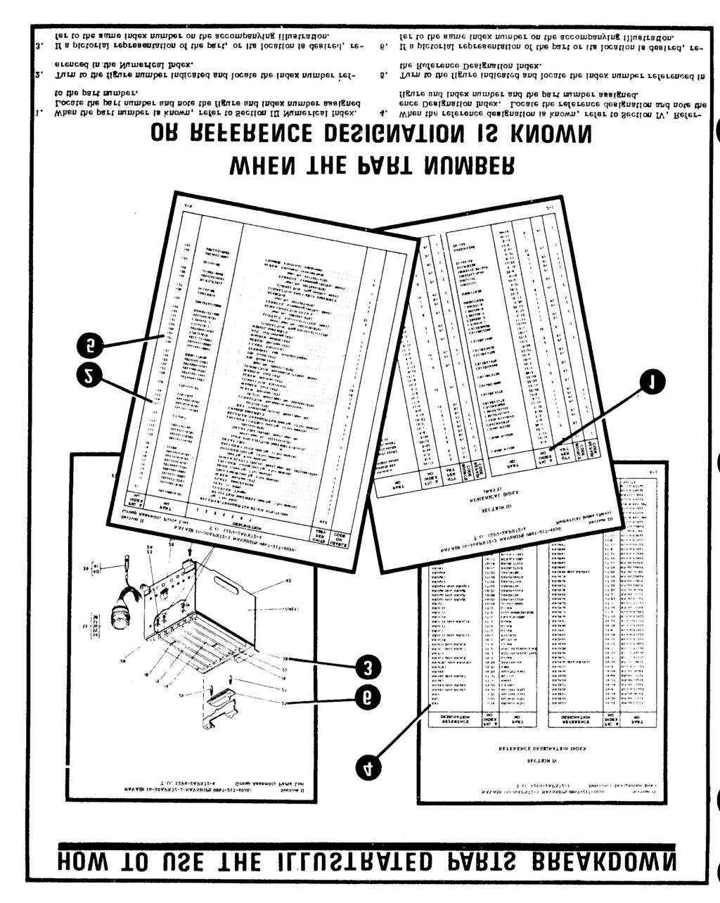
100 6-6
101 SECTION II Figure 6-1. Transponder Set Test Set AN/APM-378 FIGURE UNITS USABLE & INDEX PER ON No. PART NUMBER DESCRIPTION ASSY CODE TEST SET, Transponder Set AN/APM COVER, Test set (see fig. 6-2 for breakdown) TEST SET, Transponder (see fig. 6-3 for breakdown).. 1 AN3C24A BOLT (AP) Ref NAS1598C3Y.. WASHER (AP) Ref MS WASHER (AP) Ref RNF INSULATION, Sleeving (AP) (08795) (06845 spec cont dwg ). Ref GASKET, RF (18565) (06845 spec cont dwg ).. AR -4 D CASE ASSY (19178) (06845 spec cont dwg )
102 Figure 6-2. Test Set Cover 6-8
103 TM &P FIGURE UNITS USABLE & INDEX PER ON NO. PART NUMBER DESCRIPTION ASSY CODE COVER, TEST SET (SEE FIG. 6-1 FOR NHA) REF ANTENNA ASSY BRACKET 1 MS24693C27..SCREW (AP) 3 MS NUT (AP) 3 MS WASHER (AP) 3 MS WASHER (AP) D ANTENNA (82152) (06845 SPEC CONT DWG ) CABLE ASSY, POWER (SEE FIG. 6-4 FOR BREAKDOWN) CABLE ASSY, RF 2 M CONNECTOR 2 RG223U..CABLE, COAXIAL AR CABLE ASSY, RF CONNECTOR, BNC (98291) (06845 SPEC CONT DWG ) 2 RG316U..CABLE, COAXIAL AR MARKER, CABLE CABLE ASSY, SPECIAL PURPOSE CABLE ASSY, POWER (SEE FIG. 6-5 FOR BREAKDOWN) C51.DUMMY CONNECTOR (74868) (06845 SPEC CONT DWG ) INSTRUCTION PLATE DECAL, EQUIPMENT LIST COVER 1 6-9
104 Figure 6-3. FIGURE UNITS USABLE & INDEX PER ON NO. PART NUMBER DESCRIPTION ASSY CODE TEST SET, Transponder (see fig. 6-l for NHA) Ref RF MODULE ASSY (see fig. 6-9 for breakdown) SCREW, Captive (AP) Ref MS RING, Retaining (AP) Ref DECODER MODULE (see fig for breakdown) INTERROGATOR MODULE (see fig for breakdown) SYNCHRONIZER MODULE (see fig for breakdown) EVALUATOR MODULE (see fig for breakdown) CHASSIS ASSY (see fig. 6-8 for breakdown) MS SCREW (AP) : FRONT PANEL ASSY (see fig. 6-6 for breakdown)
105 Figure 6-4. Power Cable Assembly (PN ) FIGURE UNITS USABLE & INDEX PER ON No. PART NUMBER DESCRIPTION ASSY CODE CABLE ASSEMBLY, Power (see fig. 6-2 for NHA) MS3106A14S5S. CONNECTOR UP131M. CONNECTOR MS3057-6A. CLAMP MS BUSHING CO-03LGF3-l.8-. CABLE AR MARKER, Cable MARKER, Cable MARKER, Cable MS LUG, Crimp
106 Figure 6-5. Power Cable Assembly (PN ) FIGURE UNITS USABLE & INDEX PER ON NO. PART NUMBER DESCRIPTION ASSY CODE CABLE ASSEMBLY, Power (see fig. 6-2 for NHA) Ref -1 MS3106A14S5S. CONNECTOR...:::::::: 1-2 MS3107A16-11P. CONNECTOR MS3057-6A. CLAMP MS3057-8A. CLAMP CO-02LLF CABLE AR MARKER, Cable MARKER, Cable MARKER, Cable MS BUSHING l0 MS BUSHING
107 TM &P FIGURE UNITS USABLE & INDEX PER ON NO. PART NUMBER DESCRIPTION ASSU CODE FRONT PANEL ASSY (SEE FIG. 6-3 FOR NHA) REF -1 MS3112E18-32S.CONNECTOR 1-2 MS3102E14S5P.CONNECTOR 1 MS SCREW (AP) 2 MS SCREW (AP) 6 NAS1515H04.ASHER (AP) 8 22NKTM40.NUT, SELF LOCKING (AP) (72962) (06845 SPEC CONT DWG ) CHASSIS, RFI FILTER SHIELD, RFI FILTER COVER, RFI FILTER 1 MS SCREW (AP) 4 MS WASHER (AP) S.GASKET (77820) (06845 SPEC CONT DWG ) S.GASKET (77820) (06845 SPEC CONT DWG ) 1-8 MS C.CAP, CONNECTOR 1-9 MS D.CAP, CONNECTOR CABLE ASSY (SEE FIG. 6-7 FOR BREAKDOWN) 1-11 M CIRCUIT BREAKER 1-12 M CIRCUIT BREAKER BA1BESP.SWITCH, PUSHBUTTON (91812) (06845 SPEC CONT DWG ) 4 MS SCREW (AP) 8-14 MS SWITCH, TOGGLE 1 MS PANEL SEAL (AP) 1-15 MS SWITCH, TOGGLE 1 MS PANEL SEAL (AP) SWITCH, ROTARY 3-17 MS SWITCH, TOGGLE 2 MS PANEL SEAL (AP) 2-18 LH89-1.LAMPHOLDER LAMP (08806) (06845 SPEC CONT DWG ) 2-20 LC35YT2.LENS 1-21 LC35RT2.LENS 1-22 VM300S101.LAMPHOLDER (87034) (06845 SPEC CONT DWG ) 1-23 VM300S102.LAMPHOLDER (87034) (06845 SPEC CONT DWG ) LAMP (08806) (06845 SPEC CONT DWG ) A HANDLE (06540) (06845 SPEC CONT DWG ) 2 NAS 1598C3Y.WASHER (AP) 4 MS SCREW (AP) 4 MS WASHER (AP) 4 MS WASHER (AP)
108 Figure 6-6. Front Panel Assembly 6-14
109 TM &P FIGURE UNITS USABLE & INDEX PER ON NO. PART NUMBER DESCRIPTION ASSY CODE MS K2B.KNOB FILTER, DC (12294) (06845 SPEC CONT DWG ) FILTER, AC (12294) (06845 SPEC CONT DWG ) 2-29 SE26XF03.TERMINAL 2 MS SCREW (AP) 1 MS WASHER (AP) BLOCK, MOUNTING 1 MS SCREW (AP) BLOCK, MOUNTING 1 MS SCREW (AP) SHAFT, THREADED SPACER, SLEEVE LEVER, OPERATING 1 AN565D632H2.SETSCREW (AP) SPACER, THREADED PLATE, IDENTIFICATION PLATE, SERIAL NUMBER PLATE, CAUTION 1-39 MS25281R6.CLAMP, LOOP 1 MS SCREW (AP) 1 MS WASHER (AP) 1 MS WASHER (AP) 1-40 MS25281R3.CLAMP, LOOP 1 MS SCREW (AP) 1 MS WASHER (AP) 1 MS WASHER (AP) 1-41 MS TERMINAL LUG 1 MS SCREW (AP) CABLE ASSY (SEE FIG. 6-7 FOR BREAKDOWN) CABLE ASSY (SEE FIG. 6-7 FOR BREAKDOWN) 1-44 MS STRAP, TIEDOWN WIRING HARNESS 1-46 MS TERMINAL LUG MS STRAP, TIEDOWN AN3C24A.BOLT (AP) 4-49 NAS1598C3Y.WASHER (AP) 4-50 MS WASHER (AP) 4-51 RNF INSULATION, SLEEVING (AP) (08795) (06845 SPEC CONT DWG ) 4-52 RCR07G331JS.RESISTOR 1-53 MS TERMINAL (AP) TERMINAL (AP) (17117) (06845 SPEC CONT DWG ) SCREW (AP) PANEL, FRONT
110 TM AP Figure 6-7. Cable Assembly FIGURE UNITS USABLE & INDEX PER ON NO. PART NUMBER DESCRIPTION ASSY CODE CABLE ASSEMBLY (see fig for NHA) o... Ref A CABLE ASSEMBLY (see fig. 6-6 for NHA)., e....o Ref B CABLE ASSEMBLY (see fig. 6-6 for NHA) c.. Ref C CONNECTOR (95712) (06845 spec cont dwg ) ABC CONNECTOR (98291) (06845 spec cont dwg ) ABC -3 RG316U. CABLE, Coaxial...,... AR ABC MARKER, Cable A MARKER, Cable B 20, MARKER, Cable C 6-16
111 Figure 6-8. Chassis Assembly FIGURE UNITS USABLE & INDEX PER ON NO. PART NUMBER DESCRIPTION ASSY CODE CHASSIS ASSEMBLY (see fig. 6-3 for NHA) Ref PRINTED WIRING BOARD ASSEMBLY MS WASHER (AP) MS WASHER (AP) MS SCREW :. PIN, Locating NCD CONNECTOR (16512) (06845 spec cont dwg )......, 4-4 NCD CONNECTOR (16512) (06845 spec cont dwg ) PRINTED WIRING BOARD PRINTED CIRCUIT CARD ENCLOSURE (ESF) (06845 spec cont dwg )....,.,.. 1 MS SCREW MS : WASHER (AP) MS WASHER (AP) H935 TRANSFORMER, Power, stepdown (80223)(06845 spec cont dwg )
112 TM &P FIGURE UNITS USABLE & INDEX PER ON NO. PART NUMBER DESCRIPTION ASSY CODE 6-8- MS NUT (AP) 4 MS WASHER (AP) 4 MS WASHER (AP) 4-8 MDA952-2.RECTIFIER, SEMICONDUCTOR DEVICE, DIODE, BRIDGE ASSY (04713) (06845 SPEC CONT DWG ) 1 MS SCREW (AP) 2 MS WASHER (AP) 2-9 1N5550.DIODE 1-10 RER70F9R09M.RESISTOR 1 MS SCREW (AP) 2 MS WASHER (AP) 2 MS WASHER (AP) 2 MS NUT (AP) 2-11 RER70F12ROM.RESISTOR 1 MS SCREW (AP) 2 MS WASHER (AP) 2 MS WASHER (AP) 2 MS NUT (AP) 2-12 M CAPACITOR KM.INTEGRATED CIRCUIT, VOLTAGE REGULATOR (07263) (06845 SPEC CONT DWG ) 1 MS SCREW (AP) 2 MS WASHER (AP) 2 MS NUT (AP) KM.INTEGRATED CIRCUIT, VOLTAGE REGULATOR (07263) (06845 SPEC CONT DWG ) 1 MS SCREW (AP) 2 MS WASHER (AP) 2 MS NUT (AP) 2-15 MS LUG, TERMINAL 1 MS SCREW (AP) 1 MS NUT (AP) 1-16 MS25281R3.CLAMP, LOOP 2 MS SCREW (AP) 1 MS WASHER (AP) 1 MS NUT (AP) 1-17 MS25281R6.CLAMP, LOOP 1 MS SCREW (AP) 1 MS WASHER (AP) 1 MS NUT (AP) CHASSIS, ELEC EQUIPMENT PIN, GUIDE 2-20 SL F..TERMINAL STUD, INSULATED (12615) (06845 SPEC CONT DWG )
113 TM &P FIGURE UNITS USABLE & INDEX PER ON NO. PART NUMBER DESCRIPTION ASSY CODE A31..CLIP, SPRING TENSION (99378) (06845 SPEC CONT DWG MS N..RIVET (AP) 2-22 NCN NUT, CAPTIVE (07886) (06845 SPEC CONT DWG ) 4-23 NCN NUT, SELF-LOCKING, CLINCH, FLOATING (07886) (06845 SPEC CONT DWG ) 2-24 NCN NUT, CAPTIVE (07886) (06845 SPEC CONT DWG ) JACK, TIP (98291) ( SPEC CONT DWG ) JACK, TIP (98291) (06845 SPEC CONT DWG ) 2-27 SL F..TERMINAL STUD, INSULATED (12615) (06845 SPEC CONT DWG ) 2-28 MS NUT, CLINCH CHASSIS, ELEC EQUIPMENT
114 Figure 6-9. RF Module Assembly 6-20
115 TM &P FIGURE UNITS USABLE & INDEX PER ON NO. PART NUMBER DESCRIPTION ASSY CODE RF MODULE ASSEMBLY (SEE FIG. 6-3 FOR NHA) REF COVER, PROTECTIVE 1 MS SCREW (AP) 4 MS WASHER (AP) 4 MS WASHER (AP) PRINTED WIRING BOARD 1 MS SCREW (AP) 4 MS WASHER (AP) OSCILLATOR MODULE 1 MS SCREW (AP) 2 MS WASHER (AP) 2 MS WASHER (AP) MICROSTRIP MODULE 1 MS SCREW (AP) 2 MS WASHER (AP) 2 MS WASHER (AP) IF. VIDEO MODULE 1 MS SCREW (AP) 2 MS WASHER (AP) 2 MS WASHER (AP) 2-6 NCD CONNECTOR, PLUG, ELECTRICAL (16512) (06845 SPEC CONT DWG ) 1 MS NUT (AP) 2-7 RCR07G201JS.RESISTOR 1-8 RT22C2X102.RESISTOR 1-9 RT22C2X103.RESISTOR CABLE, COAX SCREW, CAPTIVE 2-12 MS RING, RETAINING HOUSING, RF
116 Figure Module Assemblies FIGURE UNITS USABLE & INDEX PER ON NO. PART NUMBER DESCRIPTION ASSY CODE DECODER MODULE (see fig. 6-3 for NHA) Ref A INTERROGATOR MODULE (see fig. 6-3 for NHA) Ref SYNCHRONIZER MODULE B (see fig. 6-3 for NHA).,.... Ref C EVALUATOR MODULE Ref D S202. EJECTOR (18677) (06845) spec cont dwg ABCD -2 S202. EJECTOR (18677) (06845) spec cont dwg , S202 alter from EJECTOR (18677) (06845) spec A S202 cont dwg , alter from ,. 1. EJECTOR (18677) (06845) spec B S202 cont dwg , alter from EJECTOR (18677) (06845) spec C cont dwg , alter from D 6-22
117 SECTION III TM &P NUMERICAL INDEX FIGURE FIGURE & INDEX & INDEX PART NUMBER NO. CODES PART NUMBER NO. CODES AN3C24A PAGZZ MS PAGZZ AN565D632H2 6-6 XBGZZN MS PAGZZ CO-02LGF MS PAGZZ CO-02LLF D XBGGG MS PAGZZ H PAGZZ LC35RT PAGZZ MS PAGZZ LC35YT PAGZZ MS PAGZZ LH PAGZZ MS PAGZZ MDA PAGZZ 6-9 MS PAGZZ 6-2 PAGZZ MS PAGZZ MS PAGZZ MS PAGZZ MS PAGZZ 6-8 MS PAGZZ MS PAGZZ 6-6 MS PAGZZ MS N 6-8 PAGZZ MS PAGZZ MS PAGZZ MS MS PAGZZ MS PAGZZ MS PAGZZ MS PAGZZ MS PAGZZ MS PAGZZ MS24693C PAGZZ MS PAGZZ MS PAGZZ MS PAGZZ MS PAGZZ MS D XBGZZN MS PAGZZ MS PAGZZ 6-8 MS25281R PAGZZ MS ,6-2A PAGZZ MS PAGZZ MS25281R PAGZZ MS PAGZZ MS PAGZZ MS3057-6A PAGZZ MS PAGZZ MS PAGZZ MS3057-8A PAGZZ MS PAGZZ MS3102E14S5P PAGZZ MS PAGZZ MS3106A14S5S PAGZZ MS PAGZZ MS MS3107A16-11P PAGZZ MS PAGZZ MS3112E18-32S PAGZZ MS K2B PAGZZ MS C XBGZZN MS
118 TM &P FIGURE FIGURE & INDEX & INDEX PART NUMBER NO. CODES PART NUMBER NO. CODES M PAGZZ M PAGZZ XBGGG M PAGZZ MDGZZ NAS1515H PAGZZ MDGZZ NAS1598C3Y PAGZZ MDGZZ NAS1598C MDGZZ NCD PAGZZ NCD PAGZZ MDGZZ NCD PAGZZ MDGZZ NCN PAGZZ MDGZZ NCN XBGZZN MDGZZ NCN PAGZZ RCR07G201JS PAGZZ RCR07G331JS RER70F12ROM PAGZZ RER70F9R09M PAGZZ PAGZZ RG223U PAGZZ RG316U PAGZZ NKTM PAGZZ RNF BA1BESP PAGZZ RT22C2X PAGZZ RT22C2X PAGZZ PAOZZ SE26XF PAGZZ SL F PAGZZ PAOZZ SL F PAGZZ PAGZZ S PAGZZ PAGZZ UP131M PAGZZ VM300S PAGZZ PAGZZ VM300S PAGZZ PAGZZ XBGZZN PAGZZ PAGZZ XBGZZN PAGZZ PAGZZ PAGZZ PAOZZ 1N PAGZZ PAGZZ PAGZZ S PAGZZ PAGZZ S PAGZZ PAGZZ A PAGZZ PAGZZ 10509A PAGZZ PAGZZ PAGZZ PAGZZ 15D PAGZZ XBGGG PAGZZ XBGGG PAGZZ MDGZZ MDGZZ MDGZZ XBGZZN PAGZZ XBGZZN XBGGG PAGZZ XBGGG 6-24
119 TM &P FIGURE FIGURE & INDEX & INDEX PART NUMBER NO. CODES PART NUMBER NO. CODES XBGGD ADGGG AGGGG MDGZZ PAGZZ MDGZZ PAGZZ MDGZZ AGGGG PAGZZ PAGZZ PAGZZ MDGZZ PAGZZ MDGZZ PAGZZ MDGZZ PAGZZ XBGZZ PAGZZ PAGZZ PAGZZ MGGZZ MGGZZ AGGGG MGGZZ AGGGG MGGZZ ADGGG PAGZZ AGGGG MDGZZ MDGZZ XAGZZ MDGZZ MDGZZ MDGZZ MDGZZ 4075C PAGZZ PAGZZ MDGZZ MDGZZ PAOZZ XBGZZ 7805KM PAGZZ PEOGD 7812KM PAGZZ XBGZZN PAGZZ PAGZZ PAGZZ 6-25
120 SECTION IV TM &P REFERENCE DESIGNATION INDEX FIGURE FIGURE REF & INDEX REF & INDEX DES NO. PART NUMBER DES NO. PART NUMBER AT C51 S10-S MS A T H935 A1A NCD U A1R RT22C2X103 U A1R RT22C2X102 U A1R RCR07G201JS U A1U U UGJ A1U U UGJ A1U W CB M W1P UP131M CB M W1P MS3106A14S5S CR MDA952-2 W CR N5550 W2P MS3106A14S5S C M W2P MS3107A16-11P DS1, W DS3, W FL1, W FL2, W J MS3112E18-32S W J MS3102E14S5P W R RER70F9R09M XA NCD R RER70F12ROM XDS1, LH89-1 R RCR07G331JS XDS VM300S101 S1-S BA1BESP XDS VM300S102 S MS XU1,2, NCD S MS ,4 S7-S
121 APPENDIX A REFERENCES The following is a list of applicable references that are available to the operator and repairmen of the Transponder Set Test Set AN/APM-378: AR DA Pam SB SB SB SB SB TB SIG 291 TB TM TM TM Printing, Camouflage Painting, and Marking of Army Materiel. Index of Technical Publications. Availability of Tool Kit, Dial Central Office Maintenance, TK-82/GT. Painting and Preservation of Supplies Available for Field Use for Electronics Command Equip ment. Replacement of Tool Kits, Radar and Radio Repairman, TK-87/U and TK-88/U with Tool Kits, Electronic Equipment, TK-105/G and TK-100/G. Preservation, Packaging, Packing and Marking Materials, Supplies and Equipment Used by The Army. Army Adopted/Other Items Selected for Authorization/ List of Reportable Items. Safety Measures to be Observed When Installing and Using Whip Antennas, Field-Type Masts, Towers and Antennas and Metal Poles That are Used With Communications, Radar and Direction Finder Equipment. Field Instructions for Painting and Preserving Electronics Command Equipment Including Camouflage Pattern Painting of Electrical Equipment Shelters. Organizational Maintenance Manual Receiver-Transmitters, Radio RT-859/APX-72 (NSN ) and RT-859A/APX-72 (NSN ) and Mountings, MT-3809/ APX-72 (NSN ) and MT-3948/APX-72 (NSN ). Operator s and Organizational Maintenance Manual: Transponder Set AN/APX-100(V). Operator s and Organizational Maintenance Manual: Multimeter AN/URM-105 and AN/URM- 105C (Including Multimeter ME-77/U and ME-77C/U. TM TM Operator s Manual: Pulse Generator Sets AN/UPM-15 and AN/UPM-15A. Operator s, Organizational, Direct Support and General Support Maintenance Manual Including Repair Parts and Special Tools Lists: Voltmeter, Digital AN/GSM-64B (NSN ) Including Plug-in Electronic Test Equipment PL-1370/GSM-64B (NSN ). Change 1 A - 1
122 TM TM TM TM TM 1l TM TM Operator s and Organizational Maintenance Manual: Test Sets, Radio Frequency Power AN/USM-161 and AN/USM-161A (NSN ). Operator s, Organizational, Direct Support, and General Support Maintenance Repair Parts and Special Tools List (Including Depot Maintenance Repair Parts and Special Tools List) for Multimeter, AN/USM-223. Operator s Organizational, Direct Support, General Support, and Depot Maintenance Manual: Oscilloscope AN/USM-281A (NSN Operator s and Organizational Maintenance Manual for Test Set, Radar AN/TPM-25A (NSN ). Operator s Organizational, Direct Support, and General Support Maintenance Manual: Counter, Electronic, TD-1225 (V) l/u (NSN ). The Army Maintenance Management System (TAMMS). Procedures for Destruction of Electronics Materiel to Prevent Enemy Use (Electronics Command). A-2 Change 1
123 APPENDIX B COMPONENTS OF END ITEM LIST Section I. INTRODUCTION B-1. Scope This appendix lists integral components of and basic issue items for the AN/APM-378 to help you inventory items required for safe and efficient operation. B-2. General This Components of End Item List is divided into the following sections: a. Section II. Integral Components of the End Item. Not applicable. b. Section III. Basic Issue Items. These are the minimum essential items required to place the AN/APM 378 in operation, to operate it, and to perform emergency repairs. Although shipped separately packed they must accompany the during operation and whenever it is transferred between accountable officers. The illustrations will assist you with hard-to-identify items. This manual is your authority to requisition replacement BII, based on TOE/MTOE authorization of the end item. B-3. Explanation of Columns a. Illustration. This column is divided as folfigure lows : (1) Figure number. Indicates the number of the illustration on which the item is shown. (2) Item number. The number used to identify item called out in the illustration. b. National Stock Number. Indicates the National stock number assigned to the item and which will be used for requisitioning. c. Description. Indicates the Federal item name and, if required, a minimum description to identify the item. The part number indicates the primary number used by the manufacture, which controls the design and characteristics of the item by means of its engineering drawings, specifications, standards, and inspection requirements to identify an item or range of items. Following the part number, the Federal Supply Code for Manufacturers (FSCM) is shown in parentheses, d. Location. The physical location of each item listed is given in this column, The lists are designed to inventory all items in one area of the major item before moving on to an adjacent area. e. Usable on Code. USABLE ON codes are included to help you identify which component items are used on the different models. Identification of the codes used in these lists are: Code Used On f. Quantity Required (Qty Reqd). This column lists the quantity of each item required for a complete major item. g. Quantity. This column is left blank for use, during an inventory. Under the Rcvd column, list the quantity you actually receive on your major item. The Date columns are for your use when you inventory the major item. (Next printed page is B-2.) B-1
124 TM &P SECTION III BASIC ISSUE ITEMS (1) (2) (3) (4) (5) (6) (7) ILLUSTRATION NATIONAL DESCRIPTION LOCATION USABLE QTY QUANTITY (A) (B) STOCK ON REQ'D FIG ITEM NUMBER CODE RCVD DATE NO NO PART NUMBER (FSCM) TEST SET, TRANSPONDER EDY ANTENNA ASSEMBLY EDY CABLE AC POWER EDY CABLE DC POWER EDY SPECIAL PURPOSE CABLE EDY RF CABLE (25 FEET) EDY RF CABLE (6 INCHES) EDY DUMMY CONNECTOR 4075C EDY COVER, TEST SET EDY CASE ASSEMBLY D EDY 1 B-2
125 APPENDIX C ADDITIONAL AUTHORIZATION LIST Section I. INTRODUCTION C-1. Scope This appendix lists additional items you are authorized for the support of the Transponder Set, Test Set AN/APM-378. C-2. General This list identifies items that do not have to accompany the AN/APM 378 and that do not have to be turned in with it. These items are all authorized to you by CTA, MTOE, TDA, or JTA. C-3. Explanation of listing National stock numbers, descriptions, and quantities are provided to help you identify and request the additional items you require to support this equipment. The items are listed in alphabetical sequence by item name under the type document (i.e., CTA, MTOE, TDA, or JTA) which authorizes the item (s) to you. If the item you require differs between serial numbers of the same model, effective serial numbers are shown in the last line of the description. If item required differs for different models of this equipment, the model is shown under the Usable cm heading in the description column. These codes are identified as: Code Used On (Next printed page is C-2.) C-1
126 TM &P SECTION II ADDITIONAL AUTHORIZATION LIST (1) (2) (3) (4) NATIONAL DESCRIPTION UNIT QTY STOCK OF AUTH NUMBER MEAS USABLE ON PART NUMBER AND FSCM CODE IRW DIVERSITY ANTENNA, AS-3324/APM-378 EA 5397 SF C-2
127 APPENDIX D MAINTENANCE ALLOCATION Section I. INTRODUCTION D-1. General This appendix provides a summary of the maintenance operations for AN/APM 378. It authorizes categories of maintenance for specific maintenance functions on repairable items and components and the tools and equipment required to perform each function. This appendix may be used as an aid in planning maintenance operations. D-2. Maintenance Function Maintenance functions will be limited to and defined as follows: a. Inspect. To determine the serviceability of an it-em by comparing its physical, mechanical, and/ or electrical characteristics with established standards through examination. b. Test. To verify serviceability and to detect incipient failure by measuring the mechanical or electrical characteristics of an item and comparing those characteristics with prescribed standards. c. Service. Operations required periodically to keep an item in proper operating condition, i.e., to clean (decontaminate), to preserve to drain, to paint, or to replenish fuel, lubricants, hydraulic fluids, or compressed air supplies. d. Adjust. To maintain, within prescribed limits, by bringing into proper or exact position, or by setting the operating characteristics to the specified parameters. e. Align. To adjust specified variable elements of an item to bring about optimum or desired performance. f. Calibrate. To determine and cause corrections to be made or to be adjusted on instruments or test. measuring and diagnostic equipments used in precision measurement. Consists of comparisons of two instruments, one of which is a certified standard of known accuracy, to detect and adjust any discrepancy in the accuracy of the instrument being compared. g. Install. The act of emplacing, seating, or fixing into position an item, part, module (component or assembly) in a manner to allow the proper functioning of the equipment or system. h. Replace. The act of substituting a serviceable like type part, subassembly, or module (component or assembly) for an unserviceable counterpart. i. Repair. The application of maintenance services (inspect, test, service, adjust, align, calibrate, replace ) or other maintenance actions (welding, grinding, riveting, straightening, facing, remachining, or resurfacing) to restore serviceability to an item by correcting specific damage, fault, malfunction or failure in a part, subassembly, module (component or assembly), end item, or system. j. Overhaul. That maintenance effort (service/ action ) necessary to restore an item to a completely serviceable/operational condition as prescribed by maintenance standards (i.e., DMWR) in appropriate technical publications. Overhaul is normally the highest degree of maintenance performed by the Army. Overhaul does not normally return an item to like new condition. k. Rebuild. Consists of those services/actions necessary for the restoration of unserviceable equipment to a like new condition in accordance with original manufacturing standards. Rebuild is the highest degree of materiel maintenance applied to Army equipment. The rebuild operation includes the act of returning to zero those age measurements (hours, miles, etc. ) considered in classifying Army equipment/components. D-3. Column Entries a. Column 1, Group Number. Column 1 lists group numbers, the purpose of which is to identify components, assemblies, subassemblies, and modules with the next higher assembly, b. Column 2, Component/Assembly. Column 2 contains the noun names of components, assemblies, subassemblies, and modules for which maintenance is authorized. c. Column 3, Maintenance Functions. Column 3 D-1
128 lists the functions to be performed on the item listed in column 2, When items are listed without maintenance functions, it is solely for purpose of having the group numbers in the MAC and RPSTL coincide. d. Column 4, Maintenance Category. Column 4 specifies, by the listing of a work time figure in the appropriate subcolumn (s), the lowest level of maintenance authorized to perform the function listed in column 3. This figure represents the active time required to perform that maintenance function at the indicated category of maintenance. If the number or complexity of the tasks within the listed maintenance function vary at different maintenance categories, appropriate work time figures will be shown for each category. The number of task-hours specified by the work time figure represents the average time required to restore an item (assembly, subassembly, component, module, end item or system) to a serviceable condition under typical field operating conditions. This time includes preparation time, troubleshooting time, and quality assurance/quality control time in addition to the time required to perform the specific tasks identified for the maintenance functions authorized in the maintenance allocation chart. Subcolumns of column 4 are as follows: C Operator/Crew O Organizational F Direct Support H General Support D Depot e. Column 5, Tools and Equipment. Column 5 specifies by code, those common tool sets (not individual tools) and special tools, test, and support equipment required to perform the designated function. j. Column 6, Remarks. Column 6 contains an alphabetic code which leads to the remark section IV, Remarks, which is pertinent to the item opposite the particular code. D 4. Tool and Test Equipment Requirements (Sec. III) a. Tool or Test Equipment Reference Code. The numbers in this column coincide with the numbers used in the tools and equipment column of the MAC. The numbers indicate the applicable tool or test equipment for the maintenance functions. b. Maintenance Category. The codes in this column indicate the maintenance category allocated the tool or test equipment. c. Nomenclature. This column lists the noun name and nomenclature of the tools and test equipment required to perform the maintenance functions. d. National/NATO Stock Number. This column lists the National/NATO stock number of the specific tool or test equipment. e. Tool Number. This column lists the manufacturer s part number of the tool followed by the Federal Supply Code for manufacturers (5-digit) in parentheses. D 5. Remarks (Sec. IV) a. Reference Code. This code refers to the appropriate item in section II, column 6. b. Remarks. This column provides the required explanatory information necessary to clarify items appearing in section II. (Next printed page is D-3.) D-2
129 SECTION II MAINTENANCE ALLOCATION CHART FOR AN/APM-378 TM &P (4) 0) (2) (3) (9) Ml NTENANCE cxte~ry (6) GROCJP CXWWONEFW/ASSEMSLY AM1NTEN4NCE TOOLS REA44RNS NUMBER PUNCTION AND c o F H D EQPT. 00 TRAMSPOMDER SET TEST SET AN/ APM-378 Inspect.1 Test.2 1 A Test , 12 Replace.3 2 Repair 1.0?1 t? Adjust.5 9, RF MODULE ASSY ( ) Inspect Test :; 3-8 Replace.3 11 Repair.5 11 c 02 CHASSIS ASSY ( ) Inspect.1 Test 3 Repair :: 11 D 03 FROMT PANEL ASSY ( ) Inspect.1 Test.2 3 Repair AC POWER CABLE ASSY (WI) ( ) Inspect.1 Test.2 3 Repair BC POWER CABLE ASSY (U2) ( ) Inspect.1 Test.2 3 Repair COVER, TEST SET ( ) Inspect.1 Repair CABLE ASSYa SPECIAL PURPOSE (U3) Inspect.1 ( ) Test.2 3 Repair CABLE ASSY, RF (!44) ( ) Inspect.1 Test.2 3 Repair CABLE ASSY, RF (US) ( ) Inspect.1 Test 3 Repair :; 11 D-3
130 TM &P SECTION III TOOL AND TEST EQUIPMENT REQUIREMENTS FOR AN/APM-378 TOOL OR TEST EQUIPMENT MAINTENANCE NOMENCLATURE NATIONAL/NATO TOOL NUMBER REF CODE CATEGORY STOCK NUMBER 1 0 MULTIMETER AN/URM-105C TOOL KIT, ELECTRONIC EQUIP TK-101/G F MULTIMETER AN/USM F ATTENUATOR, FIXED COAXIAL 6DB (WEINSCHEL 2-6) F VOLTMETER, DIGITAL AN/GSM-64B F COUNTER, ELECTRONIC DIGITAL READOUT TS-1225(V)/U F OSCILLOSCOPE AN/USM-281A F TEST SET, RADIO FREQUENCY POWER AN/USM F RADAR TEST SET AN/TPM-25A F PULSE GENERATOR AN/UPM-15A F TOOL KIT, ELECTRONIC EQUIP TK-105/G F CIRCULATOR M3B-1030 (96341) D-4
131 SECTION IV. REMARKS TM &P REFERENCE CODE REMARKS A B C D OPERATIONAL TEST REPLACE DECODER, INTERROGATOR, SYNCHRONIZER, EVALUATOR MODULES REPLACE TRANSMITTER, MICRO STRIP AND IF VIDEO MODULES REPLACE CHASSIS MOUNTED PARTS. IF TD-1225(V)1/U NOT AVAILABLE USE AN/USM-207A AND CM-77/U D-5
132
133 APPENDIX E REPAIR PARTS LIST Section I. INTRODUCTION E-1. Scope This appendix lists spares and repair parts; special tools, special test, measurement, and diagnostic equipment (TMDE), and other special support equipment required for performance of direct support maintenance of the AN/APM 378. It authorizes the requisitioning and issue of spares and repair parts as indicated by the source and maintenance codes. E-2. General This Repair Parts and Special Tools List is divided into the following sections: a. Sectiom II. Repair Parts List. A list of spares and repair parts authorized for use in the performance of maintenance. The list also includes parts which must be removed for replacement of the authorized parts. b. Section III. Special Tools List. Not applicable. c. Section IV. National Stock Number and Part Number Index. A list, in National item identification number (NIIN) sequence, of all National stock numbers (NSN) appearing in the listings, followed by a list, in alphameric sequence, of all part numbers appearing in the listings. National stock numbers and part number are cross-referenced to each illustration figure and item number appearance. E 3. Explanation of Columns a. Illustration. This column is divided as follows : (1) Figure number. Indicates the figure number of the illustration on which the item is shown. (2) Item number. The number used to identify item called out in the illustration. b. Source, Maintenance, and Recwerabilitv (SMR) Codes. (1) Source code. Source codes indicate the manner, of acquiring support items for maintenance, repair, or overhaul of end item, Source codes are entered in the first and second positions of the Uniform SMR Code format as follows: Code Definition PA Item procured and stocked for anticipated or known usage. XD A support item that is not stocked. When required, item will be procured through normal supply channels. NOTE Cannibalization or salvage may be used as a source of supply for any items source coded above except those coded XA and aircraft support items as restricted by AR (2) Maintenance code. Maintenance codes are assigned to indicate the levels of maintenance authorized to USE and REPAIR support items. The maintenance codes are entered in the third and fourth positions of the Uniform SMR Code format as follows: (a) The maintenance code entered in the third position will indicate the lowest maintenance level authorized to remove, replace, and use the support item. The maintenance code entered in the third position will indicate one of the following levels of maintenance: Code Application./Explanation F Support item is removed, replaced, used at the direct support level. (b) The maintenance code entered in the fourth position indicates whether the item is to be repaired and identifies the lowest maintenance level with the capability to perform complete repair (i.e., all authorized maintenance functions). This position will contain one of the following maintenance codes: Code Application/Explanation F The lowest maintenance level capable of complete repair of the support item is the direct support level. Z Nonreparable. No repair is authorized. E-1
134 (3) Recoverability code. Recoverability codes are assigned to support items to indicate the disposition action on unserviceable items. The recoverability code is entered in the fifth position of the Uniform SMR Code format as follows: Recoverability codes Definition Z Nonreparable item. When unserviceable, condemn and dispose at the level indicated in position 3. F Reparable item. When uneconomically reparable, condemn and dispose at the direct support level. A Item requires special handling or condemnation procedures because of specific reasons (i.e., precious metal content, high dollar value, critical material or hazardous material). Refer to appropriate manuals/directives for specific instructions. c. National Stock Number. Indicates the National stock number assigned to the item and will be used for requisitioning purposes. d. Part Number. Indicates the primary number used by the manufacturer (individual, company, firm, corporation, or Government activity), which controls the design and characteristics of the item by means of its engineering drawings, specifications, standards, and inspection requirements to identify an item or range of items. NOTE When a stock numbered item is requisitioned, the repair part received may have a different part number than the part being replaced. e. Federal Supply Code for Manufacturer (FSCM). The FSCM is a 5-digit numeric code listed in SB which is used to identify the manufacturer, distributor, or Government agency, etc. f. Description. Indicates the Federal item name and, if required, a minimum description to identify the item. g. Unit of Measure (U/M). Indicates the standard of the basic quantity of the listed item as used in performing the actual maintenance function. This measure is expressed by a two-character alphabetical abbreviation (e.g., ea r in pr, etc.). When the unit of measure differs from the unit of issue, the lowest unit of issue that will satisfy the required units of measure will be requisitioned. h. Quantity Incorporated in Unit. Indicates the quantity of the item used in the equipment. E-4. Special Information National stock numbers (NSN s) that are miss ing from P source coded items have been applied for and will be added to this TM by future change revision when they are entered in the Army Master Data File (AMDF). Until the NSN s are established and published, submit exception requisitions to: Commander, US Army Communications and Electronics Materiel Readiness Command, ATTN: DRSEL MM, Fort Monmouth, NJ for the part required to support your equipment. E 5. How to Locate Repair Parts a. When National stock number or part number is unknown. (1) First. Find the illustration covering the functional group to which the item belongs. (2) Second. Identify the item on the illustration and note the illustration figure and item number of the item. (3) Third. Using the Repair Parts Listing find the figure and item number noted on the illustration. b. When National stock number or part number is known. (1) First. Using the Index of National Stock Numbers and Part Numbers, find the pertinent National stock number or part number. This index is in NIIN sequence followed by a list of part numbers in alphameric sequence, cross-referenced to the illustration figure number and item number. (2) Second. After finding the figure and item number, locate the figure and item number in the repair parts list. E 6. Abbreviations Not applicable. (Next printed page is E-5.) E-2
135 SECTION II TM &P (1) (2) (3) (4) (5) (6) (7) (8) ILLUSTRATION QTY (A) (B) NATIONAL DESCRIPTION INC FIG ITEM SMR STOCK PART IN NO NO CODE NUMBER NUMBER FSCM USABLE ON CODE U/M UNIT TRANSPONDER SET AN/APM XDFFF COVER,TEST SET EA XDFFF TEST SET TRANSP EA A PAFZZ AN3C24A BOLT,MACHINE EA B PAFZZ NAS1598C3Y PACKING WITH RETAIN EA C PAFZZ MS WASHER,FLAT EA D XDFZZ RNF INSULATION EA XDFZZ GASKET, RF EA XDFZZ D CASE ASSY EA XDFFF ANTENNA ASSEMBLY EA XDFZZ BRACKET EA A PAFZZ MS24693C SCREW,MACHINE EA B PAFZZ MS NUT,PLAIN,HEXAGON EA C PAFZZ MS WASHER,LOCK EA D PAFZZ MS WASHER,FLAT EA PAFZZ ANTENNA EA XDFFF CABLE ASSEMBLY EA XDFFF CABLE ASSY,RF EA A PAFZZ M CONNECTOR,PLUG,ELEC EA B PAFZZ RG223U CABLE,RADIO FREQUEN EA XDFFF CABLE ASSY,RF EA A PAFZZ CONNECTOR,PLUG,ELEC EA B PAFZZ RG316U CABLE,RADIO FREQUEN EA C XDFZZ MARKER,CABLE EA PAFZZ CABLE ASSEMBLY,SPEC EA XDFFF CABLE ASSY PWR EA PAFZZ 4075C DUMMY CONNECTOR EA XDFZZ INSTRUCTION PLATE EA XDFZZ DECAL EQUIP LIST EA XDFZZ COVER EA PAFFA MODULE ASSEMBLY EA A PAFZZ SCREW,CAPTIVE EA B PAFZZ MS RING,RETAINING EA PAFZZ DECODER,PULSE EA PAFZZ INTERROGATOR EA PAFZZ SYNCHRONIZER,ELECTR EA PAFZZ EVALUATOR EA XDFFF CHASSIS ASSY EA A PAFZZ MS SCREW,MACHINE EA XDFFF FRONT PANEL ASSY EA 1 E-5
136 SECTION II TM &P (1) (2) (3) (4) (5) (6) (7) (8) ILLUSTRATION QTY (A) (B) NATIONAL DESCRIPTION INC FIG ITEM SMR STOCK PART IN NO NO CODE NUMBER NUMBER FSCM USABLE ON CODE U/M UNIT PAFZZ MS3106A14S5S CONNECTOR,PLUG,ELEC EA PAFZZ UP131M CONNECTOR,PLUG,ELEC EA PAFZZ MS3057-6A ADAPTER,CABLE CLAMP EA XDFZZ MS BUSHING,RUBBER EA XDFZZ C0-03LGF CABLE EA XDFZZ MARKER,CABLE EA XDFZZ MARKER,CABLE EA XDFZZ MARKER,CABLE EA XDFZZ MS TERMINAL,LUG EA PAFZZ MS3106A14S5S CONNECTOR,PLUG,ELEC EA PAFZZ MS3107A16-11P CONNECTOR,PLUG,ELEC EA PAFZZ MS3057-6A ADAPTER,CABLE CLAMP EA PAFZZ MS3057-8A CLAMP,CABLE,ELECTRI EA XDFZZ CO-02LLF CABLE EA XDFZZ MARKER,CABLE EA XDFZZ MARKER,CABLE EA XDFZZ MARKER,CABLE EA XDFZZ MS BUSHING,RUBBER EA XDFZZ MS BUSHING,ELECTRICAL EA PAFZZ MS3112E18-32S CONNECTOR,RECEPTACL EA PAFZZ MS3102E14S5P CONNECTOR,RECEPTACL EA A PAFZZ MS SCREW,MACHINE EA B PAFZZ MS SCREW,MACHINE EA C PAFZZ NAS1515H INSULATOR,WASHER EA D PAFZZ NKTM NUT,SELF-LOCKING,CA EA XDFZZ CHASSIS,RFI,FILTER EA XDFZZ SHIELD,RFI,FILTER EA XDFZZ COVER,RFI,FILTER EA 6-6 5A PAFZZ MS SCREW,MACHINE EA B PAFZZ MS WASHER,FLAT EA XDFZZ S GASKET EA XDFZZ S GASKET EA PAFZZ MS C CONNECTOR EA PAFZZ MS D COVER,ELECTRICAL CO EA XDFFF CABLE ASSY EA PAFZZ M CIRCUIT BREAKER EA PAFZZ M CIRCUIT BREAKER EA PAFZZ 2808BA1BESP SWITCH PUSHBUTTON EA A PAFZZ MS SCREW,MACHINE EA PAFZZ MS SWITCH,TOGGLE EA 1 E-6
137 SECTION II TM &P (1) (2) (3) (4) (5) (6) (7) (8) ILLUSTRATION QTY (A) (B) NATIONAL DESCRIPTION INC FIG ITEM SMR STOCK PART IN NO NO CODE NUMBER NUMBER FSCM USABLE ON CODE U/M UNIT A PAFZZ MS PACKING WITH RETAIN EA PAFZZ MS SWITCH,TOGGLE EA A PAFZZ MS PACKING WITH RETAIN EA PAFZZ SWITCH ROTARY EA AFZZ MS SWITCH,TOGGLE EA A PAFZZ MS PACKING WITH RETAIN EA PAFZZ LH LIGHT,INDICATOR EA PAFZZ LAMP,INCANDESCENT EA PAFZZ LC35YT LENS,LIGHT EA PAFZZ LC35RT LENS,LIGHT EA PAFZZ VM300S LAMPHOLDER EA PAFZZ VM300S LAMPHOLDER EA PAFZZ LAMP,INCANDESCENT EA XDFZZ 10509A HANDLE EA A PAFZZ NAS1598C3Y PACKING WITH RETAIN EA B PAFZZ MS SCREW,MACHINE EA C PAFZZ MS WASHER,FLAT EA D PAFZZ MS WASHER,LOCK EA PAFZZ MS K2B KNOB EA PAFZZ FILTER EA PAFZZ FILTER,RADIO FREQUE EA PAFZZ SE26XF TERMINAL,STUD EA A PAFZZ MS SCREW,MACHINE EA B PAFZZ MS WASHER,LOCK EA XDFZZ BLOCK MOUNTING EA A PAFZZ MS SCREW PAN HEAD EA XDFZZ BLOCK,MOUNTING EA A PAFZZ MS SCREW PAN HEAD EA XDFZZ SHAFT EA XDFZZ SPACER SLEEVE EA XDFZZ LEVER OPERATING EA A PAFZZ AN565D632H SETSCREW EA XDFZZ SPACER THREADED EA XDFZZ PLATE ID EA XDFZZ PLATE SERIAL NO EA XDFZZ PLATE CAUTION EA PAFZZ MS25281R CLAMP,LOOP EA A PAFZZ MS SCREW,MACHINE EA B PAFZZ MS WASHER,FLAT EA C PAFZZ MS WASHER,LOCK EA 1 E-7
138 SECTION II TM &P (1) (2) (3) (4) (5) (6) (7) (8) ILLUSTRATION QTY (A) (B) NATIONAL DESCRIPTION INC FIG ITEM SMR STOCK PART IN NO NO CODE NUMBER NUMBER FSCM USABLE ON CODE U/M UNIT PAFZZ MS25281R CLAMP,LOOP EA A PAFZZ MS SCREW,MACHINE EA B PAFZZ MS WASHER,FLAT EA C PAFZZ MS WASHER,LOCK EA PAFZZ MS TERMINAL,LUG EA A PAFZZ MS SCREW,MACHINE EA XDFFF CABLE ASSY EA XDFFF CABLE ASSY EA XDFZZ MS STRAP,TIEDOWN,ELECT EA XDFZZ WIRING HARNESS EA PAFZZ MS TERMINAL,LUG EA PAFZZ MS STRAP,TIEDOWN,ELECT EA PAFZZ AN3C24A BOLT,MACHINE EA PAFZZ NAS1598C3Y PACKING WITH RETAIN EA PAFZZ MS WASHER,FLAT EA XDFZZ RNF INSULATION SLEEVING EA PAFZZ RCR07G331JS RESISTOR,FIXED,COMP EA PAFZZ MS TERMINAL,LUG EA XDFZZ TERMINAL EA XDFZZ SCREW EA XDFZZ PANEL FRONT EA PAFZZ CONNECTION,RECEPTACL EA PAFZZ CONNECTOR,PLUG,ELEC EA XDFZZ RG316U CABLE,RADIO FREQUEN EA XDFZZ MARKER,CABLE USED ON P/N EA A XDFZZ MARKER USED ON P/N EA 6-7 4B XDFZZ MARKER CABLE USED ON P/N EA XDFZZ PRINTED WIRING BD EA 6-8 1A PAFZZ MS WASHER,LOCK EA B PAFZZ MS WASHER,FLAT EA C PAFZZ MS SCREW,MACHINE EA XDFZZ PIN EA PAFZZ CONNECTOR,RECEPTACL EA PAFZZ NCD CONNECTOR,RECEPTACL EA XDFZZ PRINTED WIRING BD EA XDFZZ PRINTED CIRCUIT CD EA A PAFZZ MS SCREW,MACHINE EA B PAFZZ MS WASHER,LOCK EA C PAFZZ MS WASHER,FLAT EA PAFZZ H TRANSFORMER,POWER EA 1 E-8
139 SECTION II TM &P (1) (2) (3) (4) (5) (6) (7) (8) ILLUSTRATION QTY (A) (B) NATIONAL DESCRIPTION INC FIG ITEM SMR STOCK PART IN NO NO CODE NUMBER NUMBER FSCM USABLE ON CODE U/M UNIT 6-8 7A PAFZZ MS NUT,PLAIN,HEXAGON EA B PAFZZ MS WASHER,LOCK EA C PAFZZ MS WASHER,FLAT EA PAFZZ MDA RECTIFIER,SEMICONDU EA A PAFZZ MS SCREW,MACHINE EA B PAFZZ MS WASHER,LOCK EA PAFZZ 1N SEMICONDUCTOR DEVIC EA PAFZZ RER70F9R09R RESISTOR,FIXED,WIRE EA A PAFZZ MS SCREW,MACHINE EA B PAFZZ MS WASHER,FLAT EA C PAFZZ MS WASHER,LOCK EA D PAFZZ MS NUT,PLAIN,HEXAGON EA PAFZZ RER70F12R0M RESISTOR EA A PAFZZ MS SCREW,MACHINE EA B PAFZZ MS WASHER,FLAT EA C PAFZZ MS WASHER,LOCK EA D PAFZZ MS NUT,PLAIN,HEXAGON EA PAFZZ M CAPACITOR EA PAFZZ KM MICROCIRCUIT,LINEAR EA A PAFZZ MS SCREW,MACHINE EA B PAFZZ MS WASHER,LOCK EA C PAFZZ MS NUT,PLAIN,HEXAGON EA PAFZZ 7805KM MICROCIRCUIT,ELECTR EA A PAFZZ MS SCREW,MACHINE EA B PAFZZ MS WASHER,LOCK EA C PAFZZ MS NUT,PLAIN,HEXAGON EA PAFZZ MS TERMINAL,LUG EA A PAFZZ MS SCREW,MACHINE EA B PAFZZ MS NUT,PLAIN,HEXAGON EA PAFZZ MS2521R CLAMP EA A PAFZZ MS SCREW,MACHINE EA B PAFZZ MS WASHER,LOCK EA C PAFZZ MS NUT,PLAIN,HEXAGON EA PAFZZ MS25281R CLAMP,LOOP EA A PAFZZ MS SCREW,MACHINE EA B PAFZZ MS WASHER,LOCK EA C PAFZZ MS NUT,PLAIN,HEXAGON EA XDFFF CHASSIS EA XDFZZ PIN EA XDFZZ SL F TERMINAL,STUD EA 2 E-9
140 SECTION II TM &P (1) (2) (3) (4) (5) (6) (7) (8) ILLUSTRATION QTY (A) (B) NATIONAL DESCRIPTION INC FIG ITEM SMR STOCK PART IN NO NO CODE NUMBER NUMBER FSCM USABLE ON CODE U/M UNIT XDFZZ A CLIP EA A XDFZZ MS N RIVET,TUBULAR EA XDFZZ NCN NUT EA XDFZZ NCN NUT EA XDFZZ NCN NUT,PLAIN,CLINCH EA XDFZZ JACK EA XDFZZ JACK EA XDFZZ S F TERMINAL,STUD EA XDFZZ MS NUT,PLAIN,CLINCH EA XDFZZ CHASSIS EA XDFZZ COVER,PROTECTIVE EA A PAFZZ MS SCREW,MACHINE EA B PAFZZ MS WASHER,LOCK EA C PAFZZ MS WASHER,FLAT EA XDFZZ PRINTED WIRING BD EA A PAFZZ MS SCREW,MACHINE EA B PAFZZ MS WASHER,FLAT EA PAFZZ CIRCUIT CARD ASSEMB EA A PAFZZ MS SCREW,MACHINE EA B PAFZZ MS WASHER,LOCK EA C PAFZZ MS WASHER,FLAT EA PAFZZ MICROSTRIP MODULE EA A PAFZZ MS SCREW,MACHINE EA B PAFZZ MS WASHER,LOCK EA C PAFZZ MS WASHER,FLAT EA PAFZZ CIRCUIT CARD ASSEMB EA A PAFZZ MS SCREW,MACHINE EA B PAFZZ MS WASHER,LOCK EA C PAFZZ MS WASHER,FLAT EA PAFZZ NCD CONNECTOR,RECEPTACL EA A PAFZZ MS NUT,PLAIN,HEXAGON EA PAFZZ RCR07G201JS RESISTOR,FIXED,COMP EA PAFZZ RT22C2X RESISTOR,VARIABLE,W EA PAFZZ RT22C2X RESISTOR,VARIABLE,W EA XDFZZ CABLE,COAX EA PAFZZ SCREW,CAPTIVE EA PAFZZ MS RING,RETAINING EA XDFZZ HOUSING RF EA PAFZZ S EJECTOR,PRINTED CIR EA XDFZZ EJECTOR,PRINTED CIR USED ON P/N EA 1 E-10
141 SECTION II TM &P (1) (2) (3) (4) (5) (6) (7) (8) ILLUSTRATION QTY (A) (B) NATIONAL DESCRIPTION INC FIG ITEM SMR STOCK PART IN NO NO CODE NUMBER NUMBER FSCM USABLE ON CODE U/M UNIT A XDFZZ EJECTOR,PRINTED CIR USED ON P/N EA B XDFZZ EJECTOR,PRINTED CIR USED ON P/N EA C XDFZZ EJECTOR,PRINTED CIR USED ON P/N EA 1 E-11
142 SECTION IV NATIONAL STOCK NUMBER AND PART NUMBER INDEX TM &P FIGURE ITEM FIGURE ITEM STOCK NUMBER NO NO STOCK NUMBER NO NO A A B A B A B A C A B A C B C A C A A A A A A C A A A A A A A A A A A A B A D B A C C C C C B B A B C C B B B A B B B B C C B B B B C C B B D B A D A D A C C B A B C C B B B A D A E-12
143 SECTION IV NATIONAL STOCK NUMBER AND PART NUMBER INDEX TM &P PART FIG ITEM PART FIG ITEM NUMBER FSCM NO NO NUMBER FSCM NO NO AN3C24A A MS B AN3C24A MS D AN565D632H A MS D CO-02LLF MS B C0-03LGF MS A D MS C H MS C LC35RT MS B LC35YT MS C LH MS C MDA MS A MS B MS A MS B MS A MS B MS A MS C MS A MS B MS A MS C MS A MS C MS A MS C MS B MS D MS A MS B MS A MS C MS A MS B MS A MS B MS C MS C MS A MS C MS A MS MS A MS C MS A MS N A MS A MS B MS A MS MS A MS MS A MS MS A MS MS A MS24693C A MS B MS MS A MS MS MS D MS MS A MS MS A MS K2B MS A M A MS2521R M MS25281R M MS25281R M MS25281R NAS1515H C MS3057-6A NAS1598C3Y B MS3057-6A NAS1598C3Y A MS3057-8A NAS1598C3Y MS3102E14S5P NCD MS3106A14S5S NCD MS3106A14S5S NCN MS3107A16-11P NCN MS3112E18-32S NCN MS C RCR07G201JS MS A RCR07G331JS MS A RER70F12R0M MS RER70F9R09R MS RG223U B MS RG316U B MS RG316U MS RNF D MS RNF MS B RT22C2X MS B RT22C2X MS B SE26XF MS C SL F MS C S MS B S F MS B UP131M MS B VM300S MS B VM300S MS C MS B MS A 1N MS B MS C S MS C S MS B A MS B 10509A MS D E-13
144 SECTION IV NATIONAL STOCK NUMBER AND PART NUMBER INDEX TM &P PART FIG ITEM PART FIG ITEM NUMBER FSCM NO NO NUMBER FSCM NO NO 15D A B C C A A B NKTM D BA1BESP C A KM KM E-14
145 APPENDIX F EXPENDABLE SUPPLIES AND MATERIALS LIST Section I. INTRODUCTION F-1. Scope This appendix lists expendable supplies and materials you will need to operate and maintain the Transponder Set, Test Set AN/APM-378. These items are authorized to you by CTA , Expendable Items (Except Medical, Class V, Repair Parts, and Heraldic Items). F-2. Explanation of Columns a. Column 1 Item number. This number is assigned to the entry in the listing and is referenced in the narrative instructions to identify the material (e.g., Use cleaning compound, item 5, App. D ). b. Column 2-Level. This column identifies the lowest level of maintenance that requires the listed item. C Operator/Crew O-Organizational Maintenance/Aviation Unit Maintenance F Direct Support Maintenance/Aviation Intermediate Maintenance H General Support Maintenance c. Column 3 National Stock Number. This is the National stock number assigned to the item; use it to request or requisition the item. d. Column 4 Description. Indicates the Federal item name and, if required, a description to identify the item. The last line for each item indicates the Federal Supply Code for Manufacturer (FSCM) in parentheses followed by a part number. e. Column 5 Unit of Measure (U/M). Indicates the measure used in perfuming the actual maintenance function. This measure is expressed by a two-character alphabetical abbreviation (e.g., ea, in, pr). If the unit of measure differs from the unit of issue, requisition the lowest unit of issue that will satisfy your requirements. (Next printed page is F-2.) F-1
146 SECTION II EXPENDABLE SUPPLIES AND MATERIALS LIST (1) TEM NO. (2).EVEL (3) NATIONAL STOCK NUMBER (4) DESCRIPTION (5) unit OF WEAS PART NO, AND FSCM 3 0 B RI CHLOROTRIFLUOROETHANE 6 OZ. F - 2
147 By Order of the Secretary of the Army: Official: E. C. MEYER General, United States Army Chief of Staff J. C. PENNINGTON Major General, United States Army The Adjutant General DISTRIBUTION : ACTIVE ARMY, USAR, ARNG: To be distributed in accordance with DA Form 12-36A, Organizational Maintenance requirements for AN/APM-123. *us. GOWRNMENT PIUNmNC ofmx: w w41973
148
149
150 TM &P Figure 2-3. Change 1
151 Figure 3-1. Test Set, General Trouble Analysis Diagram (Sheet 2 of 2 )
152 TM &P Figure 3-1.
153 Figure 3-2. RF Section, Trouble Analysis Diagram
154 Figure 3-9. Transponder Set, Test Set AN/APM-378, Front Panel Schematic Diagram. Change 1
155
156 PIN :

157 This fine document... Was brought to you by me: Liberated Manuals -- free army and government manuals Why do I do it? I am tired of sleazy CD-ROM sellers, who take publicly available information, slap watermarks and other junk on it, and sell it. Those masters of search engine manipulation make sure that their sites that sell free information, come up first in search engines. They did not create it... They did not even scan it... Why should they get your money? Why are not letting you give those free manuals to your friends? I am setting this document FREE. This document was made by the US Government and is NOT protected by Copyright. Feel free to share, republish, sell and so on. I am not asking you for donations, fees or handouts. If you can, please provide a link to liberatedmanuals.com, so that free manuals come up first in search engines: <A HREF= Military and Government Manuals</A> Sincerely Igor Chudov Chicago Machinery Movers
TECHNICAL MANUAL OPERATOR S, ORGANIZATIONAL, DIRECT SUPPORT, AND GENERAL SUPPORT MAINTENANCE MANUAL TEST SET, RADIO AN/GRM-114 (NSN )
") TECHNICAL MANUAL OPERATOR S, ORGANIZATIONAL, DIRECT SUPPORT, AND GENERAL SUPPORT MAINTENANCE MANUAL TEST SET, RADIO AN/GRM-114 (NSN 6625-008-6206) HEADQUARTERS, DEPARTMENT OF THE ARMY JUNE 1982 This manual
TECHNICAL MANUAL OPERATOR S, ORGANIZATIONAL, DIRECT SUPPORT, AND GENERAL SUPPORT MAINTENANCE MANUAL TEST SET, RADIO AN/GRM-114 (NSN 6625-008-6206) HEADQUARTERS, DEPARTMENT OF THE ARMY JUNE 1982 This manual
TECHNICAL MANUAL OPERATOR AND ORGANIZATIONAL MAINTENANCE MANUAL MEASURING SET, STANDING WAVE RATIO AN/USM-37E (NSN )
") TECHNICAL MANUAL OPERATOR AND ORGANIZATIONAL MAINTENANCE MANUAL MEASURING SET, STANDING WAVE RATIO AN/USM-37E (NSN 6625-00-197-6910) H E A D Q U A R T E R S, D E P A R T M E N T O F T H E A R M Y FEBRUARY
TECHNICAL MANUAL OPERATOR AND ORGANIZATIONAL MAINTENANCE MANUAL MEASURING SET, STANDING WAVE RATIO AN/USM-37E (NSN 6625-00-197-6910) H E A D Q U A R T E R S, D E P A R T M E N T O F T H E A R M Y FEBRUARY
TM POWER AMPLIFIER AM-6545A/GRC-193A (NSN )
") TECHNICAL MANUAL GENERAL SUPPORT MAINTENANCE MANUAL POWER AMPLIFIER AM-6545A/GRC-193A (NSN 5820-01-186-3699) HEADQUARTERS, DEPARTMENT OF THE ARMY 15 JANUARY 1986 \ Technical Manual No. 11-5820-921-40-2
TECHNICAL MANUAL GENERAL SUPPORT MAINTENANCE MANUAL POWER AMPLIFIER AM-6545A/GRC-193A (NSN 5820-01-186-3699) HEADQUARTERS, DEPARTMENT OF THE ARMY 15 JANUARY 1986 \ Technical Manual No. 11-5820-921-40-2
TECHNICAL MANUAL OPERATOR'S, ORGANIZATIONAL, DIRECT SUPPORT, AND GENERAL SUPPORT MAINTENANCE MANUAL (INCLUDING REPAIR PARTS AND SPECIAL TOOLS LIST)
") TM 11-6625-2781-14&P-5 TECHNICAL MANUAL OPERATOR'S, ORGANIZATIONAL, DIRECT SUPPORT, AND GENERAL SUPPORT MAINTENANCE MANUAL (INCLUDING REPAIR PARTS AND SPECIAL TOOLS LIST) FOR PLUG-IN, LOW FREQUENCY (SPECTRUM
TM 11-6625-2781-14&P-5 TECHNICAL MANUAL OPERATOR'S, ORGANIZATIONAL, DIRECT SUPPORT, AND GENERAL SUPPORT MAINTENANCE MANUAL (INCLUDING REPAIR PARTS AND SPECIAL TOOLS LIST) FOR PLUG-IN, LOW FREQUENCY (SPECTRUM
VOLTMETER, DIGITAL AN/GSM-64C (NSN )
") TECHNICAL MANUAL OPERATOR S, ORGANIZATIONAL DIRECT SUPPORT, AND GENERAL SUPPORT MAINTENANCE MANUAL VOLTMETER, DIGITAL AN/GSM-64C (NSN6625-024-0834) HEADQUARTERS, DEPARTMENT OF THE ARMY 11 MARCH 1983 Technical
TECHNICAL MANUAL OPERATOR S, ORGANIZATIONAL DIRECT SUPPORT, AND GENERAL SUPPORT MAINTENANCE MANUAL VOLTMETER, DIGITAL AN/GSM-64C (NSN6625-024-0834) HEADQUARTERS, DEPARTMENT OF THE ARMY 11 MARCH 1983 Technical
TEST SET TRANSPONDER SET AN/APM - 305A (NSN )
") TM 11 6625-2611-40 TECHNICAL MANUAL DIRECT AND GENERAL SUPPORT MAINTENANCE MANUAL FOR TEST SET TRANSPONDER SET AN/APM - 305A (NSN 6625-01-052-3881) HEADQUARTERS, DEPARTMENT OF THE ARMY OCTOBER 1978 TM
TM 11 6625-2611-40 TECHNICAL MANUAL DIRECT AND GENERAL SUPPORT MAINTENANCE MANUAL FOR TEST SET TRANSPONDER SET AN/APM - 305A (NSN 6625-01-052-3881) HEADQUARTERS, DEPARTMENT OF THE ARMY OCTOBER 1978 TM
TECHNICAL MANUAL DIRECT SUPPORT, GENERAL SUPPORT, AND DEPOT MAINTENANCE MANUAL RADIO SET AN/GRC-144 (NSN )
") TECHNICAL MANUAL DIRECT SUPPORT, GENERAL SUPPORT, AND DEPOT MAINTENANCE MANUAL RADIO SET AN/GRC-144 (NSN 5820-00-926-7356) This copy is a reprint which includes current pages from Changes 1 through 5.
TECHNICAL MANUAL DIRECT SUPPORT, GENERAL SUPPORT, AND DEPOT MAINTENANCE MANUAL RADIO SET AN/GRC-144 (NSN 5820-00-926-7356) This copy is a reprint which includes current pages from Changes 1 through 5.
TECHNICAL MANUAL OPERATOR S, ORGANIZATIONAL, DIRECT SUPPORT, AND GENERAL SUPPORT MAINTENANCE MANUAL INCLUDING REPAIR PARTS AND SPECIAL TOOLS LISTS
 TM 11-6625-2759-14 & P TECHNICAL MANUAL OPERATOR S, ORGANIZATIONAL, DIRECT SUPPORT, AND GENERAL SUPPORT MAINTENANCE MANUAL INCLUDING REPAIR PARTS AND SPECIAL TOOLS LISTS SPECTRUM ANALYZER PL-1391/U (TEKTRONIX
RADIO SET AN/PRC-104(A) (NSN )
 (NSN )") TECHNICAL MANUAL GENERAL SUPPORT MAINTENANCE MANUAL RADIO SET AN/PRC-104(A) (NSN 5820-01-141-7953) HEADQUARTERS, DEPARTMENT OF THE ARMY 15 JANUARY 1986 Technical Manual No. 11-5820-919-40-1 HEADQUARTERS
TECHNICAL MANUAL GENERAL SUPPORT MAINTENANCE MANUAL RADIO SET AN/PRC-104(A) (NSN 5820-01-141-7953) HEADQUARTERS, DEPARTMENT OF THE ARMY 15 JANUARY 1986 Technical Manual No. 11-5820-919-40-1 HEADQUARTERS
DEPARTMENT OF THE ARMY TECHNICAL MANUAL
 DEPARTMENT OF THE ARMY TECHNICAL MANUAL OPERATOR, ORGANIZATIONAL DS, GS, AND DEPOT MAINTENANCE MANUAL OSCILLOSCOPE AN/USM-182A This copy is a reprint which includes current pages from Change 1. HEADQUARTERS,
TECHNICAL MANUAL OPERATOR S ORGANIZATIONAL, DIRECT SUPPORT, AND GENERAL SUPPORT MAINTENANCE MANUAL INCLUDING REPAIR PARTS AND SPECIAL TOOLS LIST FOR
 ARMY TM 11-6625-2827-14&P AIR FORCE TO 33A1-4-67-1 TECHNICAL MANUAL OPERATOR S ORGANIZATIONAL, DIRECT SUPPORT, AND GENERAL SUPPORT MAINTENANCE MANUAL INCLUDING REPAIR PARTS AND SPECIAL TOOLS LIST FOR ELECTROMAGNETIC
TECHNICAL MANUAL DIRECT SUPPORT, GENERAL SUPPORT, AND DEPOT MAINTENANCE MANUAL INCLUDING REPAIR PARTS AND SPECIAL TOOLS LISTS RADIO SET AN/PRC-47
 TECHNICAL MANUAL DIRECT SUPPORT, GENERAL SUPPORT, AND DEPOT MAINTENANCE MANUAL INCLUDING REPAIR PARTS AND SPECIAL TOOLS LISTS RADIO SET AN/PRC-47 This copy is a reprint which includes current pages from
TECHNICAL MANUAL OPERATOR, ORGANIZATIONAL, DIRECT SUPPORT, GENERAL SUPPORT, AND DEPOT MAINTENANCE MANUAL
 TECHNICAL MANUAL OPERATOR, ORGANIZATIONAL, DIRECT SUPPORT, GENERAL SUPPORT, AND DEPOT MAINTENANCE MANUAL RADIO SET AN/FRC-109 (V) (NSN 5820-00-192-2372) (LENKURT ELECTRIC 76-CLASS MICROWAVE RADIO ASSEMBLIES)
TECHNICAL MANUAL DIRECT AND GENERAL SUPPORT MAINTENANCE MANUAL FOR AUDIO FREQUENCY AMPLIFIER AM-1780B/VRC (NSN ) (EIC: N/A)
 (EIC: N/A)") TECHNICAL MANUAL DIRECT AND GENERAL SUPPORT MAINTENANCE MANUAL FOR AUDIO FREQUENCY AMPLIFIER AM-1780B/VRC (NSN 5895-01-284-3057) (EIC: N/A) Distribution authorized to US Government agencies and their contractors
TECHNICAL MANUAL DIRECT AND GENERAL SUPPORT MAINTENANCE MANUAL FOR AUDIO FREQUENCY AMPLIFIER AM-1780B/VRC (NSN 5895-01-284-3057) (EIC: N/A) Distribution authorized to US Government agencies and their contractors
TM ELECTRONIC EQUIPMENT CONFIGURATION ARMY MODEL OH-58A HELlCOPTER (NSN ) TECHNICAL MANUAL
 TECHNICAL MANUAL") TECHNICAL MANUAL DIRECT SUPPORT AND GENERAL SUPPORT MAINTENANCE MANUAL ELECTRONIC EQUIPMENT CONFIGURATION ARMY MODEL OH-58A HELlCOPTER (NSN 1520-00-169-7137) HEADQUARTERS, DEPARTMENT OF THE ARMY 31 DECEMBER
TECHNICAL MANUAL DIRECT SUPPORT AND GENERAL SUPPORT MAINTENANCE MANUAL ELECTRONIC EQUIPMENT CONFIGURATION ARMY MODEL OH-58A HELlCOPTER (NSN 1520-00-169-7137) HEADQUARTERS, DEPARTMENT OF THE ARMY 31 DECEMBER
TM AN/GRA-39A NSN AN/GRA-39B NSN AN/GRA-39C NSN NSN
 TECHNICAL MANUAL DIRECT SUPPORT MAINTENANCE MANUAL FOR CONTROL, RADIO SET GROUPS AN/GRA-39 NSN 5820-00-889-3860 AN/GRA-39A NSN 5820-00-082-3998 AN/GRA-39B NSN 5820-00-949-9909 AN/GRA-39C NSN 5820-01-196-0204
ARMY TM EE640-CA-MMI-150/E154 CPU TECHNICAL MANUAL
 ARMY TM 11-5895-856-34-15 NAVY EE640-CA-MMI-150/E154 CPU AIR FORCE TO 31W2-2T-122-15 TECHNICAL MANUAL DIRECT SUPPORT AND GENERAL SUPPORT MAINTENANCE MANUAL FOR CENTRAL, MESSAGE SWITCHING, AUTOMATIC AN/TYC-39(V)1
DEPARTMENT OF THE ARMY TECHNICAL BULLETIN CALIBRATION PROCEDURE FOR SHF SIGNAL GENERATOR AN/USM-47 (HEWLETT-PACKARD MODEL 626A) (NSN )
 (NSN )") DEPARTMENT OF THE ARMY TECHNICAL BULLETIN CALIBRATION PROCEDURE FOR SHF SIGNAL GENERATOR AN/USM-47 (HEWLETT-PACKARD MODEL 626A) (NSN 6625-00-455-6917) Headquarters, Department of the Army, Washington,
DEPARTMENT OF THE ARMY TECHNICAL BULLETIN CALIBRATION PROCEDURE FOR SHF SIGNAL GENERATOR AN/USM-47 (HEWLETT-PACKARD MODEL 626A) (NSN 6625-00-455-6917) Headquarters, Department of the Army, Washington,
MODEM LOW SPEED WIRE LINE MD-674(P)/G
/G") DEPARTMENT OF THE ARMY TECHNICAL MANUAL TM 11-5805-424-15 DEPARTMENT OF THE NAVY PUBLICATION NAVSHIPS 0967-220-9010 DEPARTMENT OF THE AIR FORCE TECHNICAL ORDER TO 31W2-2G-41 OPERATOR'S ORGANIZATIONAL,
DEPARTMENT OF THE ARMY TECHNICAL MANUAL TM 11-5805-424-15 DEPARTMENT OF THE NAVY PUBLICATION NAVSHIPS 0967-220-9010 DEPARTMENT OF THE AIR FORCE TECHNICAL ORDER TO 31W2-2G-41 OPERATOR'S ORGANIZATIONAL,
PP-7274 A/A (NSN )
") TECHNICAL MANUAL DIRECT SUPPORT AND GENERAL SUPPORT MAINTENANCE MANUAL INVERTER, STATIC POWER PP-7274/A (NSN 6125-00-148-8342) AND PP-7274 A/A (NSN 6130-01-093-3077) This copy is a reprint which includes
TECHNICAL MANUAL DIRECT SUPPORT AND GENERAL SUPPORT MAINTENANCE MANUAL INVERTER, STATIC POWER PP-7274/A (NSN 6125-00-148-8342) AND PP-7274 A/A (NSN 6130-01-093-3077) This copy is a reprint which includes
RADIO SET AN/ARC-131 (NSN )
") TECHNICAL MANUAL AVIATION INTERMEDIATE MAINTENANCE MANUAL RADIO SET AN/ARC-131 (NSN 5821--937-4686) HEADQUARTERS, DEPARTMENT OF THE ARMY 13 SEPTEMBER 1985 SAFETY STEPS TO FOLLOW IF SOMEONE IS THE VICTIM
TECHNICAL MANUAL AVIATION INTERMEDIATE MAINTENANCE MANUAL RADIO SET AN/ARC-131 (NSN 5821--937-4686) HEADQUARTERS, DEPARTMENT OF THE ARMY 13 SEPTEMBER 1985 SAFETY STEPS TO FOLLOW IF SOMEONE IS THE VICTIM
TM TEST SET, ELECTRONIC CIRCUIT PLUG-IN UNIT AN/ARM-87 (NSN ) TECHNICAL MANUAL
 TECHNICAL MANUAL") TECHNICAL MANUAL DIRECT SUPPORT AND GENERAL SUPPORT MAINTENANCE MANUAL TEST SET, ELECTRONIC CIRCUIT PLUG-IN UNIT AN/ARM-87 (NSN 6625-00-908-0358) HEADQUARTERS, DEPARTMENT OF THE ARMY 16 SEPTEMBER 1981
TECHNICAL MANUAL DIRECT SUPPORT AND GENERAL SUPPORT MAINTENANCE MANUAL TEST SET, ELECTRONIC CIRCUIT PLUG-IN UNIT AN/ARM-87 (NSN 6625-00-908-0358) HEADQUARTERS, DEPARTMENT OF THE ARMY 16 SEPTEMBER 1981
TECHNICAL MANUAL OPERATOR S AND UNIT MAINTENANCE MANUAL FOR FIRING DEVICE, DEMOLITION. M122 (NSN ) (EIC: 2NA)
 (EIC: 2NA)") ARMY TM 9-1375-213-12-3 AIR FORCE TECHNICAL MANUAL OPERATOR S AND UNIT MAINTENANCE MANUAL FOR FIRING DEVICE, DEMOLITION. M122 (NSN 1375-01-021-0606) (EIC: 2NA) DISTRIBUTION STATEMENT A: Approved for public
ARMY TM 9-1375-213-12-3 AIR FORCE TECHNICAL MANUAL OPERATOR S AND UNIT MAINTENANCE MANUAL FOR FIRING DEVICE, DEMOLITION. M122 (NSN 1375-01-021-0606) (EIC: 2NA) DISTRIBUTION STATEMENT A: Approved for public
Technical Standard Order
 Department of Transportation Federal Aviation Administration Aircraft Certification Service Washington, DC TSO-C74c Date: 2/20/73 Technical Standard Order Subject: TSO-C74c, AIRBORNE ATC TRANSPONDER EQUIPMENT
TECHNICAL MANUAL OPERATOR S AND UNIT MAINTENANCE MANUAL FOR FIRING DEVICE, DEMOLITION. M122 (NSN ) (EIC: 2NA)
 (EIC: 2NA)") ARMY TM 9-1375-213-12-3 AIR FORCE TECHNICAL MANUAL OPERATOR S AND UNIT MAINTENANCE MANUAL FOR FIRING DEVICE, DEMOLITION. M122 (NSN 1375-01-021-0606) (EIC: 2NA) DISTRIBUTION STATEMENT A: Approved for public
ARMY TM 9-1375-213-12-3 AIR FORCE TECHNICAL MANUAL OPERATOR S AND UNIT MAINTENANCE MANUAL FOR FIRING DEVICE, DEMOLITION. M122 (NSN 1375-01-021-0606) (EIC: 2NA) DISTRIBUTION STATEMENT A: Approved for public
TECHNICAL MANUAL OPERATOR S, ORGANIZATIONAL, DIRECT SUPPORT, AND GENERAL SUPPORT MAINTENANCE MANUAL
 TECHNICAL MANUAL OPERATOR S, ORGANIZATIONAL, DIRECT SUPPORT, AND GENERAL SUPPORT MAINTENANCE MANUAL EQUIPMENT DESCRIPTION 1-5 ASSEMBLY AND INSTALLATION 4-5 REMOVAL OF EQUIPMENT 4-67 INDEX Index-1 ELECTRONICS
ANTENNA AS-1729/VRC (NSN )
") TECHNICAL MANUAL This copy is a reprint which includes current pages from Change 1. OPERATOR S, ORGANIZATIONAL, DIRECT SUPPORT, AND GENERAL SUPPORT MAINTENANCE MANUAL OPERATING INSTRUCTIONS PAGE 2-1 OPERATOR
TECHNICAL MANUAL This copy is a reprint which includes current pages from Change 1. OPERATOR S, ORGANIZATIONAL, DIRECT SUPPORT, AND GENERAL SUPPORT MAINTENANCE MANUAL OPERATING INSTRUCTIONS PAGE 2-1 OPERATOR
ORGANIZATIONAL, DIRECT SUPPORT, AND GENERAL SUPPORT MAINTENANCE MANUAL DUAL TIME BASE, TEKTRONIX MODEL 7B92A (NSN )
") ARMY TM 11-6625-2925-24 AIR FORCE TO 33A1-10-242-2 ORGANIZATIONAL, DIRECT SUPPORT, AND GENERAL SUPPORT MAINTENANCE MANUAL DUAL TIME BASE, TEKTRONIX MODEL 7B92A (NSN 6625-01-027-0265) DEPARTMENTS OF THE
ARMY TM 11-6625-2925-24 AIR FORCE TO 33A1-10-242-2 ORGANIZATIONAL, DIRECT SUPPORT, AND GENERAL SUPPORT MAINTENANCE MANUAL DUAL TIME BASE, TEKTRONIX MODEL 7B92A (NSN 6625-01-027-0265) DEPARTMENTS OF THE
TM /1 DEPARTMENT OF THE ARMY TECHNICAL MANUAL MULTIPLEXERS TD-202/U AND TD-203/U
 TM 11-5805-367-35/1 DEPARTMENT OF THE ARMY TECHNICAL MANUAL DS, GS, AND DEPOT MAINTENANCE MANUAL MULTIPLEXERS TD-202/U AND TD-203/U This copy is a reprint which includes current pages from Changes 1 through
DEPARTMENT OF THE ARMY TECHNICAL MANUAL. This copy is a reprint which includes current pages from Changes 1 through 8.
 DEPARTMENT OF THE ARMY TECHNICAL MANUAL DIRECT SUPPORT, GENERAL SUPPORT, AND DEPOT MAINTENANCE MANUAL TEST FACILITIES KIT MK-994/AR This copy is a reprint which includes current pages from Changes 1 through
TECHNICAL MANUAL DIRECT SUPPORT AND GENERAL SUPPORT MAINTENANCE MANUAL FLIGHT COORDINATION CENTRAL AN/TSC-61B (NSN )
") TECHNICAL MANUAL DIRECT SUPPORT AND GENERAL SUPPORT MAINTENANCE MANUAL FLIGHT COORDINATION CENTRAL AN/TSC-61B (NSN 5895-01-057-3968) HEADQUARTERS, DEPARTMENT OF THE ARMY 12 MARCH 1980 WARNINGS HIGH VOLTAGE
TECHNICAL MANUAL DIRECT SUPPORT AND GENERAL SUPPORT MAINTENANCE MANUAL FLIGHT COORDINATION CENTRAL AN/TSC-61B (NSN 5895-01-057-3968) HEADQUARTERS, DEPARTMENT OF THE ARMY 12 MARCH 1980 WARNINGS HIGH VOLTAGE
DEPARTMENT OF THE ARMY TECHNICAL BULLETIN
 *TB 9-6625-2215-24 DEPARTMENT OF THE ARMY TECHNICAL BULLETIN CALIBRATION PROCEDURE FOR MEASURING SYSTEM, TD-1209/U (HEWLETT-PACKARD, MODEL 5300A); 50 MHz UNIVERSAL COUNTER, TD-1211/U (HEWLETT-PACKARD,
DEPARTMENT OF THE ARMY TECHNICAL BULLETIN
 DEPARTMENT OF THE ARMY TECHNICAL BULLETIN CALIBRATION PROCEDURE FOR FREQUENCY COUNTER HEWLETT-PACKARD, MODEL 5340A AND MICROWAVE FREQUENCY COUNTER TD-1225A(V)1/U (HEWLETT-PACKARD, MODEL 5342A/H14), TD-1225A(V)2/U
OPERATOR, UNIT MAINTENANCE, AND DIRECT SUPPORT MAINTENANCE MANUAL (INCLUDING REPAIR PARTS AND SPECIAL TOOLS LIST) FOR EARTH AUGER ASSEMBLY
 FOR EARTH AUGER ASSEMBLY") OPERATOR, UNIT MAINTENANCE, AND DIRECT SUPPORT MAINTENANCE MANUAL (INCLUDING REPAIR PARTS AND SPECIAL TOOLS LIST) FOR EARTH AUGER ASSEMBLY MODEL 1650EH-MS LOWE Manufacturing Company NSN 2590-01-384-6857
OPERATOR, UNIT MAINTENANCE, AND DIRECT SUPPORT MAINTENANCE MANUAL (INCLUDING REPAIR PARTS AND SPECIAL TOOLS LIST) FOR EARTH AUGER ASSEMBLY MODEL 1650EH-MS LOWE Manufacturing Company NSN 2590-01-384-6857
DEPARTMENT OF THE ARMY TECHNICAL BULLETIN
 *TB 9-6625-2107-24 DEPARTMENT OF THE ARMY TECHNICAL BULLETIN CALIBRATION PROCEDURE FOR AC VOLTMETER, ME-30F/U AND HEWLETT-PACKARD, MODELS 400F AND 400FL Headquarters, Department of the Army, Washington,
DEPARTMENT OF THE ARMY TECHNICAL BULLETIN
 *TB 9-6625-2057-24 DEPARTMENT OF THE ARMY TECHNICAL BULLETIN CALIBRATION PROCEDURE FOR SIGNAL GENERATORS SG-543/U, SG-543B/U, AND SG-543C/U; AND HEWLETT-PACKARD, MODELS 204B AND 204C Headquarters, Department
CHANGE 1 DEPARTMENT OF THE ARMY TECHNICAL BULLETIN
 TB 9-6625-011-24 CHANGE 1 DEPARTMENT OF THE ARMY TECHNICAL BULLETIN CALIBRATION PROCEDURE FOR TRUE RMS VOLTMETER HEWLETT- PACKARD, MODEL 3400A Headquarters, Department of the Army, Washington, DC 18 September
*TB DEPARTMENT OF THE ARMY TECHNICAL BULLETIN
 * DEPARTMENT OF THE ARMY TECHNICAL BULLETIN CALIBRATION PROCEDURE FOR SYNTHESIZER/LEVEL GENERATOR, HEWLETT-PACKARD, MODEL 3335A AND 3335A OPT 001 Headquarters Department of the Army, Washington, DC 18
DEPARTMENT OF THE ARMY TECHNICAL BULLETIN CALIBRATION PROCEDURE FOR TELETYPEWRITER TINT SET TS-799/UGM-1
 Change l DEPARTMENT OF THE ARMY TECHNICAL BULLETIN CALIBRATION PROCEDURE FOR TELETYPEWRITER TINT SET TS-799/UGM-1 Headquarters, Depatment of the Army, Washington D.C. 13 August 1976 TB 11-665-60-35-1,
TECHNICAL MANUAL SIGNAL GENERATORS AN/URM-64 AND (NSN ) AND AN/URM-64A (NSN )
 AND AN/URM-64A (NSN )") TM 11-6625-299-15 TECHNICAL MANUAL OPERATOR, ORGANIZATIONAL, DIRECT SUPPORT, GENERAL SUPPORT FIELD AND DEPOT MAINTENANCE MANUAL SIGNAL GENERATORS AN/URM-64 AND (NSN 6625-00-283-9621) AND AN/URM-64A (NSN
TM 11-6625-299-15 TECHNICAL MANUAL OPERATOR, ORGANIZATIONAL, DIRECT SUPPORT, GENERAL SUPPORT FIELD AND DEPOT MAINTENANCE MANUAL SIGNAL GENERATORS AN/URM-64 AND (NSN 6625-00-283-9621) AND AN/URM-64A (NSN
TM OPERATOR S MANUAL
 OPERATOR S MANUAL EQUIPMENT DESCRIPTION PAGE 1-5 OPERATING INSTRUCTIONS PAGE 2-1 PMCS PAGE 2-3 TROUBLESHOOTING PROCEDURE PAGE 3-1 MAINTENANCE PROCEDURES PAGES 3-2 CABLE ASSEMBLY, SPECIAL PURPOSE, ELECTRICAL
TECHNICAL MANUAL OPERATOR'S, ORGANIZATIONAL, DIRECT SUPPORT, AND GENERAL SUPPORT MAINTENANCE MANUAL FOR DUAL RECEIVER ET-A TYPE NUS 5961
 TECHNICAL MANUAL OPERATOR'S, ORGANIZATIONAL, DIRECT SUPPORT, AND GENERAL SUPPORT MAINTENANCE MANUAL FOR DUAL RECEIVER ET-A TYPE NUS 5961 HEADQUARTERS, DEPARTMENT OF THE ARMY SEPTEMBER 1976 Technical Manual
DEPARTMENT OF THE ARMY TECHNICAL BULLETIN
 *TB 9-6625-1356-24 DEPARTMENT OF THE ARMY TECHNICAL BULLETIN CALIBRATION PROCEDURE FOR TEST OSCILLATOR, HEWLETT-PACKARD MODELS 651A, 651B AND 652A (SG-763/U) Headquarters Department of the Army, Washington,
FILTER, VARIABLE F 1414/U(HP 8445B) (NSN )
 (NSN )") TM 11 6625 2781 14 6 TECHNICAL MANUAL OPERATOR S, ORGANIZATIONAL, DIRECT SUPPORT, AND GENERAL SUPPORT MAINTENANCE MANUAL INCLUDING REPAIR PARTS AND SPECIAL TOOLS LIST FOR FILTER, VARIABLE F 1414/U(HP 8445B)
TM 11 6625 2781 14 6 TECHNICAL MANUAL OPERATOR S, ORGANIZATIONAL, DIRECT SUPPORT, AND GENERAL SUPPORT MAINTENANCE MANUAL INCLUDING REPAIR PARTS AND SPECIAL TOOLS LIST FOR FILTER, VARIABLE F 1414/U(HP 8445B)
SUPERSEDED COPY DATED 15 OCTOBER 1990 DEPARTMENT OF THE ARMY TECHNICAL BULLETIN CALIBRATION PROCEDURE FOR DISTORTION ANALYZER, TS-4084/G
 *TB 9-6625-2170-35 SUPERSEDED COPY DATED 15 OCTOBER 1990 DEPARTMENT OF THE ARMY TECHNICAL BULLETIN CALIBRATION PROCEDURE FOR DISTORTION ANALYZER, TS-4084/G Headquarters, Department of the Army, Washington,
Current Probes. User Manual
 Current Probes User Manual ETS-Lindgren Inc. reserves the right to make changes to any product described herein in order to improve function, design, or for any other reason. Nothing contained herein shall
TM EQUIPMENT DESCRIPTION PAGE 1-3 DESCRIPTION & USE OF CONTROLS, INDICATORS CONNECTORS PAGE 2-1 OPERATOR PMS PAGE 2-4
 EQUIPMENT DESCRIPTION PAGE 1-3 DESCRIPTION & USE OF CONTROLS, INDICATORS CONNECTORS PAGE 2-1 OPERATOR PMS PAGE 2-4 OPERATION UNDER USUAL CONDITIONS PAGE 2-7 ORGANIZATIONAL MAINTENANCE PAGE 4-1 PRINCIPLES
TB TECHNICAL BULLETIN
 TECHNICAL BULLETIN INSTALLATION INSTRUCTIONS FOR INSTALLATION KIT, ELECTRONIC EQUIPMENT, MK-2848/VRC (NSN 5895-01-429-2066) (EIC: N/A) TO PERMIT INSTALLATION OF RADIO SET AN/VRC-89/91/92 SERIES IN A CARRIER,
TECHNICAL MANUAL OPERATOR'S, ORGANIZATIONAL, DIRECT AND GENERAL SUPPORT MAINTENANCE MANUAL RADIO TRANSMITTING SET AN/FRN-41(V)1 (NSN )
1 (NSN )") TECHNICAL MANUAL OPERATOR'S, ORGANIZATIONAL, DIRECT AND GENERAL SUPPORT MAINTENANCE MANUAL RADIO TRANSMITTING SET AN/FRN-41(V)1 (NSN 5825-01-070-5843) AND RADIO TRANSMITTING SET AN/FRN-41(V)2 (NSN 5825-01-070-5842)
TECHNICAL MANUAL OPERATOR'S, ORGANIZATIONAL, DIRECT AND GENERAL SUPPORT MAINTENANCE MANUAL RADIO TRANSMITTING SET AN/FRN-41(V)1 (NSN 5825-01-070-5843) AND RADIO TRANSMITTING SET AN/FRN-41(V)2 (NSN 5825-01-070-5842)
DEPARTMENT OF THE ARMY TECHNICAL BULLETIN
 *TB 9-6625-1947-24 DEPARTMENT OF THE ARMY TECHNICAL BULLETIN CALIBRATION PROCEDURE FOR TEST OSCILLATOR HEWLETT-PACKARD, MODEL 654A Headquarters, Department of the Army, Washington, DC 11 March 2008 Distribution
TECHNICAL MANUAL OPERATOR S ORGANIZATIONAL, DIRECT SUPPORT, AND GENERAL SUPPORT MAINTENANCE MANUAL SPECTRUM ANALYZER HEWLETT-PACKARD MODEL 85558B
 TM 11-6625-3061-14 TECHNICAL MANUAL OPERATOR S ORGANIZATIONAL, DIRECT SUPPORT, AND GENERAL SUPPORT MAINTENANCE MANUAL SPECTRUM ANALYZER HEWLETT-PACKARD MODEL 85558B HEADQUARTERS, DEPARTMENT OF THE ARMY
Change 4 DEPARTMENT OF THE ARMY TECHNICAL BULLETIN CALIBRATION PROCEDURE FOR VOLTAGE STANDARAD, JOHN FLUKE, MODELS 332A, 332B, AND 332B/AF
 Change 4 DEPARTMENT OF THE ARMY TECHNICAL BULLETIN CALIBRATION PROCEDURE FOR VOLTAGE STANDARAD, JOHN FLUKE, MODELS 332A, 332B, AND 332B/AF Headquarters, Department of the Army, Washington, DC 9 March 1988,
TECHNICAL MANUAL GENERAL SUPPORT MAINTENANCE MANUAL FOR TEST SET, ELECTRONIC CIRCUIT PLUG-IN UNIT TS-3317( )/TSQ-73 (NSN
/TSQ-73 (NSN") ARMY TM 11-7010-201-40-2 NAVY ET821-AA-MMI-020/E154 MTS AIR FORCE T.O. 31S5-2TSQ73-2-2 TECHNICAL MANUAL GENERAL SUPPORT MAINTENANCE MANUAL FOR TEST SET, ELECTRONIC CIRCUIT PLUG-IN UNIT TS-3317( )/TSQ-73
ARMY TM 11-7010-201-40-2 NAVY ET821-AA-MMI-020/E154 MTS AIR FORCE T.O. 31S5-2TSQ73-2-2 TECHNICAL MANUAL GENERAL SUPPORT MAINTENANCE MANUAL FOR TEST SET, ELECTRONIC CIRCUIT PLUG-IN UNIT TS-3317( )/TSQ-73
WILCOX 914A RF modules kb
 Local Oscillator 0 50 0. MHz uf A T V dc / A Power Supply R0 R0 0 0 k n 0 00uH V 00 L0 0 +.V k N 0 0-0mV +0 V x N 55V 0 0 k 50mA MHz n 5 50 5k C 5 0 ON/OFF 0 MC IF AMPLIFIER n RFC p C0 W N05 STC50 5-0
DEPARTMENT OF THE ARMY TECHNICAL BULLETIN
 *TB 9-6625-1213-24 DEPARTMENT OF THE ARMY TECHNICAL BULLETIN CALIBRATION PROCEDURE FOR AC AMPLIFIER AM-1881/U (HEWLETT- PACKARD MODEL 450A) AND HEWLETT- PACKARD MODEL 465A Headquarters, Department of the
*This bulletin supersedes TB , dated 18 July 1988, including all changes.
 * SUPERSEDED COPY DATED 18 JULY 1988 DEPARTMENT OF THE ARMY TECHNICAL BULLETIN CALIBRATION PROCEDURE FOR DIGITAL MULTIMETER, TEKTRONIX TYPES DM 501 AND DM 501A WITH DC HIGH VOLTAGE PROBE, BALLANTINE, MODEL
TECHNICAL MANUAL DIRECT SUPPORT MAINTENANCE MANUAL FOR
 TECHNICAL MANUAL DIRECT SUPPORT MAINTENANCE MANUAL FOR BEACON SETS, RADIO AN/TRN-30(V)1 (NSN 5825-00-405-4510) AND AN/TRN-30(V)2 (NSN 5825-00-423-1654) HEADQUARTERS, DEPARTMENT 0FTHE ARMY AUGUST 1977 This
DEPARTMENT OF THE ARMY TECHNICAL BULLETIN
 *TB 9-6625-2213-24 DEPARTMENT OF THE ARMY TECHNICAL BULLETIN CALIBRATION PROCEDURE FOR VECTOR VOLTMETER, ME-512/U AND HEWLETT-PACKARD, MODELS 8405A AND 8405A-H16 Headquarters, Department of the Army, Washington,
DEPARTMENT OF THE ARMY TECHNICAL BULLETIN
 *TB 9-6625-2278-24 DEPARTMENT OF THE ARMY TECHNICAL BULLETIN CALIBRATION PROCEDURE FOR POWER METER HEWLETT-PACKARD, MODEL 438A AND 438AOPT002 Headquarters, Department of the Army, Washington, DC 17 June
TM Use gloves, sleeves and an apron which the solvent cannot penetrate. If the solvent is taken internally, see a doctor immediately.
 DANGEROUS VOLTAGES EXIST IN THIS EQUIPMENT Voltages as high as 128 volts ac, 3,000 volts dc, and 10,000 volts RF are used in the operation of Amplifier, Radio Frequency AM-3349/GRC-106. Be careful when
HP 86290B RF PLUG-IN GHz HEWLETT PACKARD
 OPERATING AND SERVICE MANUAL. HP 86290B RF PLUG-IN 2.0-18.6 GHz HEWLETT PACKARD COPYRIGHT AND DISCLAIMER NOTICE Copyright - Agilent Technologies, Inc. Reproduced with the permission of Agilent Technologies
RADIO SET AN/PRC-127 (NSN )
") I OPERATOR S TM 11-5820-I 048-110 DEPARTMENT OF THE ARMY MANUAL PMCS OPERATION l RADIO SET AN/PRC-127 (NSN 5820-01-266-5964) 1 JANUARY 1991 Distribution authorized to the Department of Defense and DOD
I OPERATOR S TM 11-5820-I 048-110 DEPARTMENT OF THE ARMY MANUAL PMCS OPERATION l RADIO SET AN/PRC-127 (NSN 5820-01-266-5964) 1 JANUARY 1991 Distribution authorized to the Department of Defense and DOD
TM &P TECHNICAL MANUAL
 TM 11-6625-2958-14&P TECHNICAL MANUAL OPERATOR S, ORGANIZATIONAL, DIRECT SUPPORT AND GENERAL SUPPORT MAINTENANCE MANUAL (INCLUDING REPAIR PARTS AND SPECIAL TOOLS LIST) FOR POWER SUPPLY PP-7545/U (HEWLETT-PACKARD
ARMY TM EE 150-NA-OPI-010/ E120-URC OPERATOR S MANUAL EQUIPMENT DESCRIPTION Page 1-6. OPERATOR S CONTROLS Page 2-1
 ARMY TM 11-5895-1195-10 AIR FORCE TO 31R2-2URC-71 NAVY EE 150-NA-OPI-010/ E120-URC100.1.4 OPERATOR S MANUAL EQUIPMENT DESCRIPTION Page 1-6 OPERATOR S CONTROLS Page 2-1 PMCS Page 2-10 OPERATION Page 2-13
DEPARTMENT OF THE ARMY TECHNICAL MANUAL OPERATOR AND ORGANIZATIONAL MAINTENANCE MANUAL GENERATOR, SIGNAL SWEEP AN/USM-203 (NSN )
") DEPARTMENT OF THE ARMY TECHNICAL MANUAL OPERATOR AND ORGANIZATIONAL MAINTENANCE MANUAL INCLUDING REPAIR PARTS AND SPECIAL TOOLS LISTS GENERATOR, SIGNAL SWEEP AN/USM-203 (NSN 6625-00-935-0145) This copy
DEPARTMENT OF THE ARMY TECHNICAL MANUAL OPERATOR AND ORGANIZATIONAL MAINTENANCE MANUAL INCLUDING REPAIR PARTS AND SPECIAL TOOLS LISTS GENERATOR, SIGNAL SWEEP AN/USM-203 (NSN 6625-00-935-0145) This copy
BTM Series Pulsed RF Power Amplifier Modules. Application Note
 BTM Series Pulsed RF Power Amplifier Modules Application Note Tomco BT Series Pulsed RF Amplifier Modules - Application note Contents Contents...2 Amplifier Safety Precautions...3 Hazardous Materials Warning:...4
TM OPERATOR S AND ORGANIZATIONAL MAINTENANCE MANUAL ANTENNA GROUP OE-303/GRC (NSN ) TECHNICAL MANUAL
 TECHNICAL MANUAL") TECHNICAL MANUAL OPERATOR S AND ORGANIZATIONAL MAINTENANCE MANUAL ANTENNA GROUP OE-303/GRC (NSN 5985-01-152-5845) HEADQUARTERS, DEPARTMENT OF THE ARMY 19 JULY 1984 BEFORE LEAVING YOUR BASE, MAKE SURE YOU
TECHNICAL MANUAL OPERATOR S AND ORGANIZATIONAL MAINTENANCE MANUAL ANTENNA GROUP OE-303/GRC (NSN 5985-01-152-5845) HEADQUARTERS, DEPARTMENT OF THE ARMY 19 JULY 1984 BEFORE LEAVING YOUR BASE, MAKE SURE YOU
RADIAC SET AN/PDR-27R (NSN )
") TECHNICAL MANUAL DIRECT SUPPORT AND GENERAL SUPPORT MAINTENANCE MANUAL RADIAC SET AN/PDR-27R (NSN 6665-00-961-0846) HEADQUARTERS, DEPARTMENT OF THE ARMY 3 SEPTEMBER 1984 WARNING HIGH VOLTAGE DEATH ON CONTACT
TECHNICAL MANUAL DIRECT SUPPORT AND GENERAL SUPPORT MAINTENANCE MANUAL RADIAC SET AN/PDR-27R (NSN 6665-00-961-0846) HEADQUARTERS, DEPARTMENT OF THE ARMY 3 SEPTEMBER 1984 WARNING HIGH VOLTAGE DEATH ON CONTACT
SPECTRUM ANALYZER AN/USM-489(V)1 ( )
1 ( )") TECHNICAL MANUAL GENERAL SUPPORT MAINTENANCE SPECTRUM ANALYZER AN/USM-489(V)1 (6625-01-079-9495) HEADQUARTERS, DEPARTMENT OF THE ARMY 1 MARCH 1987 SAFETY STEPS TO FOLLOW IF SOMEONE IS THE VICTIM OF ELECTRICAL
TECHNICAL MANUAL GENERAL SUPPORT MAINTENANCE SPECTRUM ANALYZER AN/USM-489(V)1 (6625-01-079-9495) HEADQUARTERS, DEPARTMENT OF THE ARMY 1 MARCH 1987 SAFETY STEPS TO FOLLOW IF SOMEONE IS THE VICTIM OF ELECTRICAL
TECHNICAL MANUAL OPERATOR, UNIT, DIRECT SUPPORT AND GENERAL SUPPORT MAINTENANCE MANUAL (INCLUDING REPAIR PARTS AND SPECIAL TOOLS LIST) FOR
 FOR") *TM 55-1930-209-14&P-12 TECHNICAL MANUAL OPERATOR, UNIT, DIRECT SUPPORT AND GENERAL SUPPORT MAINTENANCE MANUAL (INCLUDING REPAIR PARTS AND SPECIAL TOOLS LIST) FOR WATER PURIFICATION BARGES (NSN 1930-01-234-2165)
*TM 55-1930-209-14&P-12 TECHNICAL MANUAL OPERATOR, UNIT, DIRECT SUPPORT AND GENERAL SUPPORT MAINTENANCE MANUAL (INCLUDING REPAIR PARTS AND SPECIAL TOOLS LIST) FOR WATER PURIFICATION BARGES (NSN 1930-01-234-2165)
DEPARTMENT OF THE ARMY TECHNICAL BULLETIN
 *TB 9-6625-2224-24 DEPARTMENT OF THE ARMY TECHNICAL BULLETIN CALIBRATION PROCEDURE FOR SIGNAL GENERATOR, SG-644/U (HEWLETT-PACKARD, MODEL 8614A) AND HEWLETT-PACKARD, 8616A Headquarters, Department of the
RADIO SET CONTROL AN/GSA-7
 TM 11-5135-15 DEPARTMENT OF THE ARMY TECHNICAL MANUAL RADIO SET CONTROL AN/GSA-7 This reprint includes all changes in effect at the time of publication; changes 4-6, 8 and 10. HEADQUARTERS, DEPARTMENT
TM RADIO SET AN/ARC-51X AND AN/ARC-51BX ORGANIZATIONAL MAINTENANCE MANUAL DEPARTMENT OF THE ARMY TECHNICAL MANUAL
 DEPARTMENT OF THE ARMY TECHNICAL MANUAL ORGANIZATIONAL MAINTENANCE MANUAL RADIO SET AN/ARC-5X AND AN/ARC-5BX HEADQUARTERS, DEPARTMENT OF THE ARMY MAY 968 WARNING DON T TAKE CHANCES! DANGEROUS VOLTAGES
RADIO SET AN/PRC-68 (NSN )
") ARMY TM 11-5820-882-23 MARINE CORPS TM 06827A-23/2 TECHNICAL MANUAL ORGANIZATIONAL AND DIRECT SUPPORT MAINTENANCE MANUAL RADIO SET AN/PRC-68 (NSN 5820-01-079-9260) This copy is a reprint which includes
ARMY TM 11-5820-882-23 MARINE CORPS TM 06827A-23/2 TECHNICAL MANUAL ORGANIZATIONAL AND DIRECT SUPPORT MAINTENANCE MANUAL RADIO SET AN/PRC-68 (NSN 5820-01-079-9260) This copy is a reprint which includes
Random & Sinusoidal Jitter Injector. Main Unit Operation Manual
 Random & Sinusoidal Jitter Injector RJI12G Main Unit Operation Manual Rev 1.0 September 2012 Introduction... 2 Safety Instruction... 2 1. General... 4 1 1 Features... 4 1 2 Functions & Characteristics...
TECHNICAL MANUAL (NSN ) This copy is a reprint which includes current pages from Change 1.
 This copy is a reprint which includes current pages from Change 1.") TM 11-6625-3135-12 TECHNICAL MANUAL OPERATOR S AND ORGANIZATIONAL MAINTENANCE MANUAL OSCILLOSCOPE AN/USM-488 (NSN 6625-01-1 87-7847) This copy is a reprint which includes current pages from Change 1. 4
TM 11-6625-3135-12 TECHNICAL MANUAL OPERATOR S AND ORGANIZATIONAL MAINTENANCE MANUAL OSCILLOSCOPE AN/USM-488 (NSN 6625-01-1 87-7847) This copy is a reprint which includes current pages from Change 1. 4
TECHNICAL BULLETIN COMBAT NET RADIO
 TB -5820-890-20-3 TECHNICAL BULLETIN COMBAT NET RADIO INSTALLATION INSTRUCTIONS FOR INSTALLATION KIT, ELECTRONIC EQUIPMENT MK-2295/VRC (NSN 5895-0-295-2503) (EIC: N/A) TO PERMIT INSTALLATION OF RADIO SET
DEPARTMENT OF THE ARMY TECHNICAL BULLETIN
 *TB 9-6625-1914-24 DEPARTMENT OF THE ARMY TECHNICAL BULLETIN CALIBRATION PROCEDURE FOR SPECTRUM ANALYZER, IF, LF, AND RF PLUG-IN UNITS, HEWLETT-PACKARD, MODELS 8552( ), 8553( ), 8554( ), 8555( ), AND 8556(
esa Space Station Electromagnetic Emission and Susceptibility Requirements International Space Station Revision C May 31, 1996 SSP Revision C
 Space Station Electromagnetic Emission and Susceptibility Requirements International Space Station Revision C May 31, 1996 esa european space agency National Aeronautics and Space Administration Space
DEPARTMENT OF THE ARMY TECHNICAL MANUAL OPERATOR'S MANUAL: RADAR INTERFACE EQUIPMENT ALINEMENT PROCEDURES GUIDED MISSILE AIR DEFENSE SYSTEM AN/TSQ-73
 DEPARTMENT OF THE ARMY TECHNICAL MANUAL OPERATOR'S MANUAL: RADAR INTERFACE EQUIPMENT ALINEMENT PROCEDURES GUIDED MISSILE AIR DEFENSE SYSTEM AN/TSQ-73 This copy is a reprint which includes current pages
Current Probe Fixture Instruction Manual
 Current Probe Fixture Instruction Manual 1 TABLE OF CONTENTS INTRODUCTION 3 GENERAL INFORMATION 4 TEST METHODS 5 SAFETY 7 FIGURES 8 FORMULAS 10 MAINTENANCE 11 WARRANTY 12 2 INTRODUCTION figure 1 Mechanical
ARMY MODEL UH-1H/V HELICOPTERS
 OPERATOR S MANUAL ARMY MODEL UH-1H/ HELICOPTERS This manual supersedes TM 55-1520-210-10 dated 1 December 1986, including all changes. HEADQUARTERS, DEPARTMENT OF THE ARMY 15 FEBRUARY 1988 TECHNICAL MANUAL
AMPLIFIER, POWER AM-7301/GRC-215 (NSN )
") UNIT, INTERMEDIATE DIRECT SUPPORT AND GENERAL SUPPORT MAINTENANCE MANUAL ARMY TM 11-5895-1319-24 NAVY EE020-FH-MMI-010/W110-AM7301 AIR FORCE TO 31R2-4-574-2 HOW TO USE THIS MANUAL iii EQUIPMENT DESCRIPTION
UNIT, INTERMEDIATE DIRECT SUPPORT AND GENERAL SUPPORT MAINTENANCE MANUAL ARMY TM 11-5895-1319-24 NAVY EE020-FH-MMI-010/W110-AM7301 AIR FORCE TO 31R2-4-574-2 HOW TO USE THIS MANUAL iii EQUIPMENT DESCRIPTION
REPORTING OF ERRORS AND RECOMMENDING IMPROVEMENTS
 TB 11-5820-890-10-10 DEPARTMENT OF THE ARMY TECHNICAL BULLETIN OPERATION OF DIGITAL MESSAGE DEVICE AN/PSG-5 (FIRE SUPPORT TEAM) WITH SINCGARS GROUND RADIO SET Headquarters, Department of the Army, Washington,
OPERATOR S AND AVIATION UNIT MAINTENANCE MANUAL SINCGARS AIRBORNE COMBAT NET RADIO, ICOM AND NON-ICOM
 OPERATOR S AND AVIATION UNIT MAINTENANCE MANUAL SINCGARS AIRBORNE COMBAT NET RADIO, ICOM AND NON-ICOM NON-ICOM AIRBORNE RADIO AN/ARC-201(V) (NSN: N/A) (EIC: N/A) ICOM AIRBORNE RADIO AN/ARC-201A(V) (NSN:
TECHNICAL MANUAL ORGANIZATIONAL MAINTENANCE MANUAL MAGNETIC TAPE UNIT EXPANDED TROUBLESHOOTING (LOGIC DIAGRAM THEORY)
") TECHNICAL MANUAL ORGANIZATIONAL MAINTENANCE MANUAL MAGNETIC TAPE UNIT EXPANDED TROUBLESHOOTING (LOGIC DIAGRAM THEORY) GUIDED MISSILE AIR DEFENSE SYSTEM AN/TSQ-73 DEPARTMENT OF THE ARMY 5 JUNE 1984 TECHNICAL
TECHNICAL MANUAL ORGANIZATIONAL MAINTENANCE MANUAL MAGNETIC TAPE UNIT EXPANDED TROUBLESHOOTING (LOGIC DIAGRAM THEORY) GUIDED MISSILE AIR DEFENSE SYSTEM AN/TSQ-73 DEPARTMENT OF THE ARMY 5 JUNE 1984 TECHNICAL
TECHNICAL MANUAL OPERATOR'S, ORGANIZATIONAL, DIRECT SUPPORT, AND GENERAL SUPPORT MAINTENANCE MANUAL INCLUDING REPAIR PARTS AND SPECIAL TOOLS LISTS FOR
 TM 11-6625-2903-14&P TECHNICAL MANUAL OPERATOR'S, ORGANIZATIONAL, DIRECT SUPPORT, AND GENERAL SUPPORT MAINTENANCE MANUAL INCLUDING REPAIR PARTS AND SPECIAL TOOLS LISTS FOR TELEPHONE TEST OSCILLATOR TS-3329/U
DEPARTMENT OF THE ARMY TECHNICAL BULLETIN
 *TB 9-4931-495-24 DEPARTMENT OF THE ARMY TECHNICAL BULLETIN CALIBRATION PROCEDURE FOR SWEEP OSCILLATOR HEWLETT-PACKARD, MODELS 8620A AND 8620C (SG-1121V1U) WITH RF PLUG-INS, MODELS 86200 AND 86300 SERIES;
ARN-21D Solid State Modulator - A/A mode
 ARN-D Solid State Modulator - A/A mode Power Requirements for the solid state air-to-air modulator shall not exceed the following under any combination of normal operating conditions: 0.5 Ampere @ volts
Model 9302 Amplifier-Discriminator Operating and Service Manual
 Model 9302 Amplifier-Discriminator Operating and Service Manual Printed in U.S.A. ORTEC Part No. 733690 1202 Manual Revision C Advanced Measurement Technology, Inc. a/k/a/ ORTEC, a subsidiary of AMETEK,
USER'S MANUAL. Model : K
 USER'S MANUAL Model : 2000-64K TM GINA MODEL 2000-64K Overview GINA Model 2000-64K is a stand-alone, high frequency data transceiver using spread spectrum technology. GINA 2000-64K capabilities include
TM /2 MULTIPLEXER TD-204/U
 DEPARTMENT OF THE ARMY TECHNICAL MANUAL DS, GS, AND DEPOT MAINTENANCE MANUAL MULTIPLEXER TD-204/U This copy is a reprint which includes current pages from Changes 1 and 2. HEADQUARTERS, DEPARTMENT OF THE
FREQUENCY SELECTIVE LEVEL METER AN/USM-490 (NSN ) (EIC: N/A)
 (EIC: N/A)") TECHNICAL MANUAL OPERATOR S AND ORGANIZATIONAL MAINTENANCE MANUAL FOR FREQUENCY SELECTIVE LEVEL METER AN/USM-490 (NSN 6625-01-138-3351) (EIC: N/A) DISTRIBUTION STATEMENT A Approved for Public Release;
TECHNICAL MANUAL OPERATOR S AND ORGANIZATIONAL MAINTENANCE MANUAL FOR FREQUENCY SELECTIVE LEVEL METER AN/USM-490 (NSN 6625-01-138-3351) (EIC: N/A) DISTRIBUTION STATEMENT A Approved for Public Release;
Bulk Current Injection Probe Test Procedure
 Bulk Current Injection Probe Test Procedure 1 TABLE OF CONTENTS INTRODUCTION 3 GENERAL INFORMATION 4 TEST METHODS 6 SAFETY 8 FIGURES 9 FORMULAS 12 MAINTENANCE 13 WARRANTY 14 2 INTRODUCTION CURRENT PROBE
TECHNICAL MANUAL DIRECT SUPPORT AND GENERAL SUPPORT MAINTENANCE MANUAL TRANSMITTER, RADIO T-1428/FRN (NSN ) TUNER, RADIO FREQUENCY
 TUNER, RADIO FREQUENCY") TECHNICAL MANUAL DIRECT SUPPORT AND GENERAL SUPPORT MAINTENANCE MANUAL TRANSMITTER, RADIO T-1428/FRN (NSN 5895-01-099-3576) TUNER, RADIO FREQUENCY TN-588/F RN (NSN 5895-01-107-2124) SWITCHING UNIT, POWER
TECHNICAL MANUAL DIRECT SUPPORT AND GENERAL SUPPORT MAINTENANCE MANUAL TRANSMITTER, RADIO T-1428/FRN (NSN 5895-01-099-3576) TUNER, RADIO FREQUENCY TN-588/F RN (NSN 5895-01-107-2124) SWITCHING UNIT, POWER
ARMY TM NAVY EE150-SN-OPl-010/E110-PRC 70 OPERATOR S MANUAL RADIO SET AN/PRC-70 (NSN )
") ARMY TM 11-5820-553-10 NAVY EE150-SN-OPl-010/E110-PRC 70 OPERATOR S MANUAL RADIO SET AN/PRC-70 (NSN 5820-01-062-8246) This copy is a reprint which includes current pages from Changes 1 and 2. DEPARTMENTS
ARMY TM 11-5820-553-10 NAVY EE150-SN-OPl-010/E110-PRC 70 OPERATOR S MANUAL RADIO SET AN/PRC-70 (NSN 5820-01-062-8246) This copy is a reprint which includes current pages from Changes 1 and 2. DEPARTMENTS
DEPARTMENT OF THE ARMY TECHNICAL BULLETIN OPERATION OF MORTAR BALLISTIC COMPUTER M23 WITH SINCGARS GROUND RADIO SETS
 TB 11-5820-890-10-13 DEPARTMENT OF THE ARMY TECHNICAL BULLETIN OPERATION OF MORTAR BALLISTIC COMPUTER M23 WITH SINCGARS GROUND RADIO SETS Headquarters, Department of the Army, Washington, DC 1 APRIL 1993
TB TECHNICAL BULLETIN
 TECHNICAL BULLETIN INSTALLATION INSTRUCTIONS FOR INSTALLATION KIT, ELECTRONIC EQUIPMENT, MK-2334/VRC (NSN 5895-01-285-2348) (EIC: N/A) TO PERMIT INSTALLATION OF RADIO SET AN/VRC-92 SERIES INTO TRUCK, VAN,
INSTRUCTION MANUAL. March 11, 2003, Revision 3
 INSTRUCTION MANUAL Model 701A Stimulator March 11, 2003, Revision 3 Copyright 2003 Aurora Scientific Inc. Aurora Scientific Inc. 360 Industrial Parkway S., Unit 4 Aurora, Ontario, Canada L4G 3V7 Tel: 1-905-727-5161
FMR622S DUAL NARROW BAND SLIDING DE-EMPHASIS DEMODULATOR INSTRUCTION BOOK IB
 FMR622S DUAL NARROW BAND SLIDING DE-EMPHASIS DEMODULATOR INSTRUCTION BOOK IB 1222-22 TABLE OF CONTENTS SECTION 1.0 INTRODUCTION 2.0 INSTALLATION & OPERATING INSTRUCTIONS 3.0 SPECIFICATIONS 4.0 FUNCTIONAL