Preface. The kit is suitable for the Raspberry Pi model B+, 2 model B and 3 model B.
|
|
|
- Merilyn Ford
- 6 years ago
- Views:
Transcription
1 Preface About SunFounder SunFounder is a technology company focused on Raspberry Pi and Arduino open source community development. Committed to the promotion of open source culture, we strive to bring the fun of electronics making to people all around the world and enable everyone to be a maker. Our products include learning kits, development boards, robots, sensor modules and development tools. In addition to high quality products, SunFounder also offers video tutorials to help you make your own project. If you have interest in open source or making something cool, welcome to join us! About This Kit The kit is suitable for the Raspberry Pi model B+, 2 model B and 3 model B. In this book, we will show you how to build the smart car via description, illustrations of physical components, and schematic diagrams of circuits, in both hardware and software respects. You may visit our website to download the related code and view the user manual on LEARN -> Get Tutorials and watch related videos under VIDEO, or clone the code on our page of github.com at Free Support If you have any TECHNICAL questions, add a topic under FORUM section on our website and we'll reply as soon as possible. For NON-TECH questions like order and shipment issues, please send an to service@sunfounder.com. You're also welcomed to share your projects on FORUM.
2 Contents Introduction... 1 Components... 2 i. Acrylic Plates... 2 ii. Mechanical Fasteners... 3 iii. Drive Parts... 4 iv. Electrical Components... 5 v. Self-provided Parts... 8 Assembly... 9 i. Mechanical Assembly Car Assembly Mount Assembly Mount + Car ii. Electrical Module Assembly iii. Circuit Connecting Electrical Components Basics i. Raspberry Pi ii. Step-down DC-DC Converter Module iii. Servo iv. DC Motor Driver v. USB Wi-Fi Adaptor vi. Servo Controller vii *2 Battery Holder Software Related i. Download and Install Raspbian on a TF Card ii. Get Source Code iii. Basic Software Environment Operation on PC Prepare the PC for remote Operation on Raspberry Pi Install python-dev, python-smbus Setup I2C port MJPG-streamer iv. Calibration... 49
3 Preparation Start Calibration Motor Adjustment Turning Adjustment Mount Adjustment Get on the Road! v. Program Analysis and Explanation Abstract Introduction of Socket Server Client Summary... 62
 structure. The TCP server program is run on Raspberry Pi for direct control of the car.")
4 Introduction The SunFounder Smart Video Car Kit for Raspberry Pi is composed of Raspberry Pi, step-down DC- DC converter module, USB camera, DC motor driver, and PCA9685-based servo controller. From the perspective of software, the smart car is of client/server (C/S) structure. The TCP server program is run on Raspberry Pi for direct control of the car. And the video data are acquired and delivered via the open source software MJPG-streamer in a real-time manner. The TCP client program is run on PC to send the control command. Both the client and server programs are developed in Python. The smart car is developed based on the open source hardware Raspberry Pi and integrates the knowledge of mechanics, electronics and computer, thus having profound educational significance. 1


5 Components i. Acrylic Plates 2

6 ii. Mechanical Fasteners Parts Name Qty. M1.2*4 self-tapping screw 8 M2*8 screw 6 M2.5*6 screw 16 M3*10 countersunk screw 2 M3*8 screw 8 M3*10 screw 6 M3*30 screw 4 M4*25 screw 2 M2.5*8 copper pillar 16 M3*24 copper pillar 8 M2 nut 6 M2.5 nut 16 M3 nut 20 M4 self-locking nut 2 F694ZZ flange bearing 2 3


7 iii. Drive Parts Parts Name Qty. Tower Pro Micro Servo SG90 3 Gear reducer 2 Driven wheel 2 Active wheel 2 4


 1")

8 iv. Electrical Components Parts Name Qty. Raspberry Pi Model B Channel 12-bit PWM driver (servo controller) 1 L298N DC motor driver 1 Step-down DC-DC converter module 1 5


9 USB Wi-Fi adapter 1 USB camera *2 Battery holder 1 Ribbon 1 USB cable 1 6

 4 10cm jumper wire (F")
 2 20cm jumper wire (M")
10 Cross socket wrench 1 Cross screwdriver 1 Heat shrink tubing 1 20cm jumper wire (F to F) 4 10cm jumper wire (F to F) 5 10cm jumper wire (M to F) 2 20cm jumper wire (M to M) 2 7


11 v. Self-provided Parts The following parts are not included in the set. Parts Name Qty. Needed V rechargeable Li-ion battery 2 TF Card 1 8
12 Assembly i. Mechanical Assembly 1. Car Assembly Front Wheels a) Fasten the F694ZZ flange bearing, driven wheel and following acrylic plates with an M4*25 screw and an M4 self-locking nut in the way as shown below. Use the cross socket wrench to fasten the M4 self-locking nut. Pay attention to the direction of this plate b) When completed, the assembly should look like the figure below. c) Bear in mind that DO NOT over-tighten the nut or else the wheel cannot turn flexibly. Neither too loose, in case the gap between the parts is too large. 9
 When completed, the assembly should look like the figure below.")

13 a) Fasten the F694ZZ flange bearing, driven wheel and following acrylic plates with an M4*25 screw and an M4 self-locking nut in the way shown as below. Pay attention to the direction of this plate b) When completed, the assembly should look like the figure below. c) Bear in mind that DO NOT over tighten the nut or else the wheel cannot turn flexibly. Neither too loose, in case the gap between the parts is too large. Note: The acrylic plates next to the bearing in the two wheels are of opposite faces, as shown in the following figure. 10

 11")
14 Back Half Chassis + Rear Wheels a) Assemble the following two acrylic plates b) When completed, the assembly should look like the figure below. c) Assemble the gear reducer, the active wheel and following acrylic plates with two M3*30 screws and M3 nuts. d) When completed, the assembly should look like the figure below. 11
 When completed, the")


15 e) Assemble the following two acrylic plates f) When completed, the assembly should look like the figure below. g) Assemble the gear reducer, the active wheel and the previously assembled part with two M3*30 screws and M3 nuts. h) When completed, the assembly should look like the figure below. 12
 When completed, the assembly should look like the figure below. Servo Adjustment Before installing the servos, we need to adjust them to 90. But why?")


16 Back Half Chassis + Copper Standoffs a) Assemble 4 M3*24 copper standoffs and 4 M3 nuts into the acrylic plate part as shown below. b) When completed, the assembly should look like the figure below. Servo Adjustment Before installing the servos, we need to adjust them to 90. But why? The reason is that the servo we used rotates in a range of If the rotating in usage is beyond the allowed range, the servo may burn out. So before assembly, we need to adjust the servo shaft to 90, and install the servo based on the instructions, ensuring the assembly won't go beyond limitations. Method 1 The easiest way is to connect the servo to a Raspberry Pi and PCA9685 PWM driver board, or an Arduino board, and give the servo PWM signals so as to adjust the shaft to 90. So it'll be done! Method 2 There is a tricky way to do this, as the method 1 may be a little troublesome. Follow the tutorial below carefully. It may seem complex, but once you start, you will find it quite simple. Prepare a servo and a 1-arm rocker arm. a) Insert the rocker arm into the servo shaft, rotate the arm counter-clockwise until it cannot move. It may be like this: 13


17 b) It may be in the position as shown below: c) No matter which position the rocker arm is in, just pull it out softly, and do not rotate the shaft. Then insert it in the position as shown below, which is in the middle of the servo or a little down: Don t worry about the precision. Fine adjustment will be made by software in calibration part. Just try to put it in an approximate position. d) Rotate the rocker arm clockwise until it cannot move. It should be in a position close to this: If what you get is quite different from that, you need to retake the steps above. e) If it s almost that position, you can rotate the rocker arm counter-clockwise to the upper position. Thus the servo shaft will be in the 90 position. For fine adjustment, just leave it to related code. At last, remove the rocker arm without moving the shaft. If the shaft moves just a little, it is acceptable. Minor mistaken movement needs no adjustments. You're recommended to take all those three servos out from the package for adjustment prior to assembly, so the whole process will be simpler. 14

18 Steering Linkage + Servo Rocker Arm a) Connect the following acrylic plate to the second hole of the rocker arm (see the figure below) with an M2*8 self-tapping screw. The M2*8 self-tapping screw is contained in the package of the servo; it is one of the two longest screws. Also the rocker arm is packaged together with the servo. Note: Be careful with the screw of pricking your fingers. b) Tighten the screw first, then loosen it a little to ensure the Steering Linkage s movement, the assembly should look like the figure below. 15

 When completed, the assembly should look like the figure below.")
19 Steering Servo + Upper Plate a) Connect the servo to the acrylic plate below with two M2*8 screws and M2 nuts. Pay attention to the face of the plate. Refer to the small hole in the plate as pointed by the arrow in the following figure. b) When completed, the assembly should look like the figure below. Note: The servo should be placed with its output shaft toward the front of the plate (see the following figure). 16


20 Steering Servo + Steering Linkage a) Connect the following parts with an M2*4 screw. The M2*4 screw is contained in the package of the servo; it is the shortest of the screws in the package. b) When completed, the assembly should look like the figure below. Pay attention to the orientation during the assembly. If you find any error in the assembly, do not try to turn the axis of the servo; instead, you should disassemble it and then assemble the parts again. 17
 When completed, the assembly should look like the figure below.")
21 Front Chassis + Upper Plate a) Connect the following parts and wheels with M3*8 screws, M3*24 copper standoffs and M3 nuts, 4 for each. b) When completed, the assembly should look like the figure below. 18

 When completed, the assembly should look like the")
22 Upper Plate + Copper Standoffs a) Assemble 16 M2.5*8 copper standoffs and 16 M2.5 nuts into the acrylic plate as shown below. b) When completed, the assembly should look like the figure below. c) The view from the back of the plate: 19
 When completed, the assembly should look like the figure below.")
23 Back Chassis + Upper Plate a) Connect the two assembled parts with 4 M3*8 screws. b) When completed, the assembly should look like the figure below. c) The view from the back of the plate: 20


 The view from the top is as follows.")
24 Battery Holder a) Assemble the battery holder to the plate below with 2 M3*10 countersunk screws and 2 M3 nuts. You can thread a ribbon through the plate below, so it will be easy to remove the battery, which is up to you. b) When completed, the assembly should look like the figure below. c) The view from the top is as follows. Now the car assembly is completed. 21

 When completed, the assembly should be like the figure below.")

25 2. Mount Assembly Plates + Servo Rocker Arms a) Connect the rocker arm of the servo to the acrylic plate below with 4 M1.2*4 screws. The rocker arm is packaged together with the servo. b) When completed, the assembly should be like the figure below. c) Connect the rocker arm of the servo to the acrylic plate below with four M1.2*4 screws. The rocker arm is packaged together with the servo. d) When completed, the assembly should be like the figure below. 22

 When completed, the assembly should look")
 Connect the servo to and M2 nuts and we")
 When completed, the assembly should look 23")
26 Pan/Tilt Servo + Plate a) Connect the servo to the acrylic plate below with two M2*8 screws and M2 nuts, and we name it "pan servo". b) When completed, the assembly should look like the figure below. c) Connect the servo to the acrylic plate below with two M2*8 screws and M2 nuts and we name it "tilt servo". d) When completed, the assembly should look like the figure below. 23


 When completed, the assembly should look")
 Connect the two parts at a right angle with")
27 Pan Servo Plate + Tilt Servo Plate a) Connect the two plate parts together with two M3*10 screws and M3 nuts. The two plates should be perpendicular to each other. b) When completed, the assembly should look like the figure below. c) Connect the two parts at a right angle with two M3*10 screws and M3 nuts. d) When completed, the assembly should look like the figure below. 24
 Connect the")


28 Servos + Rocker Arm Plates a) Connect the following parts without any screws. b) When completed, the assembly should look like the figure below. Top view: Front view: 25
 servo should be able to rotate within the range from 0 to 180 degrees, left to right; the tilt servo should rotate also from 0 to 180 degrees, front to back.")

29 Before screwing, verify the rotation angle first. Take the orientation of the tilt (top) servo shaft as the right side, as shown below. The pan (bottom) servo should be able to rotate within the range from 0 to 180 degrees, left to right; the tilt servo should rotate also from 0 to 180 degrees, front to back. c) Then fasten them with an M2*4 screw. The M2*4 screw is contained in the package of the servo and is the shortest of the screws. Pay attention to the orientation during the assembly. If you find any error in the course, do not try to turn the axis of the servo; instead, you should disassemble it and then assemble the parts again. The calibration of the servos are the same as we've done previously in Servo Adjustment. 26
 When completed, the assembly should look like the figure below.")
30 3. Mount + Car a) Assemble the mount part and the car with two M3*10 screws and M3 nuts. b) When completed, the assembly should look like the figure below. 27
31 c) Before the next assembly, you need to check the steerability of the servos. 1) First turn the front wheels right and left; pay attention to the utmost degree of turning: the wheels should be able to turn to a same degree towards both sides. 2) Turn the pan servo of the mount part right and left to see if its turning works normally turning precisely left to right or vice versa. 3) Turn the tilt servo front to back and see if it is able to turn from precisely front to back or vice versa. If any of the three servos fails to meet the condition, disassemble it and adjust based on Servo Adjustment. Please DO follow the instructions to adjust the servos; or else they may get burnt in subsequent operations! Back 3) 1) Right 2) Front Left 28


32 ii. Electrical Module Assembly - Assemble the electrical components to the car with M2.5*6 screws. See the figure below. 29


33 iii. Circuit Connecting Preview: This is how it looks when all wiring is done. Looks complicated but don't worry! The detailed procedures will be given below, step by step. 30


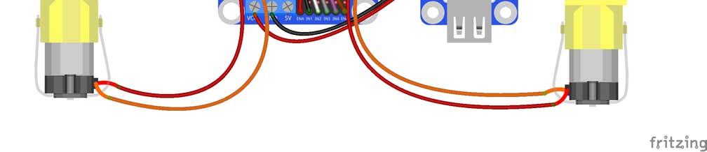
34 Step 1: Connect the two DC motors with the motor driver. You may remove the L-shaped PCB connector and plug it back after wiring. Note: It doesn't matter how to wire the motors. After all the assembly is done, if the car moves in an opposite direction of what you control, just swap the wiring of the two motors and it will work normally. After wiring, it should be like this: 31


35 Step 2: Connect the motor driver with the Raspberry Pi GPIO port based on the following table. Raspberry Pi GPIO Port Pin11 Pin12 Pin13 Pin15 DC Motor Driver IN1 IN2 IN3 IN4 32


 Pin 3 (SDA)")

36 Step 3: Connect the servo controller with the Raspberry Pi GPIO port as follows: Raspberry Pi GPIO Port Pin 2 (5V) Pin 3 (SDA) Pin 5 (SCL) GND Servo Controller VCC SDA SCL GND 33


37 Step 4: Hook up the servo that controls the car's direction to CH0 of the servo controller, and the two servos that control the view of the camera to CH14 and CH15 respectively, as shown below: Step 5: Connect the motor driver with the servo controller. 34


38 Step 6: Connect the servo controller with the step-down DC-DC converter module. For the connector, loosen the screws, insert the wire, and then tighten the screws with a screwdriver. The connection should be like: 35


39 Step 7: Connect the battery holder with the step-down DC-DC converter module and the DC motor driver. Note: Please DO NOT install the batteries at this step! Do it later when you've completed all the wiring. And take care that the red wire is the power and should be connected to the anode of the holder, when the black wire, i.e. the ground, to cathode. + - Insert the four wires into two jacks of the connector, two in each. Pay attention: the red wires to the anode of the step-down module, when the black ones to the cathode. Also DO NOT plug a red wire with a black one into the same jack, or it'll cause a short circuit!


40 The whole picture of wiring should be like this: 37


41 Step 8: Connect the Raspberry Pi with the step-down DC-DC converter module, the USB Wi-Fi adapter and the USB camera. 38


42 Now the circuit is completed. Congratulations! The car should be assembled successfully as shown below: 39

43 Electrical Components Basics i. Raspberry Pi The Raspberry Pi is a low cost, credit-card sized computer that plugs into a computer monitor or TV, and uses a standard keyboard and mouse. It is a capable little device that enables people of all ages to explore computing, and to learn how to program in languages like Scratch and Python. It's capable of doing everything you'd expect a desktop computer to do, from browsing the internet and playing high-definition video, to making spreadsheets, doing word-processing, and playing games. What's more, the Raspberry Pi has the ability to interact with the outside world, and has been used in a wide array of digital maker projects, from music machines and parent detectors to weather stations and tweeting birdhouses with infra-red cameras. In this kit, we use Raspberry Pi as the core controller of driving equipment like DC motor and servo. With the device and a camera collaborated, video data can be acquired in a real-time manner and delivered by Wi-Fi network. 40


.")
44 ii. Step-down DC-DC Converter Module Built based on the chip XL1509, the module converts the battery output of 7.4V to 5V, so as to supply power to Raspberry Pi and the servo. As a DC to DC converter IC, the chip has an input voltage ranging from 4.5V to 40V and generates an output voltage of 5V with a current of as high as 2A. Please note: only when the input voltage is up to 6.5V, a 5V output can be supported. iii. Servo In this smart car, one servo controls the direction of the car, and the other two, the movement of the camera between X axis and Y axis, thus defining the coverage of the camera. A servo is an automatic control system composed of DC motor, reduction gear set, sensor, and control circuit. It defines the rotation angle of the output shaft via delivering specific PWM signals. Generally, a servo supports a maximum rotation angle of the shaft (like 180 degrees). It differs from a common DC motor in the rotation mode: a DC motor rotates by circle when a servo rotates in a certain degree and does not rotate in a round circle. Also, the former is used for power supply by its whole-circle rotation, while the latter is applied to controlling the rotation angle of an object (like joints of a robot). 41


45 iv. DC Motor Driver As the name suggests, the module is used to drive DC motors. The driver is built based on L298N. As a high-voltage and large-current chip for motor driving, encapsulated with 15 pins, the chip has a maximum operating voltage of 46V and an instant peak current of as high as 3A, with an operating current of 2A and rated power of 25W. Thus, it is completely capable of driving two low-power DC motors. v. USB Wi-Fi Adaptor The adapter helps Raspberry Pi connect to a Wi-Fi hot spot. 42


46 vi. Servo Controller The Servo Controller is built based on PCA9685. PCA9685 is a 16-channel LED controller with I2C bus interface. The resolution ratio of each channel is 12 bits (2 12 =4096 levels). The controller works in a frequency between 40Hz and 1000Hz and its duty cycle can be adjusted in a range of 0 to 100%. It provides PWM signals for the servo and controls the rotation angle of the servo. Meanwhile, the module controls the duty cycle of the square waves output from channel 14 and 15 to regulate the rotational speed of the DC motor, so as to control the speed of the car. vii *2 Battery Holder The battery is to use two batteries to power the modules and servos on the car. Note: Please pay attention to the cathode (-) and anode (+) marks inside the holder (near each pole). Install the batteries accordingly: battery cathode to holder -, and battery anode to holder +. 43
47 Software Related i. Download and Install Raspbian on a TF Card If you've already installed the Raspbian system, please skip this step. Search out the installation guide for Raspbian on the Raspberry Pi website at Then download the Raspbian to your TF card and install it. After the installation, you may need some basic settings for the Raspberry Pi. Check out the guide for the setting on our website ii. Get Source Code Step 1. Download the source code directly from Github to your Raspberry Pi. cd ~ git clone it Step 2. Download the source code directly from Github to your Linux. Method 1 Open a terminal in your Linux. Download git: For Ubuntu/Debian: sudo apt-get install git-core git For Redhat/Fedora: sudo yum install git-core git Clone the repository from github: git clone it Method 2 If your Linux does not support installing git by yum or apt-get, download here: or search for Sunfounder in Github and find the repository: Sunfounder_Smart_Video_Car_Kit_for_RaspberryPi. 44
48 Click Download ZIP on the sidebar of the page, as shown below. After download, - Go to the file, right click on it, and click Extract here - Or unzip it by command: unzip Sunfounder_Smart_Video_Car_Kit_for_RaspberryPi-master.zip And then, change the folder name mv./sunfounder_smart_video_car_kit_for_raspberrypi-master ~/Sunfounder_Smart_Video_Car_ Kit_for_RaspberryPi iii. Basic Software Environment Operation on PC Prepare the PC for remote Install python-tk for a remote interface sudo install apt-get install python-tk For Windows users: Go to the Python website find the latest Python 2 and install. After installation, DO restart the computer. 45
49 Operation on Raspberry Pi Install python-dev, python-smbus Install python-dev and python-smbus: sudo apt-get update sudo apt-get upgrade sudo apt-get install python-dev sudo apt-get install python-smbus Setup I2C port Run the command to open Raspberry Pi Software Configuration Tool (raspi-config) sudo raspi-config Enable I2C: Select Advanced Options => I2C => <Yes> => <Ok> => <Yes> Select <Finish>. Close the window. If a message of rebooting appears, click <No>. Before reboot, we still need to complete some configurations. MJPG-streamer Introduction The acquisition and transmission of video data by the SunFounder Smart Video Car is fulfilled based on MJPG-streamer. MJPG-streamer is a command line application that copies JPG-frame from a single input plugin to multiple output plugins. It can be used to stream JPEG files over an IP-based network from the webcam to a viewer like Firefox, Cambozola and Videolanclient or even to a Windows mobile device running the TCPMP-Player. It was written for embedded devices with very limited resources in terms of RAM and CPU. Its origin, the "uvc_streamer" was written, because Linux-UVC compatible cameras directly produce JPEG-data, allowing fast and performant M-JPEG streams even from an embedded device running OpenWRT. The input module "input_uvc.so" captures such JPG frames from a connected webcam. Installation Plug the USB camera into Raspberry Pi, and run the command lsusb. The GEMBIRD represents the USB camera; since it is printed on the screen, it indicates the system has recognized the camera. lsusb You'll see: pi@raspberrypi:~ $ lsusb Bus 001 Device 004: ID 1908:2310 GEMBIRD Bus 001 Device 003: ID 0424:ec00 Standard Microsystems Corp. SMSC9512/9514 Fast Ethernet Adapter 46
50 Bus 001 Device 002: ID 0424:9514 Standard Microsystems Corp. Bus 001 Device 001: ID 1d6b:0002 Linux Foundation 2.0 root hub Check whether the driver for the camera works normally: ls /dev/vid* You'll see: $ ls /dev/vid* /dev/video0 If /dev/video0 is printed, the driver is in the normal state. Then, install the following software needed: sudo apt-get install subversion sudo apt-get install libv4l-dev sudo apt-get install libjpeg8-dev sudo apt-get install imagemagick Compile the source code of MJPG-streamer: cd /home/pi/sunfounder_smart_video_car_kit_for_raspberrypi/mjpg-streamer/mjpg-streamer sudo make USE_LIBV4L2=true clean all Install: sudo make DESTDIR=/usr install Testing Type in sudo sh start.sh and press Enter. Type in the following address (replace with your Raspberry Pi IP address) at the address bar of your browser (Firefox is recommended): Press Enter and you will see the view captured by the camera displayed on the screen in a realtime manner. 47

51 48


52 iv. Calibration Preparation Run the Server Run the calibration server on the Raspberry Pi, and wait for client to connect. Make sure that the circuit is connected properly. Power the smart car, open a terminal in Linux. Connect with your Raspberry Pi via the ssh. Go to the directory Sunfounder_Smart_Video_Car_Kit_for_RaspberryPi/server, run the server cali_server.py: if the servo gets stuck with an abnormal sound, unplug the wires at once, and redo servo adjustment for calibration in case of further damages. cd ~/Sunfounder_Smart_Video_Car_Kit_for_RaspberryPi/server sudo python cali_server.py Then the contents of config are printed and the last line: Waiting for connection At this time, the car might move a bit (this is the original position set) Run the Client Run the calibration client on PC to connect the server on Raspberry Pi. For Windows users: Unzip the code package you downloaded. Click the Start button on your computer, and type in python in the search bar, and you can find the IDLE (Python GUI). Click it and then a window will pop up. 49

.")
53 Click File -> Open -> Sunfounder_Smart_Video_Car_Kit_for_RaspberryPi-master -> client -> cali_client.py to open this file, modify the value of HOST for the IP address of the Raspberry Pi. After modification, save the file and click the Run menu, and select Run Module. For Linux users: Open another terminal in Linux (not via ssh on your Pi). Find the sketch downloaded and edit client/cali_client.py: cd client/ sudo nano cali_client.py Find the variable of HOST: 50
54 Enter your own address of the Raspberry Pi there. Press Ctrl+O to save and Ctrl+X exit. Run cali_client.py: sudo python cali_client.py No matter what system your computer is running on, Linux or Windows, when you run cali_client.py, a window Raspberry Pi Smart Video Car Calibration will pop up: In the terminal remotely connected with the Raspberry Pi, the IP address of the PC will be printed. Then you can start calibrating. Before that, take out your package box and place it vertically with the side face to the table. Put the car onside the box and keep it balanced. The purpose is to keep the wheels of the car off the table. By default, the front wheels should be directly pointed towards the front; the camera on the tilt servo should be face up no matter what directions the pan servo is pointed at. If not, you may adjust the directions in Raspberry Pi Smart Video Car Calibration. 51

55 Start Calibration On the calibration UI there are three sections: Motor, Turning, and Mount. Motor Adjustment Click Run. The car will walk forward. Check whether both the back wheels move forward together. If either fails to do so, your wiring may be wrong. But don't worry! You don't need to rewire; just click the corresponding Reverse in Motor section of the Calibration window shown above. After clicking, observe whether the wheel you just adjusted is turning forward. If the reversing works normally, click Run again to stop the wheels from spinning. Turning Adjustment Currently the front wheels should be pointed at the exact front direction. But if it is not, you need to make some adjustments. In the Turning section in the Calibration window, click the left ( ) and right ( ) arrow buttons in the upper line to make fine adjustments, and those in the lower to coarsely adjust the turning direction. Keep adjusting until the wheels is oriented to the front exactly. Then you may place the car on the table and click Run to verify whether it runs in a straight line. If not, perform the adjustment again till it does. 52

56 Mount Adjustment Now the pan servo on the car should be pointed at the exact front direction and the camera face up. But if not, you may need to adjust them similarly. In the Mount section, there are the adjustments for the pan servo and tilt one. Also you have two kinds of adjustments, fine and coarse. Keep adjusting until they are pointed at the right direction. After all the adjustments are done, click Confirm. And the program will exit. Then the Raspberry Pi returns to the status: Waiting for connection... Press Ctrl + C to exit NOW YOUR CAR IS READY TO GO!

57 Get on the Road! Run the Server Run the TCP server on the Raspberry Pi, and wait for the client to connect to control the car. You need two terminals to run the server. One is to run tcp_client.py to receive commands to control the car, and the other to run mjpg-streamer to provide video streams. In Windows, you can use PuTTy to remotely log into the Raspberry Pi to start the server. Open a terminal. The Raspberry Pi may be still at the server directory: pi@raspberrypi ~/Sunfounder_Smart_Video_Car_Kit_for_RaspberryPi/server $ If not, go to the directory with cd. cd ~/Sunfounder_Smart_Video_Car_Kit_for_RaspberryPi/server Then run tcp_server.py: sudo python tcp_server.py The server program on the Raspberry Pi will be running and waiting for the client to connect to the Raspberry Pi. Open another terminal. Log in the Raspberry Pi remotely, and switch to the directory under which the program of MJPG-streamer lies: cd ~/Sunfounder_Smart_Video_Car_Kit_for_RaspberryPi/mjpg-streamer/mjpg-streamer Run the program: sudo sh start.sh 54
 at the address bar of your browser (Firefox is recommended): http://192.")

58 Then the video data acquisition will start, like this: Type in the following address (replace xxx with the IP address of your Raspberry Pi) at the address bar of your browser (Firefox is recommended): Press Enter and you will see the view captured by the camera displayed on the screen in a realtime manner. Run the Client Run the client on PC to connect the server on the Raspberry Pi. For Windows users: Open the IDLE 55


59 Click File -> Open -> Sunfounder_Smart_Video_Car_Kit_for_RaspberryPi-master -> client -> client App.py to open this file, modify the value of the HOST for the IP address of the Raspberry Pi. After modification, save the file and select Run -> Run Module. For Linux users: Open another terminal again. But do not log into the Raspberry Pi remotely in this terminal. Go to the client with cd and edit the file client.py: Similar to changes in calibration, change the IP address in client program in your PC: After the alteration, press Ctrl + O and save and Ctrl + X to exit. 56

60 Then run the client program: sudo python client_app.py No matter what system your computer is running on, Linux or Windows, when you run the client_app.py, the following window will appear on your screen: You can click buttons such as Forward and Backward to control the car moving remotely. Or click X+, X-, Y+, and Y- to control the coverage of the camera. Note: The server program must be run before you run the client program. Some settings must be completed for the server before the service is done. A communication endpoint needs to be created for the server to "listen" to requests from the client. Take the server as a receptionist or an operator of the bus phone in a company. Once the phone and device installation is completed and the receptionist or operator is in place, the service begins. 57
61 v. Program Analysis and Explanation Abstract From the perspective of software, the smart car is of C/S structure. The TCP server program is run on Raspberry Pi to listen to the command from the client and control the car accordingly. The client program is run on the PC and connected with the server through the TCP, which provides the user with a graphical user interface (GUI) to conveniently control the Raspberry Pi remotely. Both the client and server programs are written in Python. Make sure that the circuit is connected properly. Power the smart car, log in the Raspberry Pi remotely, go to the directory Sunfounder_Smart_Video_Car_Kit_for_RaspberryPi and check the files under it. cd ~/Sunfounder_Smart_Video_Car_Kit_for_RaspberryPi ls pi@raspberrypi ~/Sunfounder_Smart_Video_Car_Kit_for_RaspberryPi $ ls client datasheet html_server i2chelper.py mjpg-streamer README.md server You can see seven files under the directory: client, datasheet, html_server, i2chelper.py, mjpgstreamer, a file README.md, and server. Wherein, client, the client run on your PC, datasheet contains some PDF files about the chip (you need to view them on PC), html_server, the web server run on the Raspberry Pi for Android app client, i2chelper, a simple script to help you set up i2c on the Raspberry Pi, mjpg-streamer, the camera driver to acquire and upload images, README.md, an introduction file with update information, server, the server run on the Raspberry Pi for the client on your PC. Introduction of Socket The C/S-structure program of the SunFounder Raspberry Pi-based Smart Car is written based on the socket module of the Python language. Socket wraps and applies the TCP/IP and is used to describe IP address and port. Also it is a network data structure for computer. The socket module should be created before the communication of network applications. If the socket can be said to be the plug of a telephone, which is the lowest layer of communication, then the combination of IP address and ports can be said to be that of area code and phone numbers. Only having the hardware for a phone call making is not enough. You still need to know whom and where to call. An Internet address is composed of the essential IP address and port for network communication. 1. Server Here we provide a pseudocode which creates a universal TCP server for explanation. Note that this is just one of the methods for server design. After you have a good knowledge about it, you can alter the pseudocode as you want: 58
62 s = socket( ) s.bind( ) s.listen( ) inf_loop: c = s.accept( ) comm_loop: c.recv( )/c.send( ) c.close( ) s.close( ) # Create a socket for the server. # Bind the address to the socket. # Listen to the connection. # Indefinite loop of the server. # Accept the connection from the client. # Communication loop. # Dialog (receiving or sending data) # Close the socket of the client. # Close the socket of the server (optional). All kinds of socket can be created via the function socket.socket( ) and then bound with IP address and port by the function bind( ). Since TCP is a connection-oriented communication system, some settings need to be completed before the TCP server starts operation. The TCP server must "listen" to connections from the client. After the settings are done, the server will enter an indefinite loop. A simple, like single-thread, server will call the function accept( ) to wait for the coming connection. By default, the function accept( ) is a blocking one, which means it is suspended before the connection comes. Once a connection is received, the function accept( ) returns a separate client socket for the subsequent communication. After the temporary socket is created, communication begins. Both the server and client use the new socket for data sending and receiving. The communication does not end until either end closes the connection or sends a null character string. Process Diagram of Server Program 59
63 2. Client It is easier to create a TCP client than to do a server. Take the following pseudocode: c = socket( ) c.connect( ) comm_loop: c.send( )/c.recv( ) c.close( ) # Create a client socket. # Try to connect a server. # Communication loop. # Dialog (sending out and receiving data) # Close the client socket. As mentioned above, all sockets are created via the function socket.socket( ). Then, the function connect( ) can be called to connect the server. After the connection is built, the dialog between the client and the server is enabled. When the dialog ends, the client can close the socket and the connection. Introduction of Tkinter Developed based on Tkinter, our client program carries graphical interfaces. Tkinter is a GUI widget set for Python. We can develop application programs with graphical interfaces fast by Python language based on it. It is quite easy to use Tkinter. All you have to do is to import the module into Python. To create and run a GUI program, take the following steps: a) Import the Tkinter module (by import Tkinter or from Tkinter import *). b) Create a top window object to contain the whole GUI program. c) Create the GUI module needed on the object and enable the functions. d) Connect the GUI modules with the code at the system back-end. e) Enter the main event loop. Take a simple GUI program: Create a file Tk_test.py under the path /home: touch Tk_test.py Add executable privilege to the file: chmod +x Tk_test.py Open the file: vim Tk_test.py Type in the following code: #!/usr/bin/env python from Tkinter import * top = Tk() # Create a top window top.title('sunfounder.com') label = Label(top, text='hello Geeks!', fg='blue') # Create a label and set its foreground color as blue label.pack() # layout 60
64 top.mainloop() # main loop Save the code and exit. Run./Tk_test.py Then the following picture will appear on your screen: Click to close the program. Process Diagram of Client Program 61

65 Summary In this manual, having learned the related components for building the car kit, you've gone through the assembly of the mechanical parts and electrical modules with the knowledge of Raspberry Pi as well as a brief introduction of the key parts like servo, Wi-Fi adapter, etc. Also you've got a lot of software and coding, which lays a solid foundation for your future journey of exploring open-source field. The SunFounder Smart Video Car for Raspberry Pi is not only a toy, but more a meaningful development kit for Raspberry Pi. After all the study and hands-on practice of the kit, you should have a better understanding of Raspberry Pi. Now, get started to make better work! 62
66 Copyright Notice All contents including but not limited to texts, images, and code in this manual are owned by the SunFounder Company. You should only use it for personal study, investigation, enjoyment, or other non-commercial or nonprofit purposes, under the related regulations and copyrights laws, without infringing the legal rights of the author and relevant right holders. For any individual or organization that uses these for commercial profit without permission, the Company reserves the right to take legal action. 63
Preface. If you have any TECHNICAL questions, add a topic under FORUM section on our website and we'll reply as soon as possible.
 Preface About SunFounder SunFounder is a technology company focused on Raspberry Pi and Arduino open source community development. Committed to the promotion of open source culture, we strive to bring
Content Components... 1 i. Acrylic Plates... 1 ii. Mechanical Fasteners... 3 iii. Electrical Components... 4 Introduction... 5 Getting Started... 6 Ar
 About r Preface r is a technology company focused on Raspberry Pi and Arduino open source community development. Committed to the promotion of open source culture, we strive to bring the fun of electronics
Preface. If you have any TECHNICAL questions, add a topic under FORUM section on our website and we'll reply as soon as possible.
 Preface About is a technology company focused on Raspberry Pi and Arduino open source community development. Committed to the promotion of open source culture, we strive to bring the fun of electronics
Preface. About SunFounder. About the PiCar-S. Free Support
 Preface About SunFounder SunFounder is a technology company focused on Raspberry Pi and Arduino open source community development. Committed to the promotion of open source culture, we strive to bring
Adafruit 16 Channel Servo Driver with Raspberry Pi
 Adafruit 16 Channel Servo Driver with Raspberry Pi Created by Kevin Townsend Last updated on 2014-04-17 09:15:51 PM EDT Guide Contents Guide Contents Overview What you'll need Configuring Your Pi for I2C
Adafruit 16-Channel PWM/Servo HAT & Bonnet for Raspberry Pi
 Adafruit 16-Channel PWM/Servo HAT & Bonnet for Raspberry Pi Created by lady ada Last updated on 2018-03-21 09:56:10 PM UTC Guide Contents Guide Contents Overview Powering Servos Powering Servos / PWM OR
Adafruit 16-Channel PWM/Servo HAT for Raspberry Pi
 Adafruit 16-Channel PWM/Servo HAT for Raspberry Pi Created by lady ada Last updated on 2017-05-19 08:55:07 PM UTC Guide Contents Guide Contents Overview Powering Servos Powering Servos / PWM OR Current
1. ASSEMBLING THE PCB 2. FLASH THE ZIP LEDs 3. BUILDING THE WHEELS
 V1.0 :MOVE The Kitronik :MOVE mini for the BBC micro:bit provides an introduction to robotics. The :MOVE mini is a 2 wheeled robot, suitable for both remote control and autonomous operation. A range of
Gravity: 12-Bit I2C DAC Module SKU: DFR0552
 Gravity: 12-Bit I2C DAC Module SKU: DFR0552 Introduction DFRobot Gravity 12-Bit I2C DAC is a small and easy-to-use 12-bit digital-to-analog converter with EEPROM. It can accurately convert the digital
가치창조기술. Motors need a lot of energy, especially cheap motors since they're less efficient.
 Overview Motor/Stepper/Servo HAT for Raspberry Pi Let your robotic dreams come true with the new DC+Stepper Motor HAT. This Raspberry Pi add-on is perfect for any motion project as it can drive up to 4
Bipedinno. 12-DOF Waist-high Robot
 Bipedinno 12-DOF Waist-high Robot Instruction Manual Version 1.18 Trademark Innovati,, and BASIC Commander, are registered trademarks of Innovati Inc. InnoBASIC and cmdbus are trademarks of Innovati Inc.
Mini Hexapodinno. 18-DOF Robot
 Mini Hexapodinno 18-DOF Robot Instruction Manual Version 1.11 Trademark Innovati,, and BASIC Commander, are registered trademarks of Innovati Inc. InnoBASIC and cmdbus are trademarks of Innovati Inc. Copyright
Internet of Things Student STEM Project Jackson High School. Lesson 2: Arduino and LED
 Internet of Things Student STEM Project Jackson High School Lesson 2: Arduino and LED Lesson 2: Arduino and LED Time to complete Lesson 60-minute class period Learning objectives Students learn about Arduino
Pi Servo Hat Hookup Guide
 Page 1 of 10 Pi Servo Hat Hookup Guide Introduction The SparkFun Pi Servo Hat allows your Raspberry Pi to control up to 16 servo motors via I2C connection. This saves GPIO and lets you use the onboard
Setting up Volumio to get great audio
 Home News DAC Digi Amp Shop Guides/Support About us About us 0 items My Account Home Guides Setting up Volumio to get great audio Setting up Volumio to get great audio Here is a simple way to use a HiFiBerry
OpenROV. Guide 3 - Electronics. We will now move to the assembly of the electronics that will control the ROV. Written By: OpenROV
 OpenROV Guide 3 - Electronics We will now move to the assembly of the electronics that will control the ROV. Written By: OpenROV 2017 openrov.dozuki.com Page 1 of 33 INTRODUCTION We will introduce soldering
Running the PR2. Chapter Getting set up Out of the box Batteries and power
 Chapter 5 Running the PR2 Running the PR2 requires a basic understanding of ROS (http://www.ros.org), the BSD-licensed Robot Operating System. A ROS system consists of multiple processes running on multiple
Assembly Guide for Printrbot - Simple Maker s Edition 1405
 Assembly Guide for Printrbot - Simple Maker s Edition 1405 Last update: March 2016 Please Note: be careful on the steps that are underlined 1 Contents Tools Needed:... 3 First step: Check components and
meped v2 Assembly Manual
 meped v Assembly Manual The meped is an open source quadruped robot designed by Scott Pierce of Spierce Technologies, LLC. This design is released under the Creative Commons, By Attribution, Share Alike
StenBOT Robot Kit. Stensat Group LLC, Copyright 2018
 StenBOT Robot Kit 1 Stensat Group LLC, Copyright 2018 Legal Stuff Stensat Group LLC assumes no responsibility and/or liability for the use of the kit and documentation. There is a 90 day warranty for the
Congratulations on your decision to purchase the Triquetra Auto Zero Touch Plate for All Three Axis.
 Congratulations on your decision to purchase the Triquetra Auto Zero Touch Plate for All Three Axis. This user guide along with the videos included on the CD should have you on your way to perfect zero
Printrbot Simple (Model 1403) Rev F Printrboard
 Rev F Printrboard") Printrbot Simple (Model 1403) Rev F Printrboard Printrbot Simple is currently shipping with the Rev F Printrboard. Check which rev Printrboard your Simple kit includes and use the corresponding instructions.
Printrbot Simple (Model 1403) Rev F Printrboard Printrbot Simple is currently shipping with the Rev F Printrboard. Check which rev Printrboard your Simple kit includes and use the corresponding instructions.
ZX Distance and Gesture Sensor Hookup Guide
 Page 1 of 13 ZX Distance and Gesture Sensor Hookup Guide Introduction The ZX Distance and Gesture Sensor is a collaboration product with XYZ Interactive. The very smart people at XYZ Interactive have created
OWEN Walking Robot Install Guide
 OWEN Walking Robot Install Guide The 3D printed parts are as follows: - Left Foot - Right Foot - Ankles (both are identical) - Pelvis Servo, arm, and screws: FIRST STEPS Connect the battery to the ODROID-C0.
The CO2 Sensor Calibration Kit
 The CO2 Sensor Kit For use with all BAPI CO 2 Sensors Instruction Manual CO 2 Kit Product Identification and Overview BAPI s CO 2 Sensor Kit is designed to calibrate and verify the operation of all BAPI
1 Day Robot Building (MC40A + Aluminum Base) for Edubot 2.0
 for Edubot 2.0") 1 Day Robot Building (MC40A + Aluminum Base) for Edubot 2.0 Have you ever thought of making a mobile robot in 1 day? Now you have the chance with MC40A Mini Mobile Robot Controller + some accessories.
1 Day Robot Building (MC40A + Aluminum Base) for Edubot 2.0 Have you ever thought of making a mobile robot in 1 day? Now you have the chance with MC40A Mini Mobile Robot Controller + some accessories.
Adafruit SGP30 TVOC/eCO2 Gas Sensor
 Adafruit SGP30 TVOC/eCO2 Gas Sensor Created by lady ada Last updated on 2018-08-22 04:05:08 PM UTC Guide Contents Guide Contents Overview Pinouts Power Pins: Data Pins Arduino Test Wiring Install Adafruit_SGP30
Motor Driver HAT User Manual
 Motor Driver HAT User Manual OVERVIE This module is a motor driver board for Raspberry Pi. Use I2C interface, could be used for Robot applications. FEATURES Compatible with Raspberry Pi I2C interface.
STEP BY STEP GUIDE (RASPBERRY PI)
") STEP BY STEP GUIDE (RASPBERRY PI) Raspberry Pi The Raspberry Pi is a credit-card-sized single-board computer developed in the UK by the Raspberry Pi Foundation with the intention of promoting the teaching
STEP BY STEP GUIDE (RASPBERRY PI) Raspberry Pi The Raspberry Pi is a credit-card-sized single-board computer developed in the UK by the Raspberry Pi Foundation with the intention of promoting the teaching
smraza Getting Start Guide Contents Arduino IDE (Integrated Development Environment)... 1 Introduction... 1 Install the Arduino Software (IDE)...
... 1 Introduction... 1 Install the Arduino Software (IDE)...") Getting Start Guide Contents Arduino IDE (Integrated Development Environment)... 1 Introduction... 1 Install the Arduino Software (IDE)...1 Introduction... 1 Step 1: Get an Uno R3 and USB cable... 2 Step
Getting Start Guide Contents Arduino IDE (Integrated Development Environment)... 1 Introduction... 1 Install the Arduino Software (IDE)...1 Introduction... 1 Step 1: Get an Uno R3 and USB cable... 2 Step
Sten-Bot Robot Kit Stensat Group LLC, Copyright 2013
 Sten-Bot Robot Kit Stensat Group LLC, Copyright 2013 Legal Stuff Stensat Group LLC assumes no responsibility and/or liability for the use of the kit and documentation. There is a 90 day warranty for the
Assembly Guide Robokits India
 Robotic Arm 5 DOF Assembly Guide Robokits India info@robokits.co.in Robokits World http://www.robokitsworld.com http://www.robokitsworld.com Page 1 Overview : 5 DOF Robotic Arm from Robokits is a robotic
tinycylon Assembly Instructions Contents Written by Dale Wheat Version August 2016 Visit dalewheat.com for the latest update!
 tinycylon Assembly Instructions Written by Dale Wheat Version 2.1 10 August 2016 Visit dalewheat.com for the latest update! Contents Assembly Instructions...1 Contents...1 Introduction...2 Quick Start
J. La Favre Using Arduino with Raspberry Pi February 7, 2018
 As you have already discovered, the Raspberry Pi is a very capable digital device. Nevertheless, it does have some weaknesses. For example, it does not produce a clean pulse width modulation output (unless
Installation guide. Activate. Install your TV. Uninstall. 1 min 10 mins. 30 mins
 Installation guide 1 Activate 2 Uninstall 3 Install your TV 1 min 10 mins 30 mins INT This guide contains step-by-step instructions on how to: 1 Activate Before we do anything else, reply GO to the text
The ideal K-12 science microscope solution. User Guide. for use with the Nova5000
 The ideal K-12 science microscope solution User Guide for use with the Nova5000 NovaScope User Guide Information in this document is subject to change without notice. 2009 Fourier Systems Ltd. All rights
Studuino Icon Programming Environment Guide
 Studuino Icon Programming Environment Guide Ver 0.9.6 4/17/2014 This manual introduces the Studuino Software environment. As the Studuino programming environment develops, these instructions may be edited
Version: 2.0 Date: 5/31/ :07:00 AM
 Weavefuture Coin Op Internet Café Kiosk System 2.0 Version: 2.0 Date: 5/31/2007 12:07:00 AM Table of Contents 1 WEAVEFUTURE COIN OP INTERNET CAFÉ KIOSK SYSTEM COMPOSITION... 3 2 WEAVEFUTURE COIN ACCEPTOR
Adafruit 16-Channel Servo Driver with Arduino
 Adafruit 16-Channel Servo Driver with Arduino Created by Bill Earl Last updated on 2017-11-26 09:41:23 PM UTC Guide Contents Guide Contents Overview Assembly Install the Servo Headers Solder all pins Add
ABM International, Inc. Navigator Assembly Manual
 ABM International, Inc. 1 1.0: Parts List Tablet (Qty. 1) Tablet mount (Qty. 1) NOTE: Mount may appear and operate different then image below Control Box (Qty. 1) Motor Power Supply (Qty. 1) 2 X-axis motor
The DesignaKnit USB E6000 Link 1 & 2
 The DesignaKnit USB E6000 Link 1 & 2 for the Passap / Pfaff Electronic 6000 USB E6000 Link 1 USB E6000 Link 2 What these links do The USB E6000 Link 1 enables downloading of stitch patterns from DesignaKnit
Installation guide. Activate. Install your Broadband. Install your Phone. Install your TV. 1 min. 30 mins
 Installation guide 1 Activate Install your Broadband Install your TV 4 Install your Phone 1 min 0 mins 0 mins 5 mins INT This guide contains step-by-step instructions on how to: 1 Activate Before we do
Endurance R/C Wi-Fi Servo Controller 2 Instructions
 Endurance R/C Wi-Fi Servo Controller 2 Instructions The Endurance R/C Wi-Fi Servo Controller 2 allows you to control up to eight hobby servos, R/C relays, light controllers and more, across the internet
ECE 511: FINAL PROJECT REPORT GROUP 7 MSP430 TANK
 ECE 511: FINAL PROJECT REPORT GROUP 7 MSP430 TANK Team Members: Andrew Blanford Matthew Drummond Krishnaveni Das Dheeraj Reddy 1 Abstract: The goal of the project was to build an interactive and mobile
About the DSR Dropout, Surge, Ripple Simulator and AC/DC Voltage Source
 About the DSR 100-15 Dropout, Surge, Ripple Simulator and AC/DC Voltage Source Congratulations on your purchase of a DSR 100-15 AE Techron dropout, surge, ripple simulator and AC/DC voltage source. The
Ribcage Installation. Part 2 - Assembly. Back-Bone V1.06
 Ribcage Installation Part 2 - Assembly Back-Bone V1.06 Contents Section 1 Before You Get Started... 2 Included With Your Kit:... 2 Figure: A... 3 CAUTION!... 4 Note:... 4 Tools Required... 5 Section 2:
ABM International, Inc.
 ABM International, Inc. Lightning Stitch required 1 1.0: Parts List head and motor assembly (Qty. 1) Reel stand (Qty. 1) Needle bar frame clamp (Qty. 1) Motor drive (Qty. 1) 2 Cable harness with bracket
Parts List. Robotic Arm segments ¼ inch screws Cable XBEE module or Wifi module
 Robotic Arm 1 Legal Stuff Stensat Group LLC assumes no responsibility and/or liability for the use of the kit and documentation. There is a 90 day warranty for the Sten-Bot kit against component defects.
OpenROV. Guide 6 - Finishing. These are the final steps to prepare your ROV for testing and flight. Written By: OpenROV
 OpenROV Guide 6 - Finishing These are the final steps to prepare your ROV for testing and flight. Written By: OpenROV 2017 openrov.dozuki.com Page 1 of 26 INTRODUCTION It it time to apply the finishing
Adafruit 16-channel PWM/Servo Shield
 Adafruit 16-channel PWM/Servo Shield Created by lady ada Last updated on 2018-08-22 03:36:11 PM UTC Guide Contents Guide Contents Overview Assembly Shield Connections Pins Used Connecting other I2C devices
Adafruit 16-channel PWM/Servo Shield
 Adafruit 16-channel PWM/Servo Shield Created by lady ada Last updated on 2017-06-29 07:25:45 PM UTC Guide Contents Guide Contents Overview Assembly Shield Connections Pins Used Connecting other I2C devices
User Manual. User Manual. Version Last change : March Page 1 ID station User Manual
 User Manual Version 7.4.3 Last change : March 2017 Page 1 Introduction This is the user manual of the new fastid, the biometric ID and passport photo system. This user guide helps you in everyday use.
Adafruit 16-Channel Servo Driver with Arduino
 Adafruit 16-Channel Servo Driver with Arduino Created by Bill Earl Last updated on 2015-09-29 06:19:37 PM EDT Guide Contents Guide Contents Overview Assembly Install the Servo Headers Solder all pins Add
CodeBug I2C Tether Documentation
 CodeBug I2C Tether Documentation Release 0.3.0 Thomas Preston January 21, 2017 Contents 1 Installation 3 1.1 Setting up CodeBug........................................... 3 1.2 Install codebug_i2c_tether
Underwater GPS User Manual
 Underwater GPS Document number W-DN-17002-3 Project Classification - Rev Prepared by Checked by Approved by Short description 1 2017-08-03 T. Trøite O. Skisland T. Trøite Initial 2 2017-08-04 T. Trøite
Mill One V2 Assembly Manual
 Mill One V2 Assembly Manual Throughout this policy the words "we", "us" and "our", or Sienci Labs will be used to refer to Sienci Labs Inc. herein and Mill One or machine will refer to Sienci Labs Sienci
9/Working with Webcams
 9/Working with Webcams One of the advantages to using a platform like the Raspberry Pi for DIY technology projects is that it supports a wide range of USB devices. Not only can you hook up a keyboard and
ABC V1.0 ASSEMBLY IMPORTANT!
 ABC V1.0 ASSEMBLY Before starting this kit, prepare the following tools: Soldering iron (15-20W will do), flush cutters, no.2 hex screwdriver or allen key and phillips screwdriver. Also briefly go through
Maintenance Information
 47104302 Edition 1 November 2012 Cordless Drill/Driver QX Series Maintenance Information Save These Instructions Tool Diagnosis 1. Before servicing this unit, you will need a fully charged battery of known
Lead Screw Upgrade. How to upgrade your ROBO R1 to the new Lead Screw Upgrade Pack. Written By: Harrison Team RoBo 3D
 Lead Screw Upgrade How to upgrade your ROBO R1 to the new Lead Screw Upgrade Pack. Written By: Harrison Team RoBo 3D 2017 guide.robo3d.com Page 1 of 14 Step 1 Lead Screw Upgrade Begin by powering off and
Standard Operating Procedure
 RIT MULTIDISCIPLINARY SENIOR DESIGN 2010 Standard Operating Procedure Baja Water Propulsion Test Stand This SOP specifies how to assemble, use, troubleshoot, and disassemble the water propulsion system
INSTANT ROBOT SHIELD (AXE408)
") INSTANT ROBOT SHIELD (AXE408) 1.0 Introduction Thank you for purchasing this Instant Robot shield. This datasheet is designed to give a brief introduction to how the shield is assembled, used and configured.
INSTANT ROBOT SHIELD (AXE408) 1.0 Introduction Thank you for purchasing this Instant Robot shield. This datasheet is designed to give a brief introduction to how the shield is assembled, used and configured.
Code Product Qty 1 Top Vertex 3 2 Hot End Housing 1 3 Bottom Vertex 3 4 Print Platform Lock 3 5 End Stop Holder 3 6 Filament Feeder Motor Bracket 1 7
 List of Parts Code Product Qty 1 680mm Extrusion 3 2 Power Supply 1 3 240mm Extrusion 9 4 42mm Nema 17 Stepper Motor 3 5 Slider-Hotend Connecting Rod 6 6 48mm Nema 17 Stepper Motor 1 7 Linear Rail with
Kodiak Corporate Administration Tool
 AT&T Business Mobility Kodiak Corporate Administration Tool User Guide Release 8.3 Table of Contents Introduction and Key Features 2 Getting Started 2 Navigate the Corporate Administration Tool 2 Manage
Tin Lizzie 18 Assembly Instructions
 Tin Lizzie 18 Assembly Instructions Revision: 07/29/16 Table of Contents Aides 3 Before You Begin 5 Aides 5 Tools 6 Perfect Stitch Parts 2 12 Modify the Machine 12 Prepare Drill Templates 12 Front Display
Infoblox and Ansible Integration
 DEPLOYMENT GUIDE Infoblox and Ansible Integration Ansible 2.5 April 2018 2018 Infoblox Inc. All rights reserved. Ansible Deployment Guide April 2018 Page 1 of 12 Contents Overview... 3 Introduction...
(Assembling Guide supplied by imakr ) with the support of MyMiniFactory.com
 with the support of MyMiniFactory.com") (Assembling Guide supplied by imakr ) with the support of MyMiniFactory.com Summary Congratulations on beginning on your journey into 3D printing with the STARTT 3D printer. In this guide, you will have
(Assembling Guide supplied by imakr ) with the support of MyMiniFactory.com Summary Congratulations on beginning on your journey into 3D printing with the STARTT 3D printer. In this guide, you will have
Vision Ques t. Vision Quest. Use the Vision Sensor to drive your robot in Vision Quest!
 Vision Ques t Vision Quest Use the Vision Sensor to drive your robot in Vision Quest! Seek Discover new hands-on builds and programming opportunities to further your understanding of a subject matter.
Adafruit's Raspberry Pi Lesson 8. Using a Servo Motor
 Adafruit's Raspberry Pi Lesson 8. Using a Servo Motor Created by Simon Monk Last updated on 2016-11-03 06:17:53 AM UTC Guide Contents Guide Contents Overview Parts Part Qty Servo Motors Hardware Software
iphoto Getting Started Get to know iphoto and learn how to import and organize your photos, and create a photo slideshow and book.
 iphoto Getting Started Get to know iphoto and learn how to import and organize your photos, and create a photo slideshow and book. 1 Contents Chapter 1 3 Welcome to iphoto 3 What You ll Learn 4 Before
Medb ot. Medbot. Learn about robot behaviors as you transport medicine in a hospital with Medbot!
 Medb ot Medbot Learn about robot behaviors as you transport medicine in a hospital with Medbot! Seek Discover new hands-on builds and programming opportunities to further your understanding of a subject
- Introduction - Minecraft Pi Edition. - Introduction - What you will need. - Introduction - Running Minecraft
 1 CrowPi with MineCraft Pi Edition - Introduction - Minecraft Pi Edition - Introduction - What you will need - Introduction - Running Minecraft - Introduction - Playing Multiplayer with more CrowPi s -
MILL ONE. Assembly Manual. Manual Illustrated by Gontarz Design Studio
 MILL ONE Assembly Manual Manual Illustrated by Gontarz Design Studio Safety Warnings and Guidelines 1. Be sure to carefully follow provided machine assembly instructions before machine use to ensure operator
PUMAVI Embossing machine Service Manual Note taking Writing Printing in Braille. If it s Braille...ask BRAILLETEC
 PUMAVI Embossing machine Service Manual Service manual for PumaVI Using the PumaVI To do 1.1 1.2 1.3 1.4 1.5 1.6 1.7 page Switches for format, graphics and mode Start the Puma Function of red lamps H1H3
EITN90 Radar and Remote Sensing Lab 2
 EITN90 Radar and Remote Sensing Lab 2 February 8, 2018 1 Learning outcomes This lab demonstrates the basic operation of a frequency modulated continuous wave (FMCW) radar, capable of range and velocity
FBX-PA-2AC. Third edition : April No
 FBX-PA-2AC Third edition : April 2006 No. 060058 INTRODUCTION Thank you very much for purchasing Kansai Special FBX series. Read and study this Instruction Manual carefully before you start any of the
WARNING: Prior to installation, turn the power off to the vending machine and unplug it from its power source. Also, make sure to level the machine.
 Installation of Gum and Mint Tray for National 147, 157, 167 Important Note: Please read all instructions thoroughly before continuing with installation of kit. If you are having problems installing the
Contribute to CircuitPython with Git and GitHub
 Contribute to CircuitPython with Git and GitHub Created by Kattni Rembor Last updated on 2018-07-25 10:04:11 PM UTC Guide Contents Guide Contents Overview Requirements Expectations Grab Your Fork Clone
SC16A SERVO CONTROLLER
 SC16A SERVO CONTROLLER User s Manual V2.0 September 2008 Information contained in this publication regarding device applications and the like is intended through suggestion only and may be superseded by
Installation Tutorial
 Installation Tutorial 1. Remove the finger parts, if the film, tear off the surface of the film, the number of parts were 1 4 4 5 5 2. First assemble the big finger parts, use M2X3 screws, M2X6 copper
MAKEBLOCK MUSIC ROBOT KIT V2.0
 MAKEBLOCK MUSIC ROBOT KIT V2.0 Catalog Music Robot Kit V2.0 Introduction... 1 1 What is Music Robot Kit V2.0?... 1 1.1 Mechanical part... 1 1.2 Electronic part... 1 1.3 Software part... 1 2 Music Robot
Instructions to build the Hexapod in plywood
 Instructions to build the Hexapod in plywood Author: Jørgen Vendorf Disclaimer The author can in no regards be held responsible for anything regarding this instruction, drawings or anything that goes wrong
Copyright 2014 SOTA Imaging. All rights reserved. The CLIOSOFT software includes the following parts copyrighted by other parties:
 2.0 User Manual Copyright 2014 SOTA Imaging. All rights reserved. This manual and the software described herein are protected by copyright laws and international copyright treaties, as well as other intellectual
Field Service Procedure Replacement Pol Motor Kit, Coastal
 1. Brief Summary: Troubleshooting document for diagnosing a fault with and replacing the pol motor on the Coastal series antennas. 2. Checklist: Verify Motor Drive Drive the Pol from Progterm Run the Built
Installing a 3 Indexer: Desktop Tools
 888-680-4466 ShopBotTools.com Installing a 3 Indexer: Desktop Tools built after October, 2012 Copyright 2016 ShopBot Tools, Inc. page 1 Copyright 2016 ShopBot Tools, Inc. page 2 Table of Contents Overview...5
Annex IV - Stencyl Tutorial
 Annex IV - Stencyl Tutorial This short, hands-on tutorial will walk you through the steps needed to create a simple platformer using premade content, so that you can become familiar with the main parts
Pingable Envelope Generator
 Pingable Envelope Generator Kit Builder's Guide for PCB v1.0.3 4mspedals.com PEG This guide is for building a Pingable Envelope Generator (PEG), which is an intermediate-level kit. You should be confident
Instructions for the W0NE Remote HF Rig, IC-7300
 Instructions for the W0NE Remote HF Rig, IC-7300 The ICOM IC-7300 rig at the Witoka site is installed and connected up as a RemoteHams.com Server. This system is being opened to all W0NE club members to
Tarocco Closed Loop Motor Controller
 Contents Safety Information... 3 Overview... 4 Features... 4 SoC for Closed Loop Control... 4 Gate Driver... 5 MOSFETs in H Bridge Configuration... 5 Device Characteristics... 6 Installation... 7 Motor
Written By: Brook Drumm
 Simple 1401 Assembly For kits produced between 1/15/14-6/1/14. This guide is for kits with the Fan Shroud. Instructions for metal and wood extruder (and bed) included below. Written By: Brook Drumm TOOLS:
ROTATING SYSTEM T-12, T-20, T-50, T- 150 USER MANUAL
 ROTATING SYSTEM T-12, T-20, T-50, T- 150 USER MANUAL v. 1.11 released 12.02.2016 Table of contents Introduction to the Rotating System device 3 Device components 4 Technical characteristics 4 Compatibility
ivu Plus Quick Start Guide P/N rev. A -- 10/8/2010
 P/N 154721 rev. A -- 10/8/2010 Contents Contents 1 Introduction...3 2 ivu Plus Major Features...4 2.1 Demo Mode...4 2.2 Sensor Types...4 2.2.1 Selecting a Sensor Type...5 2.3 Multiple Inspections...6 2.3.1
Getting Started with the micro:bit
 Page 1 of 10 Getting Started with the micro:bit Introduction So you bought this thing called a micro:bit what is it? micro:bit Board DEV-14208 The BBC micro:bit is a pocket-sized computer that lets you
Built-in soft-start feature. Up-Slope and Down-Slope. Power-Up safe start feature. Motor will only start if pulse of 1.5ms is detected.
 Thank You for purchasing our TRI-Mode programmable DC Motor Controller. Our DC Motor Controller is the most flexible controller you will find. It is user-programmable and covers most applications. This
STRUCTURE SENSOR QUICK START GUIDE
 STRUCTURE SENSOR 1 TABLE OF CONTENTS WELCOME TO YOUR NEW STRUCTURE SENSOR 2 WHAT S INCLUDED IN THE BOX 2 CHARGING YOUR STRUCTURE SENSOR 3 CONNECTING YOUR STRUCTURE SENSOR TO YOUR IPAD 4 Attaching Structure
DXXX Series Servo Programming...9 Introduction...9 Connections HSB-9XXX Series Servo Programming...19 Introduction...19 Connections...
 DPC-11 Operation Manual Table of Contents Section 1 Introduction...2 Section 2 Installation...4 Software Installation...4 Driver Installastion...7 Section 3 Operation...9 D Series Servo Programming...9
Milli Developer Kit Reference Application Published on Silver Spring Networks STAGE (
 Milli Developer Kit Example Application PART 1 Example CoAP Server Sensor Implementation With The Milli Dev Kit Get the Milli Developer Kit Temperature Sensor Reference Application on GitHub [1] This reference
DragonLink Advanced Transmitter
 DragonLink Advanced Transmitter A quick introduction - to a new a world of possibilities October 29, 2015 Written by Dennis Frie Contents 1 Disclaimer and notes for early release 3 2 Introduction 4 3 The
Build your own. Stages 7-10: See Robi s head move for the first time
 Build your own Pack 03 Stages 7-10: See Robi s head move for the first time Build your own All rights reserved 2015 Published in the UK by De Agostini UK Ltd, Battersea Studios 2, 82 Silverthorne Road,
DigiScope II v3 TM Aperture Scope User s Manual
 DigiScope II v3 TM Aperture Scope User s Manual Welcome Thank you for choosing DigiScope II v3 TM Aperture scope! The DigiScope II v3 TM Aperture Scope is an exciting new device to Capture and record the