Electromechanical rotary indexing tables TC-T. Technology that inspires
|
|
|
- Betty Riley
- 6 years ago
- Views:
Transcription
1 Electromechanical rotary indexing tables TC-T Technology that inspires

 and steel plates (nickel-plated")
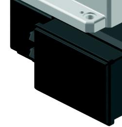
2 Technology that inspires V Speed gradient a Acceleration gradient The modified curved path of the cam allows for a very smooth and harmonic motion. This ensures long life and the shortest possible indexing times. Pos. 1 Pos. 2 Pos. 1 Pos. 2 The customer can rotate the drive 90 downwards, if required. According to your drawing we manufacture high-precision AlMg4,5Mn plates (anodised upon request) and steel plates (nickel-plated upon request). All your equipment can be supplied from one source including a test report. 2 05/2007


. For selecting ring-type rotary indexing tables, please refer to the Electromechanical indexing rings TR/NR brochure.")
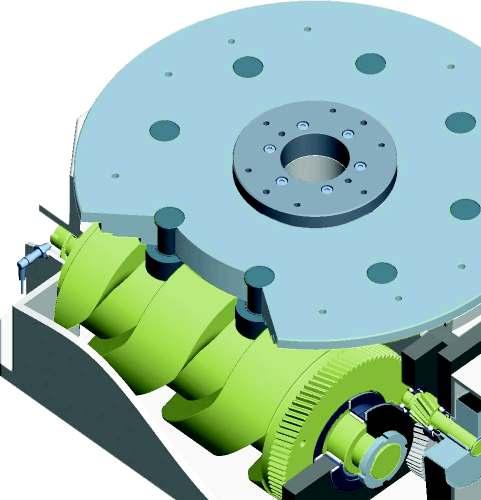
3 Please download the selected rotary indexing table from (in 2D or 3D) directly into your CAD drawing. This will ensure you are using the latest model. Advantages at a glance Strong stationary centre section Large centre boring Specially designed oil and dust seals Precision heavy-duty needle roller bearings. Cam followers with needle roller bearings Housing made of cast iron Rotating section with hardened bearing surface and untreated top surface to enable drilling/tapping 20 % faster EPS electronic overload protection EWR electronic wear reduction By using our control card under normal conditions, the service life of the brake increases by 3 times (EWR). For selecting ring-type rotary indexing tables, please refer to the Electromechanical indexing rings TR/NR brochure. We offer tailor-made electrical componen, e.g. control cards, electronic contactors or frequency inverters. Please contact your representative for further information. 05/2007 3

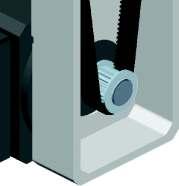
4 4 years guarantee * 1st reason Wear and tear We do not use any friction bearings, all bearings are antifrictional, running in oil. Our plate cam followers are fitted with needle roller bearings, this ensures that we can guarantee full precision, even after 30 million indexing motions. 2nd reason Sophisticated construction We manufacture our drive cam followers as large as possible, this ensures that we use the total length of the cam. For example on our 6-station unit we have 3 or 4 followers engaged with the cam at the same time, these followers are evenly distributed between the acceleration and deceleration forces. 3rd reason Thermal expansion Our cam consis of highly tempered, surface hardened steel and our housing is cast iron. The coefficient of thermal expansion is the same for steel and cast iron. When the housing expands due to the thermal influences, the cam centre - the area where positioning takes place - remains in exactly the same position due to the cam expanding by the same amount. This is different with aluminium housings, which are partly used by our competitors. In these circumstances the housing expands more than the cam. This resul in the plate turning and noticeably leaving i original position! Example: TC 320 T L1 = 96 mm L2 = 145,5 mm T = 20 C A plate diameter of 1200 mm with an aluminium housing and a temperature difference of 20 C would register a counter clockwise positional variation of mm on the circumference. 4 05/2007

5 Technology that inspires Design, production, installation and sales all have one common goal: to supply you with a rotary indexing table with the highest precision that keeps on running and running and running... 4th reason Crash / Emergency stop safety The performance of our drive motors are proportioned to suit the size of table, number of stations and the indexing time. Adjustmen can also be made to suit our customers special requiremen. Too little performance will result in large acceleration values during the deceleration of the dial plate. Too much performance in the case of a crash resul in breakage or loss of precision. A sensible selection of drive performance ensures that the rotary indexing table will survive a crash without major damage. In order to avoid possible mechanical damage of the indexer during re-start after an e-stop, which occurred during index we recommend using our frequency inverter - controller combination. This soft start device allows the indexer to creep slowly from the indexing phase into dwell without overloading barrel cam, cam followers and bearings. 5th reason Electronic accessories / electronic wear compensation If our rotary indexing table control is used the brake wear is minimised or compensated completely. The rotary indexing table is therefore completely maintenance and wear-free throughout i service life. 6th reason No overloading / long life The following tables list the exact calculations of the permissible load factors for our indexers. These calculations include a safety factor to ensure years of reliable performance during multiple shift applications. If you have an application which requires a higher load bearing capacity than the standard values, then please contact us. 7th reason EPS electronic overload protection (optional) Our additional electronically adjustable overload protection device will react within 4 ms. 8th reason Our attitude Our customer service representatives are looking forward to helping you. 05/2007 5


 Higher indexing precision upon request (at Ø 120 mm) indexing 2-10: ± 0.013 mm indexing 12-20: ± 0.016 mm (at Ø 120 mm) 0.02 mm (at Ø 120 mm) 0.")
6 TC 120G Technical data TC 120G Tool plate diameter: Dial diameter: Direction of rotation: Indexings: Cycle frequency: Voltage: Drive motor: Weight: Mounting position: Indexing precision: Indexing precision in radian measurement: Repeatability: Max. flatness of dial plate: Max. run out: Max. parallelism of rotating plate surface to bottom housing surface: Recommended up to 600 mm 120 mm Clockwise - counter clockwise or reciprocating 2, 4, 5, 6, 8, 10, 12, 16, 20, special incremen upon request Up to 200 cpm, depending on inertia loading and number of stops 230 / 400 V 50 Hz, special voltages upon request kw 22 kg See page 39 (it is possible to fix this unit from the top surface - if required, please request a drawing) Indexing 2-10: ± 45 indexing 12-20: ± 55 (in degree seconds) Higher indexing precision upon request (at Ø 120 mm) indexing 2-10: ± mm indexing 12-20: ± mm (at Ø 120 mm) 0.02 mm (at Ø 120 mm) 0.02 mm 0.02 mm (at Ø 120 mm) 0.04 mm 6 05/2007
 unmachined casting Position: Drive on bottom Cross")

. Limit switch M12x1 max.")

7 TC 120G Dimensions Technology that inspires stationary (The dial plate is 0.5 mm higher than the stationary centre section) unmachined casting Position: Drive on bottom Cross section If you require subsequent drilling work on the indexing table, please request information on permissible drilling depths. The illustrated rotating plate position corresponds to the basic position of the rotary indexing table (Position when delivered). Limit switch M12x1 max. screwing depth 6 mm 98 with self-adjusting brake motor Interference area Interference area Table centre Max. centre line deviation between stationary centre section and dial: ± 250 Max. centre line deviation between dial and indexer housing: ± 130 Note: Please ensure motor and brake are accessible for servicing! Cut out for drive (underside mounting) 05/2007 7
8 TC 120G Load table (In the case of higher loads, please ask us for advice.) Step a b c d e f g Indexing 2 Jmax 4 Jmax 5 Jmax 6 Jmax 8 Jmax 10 Jmax 12 Jmax 16 Jmax 20 Jmax 0,06 0,10 0,15 0,23 0,38 0,41 0,51 0,63 0,78 0,99 0,10 0,19 0,28 0,42 0,66 1,00 1,63 0,24 0,31 0,37 0,46 0,57 0,70 0,89 0,16 0,33 0,47 0,71 1,05 1,69 2,75 0,24 0,31 0,37 0,46 0,57 0,70 0,89 0,23 0,39 0,57 0,86 1,34 2,03 3,30 0,24 0,31 0,37 0,46 0,57 0,70 0,89 0,41 0,85 1,21 1,83 2,69 4,34 7,05 0,24 0,31 0,37 0,46 0,57 0,70 0,89 0,57 0,93 1,33 2,01 3,15 4,76 7,73 0,24 0,31 0,37 0,46 0,57 0,70 0,89 0,47 0,67 1,12 1,82 0,22 0,27 0,34 0,43 0,55 0,86 1,31 2,13 0,22 0,27 0,34 0,43 0,86 1,35 2,05 3,32 0,22 0,27 0,34 0,43 J = max admissible mass inertia loading (kgm 2 ) = cycle time (sec.) The time from signal start to message indexer locked is ms longer than the above cycle time, the exact time will depend on the motor, the speed of PLC and the optimization settings (see page 34). EF - control system for brake wear reduction recommended Load data (for the stationary centre section) perm. tilting moment acting on the centre section perm. radial force acting on the centre section perm. force acting vertically perm. tangential moment 150 Nm on the centre section 3000 N acting on the centre section 120 Nm 2000 N Load data (for the rotary indexing dial plate) perm. tilting moment acting on the locked dial plate perm. radial force acting on the locked dial plate perm. operating force (acting vertically on the locked dial perm. tangential moment 200 Nm plate within the normal Ø) 3300 N acting on the locked dial plate 120 Nm 2000 N 8 05/2007


9 TC 120G Technology that inspires 05/2007 9


10 TC 150T Technical data TC 150T Tool plate diameter: Dial diameter: Direction of rotation: Indexings: Cycle frequency: Voltage: Drive motor: Weight: Mounting position: Indexing precision: Indexing precision in radian measurement: Repeatability: Max. flatness of dial plate: Max. run out: Max. parallelism of rotating plate surface to bottom housing surface: tooling plate clearance hole: Recommended up to 800 mm 150 mm Clockwise - counter clockwise or reciprocating 2, 3, 4, 6, 8, 10, 12, 16, 20, special incremen upon request Up to 210 cpm, depending on inertia loading and number of stops 230 / 400 V 50 Hz, special voltages upon request kw 23 kg See page 39 Indexing 2-12: ± 30 indexing 16-24: ± 45 (in degree seconds) Higher indexing precision upon request (at Ø 150 mm) indexing 2-12: ± mm indexing 16-24: ± mm (at Ø 150 mm) 0.01 mm (at Ø 150 mm) 0.01 mm 0.01 mm (at Ø 150 mm) 0.03 mm Ø 80 mm (min) 10 05/2007
 unmachined casting Position: Drive on bottom If you require")


11 TC 150T Dimensions Technology that inspires stationary (The dial plate is 0.5 mm higher than the stationary centre section) unmachined casting Position: Drive on bottom If you require subsequent drilling work on the indexing table, please request information on permissible drilling depths. The illustrated rotating plate position corresponds to the basic position of the rotary indexing table (Position when delivered). max. screwing depth 8 mm Limit switch M12x1 max. screwing depth 6 mm 98 with self-adjusting brake motor Interference area Interference area * only for indexing step h - j Table centre Max. centre line deviation between stationary centre section and dial: ± 180 Max. centre line deviation between dial and indexer housing: ± 120 Note: Please ensure motor and brake are accessible for servicing! Cut out for drive (underside mounting) 05/
12 TC 150T Load table (In the case of higher loads, please ask us for advice.) Stage a b c d e f g h i j Indexing 2 Jmax 3 Jmax 4 Jmax 6 Jmax 8 Jmax 10 Jmax 12 Jmax 16 Jmax 20 Jmax 24 Jmax 0,09 0,14 0,23 0,35 0,58 1,18 1,93 4,18 0,43 0,53 0,66 0,81 1,03 1,47 1,88 2,76 0,14 0,22 0,35 0,53 0,87 1,78 2,90 6,28 0,43 0,53 0,66 0,81 1,03 1,47 1,88 2,76 0,11 0,23 0,37 0,56 0,75 1,35 2,17 4,47 7,28 15,75 0,25 0,32 0,39 0,47 0,59 0,73 0,93 1,33 1,69 2,49 0,26 0,53 0,76 1,15 1,69 2,73 4,43 9,05 14,72 31,80 0,25 0,32 0,39 0,47 0,59 0,73 0,93 1,33 1,69 2,49 0,46 0,96 1,62 2,46 3,02 5,61 8,71 19,31 31,40 67,90 0,25 0,32 0,39 0,47 0,59 0,73 0,93 1,33 1,69 2,49 0,72 1,42 2,03 3,08 4,72 7,28 11,83 24,10 39,30 84,90 0,25 0,32 0,39 0,47 0,59 0,73 0,93 1,33 1,69 2,49 1,04 1,70 2,44 3,69 5,78 8,74 14,19 29,00 47, ,25 0,32 0,39 0,47 0,59 0,73 0,93 1,33 1,69 2,49 0,55 0,84 1,32 2,00 3,25 6,64 10,80 23,40 0,19 0,23 0,29 0,35 0,45 0,64 0,81 1,20 0,69 1,05 1,65 2,50 4,06 8,30 13,50 29,20 0,19 0,23 0,29 0,35 0,45 0,64 0,81 1,20 0,83 1,27 1,98 3,00 4,88 9,97 16,21 35,10 0,19 0,23 0,29 0,35 0,45 0,64 0,81 1,20 J = max admissible mass inertia loading (kgm 2 ) = cycle time (sec.) The time from signal start to message indexer locked is ms longer than the above cycle time, the exact time will depend on the motor, the speed of PLC and the optimization settings (see page 34). EF - control system for brake wear reduction recommended Load data (for the stationary centre section) perm. tilting moment acting on the centre section perm. radial force acting on the centre section perm. force acting vertically perm. tangential moment 200 Nm on the centre section 3500 N acting on the centre section 150 Nm 2500 N Load data (for the rotary indexing dial plate) perm. tilting moment acting on the locked dial plate 500 Nm perm. operating force (acting vertically on the locked dial plate within the normal Ø) 5500 N perm. tangential moment N* acting on the locked dial plate 150 Nm perm. radial force acting on the locked dial plate 6000 N 12 05/2007

13 TC 150T Technology that inspires 05/


 Higher indexing precision upon request (at Ø 220 mm) Indexing 2-12: ± 0.011 mm. Indexing 16-24: ± 0.016 mm.")
14 TC 220T Technical data TC 220T Tool plate diameter: Dial diameter: Direction of rotation: Indexings: Cycle frequency: Voltage: Drive motor: Weight: Mounting position: Indexing precision: Indexing precision in radian measurement: Repeatability: Max. flatness of dial plate: Max. run out: Max. parallelism of rotating plate surface to bottom housing surface: tooling plate clearance hole: Recommended up to 1100 mm 220 mm Clockwise - counter clockwise or reciprocating 2, 3, 4, 6, 8, 10, 12, 16, 20, 24, 30, 36, special incremen upon request Up to 220 cpm, depending on inertia loading and number of stops 230 / 400 V 50 Hz, special voltages upon request kw 44 kg See page 39 Indexing 2-12: ± 20. Indexing 16-24: ± 30. Indexing 30-36: ± 40 (in degree seconds) Higher indexing precision upon request (at Ø 220 mm) Indexing 2-12: ± mm. Indexing 16-24: ± mm. Indexing 30-36: ± mm (at Ø 220 mm) 0.01 mm (at Ø 220 mm) 0.01 mm 0.01 mm (at Ø 220 mm) 0.03 mm Ø 96 mm (min) 14 05/2007
 Position: Drive on bottom Limit switch M12x1 max. screwing depth 13 mm max.")
 Interference area Interference area Possible varian when using motor size 71: - Belt drive lateral with")


15 TC 220T Dimensions Technology that inspires stationary unmachined casting Dimensions for Motor size 71 (please referto table at page 16) Position: Drive on bottom Limit switch M12x1 max. screwing depth 13 mm max. screw thread depth 10 mm Motor size 63 (terminal housing size depends on motor supplier) Motor size 71: (terminal housing size depends on motor supplier) Interference area Interference area Possible varian when using motor size 71: - Belt drive lateral with raised support for indexer housing - Belt drive on bottom Interference area If you require subsequent drilling work on the indexing table, please request information on permissible drilling depths. The illustrated rotating plate position corresponds to the basic position of the rotary indexing table (Position when delivered). Table centre Max. centre line deviation between stationary centre section and dial: ± 150 Max. centre line deviation between dial and indexer housing: ± 100 Note: Please ensure motor and brake are accessible for servicing! Cut out for drive (underside mounting) 05/
16 TC 220T Load table (In the case of higher loads, please ask us for advice.) Stage b c d e f g h i j k l Indexing 2 Jmax 3 Jmax 4 Jmax 6 Jmax 8 Jmax 10 Jmax 12 Jmax 16 Jmax 20 Jmax 24 Jmax 30 Jmax 36 Jmax 0,15 0,34 0,57 0,73 1,15 1,70 2,77 6,59 8,80 0,35 0,50 0,60 0,67 0,84 1,02 1,30 1,99 2,30 0,18 0,30 0,62 0,92 1,16 1,83 2,68 4,37 10,36 13,82 0,29 0,35 0,50 0,60 0,67 0,84 1,02 1,30 1,99 2,30 0,12 (0,19) 0,24 (0,37) 0,46 (0,69) 1,34 (1,97) 2,38 (3,50) 3,36 (4,61) 6,60 8,36 17,13 31,50 48,50 0,22 0,26 0,32 0,45 0,54 0,61 0,76 0,92 1,17 1,80 2,07 0,31 (0,48) 0,58 (0,87) 1,06 (1,59) 3,05 (4,46) 5,40 (7,45) 7,60 14,64 18,84 26,00 70, ,22 0,26 0,32 0,45 0,54 0,61 0,76 0,92 1,17 1,80 2,07 0,58 (0,87) 1,06 (1,58) 1,92 (2,85) 5,44 (6,92) 9,63 (10,22) 12,82 19,05 29,20 46, ,22 0,26 0,32 0,45 0,54 0,61 0,76 0,92 1,17 1,80 2,07 0,92 (1,37) 1,67 (2,48) 3,01 (4,24) 8,48 (8,4) 12,40 15,23 24,30 35,50 57, ,22 0,26 0,32 0,45 0,54 0,61 0,76 0,92 1,17 1,80 2,07 1,34 (1,96) 2,41 (2,90) 4,29 10,19 14,89 15,73 24,60 35,80 58, ,22 0,26 0,32 0,45 0,54 0,61 0,76 0,92 1,17 1,80 2,07 2,00 2,94 3,69 5,79 8,45 13,73 32,50 43,30 0,22 0,26 0,29 0,37 0,44 0,56 0,86 1,00 3,05 4,47 5,62 8,80 12,83 20,80 49,30 65,80 0,22 0,26 0,29 0,37 0,44 0,56 0,86 1,00 3,67 5,37 6,75 10,56 15,40 25,00 59,20 78,90 0,22 0,26 0,29 0,37 0,44 0,56 0,86 1,00 3,59 5,63 8,21 13,35 31,60 42,20 0,19 0,24 0,29 0,37 0,57 0,65 4,32 6,76 9,89 16,03 37,90 50,60 0,19 0,24 0,29 0,37 0,57 0,65 J = max admissible mass inertia loading (kgm 2 ) = cycle time (sec.) The time from signal start to message indexer locked is ms longer than the above cycle time, the exact time will depend on the motor, the speed of PLC and the optimization settings (see page 34). EF - control system for brake wear reduction recommended Load data (for the stationary centre section) perm. tilting moment acting on the centre section perm. radial force acting on the centre section 300 Nm perm. force acting vertically perm. tangential moment on the centre section 5000 N acting on the centre section 200 Nm 4000 N Load data (for the rotary indexing dial plate) perm. tilting moment acting on the locked dial plate 700 Nm 2100 Nm* perm. operating force (acting vertically on the locked dial plate within the normal Ø) 7500 N perm. tangential moment N* acting on the locked dial plate 200 Nm perm. radial force acting on the locked dial plate 8000 N 16 05/2007
17 TC 220T Technology that inspires 05/

18 TC 320T Technical data TC 320T Tool plate diameter: Dial diameter: Direction of rotation: Indexings: Cycle frequency: Voltage: Drive motor: Weight: Mounting position: Indexing precision: Indexing precision in radian measurement: Repeatability: Max. flatness of dial plate: Max. run out: Max. parallelism of rotating plate surface to bottom housing surface: tooling plate clearance hole: Recommended up to 1400 mm 320 mm Clockwise - counter clockwise or reciprocating 2, 3, 4, 6, 8, 10, 12, 16, 20, 24, 30, 36, special incremen upon request Up to 200 cpm, depending on inertia loading and number of stops 230 / 400 V 50 Hz, special voltages upon request kw 112 kg See page 39 Indexing 2-12: ± 20. Indexing 16-24: ± 30. Indexing 30-36: ± 35 (in degree seconds) Higher indexing precision upon request (at Ø 320 mm) Indexing 2-12: ± mm. Indexing 16-24: ± mm. Indexing 30-36: ± mm (at Ø 320 mm) 0.01 mm (at Ø 320 mm) 0.01 mm 0.01 mm (at Ø 320 mm) 0.03 mm Ø 150 mm (min) 18 05/2007


 * frame size 71")

19 TC 320T Dimensions Technology that inspires stationary unmachined casting Position: Drive on bottom max. screwing depth 15 mm If you require subsequent drilling work on the indexing table, please request information on permissible drilling depths. The illustrated rotating plate position corresponds to the basic position of the rotary indexing table (Position when delivered). Limit switch M12x1 Brake motor (terminal housing size depends on the motor supplier) * frame size 71 Interference area Interference area max. screwing depth 12 mm * only for indexing step h - j Table centre Max. centre line deviation between stationary centre section and dial: ± 130 Max. centre line deviation between dial and indexer housing: ± 80 Cut out for drive Note: Please ensure motor and brake are accessible for servicing! (underside mounting) 05/
20 TC 320T Load table (In the case of higher loads, please ask us for advice.) Stage Indexing 2 Jmax 3 Jmax 4 Jmax 6 Jmax 8 Jmax 10 Jmax 12 Jmax 16 Jmax 20 Jmax 24 Jmax 30 Jmax 36 Jmax a b c d e f g h i j k l m n 2,67 3,39 4,05 5,85 8,29 14,11 20,30 32,40 52,70 69,80 0,61 0,69 0,75 0,89 1,06 1,37 1,64 2,07 2,64 3,04 3,30 4,10 5,19 6,17 8,88 12,53 21,30 30,60 48,70 79, ,54 0,61 0,69 0,75 0,89 1,06 1,37 1,64 2,07 2,64 3,04 2,95 4,59 5,46 6,91 8,92 11,22 13,32 19,05 26,8 45,30 65, ,36 0,42 0,45 0,51 0,57 0,64 0,70 0,83 0,99 1,28 1,53 1,93 2,46 2,83 6,89 9,49 11,25 14,16 18,23 22,90 27,10 38,70 54,40 91, ,36 0,42 0,45 0,51 0,57 0,64 0,70 0,83 0,99 1,28 1,53 1,93 2,46 2,83 12,40 18,97 24,20 30,40 39,10 47,90 58,10 82, ,36 0,42 0,45 0,51 0,57 0,64 0,70 0,83 0,99 1,28 1,53 1,93 2,46 2,83 17,19 22,80 27,00 33,90 43,60 54,60 64,70 92, ,35 0,40 0,44 0,49 0,55 0,62 0,67 0,80 0,95 1,24 1,48 1,87 2,38 2,73 20,70 27,40 32,40 40,70 52,30 65,60 77, ,35 0,40 0,44 0,49 0,55 0,62 0,67 0,80 0,95 1,24 1,48 1,87 2,38 2,73 8,15 10,52 13,23 15,69 22,40 31,50 53,30 76, ,22 0,25 0,28 0,30 0,36 0,42 0,55 0,66 0,83 1,06 1,21 12,29 15,84 19,88 23,60 33,60 47,30 79, ,22 0,25 0,28 0,30 0,36 0,42 0,55 0,66 0,83 1,06 1,21 17,24 21,60 25,60 36,60 51,40 86, ,25 0,28 0,30 0,36 0,42 0,55 0,66 0,83 1,06 1,21 14,16 20,20 28,50 48,10 69, ,20 0,24 0,28 0,37 0,44 0,55 0,70 0,81 17,03 24,30 34,20 57,80 82, ,20 0,24 0,28 0,37 0,44 0,55 0,70 0,81 J = max admissible mass inertia loading (kgm 2 ) = cycle time (sec.) The time from signal start to message indexer locked is ms longer than the above cycle time, the exact time will depend on the motor, the speed of PLC and the optimization settings (see page 34). EF - control system for brake wear reduction recommended Load data (for the stationary centre section) perm. tilting moment acting on the centre section perm. radial force acting on the centre section perm. force acting vertically perm. tangential moment 1800 Nm on the centre section N acting on the centre section 800 Nm N Load data (for the rotary indexing dial plate) perm. tilting moment acting on the locked dial plate 2250 Nm 6750 Nm* perm. operating force (acting vertically on the locked dial plate within the normal Ø) N perm. tangential moment N* acting on the locked dial plate 600 Nm perm. radial force acting on the locked dial plate N *strengthened version on demand 20 05/2007


21 TC 320T Dimensions Technology that inspires 05/


22 TC 500T Technical data TC 500T Tool plate diameter: Dial diameter: Direction of rotation: Indexings: Cycle frequency: Voltage: Drive motor: Weight: Mounting position: Indexing precision: Indexing precision in radian measurement: Repeatability: Max. flatness of dial plate: Max. run out: Max. parallelism of rotating plate surface to bottom housing surface: tooling plate clearance hole: Recommended up to 2000 mm 500 mm Clockwise - counter clockwise or reciprocating 2, 3, 4, 6, 8, 10, 12, 16, 20, 24, 30, 36, 48, special incremen upon request Up to 180 cpm, depending on inertia loading and number of stops 230 / 400 V 50 Hz, special voltages upon request kw 305 kg See page 39 Indexing 2-12: ± 15. Indexing 16-48: ± 20 (in degree seconds) Higher indexing precision upon request (at Ø 500 mm) Indexing 2-12: ± mm. Indexing 16-48: ± mm (at Ø 500 mm) mm (at Ø 500 mm) mm mm (at Ø 500 mm) 0.03 mm Ø 242 mm (min) 22 05/2007


23 TC 500T Dimensions Technology that inspires stationary unmachined casting Position: Drive on bottom max. screwing depth 18 mm max. screwing depth 12 mm Limit switch M12x1 Brake motor (terminal housing size depends on the moto supplier * frame size 71 Interference area Interference area If you require subsequent drilling work on the indexing table, please request information on permissible drilling depths. The illustrated rotating plate position corresponds to the basic position of the rotary indexing table (Position when delivered). Table centre Max. centre line deviation between stationary centre section and dial: ± 75 Max. centre line deviation between dial and indexer housing: ± 55 Note: Please ensure motor and brake are accessible for servicing! Cut out for drive (underside mounting) 05/
24 TC 500T Load table (In the case of higher loads, please ask us for advice.) Stage Indexing 2 Jmax 3 Jmax 4 Jmax 6 Jmax 8 Jmax 10 Jmax 12 Jmax 16 Jmax 20 Jmax 24 Jmax 30 Jmax 36 Jmax 48 Jmax a b c d e f g h i j k l m n 4,80 8,90 11,20 15,90 20,70 29,50 44,50 71, ,68 0,79 0,87 1,02 1,16 1,36 1,66 2,10 2,67 3,02 3,26 4,28 7,80 10,90 13,70 19,30 25,00 35,50 53,50 86, ,68 0,79 0,87 1,02 1,16 1,36 1,66 2,10 2,67 3,02 3,26 4,28 7,10 10,10 16,00 22,00 27,10 37,80 48,60 68, ,43 0,50 0,61 0,71 0,79 0,92 1,04 1,23 1,50 1,89 2,41 2,72 2,93 3,85 14,70 22,20 33,80 46,00 56,30 77,90 99, ,43 0,50 0,61 0,71 0,79 0,92 1,04 1,23 1,50 1,89 2,41 2,72 2,93 3,85 34,20 47,40 71,30 96, ,43 0,50 0,61 0,71 0,79 0,92 1,04 1,23 1,50 1,89 2,41 2,72 2,93 3,85 43,10 59,70 89, ,43 0,50 0,61 0,71 0,79 0,92 1,04 1,23 1,50 1,89 2,41 2,72 2,93 3, , ,43 0,50 0,61 0,71 0,79 0,92 1,04 1,23 1,50 1,89 2,41 2,72 2,93 3,85 19,80 27,20 33,50 46,50 59,70 83, ,27 0,32 0,35 0,41 0,46 0,55 0,67 0,84 1,07 1,21 1,30 1,71 31,80 43,40 53,10 73,50 94, ,27 0,32 0,35 0,41 0,46 0,55 0,67 0,84 1,07 1,21 1,30 1,71 38,50 52,40 64,10 88, ,27 0,32 0,35 0,41 0,46 0,55 0,67 0,84 1,07 1,21 1,30 1,71 34,90 48,50 62,30 87, ,23 0,27 0,31 0,36 0,44 0,56 0,71 0,80 0,87 1,14 34,20 47,60 61,10 85, ,23 0,27 0,31 0,36 0,44 0,56 0,71 0,80 0,87 1,14 46,20 64,00 81, ,23 0,27 0,31 0,36 0,44 0,56 0,71 0,80 0,87 1,14 J = max admissible mass inertia loading (kgm 2 ) = cycle time (sec.) The time from signal start to message indexer locked is ms longer than the above cycle time, the exact time will depend on the motor, the speed of PLC and the optimization settings (see page 34). EF - control system for brake wear reduction recommended Load data (for the stationary centre section) perm. tilting moment acting on the centre section perm. radial force acting on the centre section perm. force acting vertically perm. tangential moment 2500 Nm on the centre section N acting on the centre section 1100 Nm N Load data (for the rotary indexing dial plate) perm. tilting moment acting on the locked dial plate 6000 Nm Nm* perm. operating force (acting vertically on the locked dial plate within the normal Ø) N perm. tangential moment N* acting on the locked dial plate 1000 Nm perm. radial force acting on the locked dial plate N *strengthened version on demand 24 05/2007
25 TC 500T Technology that inspires 05/


26 TC 700T Technical data TC 700T Tool plate diameter: Dial diameter: Direction of rotation: Indexings: Cycle frequency: Voltage: Drive motor: Weight: Mounting position: Indexing precision: Indexing precision in radian measurement: Repeatability: Max. flatness of dial plate: Max. run out: Max. parallelism of rotating plate surface to bottom housing surface: tooling plate clearance hole: Recommended up to 3000 mm 700 mm Clockwise - counter clockwise or reciprocating 2, 3, 4, 6, 8, 10, 12, 16, 20, 24, 30, 36, 48, 60, special incremen upon request Up to 120 cpm, depending on inertia loading and number of stops 230 / 400 V 50 Hz, special voltages upon request kw, frame size 80/90/ kg See page 39 Indexing 2-12: ± 12. Indexing 16-60: ± 16 (in degree seconds) Higher indexing precision upon request (at Ø 700 mm) Indexing 2-12: ± mm. Indexing 16-60: ± mm (at Ø 700 mm) mm (at Ø 700 mm) mm mm (at Ø 700 mm) 0.03 mm Ø 242 mm (min) 26 05/2007


27 TC 700T Dimensions Technology that inspires stationary unmachined casting Position: Drive on bottom max. screwing depth 22 mm max. screwing depth 15 mm Limit switch M12x1 Brake motor (terminal housing size depends on the moto supplier * frame size 71 Interference area Interference area If you require subsequent drilling work on the indexing table, please request information on permissible drilling depths. The illustrated rotating plate position corresponds to the basic position of the rotary indexing table (Position when delivered). Table centre Max. centre line deviation between stationary centre section and dial: ± 60 Max. centre line deviation between dial and indexer housing: ± 40 Note: Please ensure motor and brake are accessible for servicing! Cut out for drive (underside mounting) 05/
28 TC 700T Load table (In the case of higher loads, please ask us for advice.) Stage Indexing 2 Jmax 3 Jmax 4 Jmax 6 Jmax 8 Jmax 10 Jmax 12 Jmax 16 Jmax 20 Jmax 24 Jmax 30 Jmax 36 Jmax 48 Jmax 60 Jmax s a b c d e f g h i j k l ,69 0,81 0,98 1,14 1,46 1,69 1,96 2,40 3,01 3,84 4,70 6, ,69 0,81 0,98 1,14 1,46 1,69 1,96 2,40 3,01 3,84 4,70 6, ,53 0,62 0,73 0,88 1,03 1,31 1,52 1,76 2,16 2,71 3,45 4,23 5, ,53 0,62 0,73 0,88 1,03 1,31 1,52 1,76 2,16 2,71 3,45 4,23 5, ,53 0,62 0,73 0,88 1,03 1,31 1,52 1,76 2,16 2,71 3,45 4,23 5, ,53 0,62 0,73 0,88 1,03 1,31 1,52 1,76 2,16 2,71 3,45 4,23 5, ,53 0,62 0,73 0,88 1,03 1,31 1,52 1,76 2,16 2,71 3,45 4,23 5, ,46 0,58 0,67 0,78 0,96 1,20 1,53 1,88 2, ,46 0,58 0,67 0,78 0,96 1,20 1,53 1,88 2, ,46 0,58 0,67 0,78 0,96 1,20 1,53 1,88 2, ,39 0,45 0,52 0,64 0,80 1,02 1,25 1, ,39 0,45 0,52 0,64 0,80 1,02 1,25 1, ,39 0,45 0,52 0,64 0,80 1,02 1,25 1, ,39 0,45 0,52 0,64 0,80 1,02 1,25 1,65 J = max admissible mass inertia loading (kgm 2 ) = cycle time (sec.) The time from signal start to message indexer locked is ms longer than the above cycle time, the exact time will depend on the motor, the speed of PLC and the optimization settings (see page 34). EF - control system for brake wear reduction recommended Load data (for the stationary centre section) perm. tilting moment acting on the centre section 3000 Nm 5000 Nm* perm. force acting vertically on the centre section N perm. tangential moment N* acting on the centre section 1400 Nm perm. radial force acting on the centre section N Load data (for the rotary indexing dial plate) perm. tilting moment acting on the locked dial plate Nm Nm* perm. operating force (acting vertically on the locked dial plate within the normal Ø) N perm. tangential moment N* acting on the locked dial plate 1700 Nm perm. radial force acting on the locked dial plate N *strengthened version on demand 28 05/2007


29 TC 700T Technology that inspires 05/

30 TC 1000T Technical data TC 1000T Tool plate diameter: Dial diameter: Direction of rotation: Indexings: Cycle frequency: Voltage: Drive motor: Weight: Mounting position: Indexing precision: Indexing precision in radian measurement: Repeatability: Max. flatness of dial plate: Max. run out: Max. parallelism of rotating plate surface to bottom housing surface: tooling plate clearance hole: Recommended up to 5000 mm 1000 mm Clockwise - counter clockwise or reciprocating 2, 3, 4, 6, 8, 10, 12, 16, 20, 24, 32, special incremen upon request Up to 60 cpm, depending on inertia loading and number of stops 230 / 400 V 50 Hz, special voltages upon request kw, frame size kg See page 39 Indexing 2-20: ± 12. Indexing 24-32: ± 16 (in degree seconds) Higher indexing precision upon request (at Ø 1000 mm) Indexing 2-20: ± mm. Indexing 24-32: ± mm (at Ø 1000 mm) 0.03 mm (at Ø 1000 mm) 0.03 mm 0.03 mm (at Ø 1000 mm) 0.05 mm Ø 522 mm (min) 30 05/2007


31 TC 1000T Dimensions Technology that inspires stationary unmachined casting Motor fan cover (internal motor) max. screwing depth 15 mm If you require subsequent drilling work on the indexing table, please request information on permissible drilling depths. The illustrated rotating plate position corresponds to the basic position of the rotary indexing table (Position when delivered). max. screwing depth 24 mm Limit switch M12x1 Motor connections Interference area Centre line deviation between stationary centre section and dial plate: ± 45 Centre line deviation between dial plate and indexer housing: ± 35 Note: Please ensure motor and brake are accessible for servicing! 05/
32 TC 1000T Load table (In the case of higher loads, please ask us for advice.) Stage a b c d e f g h i Indexing 2 Jmax 3 Jmax 4 Jmax 6 Jmax 8 Jmax 10 Jv 12 Jmax 16 Jmax 20 Jmax 24 Jmax 32 Jmax 36 Jmax 72 Jmax ,28 1,50 1,92 2,57 3,15 3,96 5,04 6,18 10, ,28 1,50 1,92 2,57 3,15 3,96 5,04 6,18 10, ,15 1,35 1,73 2,32 2,84 3,56 4,54 5,56 9, ,15 1,35 1,73 2,32 2,84 3,56 4,54 5,56 9, ,15 1,35 1,73 2,32 2,84 3,56 4,54 5,56 9, ,15 1,35 1,73 2,32 2,84 3,56 4,54 5,56 9, ,15 1,35 1,73 2,32 2,84 3,56 4,54 5,56 9, ,15 1,35 1,73 2,32 2,84 3,56 4,54 5,56 9, ,51 0,60 0,77 1,03 1,26 1,58 2,02 2,47 4, ,51 0,60 0,77 1,03 1,26 1,58 2,02 2,47 4, ,51 0,60 0,77 1,03 1,26 1,58 2,02 2,47 4, ,51 0,69 0,84 1,06 1,34 1,65 2, ,51 0,69 0,84 1,06 1,34 1,65 2,86 J = max admissible mass inertia loading (kgm 2 ) = cycle time (sec.) The time from signal start to message indexer locked is ms longer than the above cycle time, the exact time will depend on the motor, the speed of PLC and the optimization settings (see page 34). EF - control system for brake wear reduction recommended Load data (for the stationary centre section) perm. tilting moment acting on the centre section perm. radial force acting on the centre section perm. force acting vertically perm. tangential moment 5000 Nm on the centre section N acting on the centre section 1800 Nm N Load data (for the rotary indexing dial plate) perm. tilting moment acting on the locked dial plate Nm Nm* perm. operating force (acting vertically on the locked dial plate within the normal Ø) N perm. tangential moment N* acting on the locked dial plate 2200 Nm perm. radial force acting on the locked dial plate N *strengthened version on demand 32 05/2007
33 TC 1000T Technology that inspires 05/
34 Control card TS 004E Advantages User friendly push buttons on front panel. Easy to optimize the cycle time of the indexer. Various monitor functions help to avoid crashes. Motor protection through cycle time monitoring. Allows failure analysis by telephone. EWR: Considerable extension of the service life of the brake by reduction of the motor speed before braking Tes Interference emissions: EN Interference resistance: EN Requiremen in accordance with EC directive for electromagnetic compatibility (EMC) 89/336/EEC Installation options In a 19 rack (in conjunction with terminal PCB TS 004 K1) In the PCB holder In the protective housing Dimensions (L x W x H) Control card: Eurocard 100 x 160 mm Front plate 3HE/8TE Multipoint plug, 64-pin in accordance with DIN Type B PCB holder: 220 x 130 x 50 mm Housing for rear wall mounting: 235 x 135 x 67 mm Housing for rail mounting: 245 x 135 x 67 mm Housing for front panel installation: 235 x 135 x 67 mm Installation opening: 136 x 68 mm TS 004E Terminal PCB TS 004K1 Control card TS 004E Start Stop / Reset PCB holder Stop / Delay Table in position Table rotating Return Short circuit Motor overload Pos. overrun Protective housing ** for: Rear wall mounting Front panel mounting Rail mounting Release brake Step Automat ** All protective housings are also available with a lockable, transparent front door. The installation depth is then increased by 21 mm. * Note on switching times The actual measured rotation time (from the start signal to the electrical in-position signal) comprises the calculated rotation motion time given in the tables and type-related delays. An important factor are electrical signal processing times, input filters, mechanical motor idle times and also the setting and optimization of the ideal starting position (please refer to the TC-T operating instructions) /2007
35 Circuit diagram TS 004E Brake motor (normal operation) Technology that inspires TS 004 K1 emergency stop circuit electronic motor contactor M T motor brake limit switch Brake motor (reciprocating operation) TS 004 K1 emergency stop circuit Electronic reversing motor contactor motor brake limit switch 05/
 Reduced speed during start up Variable acceleration and deceleration ramps No brake wear and tear,")
36 Control card EF xxx-x Advantages The controller EF combines the advantages of the TS 004 E with additional features of a modern frequency inverter. Soft restart after e-stop because of reducing the starting momentum (refer to page 5 - reason 4) Reduced speed during start up Variable acceleration and deceleration ramps No brake wear and tear, brake is activated in e-stop only Fine adjustment of index speed up to 50 Hz Allows single-phase 230 VAC operation up to 0.25 KW motor power The frequency inverter is preprogrammed Operation menus in various languages Shortest start up Motor protection through cycle time monitoring Monitoring of operational data Allows failure analysis by telephone No motor contactor necessary Tes Interference emissions: EN (radio disturbance characteristics) from 1991 Requiremen in accordance with EN from 1993 Limit value class A in accordance with EN Interference resistance: ENV radio disturbance immunity from 8/93 ENV conducted disturbances induced by radio-frequency fields from 8/93 EN ESD from 1996 EN BURST from 1996 EN voltage variations from 1995 (limit values and requiremen in accordance with EN from 1995) Insulation resistance: Over-voltage category III in accordance with VDE 0110 Type de protection: IP20 UL listed Installation dimensions and weigh (The devices are supplied on a mounting plate) Model EF 037/1-1.0 EF 150/3-1.0 EF 220/3-1.0 EF 300/3-1.0 Width: 160 mm 160 mm 160 mm 200 mm Length: 250 mm 330 mm 330 mm 345 mm Depth: 180 mm 180 mm 180 mm 180 mm Weight: 2.15 kg 3.25 kg 3.25 kg 4.4 kg 36 05/2007
37 Circuit diagram EF xxx-x Single phase version (EF 037/1) Technology that inspires 24V 24V EMERGENCY STOP circuit GND - + Position sensor A CW/CCW Start (level) Start (edge) /Reset Mode 2 Parameter record 3 ignor. Parameter record 2 Reset Error L1 N PE I O24 +O24-24 VBr I4 I5 I6 I8 I9 I11 I12 I X1.1 L1 N PE PLC CAN L CAN H 24V GND CAN H CAN L Frequency inverter CAN GND 7 O1 O2 O3 O5 O6 O7-24 O9 X2.1 U V W PE EMERGENCY STOP circuit Table in pos. Start permitted Automatic A ik Overload Ü Pos. exceeded Sum Fault PE max. 1 A output current B- B+ U V W PE Three-phase version (EF 150/3, EF 220/3, EF 300/3) 24V 24V EMERGENCY STOP circuit GND L1 L2 L3 M 3 Delta connection - + Position sensor A CW/CCW Start (level) Start (edge) /Reset Mode 2 Parameter record 3 ignor. Parameter P record 2 Reset R Error PE I O24 +O24-24 VBr I 4 I5 I6 I8 I9 I11 I12 I X1.1 L1 L2L3 PE PLC CAN H CAN L 24V GN D CANH CANL Frequency inverter CAN GND 7 O1 O2 O3 O5 O6 O7-24 O9 X2.1 U V W PE BR1 BR2 EMERGENCY STOP circuit *Option brake resistance Table in pos. Start permittedg Automatic Overload Pos. exceeded Sum Fault PE max. 1 A output current B- B+ U V W PE M 3 Star connection 05/
38 Calculation Indexing precision as a factor of Ø Ø mm Nominal indexing precision = ± 20 D = Pitch circle diameter T g = Brochure precision x D x T g 360 x radian measure in µm Accuracy of circular run out for additional plates Diameter (mm) < 600 < 800 < 1100 < 1400 < 1800 < 2500 Thickness (mm) > 20 < 20 > 20 < 20 > 20 < 20 > 25 < 25 > 25 < 25 > 30 < 30 Flatness Quality A (mm) Flatness Quality B (mm) If we machine your additional tooling plate, ± 3 needs to be added to the above value, in order to determine the precise indexing accuracy. Additional indexing plates We manufacture additional steel or aluminium indexing plates according to your specification. The material AlMg4.5F28 is aged for at least 3 months before it is used in production. Upon request, aluminium plates can be anodized (natural) and steel plates can be nickel plated or finished in colour brown. For detailed information on additional plates, please refer to our Electromechanical Indexing Machine Bases brochure. Calculation of the mass inertia momentum Solid body: Individual weigh (approximation formula): J = 0.5 x r a 2 x m a or J = x m a x D a 2 r a D a J = 1.1 x r e 2 x m e x n r e m m r a = radius in m m a = mass (weight) in kg D a = diameter in m r e = radius in m m e = mass (weight) in kg n = number of fixtures 38 05/2007
39 Fax-No. Weiss GmbH: +49 (0) Machine Dimensioning TC Request Enclosure of order Technology that inspires Dear Customer, Thank you for your interest in our TC rotary indexing tables. To ensure we supply the correct unit for your application, we kindly ask you to answer the following questions: Model Permissible installation positions TC 120G TC 150T TC 220T TC 220T with motor size 71 TC 320T TC 500T TC 700T TC 1000T No. of stations normal overhead vertical (belt drive on the right) Position of the drive motor vertical (belt drive below) Standard colour RAL 7035 (light grey) Special colour RAL (extra charge) lateral inside lateral ouide Motor below inside Motor below ouide Calculation of the mass total mass inertia momentum The following specifications of the tooling plate are extremely important to establish the shortest possible indexing time of your TC table (calculation according to the formula on page 38): Additional indexing plate Included in offer and delivery Do not supply Diameter: mm Thickness: mm Material Al St other Workpiece and fixture: No. of stations: Weight per station Centre of gravity diameter: kg mm Based on the calculated mass inertia, do you want: the shortest possible indexing time a longer indexing time of sec Electrical data Index frequency: Cycles / min* (at an indexing frequency of more than 50/min we recommend the use of the EF control card) Drive Motor Connection voltage x 400 V / 50 Hz (Standard) other: V / Hz Brake Brake voltage 24 V = (recommended) other: V It is recommended to drive the motor with an electronic contactor! Electronic contractor (not necessary with controller EF) Electronic reversing contactor (not necessary with controller EF) Control Controller EF (frequency inverter) (included in delivery of TC 700T and TC 1000T) WEISS Control card TS 004 E Terminal PCB for 19 rack PCB card holder Protective housing for: Rear wall mounting Front panel mounting Rail mounting Front door, lockable and transparent Front panel language for WEISS Control card TS 004 E German Italian English French Dutch Czech For technical enquiries Company: Name: Department: 05/2007 Desired delivery date: Phone: Fax: 39


40 Technology that inspires Rotary Indexing Tables TC Rotary Indexing Rings TR/NR Numeric Controlled Heavy Duty Indexing Ring CR Numeric Controlled Indexing Tables NC Torque Motor TO Compact model Torque Motor TO Ring construction Handling device HP 140 Flexible Assembly Machine Pick-o-Mat Side loading rotary unit TH Fast Cycling Linear Assembly System LS 280 Indexing Machine Bases SR/SK Additional indexing plate We reserve the right to change or discontinue specifications without prior notice WEISS GmbH Sondermaschinentechnik Siemensstraße 17 D Buchen Fon +49(0) Fax +49(0) info@weiss-gmbh.de WEISS 05/2007 TC
TC ROTARY INDEXING TABLE: RELIABILITY FOR A LIFETIME
 TC FIXED-STATION ROTARY INDEXING TABLES TC ROTARY INDEXING TABLE TC ROTARY INDEXING TABLE: RELIABILITY FOR A LIFETIME EXTENDED WARRANTY Using our rotary table control system minimises brake wear. This
Additional Indexing Plates Indexing Machine Bases. Technology that inspires
 Additional Indexing Plates Indexing Machine Bases Technology that inspires Everything from one source Base plate / indexing machine bases / system components: Basic idea Standing and rotating add-ons Systems
Technology that inspires. Mechanics Software Electronics. Excerpt of the WEISS Product Range. Nr rotary indexing ring freely programmable
 Technology that inspires Product Range Mechanics Software Electronics Excerpt of the WEISS Product Range Nr rotary indexing ring freely programmable The WEISS range at a glance 4 I would like to commission
Technology that inspires. Product. Mechanics Software Electronics. Excerpt of the WEISS Product Range
 Technology that inspires Product Range Mechanics Software Electronics Excerpt of the WEISS Product Range Customer specific solutions The WEISS range at a glance 4 I would like to commission my installation
PRODUCT RANGE. NR ROTARY INDEXING RING freely programmable. Excerpt of the WEISS Product Range. Mechanics Software Electronics
 Technology that inspires PRODUCT RANGE Mechanics Software Electronics Excerpt of the WEISS Product Range NR ROTARY INDEXING RING freely programmable The WEISS range at a glance 4 I would like to commission
Technology that inspires PRODUCT RANGE. Mechanics Software Electronics. Excerpt of the WEISS Product Range
 Technology that inspires PRODUCT RANGE Mechanics Software Electronics Excerpt of the WEISS Product Range CUSTOMER SPECIFIC SOLUTIONS The WEISS range at a glance 4 I would like to commission my installation
Absolute Encoders - Singleturn
 The Sendix 5853 and Sendix 5873 singleturn encoders with SSI or BiSS interface and optical sensor technology can achieve a resolution of max. 7 bits. These encoders are also available with an optional
RoHS. High shaft load capacity. Shock / vibration resistant
 Due to their sturdy bearing construction in Safety Lock Design, the Sendix 5000 and 5020 offer high resistance against vibration and installation errors. The rugged housing, high protection level of up
CI-tronic Soft start motor controller
 Data sheet CI-tronic Soft start motor controller MCI 3, MCI 15, MCI, MCI 30 I-O, MCI 40-3D I-O and MCI 50-3 I-O The MCI soft starters are designed for soft starting and stopping of 3 phase AC motors, thus
Instruction manual for STA 1 sectional door operator
 Instruction manual for STA 1 sectional door operator Sectional door operator STA 1 / Rev. 0.3 1 GB 1. Contents 3. General safety instructions 1. Contents 2 2. Key to symbols 2 3. General safety instructions
LENORD. +BAUER... automates motion. GEL 2351 with current or voltage interface. Technical information Version General. Features.
 GEL 2351 with current or voltage interface LENORD +BAUER... automates motion. Technical information Version 201-11 General Single turn absolute rotary encoder with a resolution of 16 bits Magneto-resistive
Product Information ECI 1319S EQI 1331S. Absolute Rotary Encoders without Integral Bearing and with DRIVE-CLiQ Interface.
 Product Information ECI 1319S EQI 1331S Absolute Rotary Encoders without Integral Bearing and with DRIVE-CLiQ Interface Firmware 15 12/2018 ECI 1319S, EQI 1331S Rotary encoders for absolute position values
EC centrifugal fan. backward curved, single inlet
 RG4-AM56- ebm-papst Mulfingen GmbH & Co. KG Bachmühle 746 Mulfingen Phone: +49 8 8- Fax: +49 8 8- www.ebmpapst.com info@de.ebmpapst.com Nominal data Type Motor RG4-AM56- MG-EA Phase ~ Nominal voltage [VAC]
The ZSH stepper motor convinces with its robust housing with high-strength cable gland. The motor is waterproof up to 10 m with the IP68 option.
 /ZSH HRSH ZSH Stepper otor Robust. Powerful. Reliable. Phytron s HRSHEnvironment motors are particularly suitable for challenging applications in mechanical engineering and industry. Challenging conditions
T22. Torque transducer. Special features. Data sheet
 T22 Torque transducer Special features - Nominal (rated) torques 0.5 Nm, 1 Nm, 2 Nm, 5 Nm, Nm, Nm, 50 Nm, 0 Nm, 0 Nm, 500 Nm and 1 knm - Nominal (rated) rotational speed up to 000 rpm (depending on measuring
PTC-resistor relay type MS 220 K and MSR 220 K PTC-resistor trip device
 MINIPAN digital panel meters, temperature- and mains controlling, special purpose instruments for customer requirements www.ziehl.com Operating manual PTC-resistor relay type MS 220 K and MSR 220 K PTC-resistor
EC 45 flat with integrated electronics Document ID: en Operating Manual
 EC 45 flat with integrated electronics Document ID: 919801en Operating Manual Edition June 2017 The EC 45 flat with integrated electronics is a brushless, speed-controlled 1-quadrant drive. It is available
Absolute Encoders Multiturn
 Absolute Encoders Multiturn Functional Safety, optical The absolute multiturn encoders Sendix 5863 SIL and 5883 SIL are perfectly suited for use in safety-related applications up to SIL3 according to DIN
Instruction manual for STA 1 sectional door operator
 Instruction manual for STA 1 sectional door operator GB Sectional door operator STA 1 / Rev. 0.0 1 1. Contents 3. General safety instructions 1. Contents 2 2. Key to symbols 2 3. General safety instructions
Product Information. ERN 1085 Incremental Rotary Encoder with Z1 Track
 Product Information ERN 1085 Incremental Rotary Encoder with Z1 Track 02/2018 ERN 1085 Rotary encoder with mounted stator coupling Compact dimensions Blind hollow shaft 6 mm Z1 track for sine commutation
Roller Guides C-Rail Systems Linear Guide Systems Ball-Bearing Guide Bushes Ball-bush block guides Shafts Accessories for Linear Slides
 Roller Guides C-Rail Systems Linear Guide Systems Ball-Bearing Guide Bushes Ball-bush block guides Shafts Accessories for Linear Slides Application example linear systems, drives and accessories 1 2 3
Outside Temperature Sensors
 1 814 1814P01 Symaro Outside Temperature Sensors QAC31 Active sensors for acquiring the outside temperature Operating voltage AC 24 V or DC 13535 V Signal output DC 010 V or 420 ma Use The QAC31 outside
LENORD. +BAUER... automates motion. GEL 2037 with heavy duty flange or tooth wheel adapter. Technical information Version General.
 GEL 2037 with heavy duty flange or tooth wheel adapter LENORD +BAUER... automates motion. Technical information Version 2014-07 General Multiturn absolute rotary encoders with a resolution of up to 25
Data Sheet for Angle Sensors
 ETA25PM - R ETA25PM - F ETA25PM - TS 10 to 100-times longer life compared with multiturn potentiometers Free user programmable start and end position (electrical angle 10 up to 72000 ) Simple user programming
Torque Sensor Series 3000 and Series 4000
 Properties Sensorshaft with integrated torque and angle measurement Non-contact measurement system, high robustness Plug & Play solution, no additional electronics required Performance Measurement range
References 1 for asynchronous motors 1
 References 1 DF56902 DF5690 DF56901 ATS 01N10FT ATS 01N212QN ATS 01N20LY for 0.7 to kw motors power Nominal current Reference (2) Weight Single phase -phase 20 V 210 V 20 V 20 V 400 V 460 V kw HP kw HP
EC centrifugal fan. backward curved, single inlet
 RG56-AG7- ebm-papst Mulfingen GmbH & Co. KG Bachmühle 746 Mulfingen Phone: +49 798 - Fax: +49 798 - www.ebmpapst.com info@de.ebmpapst.com Nominal data Type Motor RG56-AG7- MG-FF Phase ~ Nominal voltage
XXXX e. X d.. X X X a
 The Heavy uty incremental encoder type 0H boasts a high degree of ruggedness in a very compact design. Its special construction makes it perfect for all applications in very harsh environments. / RoHS
SPIETH Locknuts. Series MSW. Works Standard SN 04.03
 SPIETH Locknuts Series MSW Works Standard SN 0.03 SPIETH Locknuts Series MSW SPIETH locknuts offer a range of technical benefits, qualified by their special system and production. Under high levels of
Installation and Operational Instructions for ROBA -switch Type 017._00.2
 OBA -switch Type 017._00.2 Guidelines on the Declaration of Conformity A conformity evaluation has been carried out for the product in terms of the EC Low Voltage Directive 2014/35/ EC and the EMC Directive
Product Information. EQN 1337 F Absolute Rotary Encoder with Tapered Shaft for Fanuc Controls with i Interface
 Product Information EQN 1337 F Absolute Rotary Encoder with Tapered Shaft for Fanuc Controls with i Interface 11/2017 EQN 1337 F Rotary encoders for absolute position values Installation diameter 65 mm
Adjustable Feet Castors Accessories for Floor Elements
 Adjustable Feet Castors Accessories for Floor Elements Products in this section Levelling Knuckle Feet Threaded spindles for infinite height adjustment Metal or plastic foot plate Knuckle Feet X Compatible
Wind Transmitter First Class
 THE WORLD OF WEATHER DATA - THE WORLD OF WEATHER DATA - THE WORLD OF WEATHER DATA Instruction for Use 021310/07/06 Wind Transmitter First Class 4.3350.00.000 4.3350.10.000 ADOLF THIES GmbH & Co. KG Hauptstraße
NEWS Part. N /0 MINITEC NEWS
 NEWS 2009 Part. N 95.0423/0 MINITEC NEWS 2009 1 TABLE OF CONTENT INTRODUCTION CONTENTS 3 END CAP Z WITH HAMMER TAPS 3 END CAP 45X45 VA 4 ANGLE 25 GD-Z 4 ANGLE 45X90 GD-Z 5 ANGLE 90 GD-Z 5 HINGE 19 S 6
Product Information. RCN 2000 RCN 5000 RCN 8000 Absolute Angle Encoders for Safety-Related Applications
 Product Information RCN 2000 RCN 5000 RCN 8000 Absolute Angle Encoders for Safety-Related Applications September 2013 RCN 2000 series Absolute angle encoders for safety-related applications Safe absolute
Catalog 200 Contactors up to 115 A Motor Starters up to 55 kw 03/2009
 Catalog 00 Contactors up to 5 A Motor Starters up to 55 kw 03/009 Kraus & Naimer The development of the Blue Line rotary switch, contactor and motor starter product ranges is based on more than hundred
LENORD. +BAUER... automates motion. Magnetic absolute rotary encoder GEL 2037 with heavy duty flange or tooth wheel adapter
 Magnetic absolute rotary encoder GEL 2037 with heavy duty flange or tooth wheel adapter LENORD +BAUER... automates motion. Technical information Version 01.12 General Multiturn absolute rotary encoders
EC centrifugal fan. backward curved, single inlet
 RG6-AB6- ebm-papst Mulfingen GmbH & Co. KG Bachmühle 6 Mulfingen Phone: + 798 8- Fax: + 798 8- www.ebmpapst.com info@de.ebmpapst.com Nominal data Type Motor RG6-AB6- MG-IF Phase ~ Nominal voltage [VAC]
Absolute Encoders - Singleturn
 The Sendix 5 and Sendix 7 singleturn encoders with SSI or BiSS-C interface and optical sensor technology can achieve a resolution of max. 7 bits. These encoders are also available with an optional SinCos
Absolute Encoders Singleturn
 The absolute singleturn encoders Sendix 5853 SIL and 5873 SIL are perfectly suited for use in safety-related applications up to SIL3 according to DIN EN ISO 6800-5- or PLe to DIN EN ISO 3849. The extra
Installation and Operational Instructions for ROBA -multiswitch Type 019._00.2
 Guidelines on the Declaration of Conformity A conformity evaluation has been carried out for the product in terms of the EU Low Voltage Directive 2014/35/ EU and the Electromagnetic Compatibility (EMC)
LENORD. +BAUER... automates motion. Magnetic incremental encoder GEL 293 for heavy duty applications. Technical Information Version 04.
 Magnetic incremental encoder GEL 293 for heavy duty applications LENORD +BAUER... automates motion. Technical Information Version 04.14 General information High-resolution magnetic incremental rotary encoder
Clamping devices 521
 Clamping devices 521 522 Product overview Clamping devices Adjustable straps K0001 Hook clamps K0012 Goose-neck straps with long slot K0002 Page 526 Hook Clamps with collar K0013 Page 535 Equipped clamps
XXXX e. X d.. X X X a
 The Heavy Duty incremental encoder type 0H boasts a high degree of ruggedness in a very compact design. Its special construction makes it perfect for all applications in very harsh environments. / RoHS
EC centrifugal fan - RadiCal
 R3G3-RO36-8 ebm-papst Mulfingen GmbH & Co. KG Bachmühle D-74673 Mulfingen Phone +49 7938 8- Fax +49 7938 8- info@de.ebmpapst.com www.ebmpapst.com Limited partnership Headquarters Mulfingen County court
Cable lead-out. Standard. Rear lead-out (Connecter used in models 58 and 65) Variation. Side lead-out is available. (Models 25, 32, and 40) Option
 Variation. Side lead-out is available. (Models 25, 32, and 40) Option") SHA Series The SHA series comprises AC servo actuators that integrate a thin speed reducer HarmonicDrive for precision control and a super flat AC servo motor. The SHA series features an unmatched compact
SHA Series The SHA series comprises AC servo actuators that integrate a thin speed reducer HarmonicDrive for precision control and a super flat AC servo motor. The SHA series features an unmatched compact
EMCOMAT 14S/14D 17S/17D 20D
 [ ] E[M]CONOMY means: Mastering big challenges with a small machine. EMCOMAT 14S/14D 17S/17D 20D Universal lathe with toolmaker precision for industrial use EMCOMAT 14S/14D [ Digital display] - 3-axis
Screw Driven automation tables
 automation tables Precise multi-axis positioning systems play an integral part in today s semiconductor, computer peripheral, solar power, flat panel, life sciences, lab automation, biomedical and electronics
Pull-down clamps. No Low height clamping jaws, model Bulle
 Pull-down clamps The wedge action of clamping jaws is the characteristic feature of these pull down clamps. It causes the pull down effect, which presses the workpiece against both, stop and machine table.
Phone: Fax: Web: -
 ue to their sturdy bearing construction in Safety-ock esign, the Sendix 5000 and 500 offer high resistance against vibration and installation errors. The rugged housing, high protection level of up to
EC centrifugal fan - RadiCal
 ebm-papst Mulfingen GmbH & Co. KG Bachmühle D-74673 Mulfingen Phone +49 7938 8- Fax +49 7938 8- info@de.ebmpapst.com www.ebmpapst.com Limited partnership Headquarters Mulfingen Amtsgericht (court of registration)
T40FM. Data Sheet. Torque flange. Special features. Overall concept. B en
 T40FM Torque flange Special features Data Sheet - Nominal (rated) torque: 15 kn m, 20 kn m, 25 kn m, 30 kn m, 40 kn m, 50 kn m, 60 kn m, 70 kn m and 80 kn m - Nominal (rated) rotational speed up to 8000
Spindle moulder T 20 Tilting arbor spindle moulder T 26
 Sägen Hobeln Fräsen Otto Martin Maschinenbau GmbH & Co. KG Langenberger Str. 6 87724 Ottobeuren / Germany Spindle moulder T 20 Tilting arbor spindle moulder T 26 Phone: +49 (0) 83 32 / 911-0 Fax: +49 (0)
EC centrifugal fan - RadiCal
 ebm-papst Mulfingen GmbH & Co. KG Bachmühle D-74673 Mulfingen Phone +49 7938 8- Fax +49 7938 8- info@de.ebmpapst.com www.ebmpapst.com Limited partnership Headquarters Mulfingen County court Stuttgart HRA
20 Flat Nose Pliers. 22 Round Nose Pliers ØD1 DIN ISO short, flat jaws serrated gripping surfaces special tool steel, oil-hardened and tempered
 20 Flat Nose Pliers DIN ISO 5745 short, flat jaws serrated gripping surfaces special tool steel, oil-hardened and tempered 20 01 160 20 02 160 20 06 160 Part No. Head Handles Dimensions Weight Length W3
T22. Data Sheet. Torque transducer. Special features. Installation example with two bellows couplings. B en
 T22 Torque transducer Data Sheet Special features - Nominal (rated) torques N m, 10 N m, 20 N m, 0 N m, 100 N m, 200 N m, 00 N m and 1 kn m - Nominal (rated) rotational speeds of 9000 rpm to 16 000 rpm
Standard Sendix 5000 / 5020 (shaft / hollow shaft) Push-Pull / RS422 / Open collector. Robust performance. Many variants
 Push-Pull / RS422 / Open collector. Robust performance. Many variants") ue to their sturdy bearing construction in Safety-ock esign, the Sendix 5000 and 500 offer high resistance against vibration and installation errors. The rugged housing, high protection level of up to
ue to their sturdy bearing construction in Safety-ock esign, the Sendix 5000 and 500 offer high resistance against vibration and installation errors. The rugged housing, high protection level of up to
Express Delivery. Axial. Connection
 HIGH RESOLUTION INCREMENTAL SOLID SHAFT ENCODER FOR INDUSTRIAL APPLICATIONS Resolution up to 50.000 pulses per turn External diameter 58 mm Shaft from Ø 6 to 12 mm Protection class IP67 according to DIN
EC centrifugal fan - RadiCal
 ebm-papst Mulfingen GmbH & Co. KG Bachmühle D-7467 Mulfingen Phone +49 798 8- Fax +49 798 8- info@de.ebmpapst.com www.ebmpapst.com Limited partnership Headquarters Mulfingen County court Stuttgart HRA
T40FH. Torque flange. Special features. Data sheet
 T40FH Torque flange Special features - Nominal (rated) torques: 100kNm, 125kNm, 150kNm, 200kNm, 250kNm, 300kNm - Nominal (rated) rotational speed of 2000 rpm up to 3000 rpm - Compact design - Version for
T40B. Torque Flange. Special features. Data sheet. Overall concept
 T40B Torque Flange Special features - Nominal (rated) torques 50 N m, 0 N m, 200 N m, 500 N m, 1 kn m, 2 kn m, 3 kn m, 5 kn m and kn m - Nominal rated rotational speed up to 24000 rpm (depending on nominal
LENORD. +BAUER... automates motion. GEL 295x Customer-specific precision encoder. Technical Information Version General information.
 GEL 95x Customer-specific precision encoder LENORD +BAUER... automates motion. Technical Information Version 04- General information Extremly robust rotary encoder with stainless steel housing for measuring
SERVO INDEXING AT MECHANICAL INDEXER PRICES
 SERVO INDEXING AT MECHANICAL INDEXER PRICES 1 Servo indexing at mechanical indexer prices The EZ INDEXER servo indexers are high precision indexing machines designed to be low cost without sacrificing
Incremental encoders Redundant sensing, isolated blind hollow shaft ø mm, cone shaft ø17 mm pulses per revolution
 Features Robust, compact housing Two bearings with large distance, one at each end High shaft load up to 450 N Shock resistant up to 250 g Shaft insulation up to 2.8 kv Highest operating speed 10000 rpm
Type CP-S, CP-C & CP-A Switch mode
 Switch mode power CP-S, CP-C & CP-A Switch mode Characteristics CP-S and CP-C range Output current 5 A, 10 A and 20 A Integrated power reserve of up to 50 % 5 A and 10 A devices with pluggable connecting
Manual. MOVITRAC LTE-B/LTP-B Accessories Braking Resistors, Filters, Chokes, Shielding * _0515*
 rive Technology \ rive Automation \ System Integration \ Services *21302197_0515* Manual MOVITRAC LTE-B/LTP-B Accessories Braking Resistors, Filters, Chokes, Shielding Edition 05/2015 21302197/EN SEW-EURORIVE
LENORD. MiniCODER plus GEL 2449 Configurable rotational speed and position sensor with operating hours counter. +BAUER... automates motion.
 MiniCODER plus GE 2449 Configurable rotational speed and position sensor with operating hours counter ENORD +BAUER... automates motion. Technical information Issued 2017-05 General The measuring system
Electronic timer CT-SDS.22 Star-delta change-over with 2 n/o contacts Data sheet
 CDC 0 F0t07 Features Rated control supply voltage -8 V DC, -0 V AC Single-function timer with star-delta change-over One device includes 7 time ranges (0.0 s - 0 min) n/o contacts LEDs for status indication
Installation and Operational Instructions for ROBA -DS couplings Type 95. _ (disk pack HF) Sizes
 Sizes") 95. _ (disk pack HF) Sizes 6 22 Please read these Operational Instructions carefully and follow them accordingly! Ignoring these Instructions may lead to malfunctions or to coupling failure, resulting
95. _ (disk pack HF) Sizes 6 22 Please read these Operational Instructions carefully and follow them accordingly! Ignoring these Instructions may lead to malfunctions or to coupling failure, resulting
Electronic timer CT-SDS.22
 CDC 0 F0t07 Features Rated control supply voltage 8 V DC, 0 V AC Single function timer with star delta change over One device includes 7 time ranges (0.0 s 0 min) n/o contacts LEDs for status indication
Torque Sensor DML 500 S080S10X
 Bearing unit with integrated torque sensor Measurement range from 0 to 500Nm bidirectional High tolerable dynamic loads High tolerable transverse forces and bending moments Maintenance-free operation Torque
Product Data Sheet 8452/2HHP. The engineer's choice
 Product Data Sheet 8452/2HHP The engineer's choice 8452/2HHP INDEX 1 General... 3 2 Mechanics... 3 2.1 General... 3 2.2 Connections... 3 3 Operating Data... 5 3.1 Electrical Interface - Input... 5 3.2
Rotary Measurement Technology Incremental Encoders
 -20 to 60 C Temperature Shock/vibration resistant Short-circuit protection Reverse polarity protection High rotational speed Rugged Balanced, stainless-steel clamping rings, special bearing-shaft connection
NOVOHALL Rotary Sensor non-contacting. Series RSX-7900
 NOVOHALL Rotary Sensor non-contacting Series RSX-7900 Special features very robust design to extreme environmental conditions high shaft load 300 N non-contacting, magnetic measuring angles up to 360 in
HOLZSTAR KGZ 305 E Mitre saw with pull function for versatile and mobile use
 Mitre saws with pull function HOLZSTAR KGZ 305 E Mitre saw with pull function for versatile and mobile use Features soft start Base plate and rotating platen made of die cast aluminium, compact, rugged
EC centrifugal fan G1G170-AB backward curved, single inlet with housing (flange), Gas blower for gas-condensing heating.
, Gas blower for gas-condensing heating.") ebm-papst Landshut GmbH Hofmark-Aich-Str. 5 D-8 Landshut Phone+9 87 77- Fax+9 87 77-65 info@de.ebmpapst.com www.ebmpapst.com Nominal data Type Motor GG7-AB-5 MG7-CF Phase ~ Nominal voltage VAC Frequency
ebm-papst Landshut GmbH Hofmark-Aich-Str. 5 D-8 Landshut Phone+9 87 77- Fax+9 87 77-65 info@de.ebmpapst.com www.ebmpapst.com Nominal data Type Motor GG7-AB-5 MG7-CF Phase ~ Nominal voltage VAC Frequency
Precision and high repeat accuracy for individual parts and small series manufacture. Made in Germany.
 PROXXON - PD 400/CNC 1 Precision and high repeat accuracy for individual parts and small series manufacture. Made in Germany. Z-axis and X-axis with recirculating ball spindles and two powerful step motors.
Incremental encoders Blind hollow shaft or cone shaft pulses per revolution
 Features TTL output driver for cable length up to 550 m Very high resistance to shock and vibrations Hybrid bearing for extended service life Shaft insulation up to.8 kv Large terminal box, turn by 80
Type 3RW RW40 7. Control electronics Rated values. Terminal. external DC supply (to DIN 19240) through terminals and IN Relay outputs
 through terminals and IN Relay outputs") Function have all the same advantages as the 3RW30/31 soft starters. At the same they come with additional functions and a two-phase control method (Polarity Balancing) that is unique in the rating range
Function have all the same advantages as the 3RW30/31 soft starters. At the same they come with additional functions and a two-phase control method (Polarity Balancing) that is unique in the rating range
NOVOHALL Rotary Sensor touchless transmissive. Series RFX-6900
 NOVOHALL Rotary Sensor touchless transmissive Series RFX-6900 Special features Very robust design to extreme environmental conditions Touchless hall technology Electrical range up to 360, in single and
CAM SYSTEM. Eccentric self-locking clamping devices. Set. CAM SYSTEM t. CAM SYSTEM t. Set. CAM SYSTEM s pag CAM SYSTEM s pag.
 Eccentric self-locking CAM SYSEM Set CAM SYSEM t pag. 12 CAM SYSEM t pag. 126 Set CAM SYSEM s pag. 127 CAM SYSEM s pag. 128 EDGE CLAMP pag. 130 123 CAM-SYSEM eccentric self-locking he CAM SYSEM has been
SRS SEALED ROTARY SENSORS
 SRS SEALED ROTARY SENSORS Innovation In Motion INNOVATION IN MOTION Penny+Giles SRS280 sealed rotary sensors and SRS880 submersible rotary sensors have been specially developed to provide maximum performance
Agilent AEDA-3300 Series Ultra Miniature, High Resolution Incremental Kit Encoders Data Sheet
 Description The AEDA-3300 series are high performance, cost effective, three-channel optical incremental encoder modules with integrated bearing stage. By using transmissive encoder technology to sense
Wind Transmitter First Class Advanced Classified according to IEC ( )
") THE WORLD OF WEATHER DATA - THE WORLD OF WEATHER DATA - THE WORLD OF WEATHER DATA Instruction for Use 021519/01/09 Wind Transmitter First Class Advanced Classified according to IEC 61400-12-1 (2005-12)
THE WORLD OF WEATHER DATA - THE WORLD OF WEATHER DATA - THE WORLD OF WEATHER DATA Instruction for Use 021519/01/09 Wind Transmitter First Class Advanced Classified according to IEC 61400-12-1 (2005-12)
EC centrifugal fan G1G170-AB backward curved, single inlet with housing (flange), Gas blower for gas-condensing heating.
, Gas blower for gas-condensing heating.") ebm-papst Mulfingen GmbH & Co. KG Bachmühle D- Mulfingen Phone: +()/- Fax: +()/- info@de.ebmpapst.com www.ebmpapst.com Nominal data Type Motor MG-CF Phase ~ Nominal voltage VAC Frequency Hz / Type of data
ebm-papst Mulfingen GmbH & Co. KG Bachmühle D- Mulfingen Phone: +()/- Fax: +()/- info@de.ebmpapst.com www.ebmpapst.com Nominal data Type Motor MG-CF Phase ~ Nominal voltage VAC Frequency Hz / Type of data
LENORD. PowerDRIVE-Positioning GEL 6109 Compact positioning drive for installation situations with little space. +BAUER... automates motion.
 PowerDRIVE-Positioning GEL 6109 Compact positioning drive for installation situations with little space LENORD +BAUER... automates motion. Technical information Version 2017-07 General The PowerDRIVE-Positioning
Solid-State Soft Starters
 Selection and ordering data Rated operational voltage U e V Soft starters for three-phase asynchronous motors 3RW30 25-1B14 3RW30 35-1B14 t ambient temperature 40 C Size Order No. Price Weight Pack. Rated
Lexium integrated drives
 Description ILp for CANopen, PROFIBUS DP, RS ILA with AC synchronous servo motor Description ILA comprise control electronics with a fieldbus interface for CANopen DS, PROFIBUS DP or RS and an AC synchronous
Technical manual. Microstep driver SMC11. NANOTEC ELECTRONIC GmbH & Co. KG Gewerbestraße 11 D Landsham near Munich, Germany
 Technical manual Microstep driver NANOTEC ELECTRONIC GmbH & Co. KG Gewerbestraße 11 D-85652 Landsham near Munich, Germany Tel. +49 (0)89-900 686-0 Fax +49 (0)89-900 686-50 info@nanotec.de Editorial Editorial
STREAM FINISHING MACHINES
 Structure and function 2 (SF) Technique Workpieces are fixed in a holder and immersed in a rotating process container filled with grinding or polishing granulate. Grinding effect due to the grinding and
Invertek Optidrive E3 Frequency Inverter (IP20, 3ph output) Easy Start Guide
 Easy Start Guide") Invertek Optidrive E3 Frequency Inverter (IP20, 3ph output) Easy Start Guide The Invertek Optidrive E3 Frequency Inverter range is available to order from inverterdrive.com This guide is intended to complement
Invertek Optidrive E3 Frequency Inverter (IP20, 3ph output) Easy Start Guide The Invertek Optidrive E3 Frequency Inverter range is available to order from inverterdrive.com This guide is intended to complement
Operating manual. TruTool N 500 (1A1) english
 english") Operating manual TruTool N 500 (1A1) english Table of Contents 1. Safety...4 1.1 General safety information...4 1.2 Specific safety information...5 2. Description...6 2.1 Correct use...7 2.2 Technical
Operating manual TruTool N 500 (1A1) english Table of Contents 1. Safety...4 1.1 General safety information...4 1.2 Specific safety information...5 2. Description...6 2.1 Correct use...7 2.2 Technical
LENORD. +BAUER... automates motion. MiniCoder GEL 2444K Speed and position sensor with metal housing and sin/cos output
 MiniCoder GEL 2444K Speed and position sensor with metal housing and sin/cos output LENORD +BAUER... automates motion. Technical information Version 03.3 General The measuring unit comprises a sensor and
Electronic timer CT-SDD.22
 CDC 099 F0t0 a Rotary switch for the preselection of the time range b Potentiometer with direct reading scale for the fine adjustment of the time delay c U: green LED V control supply voltage applied W
FIBRODYN DM DIRECT DRIVEN HIGH-SPEED ROTARY TABLES DATA SHEET COLLECTION
 FIBRODYN DM DIRECT DRIVEN HIGH-SPEED ROTARY TABLES DATA SHEET COLLECTION FIBRODYN DM10 Dimensions of FIBRODYN DM10 FIBRODYN DM10.X FIBRODYN DM10.X with control FIBRODRIVE plus Tecnical data for FIBRODYN
RS /E-EV BLU SERIES
 The RS/E and RS/EV series burners are characterised by a modular monoblock structure that means all necessary components can be combined in a single unit thus making installation easier, faster and, above
Vdc 9 to 30 (unregulated) and 5 ±0.5 (regulated) Supply voltage
 and 5 ±0.5 (regulated) Supply voltage") NRH280DP dual output no contact rotary sensor PERFORMANCE Measurement range 20 to 360 in 1 increments Supply voltage 9 to 30 (unregulated) and 5 ±0.5 (regulated) Over voltage protection Up to 40 (-40 to
NRH280DP dual output no contact rotary sensor PERFORMANCE Measurement range 20 to 360 in 1 increments Supply voltage 9 to 30 (unregulated) and 5 ±0.5 (regulated) Over voltage protection Up to 40 (-40 to
RS /M MZ SERIES
 The RS 310-410-510-610/M MZ burners series covers a firing range from 1300 to 6300 kw, and it has been designed for use in low or medium temperature hot water boilers, hot air or steam boilers, diathermic
RS /E-EV BLU SERIES
 The RS/E and RS/EV series burners are characterised by a modular monoblock structure that means all necessary components can be combined in a single unit thus making installation easier, faster and, above
Installation and Operational Instructions for ROBA -switch Type 017._00.2
 Manufacturer s Declaration This product is intended for installation in a machine or system, based on the machine directive 2006/42/EC. It is forbidden to start use of the product until the machine or