Ergo-Ella. DIY HiFi Supplywww.diyhifisupply.com
|
|
|
- Lynne Lang
- 6 years ago
- Views:
Transcription

1 Ergo-Ella DIY HiFi Supplywww.diyhifisupply.com
2 Table of Contents Chapter 1-Introduction...3 Chapter 2 Specification and arts...6 Chapter 3 - Installation Notes...8 Chapter 4: ower Transformer Connections...10 Chapter 5: Filament Transformer and Ground Connections...14 Chapter 6: Output Connections...16 Chapter 7: ower (FCUS) and Bias Supply (ABS) Connections...18 Chapter 7b : FCUS and ABS bias supply testing...20 Chapter 7C: ABS Supply Testing...22 Chapter 8: Signal ath arts Connections...22 Chapter 9 Operational notes...24 Chapter 10 - Final Words and Tweaks...26 Appendix...29
3 Chapter 1-Introduction Ergo: The Ergo-Ella is just one example of what can be built on the Ergo chassis. The Ella, LD Stereo, Joplin, and Lux can all be built on this chassis. Features: Mechanical Ergonomics * Around: Bamboo Wood front and side panels. This wood is very hard, resistant to moisture and has a great tactile quality. It's natural resonance has a musical tone. Bamboo wood is renewable and typically harvested every 4 years. Back panel is aluminum and (left to right) has IEC connector, provision for both RCA and XLR inputs, 4 speaker binding posts * Left: 3 ower transformers (1 main and 2 filament) are mounted on the left and lineup with the IEC input. Terminal blocks are provided for easy voltage configuration, both input and output. There is also space provided to mount 2 of the FCUS and filament supplies. * Center: tubes go here (or optionally some standup film caps). Tube sockets are mounted on sub plates and provided for 8/9 and 4pin. So you could have 4 x 6550, 2 x 6922, 2 x 6SN7 for the Ella, or 2 x 5AR4, 2 x 310a, 2 x 300B for the LD91 stereo, or 2 x 5AR4, 2 x EF86, 2 x 5687 and 2 x 300B for the LUX or 2 x 6922, 2 x 6CG7 and 2 x 2A3 for the Joplin. Etc etc * Right: space for 2 standup 10uf film caps and 2 output transformers * front: nameplate and push button power switch. Signal Ergonomics AC supply currents stay to the left, power and signal meet in the middle and output signal stays to the right DIY Done Right! Ergo-Ella Due to reasonable input sensitivity, the Ergo-Ella can be to a line level source via a passive reamplifier. If connected using the Django TVC the sonic result will be even better. The circuit is comprised of three stages: 6922 as the first SR stage, followed by 6N8 (6SN7) driver stage with EL34/KT88/6550/KT100 as the final power stage in classic push-pull class AB configuration. This is a classic circuit and the sonic performance is very high due to the design of the output transformer, tube circuit optimisation and years of experience in development. In addition, the power supply does not sag during transients as it is completely dual mono fed from a common low source impedance power transformer. It uses fixed bias design with external individual bias adjustment for each EL34. The EL34 is rugged and sweet sounding. Due to the robust power transformer and output transformers, 6550/KT88 can also be used with a resulting increase in output power to about 50+ watts, however many feel the EL34 can not be bettered for sound quality. Ergo Ella uses the ABS (active bias system), a very worthwhile addition since it keeps the DC current through the output transformer to a minimum and thus maximizes full frequency performance The powersupply uses our Universal Film Capacitor ower Supply with Schottky enhanced high tension rectification and only film capacitors (no high distortion, opaque sounding electrolytic capacitors are used at all).
4 Low NFB with bias regulation ensures optimal tube regulation and sound watts (remember, these are tube watts) means you don't need new high-efficiency speakers and that your current speakers will be driven to shake and quake levels. Dual triode input stage and soft start are just some of the user-friendly features. The Ergo-Ella comes with a remote, instruction manual, and all tubes (if ordered). The chassis is pre-assembled, CBs with pre-mounted components; power transformer M6 lamination in the output transformers. The OT are the soul of any tube amp and the latest generation is CNC wound for perfect lay, low capacitance and very wide power bandwidth. The large chassis and generous size dissipates heat evenly; it is normal for the chassis and power transformer cover to feel hot due to the efficiency of heat transfer from critical parts. The unit looks good as well. The combination of SR, and very low NFB adds up to truly high end sound. Dynamics are impressive, as is openness and sound-staging. Its performance belies its price many times over. Requirements The kit builder needs to have basic soldering skills and be able to read and understand the wiring diagrams presented. Refer to the text and diagrams at each step throughout the manual and ensure you double check all wiring at each stage. It is also advantageous to refer to the circuit diagrams at the back of the manual throughout the build. Warranty The kit cannot be returned for a refund. Defective parts will be replaced provided they are returned within 30 days of purchase and are confirmed defective and not misused. No further Warranty is expressed or implied. This is to protect you the buyer to be assured of receiving a brand new kit and not one that has been returned by someone else which may have been misused. Disclaimer Always unplug power when connecting/disconnecting wires. WARNING: The high voltages present in this kit can kill and the high operating temperatures can burn. Observe all precautions and never connect the kit to an electrical supply until it has been fully assembled, checked and ready for testing. You assume total responsibility and liability for the use and operation of this kit both for yourself and people around you. Confirm that large capacitors are discharged before working on the amplifier DIY HiFi Supplywww.diyhifisupply.com This manual is the property of DIY Hifi supply Ltd and may not be reproduced or distributed by any means in whole or in part. Right to use the manual for the construction of the Ergo-Ella kit is granted to the purchaser of the kit.
5 Chapter 2 Specification and arts Specifications ower output: 45 Watts x 2, with EL34 Ultralinear connection, more with other tube sets Frequency response: 6Hz to 60KHz (-3dB@10W) Total harmonic distortion: < 1% (40W@1Khz) Input sensitivity : 550mV, INUT IMEDANCE: 100k ohms OUTUT Speaker IMEDANCES: 4, 8 and 16 ohm Signal to noise: >100dBA OWER CONSUMTION: 110/220V AC, +- 10%, 90W 85W CONTROL FUNCTIONS: ower On/Off, INUT INTERFACES: 1 groups (RCA) OUTUT INTERFACES: 4 Groups 4-way binding ost Vacuum tubes: 6922 x 2 or equivalent, 6N8 x 2 or equivalent, EL34 x 4 or 4 x KT88, 6550, KT100 Dimension (mm) and weight: 340(L) x 410(W) x 230(H), 25kg net Unpacking Remove the bottom cover from the chassis, take out the loose kit parts and check against the list. Some minor variations in value are perfectly acceptable (ie 47k instead of 43k etc)
6 arts List Qty Item 1N4007 diodes 10R Kiwame 2W 24R Kiwame 5W Level 3 Max 1/2w tant R Kiwame 2W 220R Kiwame 2W 470R Kiwame 2W 1K AB Carbon Composite 1K Kiwame 5W 15K Kiwame 5W 30K Kiwame 2W 47K Kiwame 5W 51K Kiwame 5W 68K Kiwame 5W 100K Kiwame 2W 1M Takman Metal Film 1/2w tant 1/2w tant 1/2w tant uF / 630V (SCR) Output RC remium Obbligato 0.47uF / 630V remium Obbligato 0.1uF / 630V 100pF minature (variation allowed) teflon 1 ower LED & Resistor & Diode 1N4007 3m 0.5mm silver wire 3m 1.0mm silver wire 1.2m shielded signal cable Items installed in the chassis: Qty Item Level 3 Max 8 Speaker binding posts (6 red, 2 black) Standard Copper 2 RCA jacks Machine screws, nuts & washers Gold Gold chassis, 1 power switch 1 IEC power socket with fuse 2 ABS (Active Bias System) controllers 1 Film Cap Universal ower Supply (FCUS) 1 power transformer 2 Filament transformer 2 Output Transformer 6 Tube Sockets (8 pin) premium 2 Tube Sockets (9 pin) premium 2 Obbligato oil film caps 10uf (mounted topside) 1 Obbligato Film Capacitor 47uF/500V 2 Film Caps 10uf Options: N8 4 EL-34 arts supplied according to Level 3 or Ella Max whichever was ordered
7 Chapter 3 - Installation Notes Recommended Solder It is recommended that solder with flux, designed for electronics is used. This usually has up to 2% of Silver that prevents the joint from becoming brittle over time. It provides a much stronger solder joint but can be difficult to work with due to its lower wetting properties, it does not flow as easily. Some electronics solder has a small amount of copper instead which has very good wetting properties. Whichever solder you use, make sure that you avoid poor solder technique. Solder Technique Solder means to apply the iron tip to the point that needs to be soldered to heat it and at the same time apply the solder. The iron and solder come together at the same time when soldering any joint or tinning a wire and the solder should start to flow evenly around the joint. Allow the solder to cool naturally and do not blow on it. The finished joint should appear shiny and not dull. Many problems are due to poor solder technique. Clean the iron tip regularly on a wet sponge between each soldering step. Connections Always wrap the wire around the connection point to make a good mechanical connection. Connect means to dress a wire by stripping off enough insulation and soldering it to the connection point or first tinning the wire. When connecting a wire to a valve base pin it is recommended that enough insulation be removed so the wire can be wrapped around the pin to form a good mechanical joint before soldering. When attaching wires to any of the CB s or switches you should strip off a small amount of insulation and then apply solder to the exposed wire to tin it before fixing it to the CB. Tips for Successful Kit Building Read each chapter through before starting it: You should familiarize yourself with the sequence of instructions before starting a chapter. Also, many chapters have helpful pictures and drawings scattered through them that will help you understand the written instructions. Follow the sequence of instructions: These instructions were designed to make assembly as simple as possible and minimize interference between assembly steps. Identify and measure parts: Be sure of the identity/value of each part before you install it. Many kit builders actually measure the value of resistors with a multimeter before installing them. Note: the parts in your kit may not look exactly like the ones pictured here as suppliers of parts are sometimes different. Some supplied values may differ slightly in value from circuit diagram and are within tolerance for the circuit. Follow the schematic: It is a good idea to have the schematic diagram of the unit nearby and to compare the instructions with the schematic. After installation, check the instructions again: Once a part is installed, double-check the installation against the printed instructions. Check off each assembly page when completed
 to signal and ground wires. Signal and ground wires can be a little above the chassis plane.")
8 Wire layout: Most of the power supply wires run lengthwise along the chassis. Most signal wires and grounds run crossways. Try to keep power supply wires close to the chassis and running perpendicular (90 degrees) to signal and ground wires. Signal and ground wires can be a little above the chassis plane. Twisting together signal pairs and power supply pairs can also help to reduce hum and noise pickup. Do not twist signal and power supply pairs with each other. ictures indicate which of the coloured wires to use.
9 Chapter 4: ower Transformer Connections
10
11
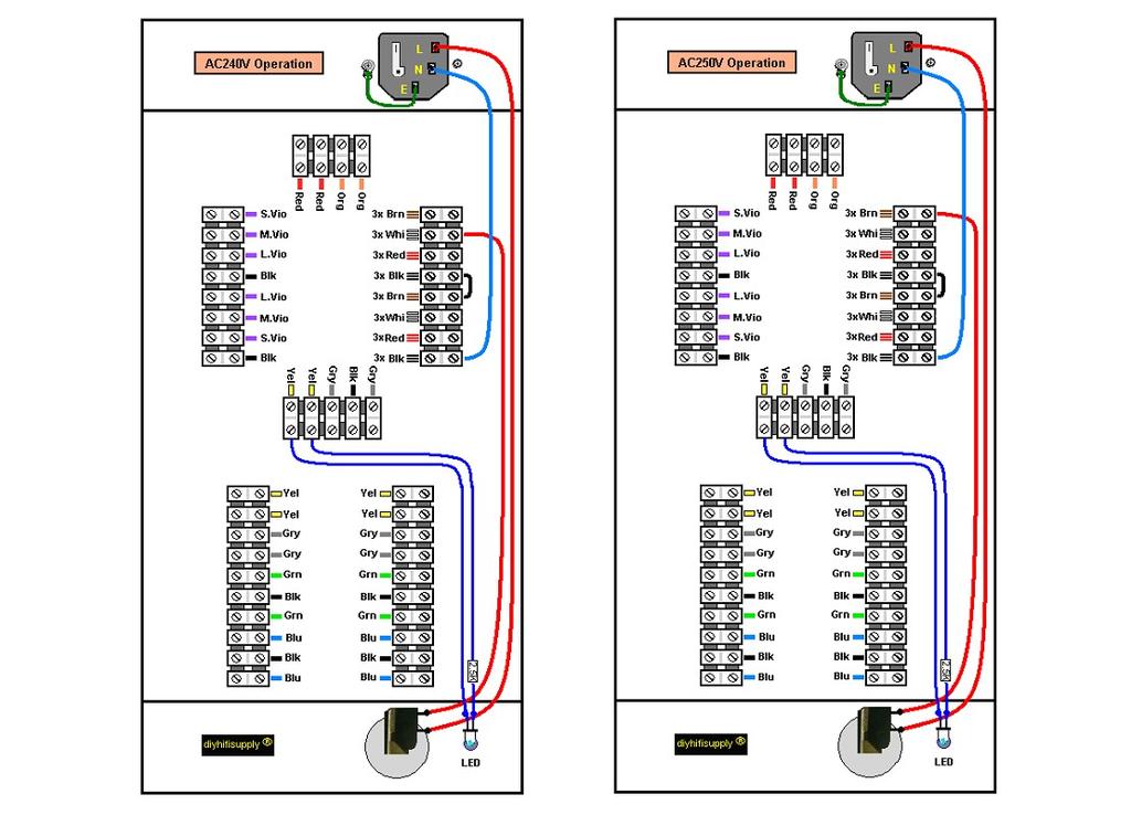
12

13 Chapter 5: Filament Transformer and Ground Connections Important: Twist the filament connection wires at least 3 turns to the inch to prevent hum and noise. lace in position as shown. Fit the Resistor and Capacitor for the RF suppression circuit to the 8 Ohm Speaker Terminal and the common speaker terminal as shown.

14 Chapter 6: Output Connections
15 Chapter 7: ower (FCUS) and Bias Supply (ABS) Connections Wire FCUS and ABS Modules as shown below..

16
17 Chapter 7b : FCUS and ABS bias supply testing, heater voltage testing Always observe polarity of test equipment to avoid damage. When first powering up the Ergo-Ella, disconnect the wires from the FCUS to the ABS. Then power up the Ergo-Ella. Eventually all 3 LED on the FCUS will light up about 1 minute). Measure the DCV at the B+Out connector on the FCUS (one probe to Chassis ground and one probe to label <<B+Out). It should be about V DC. Measure the input AC voltage to the FCUS at the input side of the FCUS (one probe on each point labelled AC310V>>). It should be V AC. Measure the DCV at the Bias -V Out label. It should be about V Turn power off. Always unplug power when connecting/disconnecting wires. Turn power on. Measure the voltages between pins 2 & 7 on the output tube sockets. The voltage should be 6.6V AC +/- 0.5V (it will drop back to 6.3V once loaded with the valve's heater. If the voltage is significantly different you need to check the polarity of the heater windings from the filament transformer. If the voltage is much too low it usually means one winding is connected in inverted polarity, causing the heater voltage to be low. Simply invert one of the windings from the heater transformer to correct the problem. If the voltage is much too high it usually means a connection was made wrongly. Finally measure the heater voltage to input and driver valve sockets (e.g. at the 6SN7 socket pin 7 & 8

18 Connect the 47uF film cap with 2 x 10uf top side capacitors to FCUS as shown, connect the two 10uF capacitors in the chassis as shown. roceed to make connections for Shuguang style EL34 tubes as shown below. ABS comes preconfigured with bias set for EL34 tube operation.
19 Chapter 7C: ABS Supply Testing If was all OK when testing the FCUS (7B) then connect ONE ABS to FCUS. Check that it powers up normally. After 2 minutes there should be about 0V at the ABS connector labelled 'B' in the diagrams. Then disconnect that ABS module and proceed to test the other ABS module in the same way. Always unplug power when connecting/disconnecting wires.

20 Chapter 8: Signal ath arts Connections
21 Chapter 9 Operational notes Do not yet insert the tubes! 1. Adjust the volume to lowest setting 2. Turn the chassis bottom facing up. lug in the power and switch on the unit with the power switch. Watch for sparking, smoke or any condition that would indicate miswiring. If you have burned out a fuse, you can find the fuse that needs to be replaced inside the little drawer in the IEC that slides out from the backside. Replace with same value type as etched on endcap. If OK proceed to the next step. If not, check for mistakes. 3. Check power tubes, pin 5 (counting clockwise from the #1 pin indicated in the diagram) for -50VDC (-ve probe to ground buss, +ve probe to pin 5. (Since this is a negative voltage you may need to reverse the probes - check on a high range first). Takes about 2 minutes for bias voltage to stabilize. 4. Check the voltage between pins 2, 7 on each power tube for 6.3VAC 10%. AC range on your meter, one probe to pin 2, one probe to pin 7 5. Middle 4 tubes. 2 are 9 pin, 2 are 8 pin. Again counting clockwise from #1 pin. 8 pin tubes: As above for measuring ACV, check between tube pins 7 and 8 for 6.3VAC 10% 6. 9 pin tubes: Check pins 4/5 for 6.3vac 10%. One probe to pin 4, one to pin Check B+ on S CB for ~400v dc. Again to test DC V, -ve probe to ground buss, +ve (red) probe to test point. Turn off the power. 8. A: Turn over unit. Insert the 4 EL34 power tubes into positions shown by the picture.. 9..Double check all your connections and refer to the circuit diagrams at the back of the manual whilst doing so. Inspect all solder joints for completeness. Check carefully to make sure that small pieces of hardware or solder drops are not left inside the chassis. Reinstall chassis plate. 10. Turn unit over and insert the other tubes into their respective sockets (6922s and 6N8s). Do not connect input source and volume pot on preamp must be fully counter clockwise! To be safe you can attach a 10W 10 ohm resistor across each pair of speaker posts. 11. Turn on power. If all OK, turn off the power. 12. Connect speakers and sound source (i.e. CD player). You should never operate the unit with no speaker load attached or with shorted speaker outputs whenever signal source is applied. 13. Turn on the power and input signal. Adjust volume pot to desired listening level. 1. Heater wire limits: V Distorted, low or poor quality sound 1. bias is incorrect Blown fuse 1. Metal debris has fallen inside chassis and is causing a short. 2. Output tube damaged. 3. Filter cap damaged. 4. S transformer has shorted internally or has been miswired for local voltage. Output tubes glow bright red
22 1. S voltage too high 2. bias incorrect 3. Output shorted or open when signal applied. 4. Old EL34s ower Tube sets: 1. EL34 2. KT88 and KT100 Adjust bias for above tubes as per: See Appendix Chapter 10 - Final Words The Ergo-Ella requires about 50 hours running in especially if you are using new tubes. Using more exotic NOS tubes can also improve and change the sound character of the amplifier. USE IN A WELL VENTILATED LACE TO ROVIDE AIR CIRCULATION. Copyright This manual is copyright of DIY HiFi Supply It must not be reproduced or distributed in paper or electronic form. Manual produced by: DIY HiFi Supply Ltd rev1.32

23 This is a finished Ergo-Ella with level 3 options and ABS module.

24
25 Appendix The ABS come preset for EL34. To change, replace 10 Ohm Cathode resistors for Output Tubes as follows: EL34: leave as is KT88/6550 fit 8.2 Ohm (47mA) KT100 fit 7.5 Ohm 52ma Note: the higher the anode current, the more heat and stress. Always monitor heat and provide enough airflow around amp. lease note that suggested anode currents give the best sound. Higher settings are not needed due to the state-of-the-art power supply and bias control. You do not have to change the cathode resistors just to operate the KT88/6550/KT100 and similar, you only need to adjust the resistors if you want to take advantage of the increased power form these Valves. If you keep the standard 10 Ohm Resistors the current will be set to 39mA regardless of the type of valve used and the high tension supply will be around 400V. lease check if this is compatible with the maximum ratings of the output tubes you wish to use. In principle many valves with a basing and connection identical to the EL34 but different electrical parameters and sound can be fitted. While not tested the KT66 & KT77 should work as well, as should some recent so-called EL156 which have actually the same socket pinout as the EL34 and hence do not fit historical EL156 Amplifiers. Tweaks and things to try Advanced kit builders may wish to experiment with connecting Ergo-Ella s output section to run in triode mode for lower output impedance and triode sound or in entode Mode for more power and the classic entode Sound. Schematic diagrams for these configuration are included below but not supported. In Triode mode around 30W Output ower are available, while in pentode mode more than 60W are available when using the EL34.
26 Ergo Ella Standard Schematic
27 Ergo Ella Triode Mode Schematic
28 Ergo Ella entode Mode Schematic
Lux Stereo Amplifier. Le Club Hifi : V1.7. DIY HiFi Supplywww.diyhifisupply.com
 Le Club Hifi : V1.7 Lux Stereo Amplifier DIY HiFi Supplywww.diyhifisupply.com Table of Contents Chapter 1-Introduction... Chapter Specification and Parts...5 Chapter 3 - Installation Notes...7 Chapter
LD91+ MonoMax with P:USH Power
 P. 1 diyhifisupply LD91+ MonoMax with P:USH Power For DIY and assembled units DIYHFS 5/16/2012 Contents 1.0 Introduction and Overview:...2 2.0 Parts list...5 3.0 AC Wiring...6 4.0 Output Transformers Choose
Ear+ Purist HD. Ear+ HD High Definition Stereo Headphone Amplifier
 Ear Purist HD Ear HD High Definition Stereo Headphone Amplifier 2AX7 Users' Manual ev Oct. 7/3 Mapletree Audio Design loyd Peppard.., Seeley's Bay, Ontario, Canada, K0H 2N0 (63) 387-3830 www.mapletreeaudio.com
ZOTL40 Mk.II POWER AMPLIFIER USER GUIDE. Linear Tube Audio Takoma Park, MD, USA
 ZOTL40 Mk.II POWER AMPLIFIER USER GUIDE Linear Tube Audio Takoma Park, MD, USA WARNING: For safety, the cover of this amplifier should be secured at all times. DC voltages as high as 1000V and peak AC
Stealth 60i Integrated Stereo/Mono Power Amplifier
 Stealth 60i Integrated Stereo/Mono Power Amplifier Users' Manual (Beta) Rev. Apr. 11/16 Mapletree Audio Design Lloyd Peppard R. R. 1, Seeley's Bay, Ontario, Canada, K0H 2N0 (613) 387-3830 info@mapletreeaudio.com
QUICKSILVER MX-190 OPERATING INSTRUCTIONS ,,-
 QUICKSILVER MX-190 OPERATING INSTRUCTIONS -------..,,- INPUT CONNECTIONS To maintain a short and concise signal path, the input connectors are mounted directly on the plug-in front-end circuit boards.
Lux91 MonoMax with P:USH Power
 Lux91 MonoMax with P:USH Power For DIY and assembled units DIYHFS 3/1/2010 Contents Introduction and Brief Overview:... 2 Specifications:... 4 Start Up... 4 Detailed Overview and Features:... 5 Circuit:...
FOUNTEK ALTITUDE Integrated Amplifier OWNERS MANUAL. A3500 ( Version -V1) 240V AC
 240V AC") FOUNTEK ALTITUDE 3500 Integrated Amplifier OWNERS MANUAL A3500 ( Version -V1) 240V AC 24-10-05 CONTENTS 3. INTRODUCTION 4. IMPORTANT NOTES ( WARNING!) 5. POWER INPUT CONNECTION 6. CONNECTING SPEAKERS 7.
FOUNTEK ALTITUDE 3500 Integrated Amplifier OWNERS MANUAL A3500 ( Version -V1) 240V AC 24-10-05 CONTENTS 3. INTRODUCTION 4. IMPORTANT NOTES ( WARNING!) 5. POWER INPUT CONNECTION 6. CONNECTING SPEAKERS 7.
Thank you very much for choosing Shuguang Audio Classic Series vacuum tube amplifier
 Thank you very much for choosing Shuguang Audio Classic Series vacuum tube amplifier (845 version). When opening the package, please carefully unpack all tubes and install each tube to its marked location
Mini Block Ultra Linear Class A Push-Pull Valve Power Amplifier
 Mini Block Ultra Linear Class A Push-Pull Valve Power Amplifier Precaution: This project uses potentially lethal voltages and should not be undertaken by anyone who is not familiar with working with such
MZ2 HEADPHONE AMPLIFIER, PREAMP, & STEREO AMPLIFIER USER GUIDE
 MZ2 HEADPHONE AMPLIFIER, PREAMP, & STEREO AMPLIFIER USER GUIDE Linear Tube Audio Takoma Park, MD, USA WARNING: For safety, the cover of this amplifier should be secured at all times. DC voltages as high
Ear+ Purist HD. Ear+ HD II High Definition Stereo Headphone Amplifier
 Ear+ Purist HD Ear+ HD II High Definition Stereo Headphone Amplifier Users' Manual Rev Mar 8/19 Mapletree Audio Design R. R. 1, Seeley's Bay, Ontario, Canada, K0H 2N0 (613) 387-3830 www.mapletreeaudio.com
The Wave (K-MOD103) GUITAR DWELL REVERB REVERB SWITCH ON OUT OFF
 GUITAR DWELL REVERB REVERB SWITCH ON OUT OFF") The Wave (K-MOD103) OUT IN GUITAR IN DWELL REVERB REVERB SWITCH ON GUITAR OUT POWER ON OFF OFF Please note, there are no labels for this kit. The controls, switches and connectors have only been labeled
The Wave (K-MOD103) OUT IN GUITAR IN DWELL REVERB REVERB SWITCH ON GUITAR OUT POWER ON OFF OFF Please note, there are no labels for this kit. The controls, switches and connectors have only been labeled
Manual Version July 2007
 Manual Version 1.2 - July 2007 Page 1 Table of Contents Section1: M3 Phono Board Build...3 Phono Board Parts List...3 Preparation...4 Fitting the Valve Bases...6 Installing the Resistors...7 Starting the
THE ZEN TRIODE EXPIREMENTERS AMPLIFIER KIT MODEL SE84CDIYMONO
 THE ZEN TRIODE EXPIREMENTERS AMPLIFIER KIT MODEL SE84CDIYMONO ASSEMBLY INSTRUCTIONS 2008 The circuit board has been designed to be used in 2 ways; A) Mounted on stand-offs to a piece of wood and B) Mounted
Super Stealth Monobloc Power Amplifier
 Super Stealth Monobloc Power Amplifier Special Edition Users' Manual Rev. Oct. /1 Mapletree Audio Design Lloyd Peppard R. R. 1, Seeley's Bay, Ontario, Canada, K0H N0 (61) -0 info@mapletreeaudio.com http://www.mapletreeaudio.com
Ultra 4B SE Special Edition. Stereo Phono/Line Preamplifier
 Modular Series Ultra B SE Special Edition Stereo Phono/Line Preamplifier User s Manual Phono Line Line Balance Volume Mapletree Audio Design Ultra B SE Stereo Preamplifier Rev. Feb. / Mapletree Audio Design
DIY Tube Stereo 70 Board - TubeZone Assembled -Instructions - Page 1
 DIY Tube Stereo 70 Board - TubeZone Assembled -Instructions - Page 1 Board and portions of manual, (c) 2006 Shannon Parks & DIYtube.com. Version specific instructions (c) 2006 Ned Carlson and Tubezone.net
audionet AMP 1 V2 User s Manual Stereo - Amplifier
 audionet AMP 1 V2 Stereo - Amplifier User s Manual 1 2 Contents 1 Preface... 4 1.1 Included... 5 1.2 Transport... 5 2 Overview control elements... 6 2.1 Front panel... 6 3 Overview connections... 7 3.1
1. Summary. 15/08/2009 Philips Valve Amplifier Type LBH1015/01 Page 1 of 7. Valve PA Amplifier. Philips label Model Code LBH1015/01 Serial No 1080
 15/08/2009 Philips Valve Amplifier Type LBH1015/01 Page 1 of 7 1. Summary Valve PA Amplifier. Philips label Model Code LBH1015/01 Serial No 1080 Two input, mono 60W amplifier with tone control and 50V/70V/100V
D. Gillespie Designs. SCA-35 Capacitor Board. Installation Manual. D. Gillespie Designs with EFB TM
 D. Gillespie Designs SCA-5 Capacitor Board with EFB TM Installation Manual D. Gillespie Designs www.tronola.com Thank you for choosing our SCA-5 Capacitor Board with *EFB. We feel it is the single most
22A3 Monaural Amplifier Owner s Manual
 22A3 Monaural Amplifier Owner s Manual www.bandwidthaudio.com sales@bandwidthaudio.com WARNING Never power on the amplifier without connecting a proper load Failure to do so will result in permanent damage
Simple EL84 Basic layout. DIY Paradise 13 June 2003
 Simple EL84 Basic layout DIY Paradise 13 June 2003 EL84 doesn t sing without feedback. EL84 has no bass. These are comments I gleamed off the World Wide Web from various places. The truth is, if the circuit
DD1-1300S. 500 Watts RMS Watts RMS Watts RMS- 1. Mono-Bloc Digital Power Amplifier
 DD1-1300S Mono-Bloc Digital Power Amplifier 500 Watts RMS- 4 900 Watts RMS- 2 Ultimate Sound, Inc. 1300 Watts RMS- 1 Ultimate Europe AB Ultimate Sound, Inc Ultimate Europe AB 163 University Parkway Flojelbergsgatan
Specimen Products Single Ended Stereo Amp Instruction Book
 Specimen Products Single Ended Stereo Amp Instruction Book Specimen tube amplifier designs are informed by decades of servicing and building musical instrument amps. As a result of being subjected to the
Jason Stull. Physics 498 (Physics of Music) Valve Junior Modification 5/13/2010
 Valve Junior Modification 5/13/2010") Jason Stull Physics 498 (Physics of Music) Valve Junior Modification 5/13/2010 1 Introduction My original idea for a class project was to build a tube guitar amplifier. I have wanted a tube amp for some
Jason Stull Physics 498 (Physics of Music) Valve Junior Modification 5/13/2010 1 Introduction My original idea for a class project was to build a tube guitar amplifier. I have wanted a tube amp for some
Kaskode One Phono Preamplifier Owner s Manual
 Kaskode One Phono Preamplifier Owner s Manual www.bandwidthaudio.com sales@bandwidthaudio.com WARNING Configuration of the Kaskode One will require removing the cover of the unit. Before removing the cover
Q-Tech. Q-Tech Commercial Series QTA 1360P/1480P Power Amplifiers. User Manual
 Q-Tech Power Amplifiers WARNING THIS APPLIANCE MUST BE EARTHED General Installation DO NOT run unbalanced high impedance microphone cables near mains, data, telephone or 70/100V line cables. DO NOT run
Octal Duo Stereo Headphone Amplifier
 Octal Duo Stereo Headphone Amplifier Users' Manual Rev Oct. 12/14 Mapletree Audio Design Al Freundorfer R. R. 1, Seeley's Bay, Ontario, Canada, K0H 2N0 (613) 387 3830 www.mapletreeaudio.com info@mapletreeaudio.com
American Power Design, Inc.
 FEATURES 4 Customer Selects Output Voltage 4 Outputs to 28 Vdc 4 Wide Input Ranges (10-20Vdc, 18-36Vdc, 20-60Vdc, 36-72Vdc) 4 Excellent Line & Load Regulation 4 Low Output Ripple 4 500 Vdc Output Isolation
BRIDGE MODE FOR THE STEREO 120. Preface to Everything PLEASE READ THIS FIRST! YOU MAY SAVE YOURSELF A LOT OF TROUBLE!
 BRIDGE MODE FOR THE STEREO 120 Preface to Everything PLEASE READ THIS FIRST! YOU MAY SAVE YOURSELF A LOT OF TROUBLE! At some point I made 4 Ohm 1 khz output power tests of single channels of the updated
American Power Design, Inc.
 FEATURES 4 Customer Selects Output Voltage 4 Outputs to 28 Vdc 4 Wide Input Ranges (10-20Vdc, 18-36Vdc, 20-60Vdc, 36-72Vdc) 4 Excellent Line & Load Regulation 4 500 Vdc Output Isolation 4 Continuous Short
Sterling. Power Amplifiers User Manual. Models Covered
 Sterling Power Amplifiers User Manual Models Covered Stereo 12 Watt Mk 1 & 2 Stereo Plus 18 Watt Mk 1 & 2 Stereo Integrated 12 & 18 Watt Mk 1 & 2 Stereo Integrated Remote 12 & 18 Watt Mk 1 & 2 Parallel
Copyright 1999 Wheatfield Audio LLC. All rights reserved. Printed in USA 11/99
 HA-2 Headphone Amplifier User s Manual Contents Safety... 3 Unpacking, Setup, and Connection... 4 Unpacking the amplifier... 4 Installing the tubes... 4 Connecting the amplifier... 4 Listening with the
XES-M50 Operating Instructions
 3-859-268-11(1) XES-M50 Operating Instructions 1997 by Sony Corporation Stereo Power Amplifier Operating Instructions Before operating the unit, please read this manual thoroughly and retain it for future
GOLDMUND MIMESIS SRM2.3 MONO AMPLIFIER
 GOLDMUND MIMESIS SRM2.3 MONO AMPLIFIER 1 GOLDMUND MIMESIS SRM2.3 MONO AMPLIFIER USER MANUAL ATTENTION : No connection or manipulation must be done before reading those instructions. Damage to the amplifier
WOO AUDIO WA2. Stereo Headphone & Pre Amplifier. Single-Ended, Class-A, Output Transformer-Less (OTL) Owner s Manual
 Owner s Manual") WOO AUDIO WA2 Stereo Headphone & Pre Amplifier Single-Ended, Class-A, Output Transformer-Less (OTL) Owner s Manual Please review this manual before operating your WOO AUDIO product. Inc. All rights reserved.
WOO AUDIO WA2 Stereo Headphone & Pre Amplifier Single-Ended, Class-A, Output Transformer-Less (OTL) Owner s Manual Please review this manual before operating your WOO AUDIO product. Inc. All rights reserved.
Mapletree Audio Design SR70A Special Red Driver Module for Dynaco ST-70
 Mapletree Audio Design S70A Special ed Driver Module for Dynaco ST-70 Installation instructions ev. Jan. 9/ The Special ed S70A driver module is a drop in replacement for the original driver board of the
Super Stealth + Monobloc Power Amplifier
 Super Stealth Monobloc Power Amplifier Users' Manual Rev. Nov. 9/ Mapletree Audio Design Lloyd Peppard R. R., Seeley's Bay, Ontario, Canada, K0H N0 (6) 7-0 info@mapletreeaudio.com http://www.mapletreeaudio.com
When you check the list of features offered by the PLMRA220,PLMRA420 you ll know you made the right choice with a Pyle Marine amplifier.
 congratulations... on your purchase of a Pyle Marine Series amplifier. This amplifier extends the Pyle tradition into a totally new series of amps, designed from the ground up to deliver the power, performance
REPAIRING THE RM KL400 LINEAR AMPLIFIER.
 REPAIRING THE RM KL400 LINEAR AMPLIFIER. Les Carpenter G4CNH December 2012 Page 1 of 20 The following is a step by step guide to fixing your KL400 amplifier. Each part will be individually tested up to
MANLEY LABORATORIES, INC. OWNER'S MANUAL MANLEY 50 WATT MONOBLOCK AMPLIFIER
 MANLEY LABORATORIES, INC. OWNER'S MANUAL MANLEY 50 WATT MONOBLOCK AMPLIFIER Manley Laboratories, Inc. 13880 Magnolia Ave. Chino, CA. 91710 tel: (909) 627-4256 fax: (909) 628-2482 CONTENTS SECTION PAGE
Summit Audio Model DCL-200 Dual Compressor-Limiter Operating Manual
 Summit Audio Model DCL-200 Dual Compressor-Limiter Operating Manual IMPORTANT!: CAREFULLY READ THE ENTIRE INSTRUCTION MANUAL BEFORE HOOKUP OR OPERATION OF THE DCL-200. WARNING!: HIGH VOLTAGE. THIS UNIT
Read This Page First
 Read This Page First If you are reading this you know the manuals are always available at QRPKITS.com. This is version 8.0 of the manual dated 4/27/2016. There is no need to print out the whole assembly
STEREO POWER AMPLIFIER OWNER MANUAL PR-150 DESIGNED IN U.K. PDF created with FinePrint pdffactory trial version
 STEREO POWER AMPLIFIER OWNER MANUAL PR-150 DESIGNED IN U.K. INTRODUCTION Congratulations on your purchase of MA PR-150 Stereo Power Amplifier. The performance of PR-150 is perfect for any audio application,
FUNCTION GENERATOR KIT
 FUNCTION GENERATOR KIT MODEL FG-500K Assembly and Instruction Manual Elenco Electronics, Inc. Copyright 2005 by Elenco Electronics, Inc. All rights reserved. Revised 2005 REV-B 753069 No part of this book
Josephson Engineering, Inc. 329A Ingalls Street Santa Cruz, California Josephson Engineering Rev B
 C725 Users Guide Josephson Engineering, Inc. 329A Ingalls Street Santa Cruz, California +1 831 420 0888 www.josephson.com 2017 Josephson Engineering Rev B C725 Users Guide Josephson C725 microphones are
Dynaco MK3 Electrolytic Cap Upgrade Assembly, Installation, and Adjustment Manual
 Page 1 PC-M3U Rev 1 I. Introduction Thanks for your purchase of our Mark 3 Quad Electrolytic Capacitor Replacement Board PC-M3U. It has been designed to replace the original Dynaco Quad (4 section) Aluminum
VOLUME AND TONE CONTROL - PREAMPLIFIER K8084
 VOLUME AND TONE CONTROL - PREAMPLIFIER K8084 When using one of our amplifiers (big or small), you always need a volume control and preferably also a tone control H8084IP-1 Features & specifications When
USER MANUAL VIVALDI MZ550A. Distribution Mixer Amplifier
 USER MANUAL VIVALDI MZ550A Distribution Mixer Amplifier 1. Security Precautions Carefully READ the instruction in this manual before use. Be sure to OBSERVE the INSTRUCTION in this manual regard convention
PROFESSIONAL POWER AMP
 Operating Instruction Manual PROFESSIONAL POWER AMP Model P-75D, P-150D, P-300D P-75D P-150D P-300D TOA Corporation KOBE, JAPAN Contents Precautions... 1 General Description... 2 Features... 2~ 3 Specifications...
5W Mono Amplifier Kit
 5W Mono Amplifier Kit Kit Construction Before you start assembling your kit there are a couple of important things you must do. FIRST read through these instructions entirely before you start construction
Monolith. Subwoofer System OWNERS MANUAL
 Monolith Subwoofer System OWNERS MANUAL CONTENTS Page No. 1) Safety instructions. 2) 3) 4) Connecting up your Monolith. Connecting up using the high level input. Connecting up using the low level input.
SPEAKER SELECTION/VOLUME CONTROL SYSTEM
 M O D E L SVL-2 SVL-2 SPEAKER SELECTION/VOLUME CONTROL SYSTEM NILES INSTALLATION & OPERATION GUIDE SVL-2 Speaker Selection/ Volume Control System TABLE OF CONTENTS Introduction 1 Features and Benefits
POWER AMPLIFIER. Owner s Manual Mode d emploi Bedienungsanleitung Manual de instrucciónes CLIP SIGNAL TEMP PROTECTION POWER
 POWER AMPLIFIER Owner s Manual Mode d emploi Bedienungsanleitung Manual de instrucciónes TEMP PROTECTION POWER A CLIP SIGNAL B ON OFF M Introduction Thank you for purchasing a Yamaha C450/320/160 series
THE RING RESONATOR (K-975)
") THE RING RESONATOR (K-975) OUTPUT BOOST The Ring Resonator An Octave Up Fuzz Modkitsdiy.com 9 VDC CENTER (-) ADAPTER TO AMP IN FROM GUITAR OUT Unplug when not in use to save battery life. Use these instructions
THE RING RESONATOR (K-975) OUTPUT BOOST The Ring Resonator An Octave Up Fuzz Modkitsdiy.com 9 VDC CENTER (-) ADAPTER TO AMP IN FROM GUITAR OUT Unplug when not in use to save battery life. Use these instructions
A 75-Watt Transmitter for 3 Bands Simplified Shielding and Filtering for TVI BY DONALD H. MIX, W1TS ARRL Handbook 1953 and QST, October 1951
 A 75-Watt Transmitter for 3 Bands Simplified Shielding and Filtering for TVI BY DONALD H. MIX, W1TS ARRL Handbook 1953 and QST, October 1951 The transmitter shown in the photographs is a 3-stage 75-watt
Summit Audio Model EQP-200B Dual Program Equalizer Operating Manual
 Summit Audio Model EQP-200B Dual Program Equalizer Operating Manual IMPORTANT!: CAREFULLY READ THE ENTIRE INSTRUCTION MANUAL BEFORE HOOKUP OR OPERATION OF THE EQP-200B. WARNING!: HIGH VOLTAGE. THIS UNIT
DIODE / TRANSISTOR TESTER KIT
 DIODE / TRANSISTOR TESTER KIT MODEL DT-100K Assembly and Instruction Manual Elenco Electronics, Inc. Copyright 1988 Elenco Electronics, Inc. Revised 2002 REV-K 753110 DT-100 PARTS LIST If you are a student,
TOA PROFESSIONAL POWER AMP
 Operating Instruction Manual TOA PROFESSIONAL POWER AMP Model P-150M, P-300M TOA ELECTRIC CO, LTD. KOBE, JAPAN Contents Precautions... 2 General Description... 2 Features... 3 Specifications... 4~5 Performance
user s manual PLA2170 PLA2270 PLA2370 PLA2470 PLA2570 PLA4170 PLA4270 PLA4370 limited warranty policy Brooklyn, NY 11204
 limited warranty policy a m p l i f i e r s All Pyle products are carefully constructed and thoroughly tested before shipment. Products purchased in the USA are warranted to be free of defects in material
SLP-2002 Stereo Balanced Vacuum Tube Preamplifier
 SLP-2002 Stereo Balanced Vacuum Tube Preamplifier Fully Balanced Vacuum Tube Line Stage Circuit Design with Cinema Bypass and Remote Volume Control CARY AUDIO DESIGN 1020 GOODWORTH DRIVE APEX, NORTH CAROLINA
i3speakers LX503 MK2 User Manual
 i3speakers LX503 MK2 User Manual Index Introduction 5 Precautions 6 Safety requirements 6 Caution servicing 7 EC Declaration of Conformity 7 Waste of Electrical and Electronic Equipment (WEEE) 7 Chapter
USER MANUAL. GOLDMUND TELOS 2500 NextGen Universal Power Amplifier
 USER MANUAL GOLDMUND TELOS 2500 NextGen Universal Power Amplifier Thank you for purchasing the GOLDMUND TELOS 2500 NextGen. You have acquired the best Universal Power Amplifier ever made for professional
Model Operating Manual
 Model 7500 DC to 1MHz Wideband Power Amplifier Operating Manual Copyright 2004. All rights reserved. Contents of this publication may not be reproduced in any form without the written permission of Krohn-Hite
MODEL 3 MONO AMPLIFIER OWNER S MANUAL
 MODEL 3 MONO AMPLIFIER OWNER S MANUAL TABLE OF CONTENTS Introduction Features Unpacking Instructions Installation * Space requirements * A.C. connections Input Impedance Selection Adjustable Gain Signal
Owner s Manual. VTSP-1A/166 Vacuum Tube Stereo Preamplifier
 VTSP-1A/166 Vacuum Tube Stereo Preamplifier Welcome! Table of Contents 3 Introduction 4 Features 6 Design Considerations 7 Front Panel Features 10 Rear Panel Features 12 Installation and Operation 13 Other
DIODE / TRANSISTOR TESTER KIT
 DIODE / TRANSISTOR TESTER KIT MODEL DT-100K 99 Washington Street Melrose, MA 02176 Phone 781-665-1400 Toll Free 1-800-517-8431 Visit us at www.testequipmentdepot.com Assembly and Instruction Manual Elenco
Project 747 VERSION 1.3 USER MANUAL February 22nd 2018
 VERSION 1.3 USER MANUAL February 22nd 2018 WWW.GARAGE1217.COM WARNING: Project requires knowledge of AC electrical systems, repair of said systems and restoration of said systems. If proper safety measures
THD FLEXI-50 INSTRUCTION MANUAL 1
 THD Flexi-50 Instruction Manual Thank you for your purchase of the THD Flexi-50 amplifier! The Flexi-50 is a precision hand-built 50-watt Class-AB amplifier with foot-switchable overdrive/boost, footswitchable
USER MANUAL GOLDMUND MIMESIS 29M Millennium Edition Power Amplifier
 USER MANUAL GOLDMUND MIMESIS 29M Millennium Edition Power Amplifier CONGRATULATIONS Thank you for purchasing the Goldmund Mimesis 29M Millennium Edition. You have acquired the best Analogue Power Amplifier
Instruction Kit MIXER AMPLIFIER GT 60C GT 125C. GROMMES-PRECISION SINCE-46
 Instruction Kit GT 60C GT 125C MIXER AMPLIFIER GROMMES-PRECISION 1-800-SINCE-46 www.grommesprecision.com Thank you for purchasing from Grommes~Precision! Grommes~Precision and its commercial audio division,
DPA-1200 ORDERCODE D4180 DPA-2400 ORDERCODE D4181 DPA-3400 ORDERCODE D4182
 Digital DPA-1200 DPA-2400 DPA-3400 ORDERCODE D4180 ORDERCODE D4181 ORDERCODE D4182 Congratulations! You have bought a great, innovative product from DAP Audio. The Dap Audio Vintage Digital Power Series
USER MANUAL QSM-606AZ QSM-612AZ QSM-624AZ MIXER AMPLIFIER
 USER MANUAL QSM-606AZ QSM-612AZ QSM-624AZ MIXER AMPLIFIER WARNING: THIS APPLIANCE MUST BE EARTHED IMPORTANT The wires in the mains lead are coloured In accordance with the following code: Green and Yellow:
USER MANUAL. GOLDMUND TELOS 1000 Universal Power Amplifier
 USER MANUAL GOLDMUND TELOS 1000 Universal Power Amplifier Thank you for purchasing the GOLDMUND TELOS 1000. You have acquired the best Universal Power Amplifier ever made for professional and domestic
Find a place where you can work through completion, without disturbing your
 Scan by Manual Manor ARIES SYSTEM 300 MUSIC SYNTHESIZER Page I of 4 MODULE AR-334 SEQUENCER ASSEMBLY INSTRUCTIONS It is recommended that you do the following before you proceed: Find a place where you
User Manual (English)
") Psvane TC5 Integrated KT120 Tube Amplifier User Manual (English) 1 P a g e Exclusively available at www.grantfidelity.com All copy rights reserved by Psvane Audio & Grant Fidelity page I Warnings: 1. Before
Psvane TC5 Integrated KT120 Tube Amplifier User Manual (English) 1 P a g e Exclusively available at www.grantfidelity.com All copy rights reserved by Psvane Audio & Grant Fidelity page I Warnings: 1. Before
American Audio. User Instructions. American Audio 4295 Charter Strret Los Angeles Ca Revised 5/01
 American Audio User Instructions American Audio 4295 Charter Strret Los Angeles Ca. 90058 Revised 5/01 CAUTION Do not open - risk of electric shock CAUTION: TO REDUCE THE RISK OF ELECTRIC SHOCK, DO NOT
BTM Series Pulsed RF Power Amplifier Modules. Application Note
 BTM Series Pulsed RF Power Amplifier Modules Application Note Tomco BT Series Pulsed RF Amplifier Modules - Application note Contents Contents...2 Amplifier Safety Precautions...3 Hazardous Materials Warning:...4
damage. expiration date. also include a check or money order for $18.00 for return shipping, and R.A. number
 limited warranty policy a m p l i f i e r s All Pyle products are carefully constructed and thoroughly tested before shipment. Products purchased in the USA are warranted to be free of defects in material
You Just Brought an Old Radio Home: Now What Do You Do?
 You Just Brought an Old Radio Home: Now What Do You Do? Raymond Cady goldenageradiorestoration.com Whether you are just beginning to collect antique radios or you have been at it for a number of years,
Build Your Own Clone Spring Reverb Kit Instructions
 Build Your Own Clone Spring Reverb Kit Instructions Warranty: BYOC, Inc. guarantees that your kit will be complete and that all parts and components will arrive as described, functioning and free of defect.
Archivist s Note: The plans are mislabeled and are actually for a tube-driven tremolo. See letter to the editor at the end of this document.
 Archivist s Note: The plans are mislabeled and are actually for a tube-driven tremolo. See letter to the editor at the end of this document. Build Your Own Vibrato Make like Elvis with an "electronic"
The 6LE8 One Tube Broadcaster
 The 6LE8 One Tube Broadcaster Introduction The purpose of this broadcaster is to transmit your favorite music to every AM radio in your home. The transmitting power is so low that it should not bother
SoftRock v5.0 Builder s Notes. December 12, Building a QSD Kit
 SoftRock v5.0 Builder s Notes December 12, 2005 Building a QSD Kit Be sure to use a grounded tip soldering iron in building the QSD board. The soldering iron needs to have a small tip, (0.05-0.1 inch diameter),
1160 Stereo Power Amplifier
 1160 Stereo Power Amplifier 03/01/2018 Rev. 1.0 P/N: 91055 Boulder Amplifiers, Inc. 255 S. Taylor Ave. Louisville, CO 80027 (303) 449-8220 www.boulderamp.com About About Boulder Amplifiers, Inc. Boulder
Modifying The Heath HA-14 For 6 Meters Greg Chartrand - W7MY 4/22/07
 Introduction The Heathkit HA-14 was one of the few electron tube linear amplifiers intended for mobile use but few were purchased with the 12 volt mobile power supply. Most hams bought the HA-14 for base
M-300 Mono power amplifier User s guide
 M-300 Mono power amplifier User s guide M-300 Mono power amplifier User s guide Specifications: Contents: Power output: 8Ω: 290W, 0.01% THD SPECIFICATIONS Page 2 Input impedance: Gain: 4Ω: 580W, 0.01%
Assembly Instructions for the FRB FET FM 70 Watt Amp
 Assembly Instructions for the FRB FET FM 70 Watt Amp 1.) Orient the circuit board with the diagram 2.) Use a narrow chisel tip 25-30 watt soldering iron for assembly 3.) All the small parts are taped onto
Assembly Instructions
 Assembly Instructions For the SSQ-2F 3.1 MHz Rife Controller Board Kit v1.41 Manual v1.00 2012 by Ralph Hartwell Spectrotek Services GENERAL ASSEMBLY INSTRUCTIONS Arrange for a clean work surface with
PM124 Installation Instructions. See important note about revisions of this board on the last page.
 Marchand Electronics Inc. PO Box 473, Webster, NY 14580 Tel:(716) 872-0980 Fax:(716) 872-1960 info@marchandelec.com http://www.marchandelec.com (c)1997 Marchand Electronics Inc. PM124 Installation Instructions
WA3RNC 30 METER CRYSTALPLEXER TRANSMITTER KIT ASSEMBLY INSTRUCTIONS
 WA3RNC 30 METER CRYSTALPLEXER TRANSMITTER KIT ASSEMBLY INSTRUCTIONS Description The WA3RNC 30 Meter Crystalplexer is a low power crystal controlled QRP transmitter offering a significantly improved tuning
Pacific Antenna Low Pass Filter Kit
 Pacific Antenna Low Pass Filter Kit Description Many basic transmitter and/or transceiver designs have minimal filtering on their output and frequently have significant harmonic content in their signals.
T L Audio. User Manual EQ1 VALVE EQUALISER. Tony Larking Professional Sales Limited, Letchworth, England.
 T L Audio User Manual EQ1 VALVE EQUALISER Tony Larking Professional Sales Limited, Letchworth, England. Tel: 01462 490600, International +44 1462 490600. Fax: 01462 490700, International +44 1462 490700.
NEW. HANDMADE in Germany.
 NEW HANDMADE in Germany. Integrated amplifier Ti 100 Mk II The Lyric Ti 100 Mk II is a pure single-ended class A amplifier. Its subtlety, naturalness, charm and dynamics converge for a fantastic listening
JCM W GUITAR AMPLIFIER. User s Manual
 JCM 800 2203 100W GUITAR AMPLIFIER User s Manual 1 Thank you for the purchase of your Ceriatone guitar amplifier! Here, we hope to explain how best to use your new amp. Table of Contents 1) About the 2203..
Quick Start Guide. Table of Contents
 Quick Start Guide Table of Contents Pre-Installation... 2 Safety Conventions... 3 General Descriptions... 4 Specifications... 5 Front Panel Functions... 8 Back Panel Functions... 9 Details of Plug-In Mode...
Mono Amplifier. LM386 Headphone Amp
 Mono Amplifier LM386 Headphone Amp Layout On/Off Switch - cuts power to the circuit Mono Input Jack: use either L or R or solder together Schematic Step 1 - Parts List 1.) R1-10ohm Resistor - Brown Black
plifier D-501 otion Am Tactile M
 Tactile Motion Amplifier D-501 IMPORTANT SAFETY INSTRUCTIONS WARNING: 1. Read and keep these instructions for future reference. 2. Do not use this apparatus near water. 3. Clean only with a dry cloth.
USER MANUAL MG-TA1000 POWER AMPLIFIER
 USER MANUAL MG-TA1000 POWER AMPLIFIER INDEX: INTRODUCTION SAFETY INSTRUCTIONS OPERATING PRECAUTIONS FEATURES OF PANAL CONTROLS FRONT & REAR PPANEL DISPLAY CONNECTING INPUTS SPEAKER CONNECTIONS INTRODUCTION: