6. Modulation and Multiplexing Techniques
|
|
|
- Eugenia Elliott
- 6 years ago
- Views:
Transcription
1 6. Modulation and Multiplexing Techniques The quality of analog transmission is S/N (signal to noise ratio). signal power S/N = baseband noise power S/N can be greater than C/N. For instance for FM (frequency modulation) TV transmission: [S/N] can be up to 35 db larger than [C/N]. The quality of digital transmission is BER (bit error rate). number of improperly detected bits during time t BER = total number of bits detected during time t e.g. BER = 10-5 è on average 1 bit in 100,000 is wrong. S/N and BER depend on C/N and on the modulation technique. Analogue modulation Amplitude modulation (AM) Frequency modulation (FM) Phase modulation (PM Digital modulation Amplitude shift keying (ASK) Frequency shift keying (FSK) Phase shift keying (PSK) o Binary PSK (BPSK) o Quadrature PSK (QPSK)
2 Analogue modulation carrier carrier modulator modulated carrier A 0 cos(w c t+y) C(t)=A(t)cos[w c t+f(t)] modulating signal or baseband signal m(t) (from data, TV ) AM: message is carried in A(t): C(t)= A(t)cos[w c t+f 0 ] FM: message is carried in w(t): C(t)=A 0 cos[w(t)+f 0 ] PM: message is carried in f(t) : C(t)=A 0 cos[w c t+f(t)] Demodulation Modulated carrier C(t) Carrier demodulator recovered baseband signal m(t) A 0 cos[w c t+y ] Amplitude modulation (AM) c(t) = A(t) cos (w c t + f 0 ) w c : carrier angular frequency = A 0 [1+D a m(t)] cos (w c t + f 0 )
3 D a : 0 D a 1 : amplitude modulation index m(t) : m(t) 1 : baseband signal Graphical example for a special case: m(t) = cos w m t A 0 w m : modulating frequency D a =0 A 0 cos[w c t+f 0 ] m(t) 1 m(t) = cos w m t -1 c(t) A 0 D a =0.5 C(t)=A 0 [1+ 0.5cosw m t]cos(w c t + f 0 ) -A 0 AM spectrum Amplitude baseband spectrum f=w/2p 0 f m f c - f m f c f c +f m
4 General case: baseband signal m(t) consists of sine waves with continuous range of frequencies. C(t) A 0 0 AM spectrum for general case Amplitude triangular baseband spectrum lower sideband upper sideband f max f c - f max f c f c +f max Here, the spectrum of m(t) is just plotted as a triangularly shaped spectrum. S/N» C/N at detector output 1. AM does not provide improvement of S/N over C/N. 2. AM is very susceptible to non-linear distortions as produced in satellite transponders, and is easily disturbed by link noise and interference. è AM is essentially never used in satellite communications. Frequency modulation (FM) c(t) = A 0 cos (w(t) + f 0 ) w c : carrier angular frequency
5 = A 0 cos[(w c t) +D ò m(t) dt + f 0 ] D: constant For special case : m(t) = cos w m t c(t) = A 0 cos[(w c t) + b sin w m t + f 0 ] b = ad/w m = Dw/w m = Df/f m : modulation index Graphical example: w m = 2p f m Dw = 2p Df : modulation frequency : max. frequency deviation, i.e. the frequency of the modulated carrier varies between w c =-Dw and w c =+Dw. b=0 c(t)=a 0 cos[w c t+y] m(t)=a cos w m t b>0 c(t)=a 0 [(w c t)+bsin w m t+f 0 ] How does the spectrum look? Complicated since the FM waveform takes the form of cos of sin! è Spectrum can be represented by Bessel functions.

6 n ³ 0 FM spectrum f m f c f c +f m There is an infinite number of side frequencies. However, the amplitudes of the side spectral components decrease very rapidly for those components larger than b. è We do not need an infinitely wide filter bandwidth. Most of the information of a FM signal is in fact passed through a filter with a finite bandwidth, B, that depends on the modulation index b. The bandwidth, B, is essentially the range in frequencies from f c (b + 1) f m to f c + (b + 1) f m. B=2 (b + 1) f m B=2 (Df + f m ) : Carson s rule If m(t) is not just a cosine wave but a signal with a continuous range of spectral components, then we characterize such a spectrum as before as follows:
7 Amplitude f max Then: b= DF/f max B= 2 (DF+ f max ) f max : modulation index for highest frequency in baseband spectrum. b is also sometimes called the deviation ratio, D. DF is similar to Df, that is, it is the frequency range over which the carrier frequency is modulated. Examples: 1) A 100 MHz carrier is frequency modulated by a 1 khz tone which produces frequency deviations of up to 75 khz. b = Df/f m = 75/1 = 75 B= 2 (Df+ f m ) = 2 (75 + 1) = 152 khz 2) A video signal of bandwidth 4.2 MHz is used to frequencymodulate a carrier with DF = MHz. D = b= DF/f max = 10.75/4.2 = 2.56
8 B= 2 (DF+ f max ) = 2 ( ) = 29.9 MHz Signal-to-noise ratio For FM, the S/N is not equal to C/N. There are three factors that cause an improvement of S/N over C/N. 1. The processing gain K R of the detector as a function of b. S/N = K R C/N K R = 3 (b + 1) b 2 (This is valid only if [C/N] ³ 10 db) Example: For a video signal with b =2.56 è K R = 70 or 18.5 db 2. Preemphasis and Deemphasis The noise at the output of an FM demodulator where conversion back to baseband takes place, increases with increasing frequency. Receiver Amplitude Baseband spectrum of modulating signal m(t) without preemphasis Noise spectrum S/N is lower for higher f f Transmitter modulating signal spectrum before and after preemphasis
9 Receiver before de-emphasis after de-emphasis è Increase of S/N by P: P = emphasis improvement factor [P] 4 db for telephony [P] 13 db for TV 3. Noise weighting By modifying the noise spectrum and adjusting it to the response of the output device and /or the response to the human ear, S/N can be further improved, by [W]. [W] 2.5 db for telephony [W] 12 db for TV Multiplexing Mixed upward to modulate carrier at 6 GHz 70 MHz LO FM modulators 70 MHz LO FM demodulators Frequency division multiplexer Frequency division demultiplexer Baseband channels, terrestrial link
10 The most common analogue multiplexing technique is frequency division multiplexing (FDM). The most common digital multiplexing technique is time division multiplexing (TDM). FDM and TDM are transmission features. FDM and TDM should not be confused with frequency division multiple access (FDMA) and time division multiple access (TDMA). FDMA and TDMA are traffic features. Hirarchical structure of FDM according to CCITT (CCITT Comité Consultatif Internationale de Télégraphique et Téléphonique (International Telegraph and Telephone Consultative Committee) is an agency of the International Telecommunications Union (ITU). The ITU is an agency of the UN. The CCITT is an agency coordinating telephone and data communications systems on a worldwide basis and dealing with regulatory matters and with technical standards.)
11 12 baseband (voice channels) (1) khz khz khz (2) 108 khz khz khz khz (12) khz khz khz 64 khz khz Multiplexed signal ( 1 group) khz
12 Spectra are separated by 4 khz to allow for guardband for filtering purposes so that distortions from neighbouring channels are limited. 5 groups (1) khz khz khz (2) 420 khz khz khz khz (5) khz khz khz 612 khz khz Multiplexed signal (1 supergroup) khz
13 5 supergroups 1 basic mastergroup 3 basic mastergroups 1 super mastergroup 900 voice channels multiplexed! ,380 khz 12 (voice) channels è 1 group 5 groups è 1 supergroup 5 supergroups è 1 basic mastergroup 3 mastergroups è 1 super mastergroup The super mastergroup is the highest baseband unit voice channels are frequency division multiplexed. However, lots of other schemes are in use.
14 Transmitting and receiving ends of a typical FDM system Incoming voice channels composite FDM signal 70 MHz FM signal bandwidth: B IF =2(DF+f max ) 0 -- f max to converters and Multi- Frequency Modulator b=df/f max or transmitters plexer 0 f max b=df rms /f max khz b (bandwidth)=3.1 khz f c =70 MHz DF rms : rms frequency deviation per channel DF : peak frequency deviation w.r.t. all channels : center frequency of individual channel f m from IF amplifier, composite FDM signal outgoing voice channels 70 MHz FM signal Frequency Demultiplexer Demodulator C/N (overall C/N of link) S/N S/N=C/N 3(b+1)b 2 PW F LO 70 MHz
15 Example for S/N of a typical FDM system: [C/N] = 25 db [P] = 4 db [W] = 2.5 db DF = 281 khz DF rms = 35 khz f max = 108 khz b = 3.1 khz [S/N] = [C/N] + [3 ( b + 1) b 2 ] + [P] + [W] = = db
16 The baseband signal Here are 4 different kinds Wikipedia
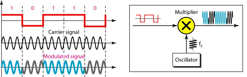
17 Digital modulation carrier carrier modulator modulated carrier m(t) ASK (amplitude shift keying) OOK (on-off keying) FSK (frequency shift keying) PSK (phase shift keying) BPSK (binary PSK) QPSK (quadrature PSK) Digital de-modulation Modulated carrier Carrier demodulator recovered baseband signal

18 ASK FSK (Binary) PSK

19 QPSK: four distinct phases are utilized. That Means that essentially two BPSK signals are transmitted at once è rate of transmission is doubled. Baseband bandwidth: The baseband bandwidth, B, of the digital modulating signal depends on the bit rate, R b, and the type of modulation and the filters involved For BPSK : B IF [Hz] = R b [bits per second] For FSK, the bandwidth is larger. Bit error rate (BER) BER characterizes quality of digital transmission. erfc is the complementary error function E b Energy per bit = db [E b /N 0 ] 10 db N 0 Noise power spectral density P R received power (W:J/s) E b = = R b bit rate (bits/s)
![If B N = R B Example: [C/N] = [E b / N 0 ] = 1.](/docs-images/74/70979305/images/20-0.jpg "56 db è BER = 5 10-2 = 6 db è BER = 2 10-3 improvement of BER is possible through coding.")

20 If B N = R B Example: [C/N] = [E b / N 0 ] = 1.56 db è BER = = 6 db è BER = improvement of BER is possible through coding. By encoding extra bits (redundant bits) it is possible to detect and correct certain errors in the decoding process. However, transmission rate is reduced è E b is reduced. But error rate is also reduced. For E b / N 0 ³ 5 db, coding gain can be achieved. Example: E b / N 0 = 6 db è BER 10-7 can be achieved!
Chapter 7 Multiple Division Techniques for Traffic Channels
 Introduction to Wireless & Mobile Systems Chapter 7 Multiple Division Techniques for Traffic Channels Outline Introduction Concepts and Models for Multiple Divisions Frequency Division Multiple Access
MODULATION AND MULTIPLE ACCESS TECHNIQUES
 1 MODULATION AND MULTIPLE ACCESS TECHNIQUES Networks and Communication Department Dr. Marwah Ahmed Outlines 2 Introduction Digital Transmission Digital Modulation Digital Transmission of Analog Signal
Outline. Communications Engineering 1
 Outline Introduction Signal, random variable, random process and spectra Analog modulation Analog to digital conversion Digital transmission through baseband channels Signal space representation Optimal
Chapter 7. Multiple Division Techniques
 Chapter 7 Multiple Division Techniques 1 Outline Frequency Division Multiple Access (FDMA) Division Multiple Access (TDMA) Code Division Multiple Access (CDMA) Comparison of FDMA, TDMA, and CDMA Walsh
Frequency Modulation
 Frequency Modulation transferred to the microwave carrier by means of FM. Instead of being done in one step, this modulation usually takes place at an intermediate frequency. signal is then frequency multiplied
B.Tech II Year II Semester (R13) Supplementary Examinations May/June 2017 ANALOG COMMUNICATION SYSTEMS (Electronics and Communication Engineering)
 Supplementary Examinations May/June 2017 ANALOG COMMUNICATION SYSTEMS (Electronics and Communication Engineering)") Code: 13A04404 R13 B.Tech II Year II Semester (R13) Supplementary Examinations May/June 2017 ANALOG COMMUNICATION SYSTEMS (Electronics and Communication Engineering) Time: 3 hours Max. Marks: 70 PART A
Code: 13A04404 R13 B.Tech II Year II Semester (R13) Supplementary Examinations May/June 2017 ANALOG COMMUNICATION SYSTEMS (Electronics and Communication Engineering) Time: 3 hours Max. Marks: 70 PART A
ECE5713 : Advanced Digital Communications
 ECE5713 : Advanced Digital Communications Bandpass Modulation MPSK MASK, OOK MFSK 04-May-15 Advanced Digital Communications, Spring-2015, Week-8 1 In-phase and Quadrature (I&Q) Representation Any bandpass
INTRODUCTION TO COMMUNICATION SYSTEMS AND TRANSMISSION MEDIA
 COMM.ENG INTRODUCTION TO COMMUNICATION SYSTEMS AND TRANSMISSION MEDIA 9/9/2017 LECTURES 1 Objectives To give a background on Communication system components and channels (media) A distinction between analogue
EE3723 : Digital Communications
 EE3723 : Digital Communications Week 8-9: Bandpass Modulation MPSK MASK, OOK MFSK 04-May-15 Muhammad Ali Jinnah University, Islamabad - Digital Communications - EE3723 1 In-phase and Quadrature (I&Q) Representation
Amplitude Modulation, II
 Amplitude Modulation, II Single sideband modulation (SSB) Vestigial sideband modulation (VSB) VSB spectrum Modulator and demodulator NTSC TV signsals Quadrature modulation Spectral efficiency Modulator
CHAPTER 2. Instructor: Mr. Abhijit Parmar Course: Mobile Computing and Wireless Communication ( )
") CHAPTER 2 Instructor: Mr. Abhijit Parmar Course: Mobile Computing and Wireless Communication (2170710) Syllabus Chapter-2.3 Modulation Techniques Reasons for Choosing Encoding Techniques Digital data,
CHAPTER 2 Instructor: Mr. Abhijit Parmar Course: Mobile Computing and Wireless Communication (2170710) Syllabus Chapter-2.3 Modulation Techniques Reasons for Choosing Encoding Techniques Digital data,
Code No: R Set No. 1
 Code No: R05220405 Set No. 1 II B.Tech II Semester Regular Examinations, Apr/May 2007 ANALOG COMMUNICATIONS ( Common to Electronics & Communication Engineering and Electronics & Telematics) Time: 3 hours
4.1 REPRESENTATION OF FM AND PM SIGNALS An angle-modulated signal generally can be written as
 1 In frequency-modulation (FM) systems, the frequency of the carrier f c is changed by the message signal; in phase modulation (PM) systems, the phase of the carrier is changed according to the variations
Wireless Communication Fading Modulation
 EC744 Wireless Communication Fall 2008 Mohamed Essam Khedr Department of Electronics and Communications Wireless Communication Fading Modulation Syllabus Tentatively Week 1 Week 2 Week 3 Week 4 Week 5
Digital Modulation Schemes
 Digital Modulation Schemes 1. In binary data transmission DPSK is preferred to PSK because (a) a coherent carrier is not required to be generated at the receiver (b) for a given energy per bit, the probability
Digital Modulation Lecture 01. Review of Analogue Modulation Introduction to Digital Modulation Techniques Richard Harris
 Digital Modulation Lecture 01 Review of Analogue Modulation Introduction to Digital Modulation Techniques Richard Harris Objectives You will be able to: Classify the various approaches to Analogue Modulation
Objectives. Presentation Outline. Digital Modulation Lecture 01
 Digital Modulation Lecture 01 Review of Analogue Modulation Introduction to Digital Modulation Techniques Richard Harris Objectives You will be able to: Classify the various approaches to Analogue Modulation
 Modulations Analog Modulations Amplitude modulation (AM) Linear modulation Frequency modulation (FM) Phase modulation (PM) cos Angle modulation FM PM Digital Modulations ASK FSK PSK MSK MFSK QAM PAM Etc.
DIGITAL COMMUNICATIONS SYSTEMS. MSc in Electronic Technologies and Communications
 DIGITAL COMMUNICATIONS SYSTEMS MSc in Electronic Technologies and Communications Bandpass binary signalling The common techniques of bandpass binary signalling are: - On-off keying (OOK), also known as
CSCD 433 Network Programming Fall Lecture 5 Physical Layer Continued
 CSCD 433 Network Programming Fall 2016 Lecture 5 Physical Layer Continued 1 Topics Definitions Analog Transmission of Digital Data Digital Transmission of Analog Data Multiplexing 2 Different Types of
Appendix A. Satellite Signal Processing Elements
 Appendix A Satellite Signal Processing Elements This appendix provides an overview of the basic signal processing elements that are present in virtually all traditional communications systems, including
Elements of Communication System Channel Fig: 1: Block Diagram of Communication System Terminology in Communication System
 Content:- Fundamentals of Communication Engineering : Elements of a Communication System, Need of modulation, electromagnetic spectrum and typical applications, Unit V (Communication terminologies in communication
Principles of Communications ECS 332
 Principles of Communications ECS 332 Asst. Prof. Dr. Prapun Suksompong prapun@siit.tu.ac.th 5. Angle Modulation Office Hours: BKD, 6th floor of Sirindhralai building Wednesday 4:3-5:3 Friday 4:3-5:3 Example
AM Limitations. Amplitude Modulation II. DSB-SC Modulation. AM Modifications
 Lecture 6: Amplitude Modulation II EE 3770: Communication Systems AM Limitations AM Limitations DSB-SC Modulation SSB Modulation VSB Modulation Lecture 6 Amplitude Modulation II Amplitude modulation is
CSCD 433 Network Programming Fall Lecture 5 Physical Layer Continued
 CSCD 433 Network Programming Fall 2016 Lecture 5 Physical Layer Continued 1 Topics Definitions Analog Transmission of Digital Data Digital Transmission of Analog Data Multiplexing 2 Different Types of
EXPERIMENT WISE VIVA QUESTIONS
 EXPERIMENT WISE VIVA QUESTIONS Pulse Code Modulation: 1. Draw the block diagram of basic digital communication system. How it is different from analog communication system. 2. What are the advantages of
Amplitude Modulation II
 Lecture 6: Amplitude Modulation II EE 3770: Communication Systems Lecture 6 Amplitude Modulation II AM Limitations DSB-SC Modulation SSB Modulation VSB Modulation Multiplexing Mojtaba Vaezi 6-1 Contents
Digital Communication System
 Digital Communication System Purpose: communicate information at required rate between geographically separated locations reliably (quality) Important point: rate, quality spectral bandwidth, power requirements
Modulation is the process of impressing a low-frequency information signal (baseband signal) onto a higher frequency carrier signal
 onto a higher frequency carrier signal") Modulation is the process of impressing a low-frequency information signal (baseband signal) onto a higher frequency carrier signal Modulation is a process of mixing a signal with a sinusoid to produce
Modulation is the process of impressing a low-frequency information signal (baseband signal) onto a higher frequency carrier signal Modulation is a process of mixing a signal with a sinusoid to produce
What is an FDM-TDM Transmultiplexer *
 OpenStax-CNX module: m31548 1 What is an FDM-TDM Transmultiplexer * John Treichler This work is produced by OpenStax-CNX and licensed under the Creative Commons Attribution License 3.0 1 Frequency-Division
Lecture 6. Angle Modulation and Demodulation
 Lecture 6 and Demodulation Agenda Introduction to and Demodulation Frequency and Phase Modulation Angle Demodulation FM Applications Introduction The other two parameters (frequency and phase) of the carrier
Data Encoding g(p (part 2)
") Data Encoding g(p (part 2) CSE 3213 Instructor: U.T. Nguyen 10/11/2007 12:44 PM 1 Analog Data, Digital Signals (5.3) 2 1 Analog Data, Digital Signals Digitization Conversion of analog data into digital
Data Encoding g(p (part 2) CSE 3213 Instructor: U.T. Nguyen 10/11/2007 12:44 PM 1 Analog Data, Digital Signals (5.3) 2 1 Analog Data, Digital Signals Digitization Conversion of analog data into digital
CS441 Mobile & Wireless Computing Communication Basics
 Department of Computer Science Southern Illinois University Carbondale CS441 Mobile & Wireless Computing Communication Basics Dr. Kemal Akkaya E-mail: kemal@cs.siu.edu Kemal Akkaya Mobile & Wireless Computing
Mobile Communication An overview Lesson 03 Introduction to Modulation Methods
 Mobile Communication An overview Lesson 03 Introduction to Modulation Methods Oxford University Press 2007. All rights reserved. 1 Modulation The process of varying one signal, called carrier, according
Angle Modulated Systems
 Angle Modulated Systems Angle of carrier signal is changed in accordance with instantaneous amplitude of modulating signal. Two types Frequency Modulation (FM) Phase Modulation (PM) Use Commercial radio
ISHIK UNIVERSITY Faculty of Science Department of Information Technology Fall Course Name: Wireless Networks
 ISHIK UNIVERSITY Faculty of Science Department of Information Technology 2017-2018 Fall Course Name: Wireless Networks Agenda Lecture 4 Multiple Access Techniques: FDMA, TDMA, SDMA and CDMA 1. Frequency
Signal Encoding Techniques
 2 Techniques ITS323: to Data Communications CSS331: Fundamentals of Data Communications Sirindhorn International Institute of Technology Thammasat University Prepared by Steven Gordon on 3 August 2015
 DEPARTMENT OF COMPUTER GCE@Bodi_ SCIENCE GCE@Bodi_ AND ENIGNEERING GCE@Bodi_ GCE@Bodi_ GCE@Bodi_ Analog and Digital Communication GCE@Bodi_ DEPARTMENT OF CsE Subject Name: Analog and Digital Communication
SUBCARRIERS IN MICROWAVE AND SATELLITE SYSTEMS
 SUBCARRIERS IN MICROWAVE AND SATELLITE SYSTEMS By: Frank McClatchie FM SYSTEMS, INC 1-800-235-6960 SUBCARRIERS DEFINED: In the early days they were called Diplexers, alluding to their main function at
Mobile & Wireless Networking. Lecture 2: Wireless Transmission (2/2)
") 192620010 Mobile & Wireless Networking Lecture 2: Wireless Transmission (2/2) [Schiller, Section 2.6 & 2.7] [Reader Part 1: OFDM: An architecture for the fourth generation] Geert Heijenk Outline of Lecture
192620010 Mobile & Wireless Networking Lecture 2: Wireless Transmission (2/2) [Schiller, Section 2.6 & 2.7] [Reader Part 1: OFDM: An architecture for the fourth generation] Geert Heijenk Outline of Lecture
Downloaded from 1
 VII SEMESTER FINAL EXAMINATION-2004 Attempt ALL questions. Q. [1] How does Digital communication System differ from Analog systems? Draw functional block diagram of DCS and explain the significance of
AM, PM and FM mo m dula l ti t o i n
 AM, PM and FM modulation What is amplitude modulation In order that a radio signal can carry audio or other information for broadcasting or for two way radio communication, it must be modulated or changed
TSEK02: Radio Electronics Lecture 2: Modulation (I) Ted Johansson, EKS, ISY
 Ted Johansson, EKS, ISY") TSEK02: Radio Electronics Lecture 2: Modulation (I) Ted Johansson, EKS, ISY 2 Basic Definitions Time and Frequency db conversion Power and dbm Filter Basics 3 Filter Filter is a component with frequency
TSEK02: Radio Electronics Lecture 2: Modulation (I) Ted Johansson, EKS, ISY 2 Basic Definitions Time and Frequency db conversion Power and dbm Filter Basics 3 Filter Filter is a component with frequency
Transmission of Analog Signal - II
 CS311: DATA COMMUNICATION Transmission of Analog Signal - II Dr. Manas Khatua Assistant Professor Dept. of CSE IIT Jodhpur E-mail: manaskhatua@iitj.ac.in Transmission of Analog Signal-II On completion,
ENSC327 Communications Systems 14: Multiplexing. School of Engineering Science Simon Fraser University
 ENSC327 Communications Systems 14: Multiplexing School of Engineering Science Simon Fraser University 1 Outline Required background (Recall various modulation schemes) Different Multiplexing strategies:
2. TELECOMMUNICATIONS BASICS
 2. TELECOMMUNICATIONS BASICS The purpose of any telecommunications system is to transfer information from the sender to the receiver by a means of a communication channel. The information is carried by
Speech, music, images, and video are examples of analog signals. Each of these signals is characterized by its bandwidth, dynamic range, and the
 Speech, music, images, and video are examples of analog signals. Each of these signals is characterized by its bandwidth, dynamic range, and the nature of the signal. For instance, in the case of audio
Outline / Wireless Networks and Applications Lecture 3: Physical Layer Signals, Modulation, Multiplexing. Cartoon View 1 A Wave of Energy
 Outline 18-452/18-750 Wireless Networks and Applications Lecture 3: Physical Layer Signals, Modulation, Multiplexing Peter Steenkiste Carnegie Mellon University Spring Semester 2017 http://www.cs.cmu.edu/~prs/wirelesss17/
Communication Channels
 Communication Channels wires (PCB trace or conductor on IC) optical fiber (attenuation 4dB/km) broadcast TV (50 kw transmit) voice telephone line (under -9 dbm or 110 µw) walkie-talkie: 500 mw, 467 MHz
C/I = log δ 3 log (i/10)
") Rec. ITU-R S.61-3 1 RECOMMENDATION ITU-R S.61-3 NECESSARY PROTECTION RATIOS FOR NARROW-BAND SINGLE CHANNEL-PER-CARRIER TRANSMISSIONS INTERFERED WITH BY ANALOGUE TELEVISION CARRIERS (Question ITU-R 50/4)
Rec. ITU-R S.61-3 1 RECOMMENDATION ITU-R S.61-3 NECESSARY PROTECTION RATIOS FOR NARROW-BAND SINGLE CHANNEL-PER-CARRIER TRANSMISSIONS INTERFERED WITH BY ANALOGUE TELEVISION CARRIERS (Question ITU-R 50/4)
EXAMINATION FOR THE DEGREE OF B.E. Semester 1 June COMMUNICATIONS IV (ELEC ENG 4035)
") EXAMINATION FOR THE DEGREE OF B.E. Semester 1 June 2007 101902 COMMUNICATIONS IV (ELEC ENG 4035) Official Reading Time: Writing Time: Total Duration: 10 mins 120 mins 130 mins Instructions: This is a closed
EXAMINATION FOR THE DEGREE OF B.E. Semester 1 June 2007 101902 COMMUNICATIONS IV (ELEC ENG 4035) Official Reading Time: Writing Time: Total Duration: 10 mins 120 mins 130 mins Instructions: This is a closed
Announcements : Wireless Networks Lecture 3: Physical Layer. Bird s Eye View. Outline. Page 1
 Announcements 18-759: Wireless Networks Lecture 3: Physical Layer Please start to form project teams» Updated project handout is available on the web site Also start to form teams for surveys» Send mail
Channel & Modulation: Basics
 ICTP-ITU-URSI School on Wireless Networking for Development The Abdus Salam International Centre for Theoretical Physics ICTP, Trieste (Italy), 6 to 24 February 2006 Channel & Modulation: Basics Ryszard
ITM 1010 Computer and Communication Technologies
 ITM 1010 Computer and Communication Technologies Lecture #14 Part II Introduction to Communication Technologies: Digital Signals: Digital modulation, channel sharing 2003 香港中文大學, 電子工程學系 (Prof. H.K.Tsang)
Modulation in Telemetry Chapter 3
 TEMPEST Engineering and Hardware Design Dr. Bruce C. Gabrielson, NCE 1998 Modulation in Telemetry Chapter 3 Introduction Relative to low power signal transmission, not only must an engineer be able to
Digital Communication System
 Digital Communication System Purpose: communicate information at certain rate between geographically separated locations reliably (quality) Important point: rate, quality spectral bandwidth requirement
Signals and Systems Lecture 9 Communication Systems Frequency-Division Multiplexing and Frequency Modulation (FM)
") Signals and Systems Lecture 9 Communication Systems Frequency-Division Multiplexing and Frequency Modulation (FM) April 11, 2008 Today s Topics 1. Frequency-division multiplexing 2. Frequency modulation
Signals and Systems Lecture 9 Communication Systems Frequency-Division Multiplexing and Frequency Modulation (FM) April 11, 2008 Today s Topics 1. Frequency-division multiplexing 2. Frequency modulation
 UNIT 2 DIGITAL COMMUNICATION DIGITAL COMMUNICATION-Introduction The techniques used to modulate digital information so that it can be transmitted via microwave, satellite or down a cable pair is different
TSEK02: Radio Electronics Lecture 2: Modulation (I) Ted Johansson, EKS, ISY
 Ted Johansson, EKS, ISY") TSEK02: Radio Electronics Lecture 2: Modulation (I) Ted Johansson, EKS, ISY An Overview of Modulation Techniques: chapter 3.1 3.3.1 2 Introduction (3.1) Analog Modulation Amplitude Modulation Phase and
TSEK02: Radio Electronics Lecture 2: Modulation (I) Ted Johansson, EKS, ISY An Overview of Modulation Techniques: chapter 3.1 3.3.1 2 Introduction (3.1) Analog Modulation Amplitude Modulation Phase and
YEDITEPE UNIVERSITY ENGINEERING FACULTY COMMUNICATION SYSTEMS LABORATORY EE 354 COMMUNICATION SYSTEMS
 YEDITEPE UNIVERSITY ENGINEERING FACULTY COMMUNICATION SYSTEMS LABORATORY EE 354 COMMUNICATION SYSTEMS EXPERIMENT 3: SAMPLING & TIME DIVISION MULTIPLEX (TDM) Objective: Experimental verification of the
ANALOG COMMUNICATION
 ANALOG COMMUNICATION TRAINING LAB Analog Communication Training Lab consists of six kits, one each for Modulation (ACL-01), Demodulation (ACL-02), Modulation (ACL-03), Demodulation (ACL-04), Noise power
Satellite Communications: Part 4 Signal Distortions & Errors and their Relation to Communication Channel Specifications. Howard Hausman April 1, 2010
 Satellite Communications: Part 4 Signal Distortions & Errors and their Relation to Communication Channel Specifications Howard Hausman April 1, 2010 Satellite Communications: Part 4 Signal Distortions
Charan Langton, Editor
 Charan Langton, Editor SIGNAL PROCESSING & SIMULATION NEWSLETTER Baseband, Passband Signals and Amplitude Modulation The most salient feature of information signals is that they are generally low frequency.
Problem Sheet 1 Probability, random processes, and noise
 Problem Sheet 1 Probability, random processes, and noise 1. If F X (x) is the distribution function of a random variable X and x 1 x 2, show that F X (x 1 ) F X (x 2 ). 2. Use the definition of the cumulative
UNIT TEST I Digital Communication
 Time: 1 Hour Class: T.E. I & II Max. Marks: 30 Q.1) (a) A compact disc (CD) records audio signals digitally by using PCM. Assume the audio signal B.W. to be 15 khz. (I) Find Nyquist rate. (II) If the Nyquist
I-Q transmission. Lecture 17
 I-Q Transmission Lecture 7 I-Q transmission i Sending Digital Data Binary Phase Shift Keying (BPSK): sending binary data over a single frequency band Quadrature Phase Shift Keying (QPSK): sending twice
Year : TYEJ Sub: Digital Communication (17535) Assignment No. 1. Introduction of Digital Communication. Question Exam Marks
 Assignment No. 1. Introduction of Digital Communication. Question Exam Marks") Assignment 1 Introduction of Digital Communication Sr. Question Exam Marks 1 Draw the block diagram of the basic digital communication system. State the function of each block in detail. W 2015 6 2 State
Assignment 1 Introduction of Digital Communication Sr. Question Exam Marks 1 Draw the block diagram of the basic digital communication system. State the function of each block in detail. W 2015 6 2 State
COMM 601: Modulation I
 Prof. Ahmed El-Mahdy, Communications Department The German University in Cairo Text Books [1] Couch, Digital and Analog Communication Systems, 7 th edition, Prentice Hall, 2007. [2] Simon Haykin, Communication
UNIT-2 Angle Modulation System
 UNIT-2 Angle Modulation System Introduction There are three parameters of a carrier that may carry information: Amplitude Frequency Phase Frequency Modulation Power in an FM signal does not vary with modulation
Internal Examination I Answer Key DEPARTMENT OF CSE & IT. Semester: III Max.Marks: 100
 NH 67, Karur Trichy Highways, Puliyur C.F, 639 114 Karur District Internal Examination I Answer Key DEPARTMENT OF CSE & IT Branch & Section: II CSE & IT Date & Time: 06.08.15 & 3 Hours Semester: III Max.Marks:
<#)*,$+0"$#)* ?">& B"$"')*+0"$#)* ?">&? F. S. Blair March 24, Analog and Digital Signals
*,$+0$#)* ?>& B$')*+0$#)* ?>&? F. S. Blair March 24, Analog and Digital Signals") S. Blair March 24, 2008 8 1.5. Analog and Digital Signals
S. Blair March 24, 2008 8 1.5. Analog and Digital Signals
The figures and the logic used for the MATLAB are given below.
 MATLAB FIGURES & PROGRAM LOGIC: Transmitter: The figures and the logic used for the MATLAB are given below. Binary Data Sequence: For our project we assume that we have the digital binary data stream.
Analog Communication.
 Analog Communication Vishnu N V Tele is Greek for at a distance, and Communicare is latin for to make common. Telecommunication is the process of long distance communications. Early telecommunications
SYSTEM ARCHITECTURE ADVANCED SYSTEM ARCHITECTURE LUO Chapter18.1 and Introduction to OFDM
 SYSTEM ARCHITECTURE ADVANCED SYSTEM ARCHITECTURE LUO Chapter18.1 and 18.2 Introduction to OFDM 2013/Fall-Winter Term Monday 12:50 Room# 1-322 or 5F Meeting Room Instructor: Fire Tom Wada, Professor 12/9/2013
Amplitude Modulated Systems
 Amplitude Modulated Systems Communication is process of establishing connection between two points for information exchange. Channel refers to medium through which message travels e.g. wires, links, or
Problems from the 3 rd edition
 (2.1-1) Find the energies of the signals: a) sin t, 0 t π b) sin t, 0 t π c) 2 sin t, 0 t π d) sin (t-2π), 2π t 4π Problems from the 3 rd edition Comment on the effect on energy of sign change, time shifting
ANALOGUE TRANSMISSION OVER FADING CHANNELS
 J.P. Linnartz EECS 290i handouts Spring 1993 ANALOGUE TRANSMISSION OVER FADING CHANNELS Amplitude modulation Various methods exist to transmit a baseband message m(t) using an RF carrier signal c(t) =
Thus there are three basic modulation techniques: 1) AMPLITUDE SHIFT KEYING 2) FREQUENCY SHIFT KEYING 3) PHASE SHIFT KEYING
 AMPLITUDE SHIFT KEYING 2) FREQUENCY SHIFT KEYING 3) PHASE SHIFT KEYING") CHAPTER 5 Syllabus 1) Digital modulation formats 2) Coherent binary modulation techniques 3) Coherent Quadrature modulation techniques 4) Non coherent binary modulation techniques. Digital modulation formats:
CHAPTER 5 Syllabus 1) Digital modulation formats 2) Coherent binary modulation techniques 3) Coherent Quadrature modulation techniques 4) Non coherent binary modulation techniques. Digital modulation formats:
Introduction to Amplitude Modulation
 1 Introduction to Amplitude Modulation Introduction to project management. Problem definition. Design principles and practices. Implementation techniques including circuit design, software design, solid
Week 2. Topics in Wireless Systems EE584-F 03 9/9/2003. Copyright 2003 Stevens Institute of Technology - All rights reserved
 Week Topics in Wireless Systems 43 0 th Generation Wireless Systems Mobile Telephone Service Few, high-power, long-range basestations -> No sharing of spectrum -> few users -> expensive 44 Cellular Systems
MODULATION METHODS EMPLOYED IN DIGITAL COMMUNICATION: An Analysis
 International Journal of Electrical & Computer Sciences IJECS-IJENS Vol: 12 No: 03 85 MODULATION METHODS EMPLOYED IN DIGITAL COMMUNICATION: An Analysis Adeleke, Oluseye A. and Abolade, Robert O. Abstract
(b) What are the differences between FM and PM? (c) What are the differences between NBFM and WBFM? [9+4+3]
![(b) What are the differences between FM and PM? (c) What are the differences between NBFM and WBFM? [9+4+3]](/thumbs/85/91561193.jpg "(b) What are the differences between FM and PM? (c) What are the differences between NBFM and WBFM? [9+4+3]") Code No: RR220401 Set No. 1 1. (a) The antenna current of an AM Broadcast transmitter is 10A, if modulated to a depth of 50% by an audio sine wave. It increases to 12A as a result of simultaneous modulation
Code No: RR220401 Set No. 1 1. (a) The antenna current of an AM Broadcast transmitter is 10A, if modulated to a depth of 50% by an audio sine wave. It increases to 12A as a result of simultaneous modulation
4- Single Side Band (SSB)
") 4- Single Side Band (SSB) It can be shown that: s(t) S.S.B = m(t) cos ω c t ± m h (t) sin ω c t -: USB ; +: LSB m(t) X m(t) cos ω c t -π/ cos ω c t -π/ + s S.S.B m h (t) X m h (t) ± sin ω c t 1 Tone Modulation:
4- Single Side Band (SSB) It can be shown that: s(t) S.S.B = m(t) cos ω c t ± m h (t) sin ω c t -: USB ; +: LSB m(t) X m(t) cos ω c t -π/ cos ω c t -π/ + s S.S.B m h (t) X m h (t) ± sin ω c t 1 Tone Modulation:
UNIT-1. Basic signal processing operations in digital communication
 UNIT-1 Lecture-1 Basic signal processing operations in digital communication The three basic elements of every communication systems are Transmitter, Receiver and Channel. The Overall purpose of this system
Digital modulation techniques
 Outline Introduction Signal, random variable, random process and spectra Analog modulation Analog to digital conversion Digital transmission through baseband channels Signal space representation Optimal
ECE 4600 Communication Systems
 ECE 4600 Communication Systems Dr. Bradley J. Bazuin Associate Professor Department of Electrical and Computer Engineering College of Engineering and Applied Sciences Course Topics Course Introduction
Analogue & Digital Telecommunications
 Analogue & Digital Telecommunications 53-004 Tuned Circuits & Filters Amplifiers & Oscillators Description Modulation & Coding This modern training system provides a learning platform that involves the
SAMPLE. UEENEEH046B Solve fundamental problems in electronic communications systems. Learner Workbook. UEE07 Electrotechnology Training Package
 UEE07 Electrotechnology Training Package UEENEEH046B Solve fundamental problems in electronic communications systems Learner Workbook Version 1 Training and Education Support Industry Skills Unit Meadowbank
SATELLITE COMMUNICATIONS
 SATELLITE COMMUNICATIONS Timothy Pratt Charles W. Bostian Department of Electrical Engineering Virginia Polytechnic Institute and State University JOHN WILEY & SONS New York Chichester Brisbane Toronto
ECE513 RF Design for Wireless
 1 ECE513 RF Design for Wireless MODULE 1 RF Systems LECTURE 1 Modulation Techniques Chapter 1, Sections 1.1 1.3 Professor Michael Steer http://www4.ncsu.edu/~mbs 2 Module 1: RF Systems Amplifiers, Mixers
Understanding Digital Communication Principles.
 s Understanding Digital Communication Principles Scientech TechBooks are compact and user friendly learning platforms to provide a modern, portable, comprehensive and practical way to learn Technology.
Twelve voice signals, each band-limited to 3 khz, are frequency -multiplexed using 1 khz guard bands between channels and between the main carrier
 Twelve voice signals, each band-limited to 3 khz, are frequency -multiplexed using 1 khz guard bands between channels and between the main carrier and the first channel. The modulation of the main carrier
Radio Technology and Architectures. 1 ENGN4521/ENGN6521: Embedded Wireless L#1
 Radio Technology and Architectures 1 ENGN4521/ENGN6521: Embedded Wireless L#1 Radio (Architectures) Spectrum plan and legal issues Radio Architectures and components 2 ENGN4521/ENGN6521: Embedded Wireless
Chapter-1: Introduction
 Chapter-1: Introduction The purpose of a Communication System is to transport an information bearing signal from a source to a user destination via a communication channel. MODEL OF A COMMUNICATION SYSTEM
two computers. 2- Providing a channel between them for transmitting and receiving the signals through it.
 1. Introduction: Communication is the process of transmitting the messages that carrying information, where the two computers can be communicated with each other if the two conditions are available: 1-
Department of Electronics and Communication Engineering 1
 UNIT I SAMPLING AND QUANTIZATION Pulse Modulation 1. Explain in detail the generation of PWM and PPM signals (16) (M/J 2011) 2. Explain in detail the concept of PWM and PAM (16) (N/D 2012) 3. What is the
AM and FM MODULATION Lecture 5&6
 AM and FM MODULATION Lecture 5&6 Ir. Muhamad Asvial, MEng., PhD Center for Information and Communication Engineering Research Electrical Engineering Department University of Indonesia Kampus UI Depok,
CHAPTER -15. Communication Systems
 CHAPTER -15 Communication Systems COMMUNICATION Communication is the act of transmission and reception of information. COMMUNICATION SYSTEM: A system comprises of transmitter, communication channel and
Communications IB Paper 6 Handout 5: Multiple Access
 Communications IB Paper 6 Handout 5: Multiple Access Jossy Sayir Signal Processing and Communications Lab Department of Engineering University of Cambridge jossy.sayir@eng.cam.ac.uk Lent Term Jossy Sayir
Mobile Communication Systems. Part 7- Multiplexing
 Mobile Communication Systems Part 7- Multiplexing Professor Z Ghassemlooy Faculty of Engineering and Environment University of Northumbria U.K. http://soe.ac.uk/ocr Contents Multiple Access Multiplexing