PHOTOELECTRIC SAFETY BARRIER EOS4.
|
|
|
- Eleanore Burke
- 6 years ago
- Views:
Transcription

1 PHOTOELECTRIC SAFETY BARRIER EOS4 INSTALLAZIONE, USO E MANUTENZIONE INSTALLATION, USE AND MAINTENANCE INSTALLATION, UTILISATION ET MAINTENANCE INSTALLATION, BEDIENUNG UND WARTUNG INSTALACIÓN, USO Y MANTENIMIENTO
2 /12/2017 Rev.21 1


3 /12/2017 Rev.21
4 INTRODUCTION /12/2017 Rev.21 3


5 PRINCIPLE OF OPERATION P = Pitch between two lenses D = Diameter of a lens R = Resolution = P+D P Receiver R Beam Emitter D Figure 1 - Resolution /12/2017 Rev.21
6 INSTALLATION Table 1 CF correction factors /12/2017 Rev.21 5


7 Positioning EOS4E EOS4R Incorrect positioning of the light curtain Correct positioning of the light curtain Figure 2 - Positioning /12/2017 Rev.21


8 Master/Slave Positioning SLAVE SLAVE SLAVE2 MASTER MASTER Figure 3 Examples of Master/Slave configurations Figure 4 - Example of Master/Slave application with mechanical guards /12/2017 Rev.21 7


9 Calculation of safety distance Table 2 Safety distance DANGEROUS ZONE Figure 5 Safety distance S /12/2017 Rev.21
10 Multiple systems Figure 6 Multiple systems /12/2017 Rev.21 9
11 Use of deflecting mirrors Figure 7 Deflecting mirrors /12/2017 Rev.21


12 Distance from reflective surfaces d d Figure 8 - Reflective surfaces l d l Figure 9 - Minimum distance d /12/2017 Rev.21 11


13 Mechanical assembly and optical alignment Figure 10 Mechanical assembly Figure 11 Optical alignment /12/2017 Rev.21


")
 +")


.")


14 Vertical positioning of the light curtain Models with 14, 20mm resolution Light curtain point of danger Models with 30, 40mm resolution direction of approach (D=resolution) S = 2000 (t 1 + t 2) + 8(D-14) reference plane S = 1600 (t 1 + t 2) + 8(D-14) Figure 12 - Vertical positioning 14mm, 20mm, 30mm, 40mm ISO Standard. Models with 50, 90mm resolution Light curtain point of danger S = 1600 (t 1 + t 2) direction of approach Standard). (ISO reference plane Figure 13-50mm, 90mm /12/2017 Rev.21 13

 +")
 direction of")


 + 1200 0.")
")

15 Multibeam Models Light grid EOS4 SAFETY LIGHT CURTAIN point of danger S = 1600 (t 1 + t 2) (ISO Standard) direction of approach reference plane Figure 14 - Multibeam Table 3 - Height H of Multibeam models Horizontal positioning of the light curtain point of danger direction of approach S = 1600(t 1 + t 2) H H = 15(D-50) Light curtain (D=resolution) (ISO Standard) reference plane Figure 15 - Horizontal positioning /12/2017 Rev.21
16 Electrical connections Layout of the connectors on MASTER/SLAVE light curtain SLAVE SLAVE primary connector SLAVE2 secondary connector SLAVE 2 SLAVE2 primary connector MASTER secondary connector MASTER MASTER primary connector Figure 16 - Connector layout /12/2017 Rev.21 15
17 Emitter connections EOS4A - EOS4X (with integrated control functions) - EOS4XM (MASTER models) M12 5-pin primary connectors. Brown White Blue Black Grey Table 4 - M12, 5 pin Master/Standard/with integrated control functions TX Table 5 Range and TEST selection EOS4XS - EOS4XS2 (SLAVE/SLAVE2 models) - M12, 5-pin primary connector. Brown White Blue Black Grey EOS4XM (MASTER models) M12, 5-pin secondary connector. EOS4XS2 (SLAVE2 models) M12, 5-pin secondary connector. Table 6 - M12, 5-pin Primary Slave TX Brown White Blue Black Grey Table 7 - M12, 5-pin Secondary TX /12/2017 Rev.21
18 Receiver connections EOS4A models - M12, 5-pin connector. Brown White Blue Black Grey Table 8 - M12, 5 pins Primary RX EOS4X (models with integrated control functions) - M12, 8-pin connector. EOS4XM (MASTER models) - M12, 8-pin primary connector. White Brown Green Yellow Grey Pink Blue Red Table 9 - M12, 8 pins RX "Configuration and operating modes" page /12/2017 Rev.21 17
19 EOS4XS - EOS4XS2 (SLAVE/SLAVE2 models) - M12, 5-pin primary connectors. EOS4 SAFETY LIGHT CURTAIN Brown White Blue Black Grey Table 10 - M12, 5 pins Primary Slave RX EOS4XM (MASTER models) - M12, 5-pin Secondary Connector. EOS4XS2 (SLAVE2 models) - M12, 5-pin Secondary Connector. Brown White Blue Black Grey Table 11 - M12, 5 pin Secondary RX Warnings regarding connection cables /12/2017 Rev.21
20 Configuration and operating modes (Master Models / With integrated control functions) ( ) (via set of NC contacts of K1K2) ( ) button) (via RESTART ( ) (via RESTART button and set of NC contacts of K1K2) Table 12 Setting of manual/automatic mode ( ) Automatic operation Manual operation /12/2017 Rev.21 19
21 Connection of external contactors K1 and K2 Figure 17 - Automatic Figure 18 Automatic with K1K2 feedback Figure 19 - Manual Figure 20 Manual with K1K2 feedback /12/2017 Rev.21
22 Examples of connection with REER safety modules Figure 21 - EOS4 A: Manual operation with AD SR1 module Figure 22 - EOS4 X: Automatic operation with AD SR0 module /12/2017 Rev.21 21
23 Figure 23 - EOS4 X: Connection examples /12/2017 Rev.21
24 Figure 24 - EOS4 A: Connection examples /12/2017 Rev.21 23
25 OPERATION AND TECHNICAL DATA Light signals Emitter light signals Figure 25 - Light signals Receiver light signals Table 13 TX light signals Table 14 RX light signals EOS4 A / EOS4 Slave Table 15 RX light signals EOS4 X (With integrated control functions) chapter /12/2017 Rev.21
26 Table 16 - RX light signals EOS4 14mm and H (20m) Table 17 RX light signals EOS4 (Master) TEST function Status of the outputs The maximum permissible load for each output is 400mA@24VDC, corresponding to a resistive load of 60. The maximum OFF-state voltage is < 0,5VDC. The maximum output current in OFF-state (leakage current) is <2mA. The maximum load capacity corresponds to 0.82F@24VDC. chapter /12/2017 Rev.21 25
27 24VDC 0VDC Table 18 - Status of the outputs RECEIVER Max. load 400mA RECEIVER Max. load 400mA Figure 26 Correct load connection on the outputs Technical specifications *) Devices are not suitable for outdoor use without supplementary measures /12/2017 Rev.21
28 14 mm Resolution Models Number of beams ms 4 5,5 7, ,5 16, ,5 25 (Master + 1 slave) ms t tot = [0,06 * (N rslave1 + N rmaster ) + 0,9636] * 2 (Master + 2 slaves) ms t tot = [0,06 * (N rslave1 + N rslave2 + N rmaster ) + 1,0036] * 2 Protected height mm PFHd * 1,11E-08 1,24E-08 1,38E-08 1,51E-08 1,65E-08 1,78E-08 1,91E-08 2,04E-08 2,18E-08 2,31E-08 2,45E-08 2,57E-08 2,71E-08 DCavg # 95,7% 95,6% 95,5% 95,5% 95,4% 95,3% 95,3% 95,2% 95,2% 95,1% 95,1% 95,1% 95,1% MTTFd # years 529,1 476,4 431,5 395,8 364,3 338,5 315,2 295,8 277,8 262,6 248,3 236,1 224,5 CCF # 80% 30 mm Resolution Models Number of beams ms 4 5 5,5 7,5 9 10,5 12, , , , ,5 (Master + 1 slave) (Master + 2 slaves) ms t tot = [0,11 * (Nr slave1 + Nr master ) + 0,9376] * 2 ms t tot = [0,11 * (Nr slave1 + Nr slave2 + Nr master ) + 1,0508] * 2 Protected height mm PFHd * 8,39E-09 9,37E-09 9,52E-09 1,08E-08 1,19E-08 1,32E-08 1,43E-08 1,56E-08 1,67E-08 1,80E-08 1,91E-08 2,04E-08 2,15E-08 2,28E-08 2,39E-08 2,51E-08 DCavg # 96,7% 96,9% 97,0% 97,2% 97,3% 97,4% 97,5% 97,6% 97,6% 97,7% 97,7% 97,7% 97,8% 97,8% 97,8% 97,8% MTTFd # years 516,1 419,9 403,5 328,5 278,9 240,9 213,1 190,2 172,5 157,1 144,8 133,8 124,8 116,6 109,7 103,3 CCF # 80% 40 mm Resolution Models Number of beams ms 3,5 4 4,5 5, ,5 13,5 14,5 15,5 16,5 17,5 18,5 (Master + 1 slave) (Master + 2 slaves) ms t tot = [0,11 * (Nr slave1 + Nr master ) + 0,9376] * 2 ms t tot = [0,11 * (Nr slave1 + Nr slave2 + Nr master ) + 1,0508] * 2 Protected height mm PFHd * 8,14E-09 9,05E-09 9,07E-09 9,89E-09 1,08E-08 1,16E-08 1,26E-08 1,34E-08 1,43E-08 1,52E-08 1,61E-08 1,69E-08 1,79E-08 1,87E-08 1,96E-08 2,04E-08 DCavg # 96,5% 96,7% 96,7% 97,0% 97,1% 97,2% 97,3% 97,4% 97,5% 97,5% 97,5% 97,6% 97,6% 97,6% 97,7% 97,7% MTTFd # years 570,6 465,5 463,3 391,5 337,8 298,0 265,9 240,6 219,2 201,7 186,4 173,6 162,2 152,4 143,5 135,8 CCF # 80% 50 mm Resolution Models Number of beams ms 3 4 4,5 5,5 6,5 7,5 8, (Master + 1 slave) (Master + 2 slaves) ms t tot = [0,11 * (Nr slave1 + Nr master ) + 0,9376] * 2 ms t tot = [0,11 * (Nr slave1 + Nr slave2 + Nr master ) + 1,0508] * 2 Protected height mm PFHd * 7,83E-09 8,46E-09 9,15E-09 9,78E-09 1,05E-08 1,11E-08 1,18E-08 1,24E-08 1,31E-08 1,37E-08 1,44E-08 1,51E-08 1,57E-08 1,64E-08 1,71E-08 DCavg # 96,5% 96,8% 96,9% 97,1% 97,2% 97,3% 97,4% 97,5% 97,5% 97,6% 97,6% 97,6% 97,6% 97,7% 97,7% MTTFd # years 594,5 497,2 432,2 378,4 339,5 305,4 279,6 256,0 237,6 220,4 206,6 193,5 182,8 172,4 163,8 CCF # 80% WITH: ttot = total response time Nrslave1 = number of beams of slave1 Nrslave2 = number of beams of slave2 Nrmaster = number of beams of master * IEC # ISO /12/2017 Rev.21 27
29 90 mm Resolution Models Number of beams ,5 4 4,5 5 5,5 5,5 6 6,5 7 7,5 8 8,5 9 (Master + 1 slave) (Master + 2 slaves) ms t tot = [0,11 * (Nr slave1 + Nr master ) + 0,9376] * 2 ms t tot = [0,11 * (Nr slave1 + Nr slave2 + Nr master ) + 1,0508] * 2 Protected height mm PFHd * 8,09E-09 8,63E-09 9,08E-09 9,62E-09 1,01E-08 1,06E-08 1,11E-08 1,16E-08 1,20E-08 1,26E-08 1,30E-08 1,36E-08 1,40E-08 1,46E-08 DCavg # 96,5% 96,6% 96,7% 96,8% 96,9% 96,9% 97,0% 97,1% 97,1% 97,1% 97,2% 97,2% 97,2% 97,3% MTTFd # years 574,4 514,4 467,8 427,2 394,5 365,3 341,1 319,0 300,5 283,2 268,5 254,6 242,6 231,2 CCF # 80% Multibeam Models 2B 3B 4B Number of beams Distance between the beams mm ms 2,5 3 3 (Master +1 slave) ms t tot = [0,11 * (Nr slave1 + Nr master ) + 0,9376] * 2 (Master + 2 slaves) ms t tot = [0,11 * (Nr slave1 + Nr slave2 + Nr master ) + 1,0508] * 2 PFHd * 8,19E-09 8,85E-09 9,51E-09 DCavg # 96,2% 96,2% 96,1% 607,3 560,5 520,4 CCF # 80% WITH: ttot = total response time Nrslave1 = number of beams of slave1 Nrslave2 = number of beams of slave2 Nrmaster = number of beams of master * IEC # ISO /12/2017 Rev.21
30 20 mm Resolution Models H Number of beams ms 4 5,5 7, ,5 16, ,5 25 (Master + 1 slave) ms t tot = [0,06 * (N rslave1 + N rmaster ) + 0,9636] * 2 (Master + 2 slaves) ms t tot = [0,06 * (N rslave1 + N rslave2 + N rmaster ) + 1,0036] * 2 Protected height mm PFHd * 1,11E-08 1,24E-08 1,38E-08 1,51E-08 1,65E-08 1,78E-08 1,91E-08 2,04E-08 2,18E-08 2,31E-08 2,45E-08 2,57E-08 2,71E-08 DCavg # 95,7% 95,6% 95,5% 95,5% 95,4% 95,3% 95,3% 95,2% 95,2% 95,1% 95,1% 95,1% 95,1% MTTFd # years 529,1 476,4 431,5 395,8 364,3 338,5 315,2 295,8 277,8 262,6 248,3 236,1 224,5 CCF # 80% 30 mm Resolution Models H Number of beams ms ,5 7,5 8,5 9, ,5 15,5 (Master + 1 slave) ms t tot = [0,06 * (N rslave1 + N rmaster ) + 0,9636] * 2 (Master + 2 slaves) ms t tot = [0,06 * (N rslave1 + N rslave2 + N rmaster ) + 1,0036] * 2 Protected height mm PFHd * 1,05E-08 1,11E-08 1,19E-08 1,25E-08 1,33E-08 1,39E-08 1,46E-08 1,53E-08 1,60E-08 1,67E-08 1,74E-08 1,80E-08 1,88E-08 1,94E-08 2,02E-08 DCavg # 95,8% 95,8% 95,7% 95,6% 95,6% 95,5% 95,5% 95,4% 95,4% 95,4% 95,3% 95,3% 95,2% 95,2% 95,2% MTTFd # years 558,9 527,5 498,3 473,1 449,5 428,9 409,4 392,3 375,9 361,4 347,5 335,0 323,0 312,3 301,8 CCF # 80% 40 mm Resolution Models H Number of beams ms 3 3,5 4 4, ,5 7 7,5 8 8,5 9, ,5 11 (Master + 1 slave) ms t tot = [0,06 * (N rslave1 + N rmaster ) + 0,9636] * 2 (Master + 2 slaves) ms t tot = [0,06 * (N rslave1 + N rslave2 + N rmaster ) + 1,0036] * 2 Protected height mm PFHd * 1,04E-08 1,10E-08 1,15E-08 1,20E-08 1,25E-08 1,30E-08 1,35E-08 1,41E-08 1,45E-08 1,51E-08 1,55E-08 1,61E-08 1,65E-08 1,71E-08 1,76E-08 DCavg # 95,8% 95,7% 95,7% 95,6% 95,6% 95,5% 95,5% 95,4% 95,4% 95,3% 95,3% 95,3% 95,3% 95,2% 95,2% MTTFd # years 567,2 539,8 521,7 498,5 483,0 463,0 449,6 432,2 420,5 405,3 395,0 381,5 372,4 360,4 352,2 CCF # 80% WITH: ttot = total response time Nrslave1 = number of beams of slave1 Nrslave2 = number of beams of slave2 Nrmaster = number of beams of master * IEC # ISO /12/2017 Rev.21 29
31 50 mm Resolution Models H Number of beams ms 2,5 3 3,5 4 4,5 5 5,5 6 6, (Master + 1 slave) ms t tot = [0,06 * (N rslave1 + N rmaster ) + 0,9636] * 2 (Master + 2 slaves) ms t tot = [0,06 * (N rslave1 + N rslave2 + N rmaster ) + 1,0036] * 2 Protected height mm PFHd * 1,02E-08 1,05E-08 1,09E-08 1,12E-08 1,16E-08 1,20E-08 1,24E-08 1,27E-08 1,31E-08 1,34E-08 1,38E-08 1,41E-08 1,46E-08 1,49E-08 1,53E-08 DCavg # 95,9% 95,8% 95,8% 95,7% 95,7% 95,7% 95,6% 95,6% 95,6% 95,5% 95,5% 95,5% 95,5% 95,4% 95,4% MTTFd # years 576,7 559,5 540,6 525,5 508,8 495,4 480,5 468,5 455,2 444,5 432,5 422,7 411,8 403,0 393,1 CCF # 80% 90 mm Resolution Models H Number of beams ms 2, ,5 3,5 3, ,5 4,5 5 5,5 6 6 (Master + 1 slave) ms t tot = [0,06 * (N rslave1 + N rmaster ) + 0,9636] * 2 (Master + 2 slaves) ms t tot = [0,06 * (N rslave1 + N rslave2 + N rmaster ) + 1,0036] * 2 Protected height mm PFHd * 1,04E-08 1,08E-08 1,10E-08 1,14E-08 1,16E-08 1,20E-08 1,23E-08 1,26E-08 1,29E-08 1,33E-08 1,35E-08 1,39E-08 1,42E-08 1,45E-08 DCavg # 95,8% 95,7% 95,7% 95,6% 95,6% 95,5% 95,5% 95,4% 95,4% 95,3% 95,3% 95,3% 95,2% 95,2% MTTFd # years 570,6 556,3 545,4 532,3 522,4 510,3 501,2 490,1 481,6 471,4 463,5 454,1 446,8 438,0 CCF # 80% Multibeam H Models 2B 3B 4B Number of beams Distance betweenthe beams mm ms 2,5 2,5 2,5 (Master +1 slave) ms t tot = [0,06 * (N rslave1 + N rmaster ) + 0,9836] * 2 (Master + 2 slaves) ms t tot = [0,06 * (N rslave1 + N rslave2 + N rmaster ) + 1,0336] * 2 PFHd * 1,10E-08 1,15E-08 1,21E-08 DCavg # 95,6% 95,5% 95,4% MTTFd # years 561,0 538,8 518,4 CCF # 80% WITH: ttot = total response time Nrslave1 = number of beams of slave1 Nrslave2 = number of beams of slave2 Nrmaster = number of beams of master * IEC # ISO /12/2017 Rev.21
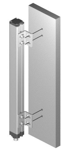
32 Dimensions Figure 27 - Emitter and Receiver Figure 28 - FIE inserts and LE fastening brackets (provided) /12/2017 Rev.21 31
33 Figure 29 - Fastening brackets SFBE Figure 30 - Fastening brackets SFB180E M8 Inserts Model H SP100S 250 SP300S 400 SP400S 540 SP600S 715 SP700S 885 SP900S 1060 SP1100S 1230 SP1200S 1400 SP1300S 1450 SP1500S 1600 SP1600S 1750 SP1800S 1900 Figure 32 - Fastening brackets for mirrors Figure 31 - Deflection mirrors /12/2017 Rev.21
34 CHECKOUTS AND MAINTENANCE Functional checks chapter Figure 33 Efficiency check /12/2017 Rev.21 33
35 Troubleshooting Check connections of pins 2 & 4. Send to REER for repair. Check model compatibility Check condition of the Master. If in FAIL condition, check the type of fault. If the fault persists, send the device to ReeR laboratories for repair. Check Master/Slave connections. Reset of the system. If the fault persists, send Master and Slave to ReeR laboratories for repair Table 19 - Troubleshooting Check connections. Check connections (pin 4). Carefully locate the interfering Emitter and take action in one of the following ways: Reduce the range of the interfering Emitter from High to Low Swap over the position of Emitter and Receiver Move the interfering Emitter so that it does not illuminate the Receiver Shield the beams emitted by the interfering Emitter using opaque protections Check connections. If the fault persists, send to REER for repair. Send the device to ReeR laboratories for repair Check Master/Slave connections If the fault persists, send the device to ReeR laboratories for repair /12/2017 Rev.21
36 /12/2017 Rev.21 35
37 Accessories/Spares /12/2017 Rev.21
38 GUARANTEE Characteristics liable to modifications without prior notice. Complete or partial reproduction is forbidden without REER s prior authorisation /12/2017 Rev.21 37
39 Dichiarazione CE di conformità EC declaration of conformity REER SpA via Carcano Torino Italy Torino, 05/12/2017 dichiara che le barriere fotoelettriche EOS4 sono Dispositivi Elettrosensibili di Sicurezza (ESPE) di : Tipo 4 (secondo la Norma EN :2013; EN :2013) SIL 3 (secondo la Norma IEC (ed.2); IEC : (ed.2); IEC : (ed.2); IEC : (ed.2)) SILCL 3 (secondo la Norma IEC 62061:2005/A2:2015) Cat.4 - PL e (secondo la Norma EN ISO :2015) declares that the EOS4 photoelectric safety barriers are : Type 4 (according the Standard EN :2013; EN :2013) SIL 3 (according the Standard IEC (ed.2); IEC : (ed.2); IEC : (ed.2); IEC : (ed.2)) SILCL 3 (according the Standard IEC 62061:2005/A2:2015) Cat.4 - PL e (according the Standard EN ISO :2015) Electro-sensitive Protective Equipments (ESPE) realizzati in conformità alle seguenti Direttive Europee: complying with the following European Directives: 2006/42/EC "Direttiva Macchine" "Machine Directive" 2014/30/EU "Direttiva Compatibilità Elettromagnetica" "Electromagnetic Compatibility Directive" e alle seguenti Norme: /and to the following Standards: EN 50178: 1997 EN 55022: 2006 EN : 2005 e sono identiche all'esemplare esaminato ed approvato con esame di tipo CE da: and are identical to the specimen examined and approved with a CE - type approval by: TÜV SÜD Product Service GmbH Zertifizierstelle Ridlerstraße München Germany N.B. number: 0123 Certificate No. Z Responsabile per la documentazione tecnica: Responsible person for technical documentation: Carlo Pautasso Carlo Pautasso Direttore Tecnico Technical Director Simone Scaravelli Amministratore Delegato Managing director

40 REER S.p.A. 32 via Carcano Torino Italia Tel. +39/ r.a. Fax +39/ Internet:
PHOTOELECTRIC SAFETY BARRIER EOS4.
 PHOTOELECTRIC SAFETY BARRIER EOS4 INSTALLAZIONE, USO E MANUTENZIONE INSTALLATION, USE AND MAINTENANCE INSTALLATION, UTILISATION ET MAINTENANCE INSTALLATION, BEDIENUNG UND WARTUNG INSTALACIÓN, USO Y MANTENIMIENTO
PHOTOELECTRIC SAFETY BARRIER EOS2.
 PHOTOELECTRIC SAFETY BARRIER EOS2 INSTALLAZIONE, USO E MANUTENZIONE INSTALLATION, USE AND MAINTENANCE INSTALLATION, UTILISATION ET MAINTENANCE INSTALLATION, BEDIENUNG UND WARTUNG INSTALACIÓN, USO Y MANTENIMIENTO
Dichiarazione CE di conformità EC declaration of conformity
 Dichiarazione CE di conformità EC declaration of conformity Torino, 31/08/2015 REER SpA via Carcano 32 10153 Torino Italy dichiara che le barriere fotoelettriche EOS2 sono Dispositivi Elettrosensibili
Dichiarazione CE di conformità EC declaration of conformity
 Dichiarazione CE di conformità EC declaration of conformity Torino, 1/1/2010 REER SpA via Carcano 32 10153 Torino Italy dichiara che le barriere fotoelettriche EOS4 sono Dispositivi Elettrosensibili di
Dichiarazione CE di conformità EC declaration of conformity
 Dichiarazione CE di conformità EC declaration of conformity Torino, 1/1/2010 REER SpA via Carcano 32 10153 Torino Italy dichiara che le barriere fotoelettriche EOS2 sono Dispositivi Elettrosensibili di
Dichiarazione CE di conformità EC declaration of conformity
 Dichiarazione CE di conformità EC declaration of conformity Torino, 1/1/2010 REER SpA via Carcano 2 1015 Torino Italy dichiara che le barriere fotoelettriche EOS sono Dispositivi Elettrosensibili di Sicurezza
Dichiarazione CE di conformità EC declaration of conformity
 Dichiarazione CE di conformità EC declaration of conformity Torino, 1/1/2010 REER SpA via Carcano 32 10153 Torino Italy dichiara che le barriere fotoelettriche EOS4 sono Dispositivi Elettrosensibili di
PHOTOELECTRIC SAFETY BARRIER ADMIRAL.
 PHOTOELECTRIC SAFETY BARRIER MIRAL INSTALLAZIONE, USO E MANUTENZIONE INSTALLATION, USE AND MAINTENANCE INSTALLATION, UTILISATION ET MAINTENANCE INSTALLATION, BEDIENUNG UND WARTUNG INSTALACIÓN, USO Y MANTENIMIENTO
PHOTOELECTRIC SAFETY BARRIER ADMIRAL AX.
 PHOTOELECTRIC SAFETY BARRIER ADMIRAL AX INSTALLAZIONE, USO E MANUTENZIONE INSTALLATION, USE AND MAINTENANCE INSTALLATION, UTILISATION ET MAINTENANCE INSTALLATION, BEDIENUNG UND WARTUNG INSTALACIÓN, USO
Dichiarazione CE di conformità EC declaration of conformity
 Dichiarazione CE di conformità EC declaration of conformity Torino, 05/03/2015 REER SpA via Carcano 32 10153 Torino Italy dichiara che le barriere fotoelettriche VISION sono Dispositivi Elettrosensibili
Dichiarazione CE di conformità EC declaration of conformity
 Dichiarazione CE di conformità EC declaration of conformity Torino, 1/1/2010 REER SpA via Carcano 32 10153 Torino Italy dichiara che le barriere fotoelettriche ADMIRAL sono Dispositivi Elettrosensibili
PHOTOELECTRIC BARRIER ULISSE UPC
 PHOTOELECTRIC BARRIER ULISSE UPC INSTALLAZIONE, USO E MANUTENZIONE INSTALLATION, USE AND MAINTENANCE INSTALLATION UND WARTUNGSANLEITUNG PHOTOELECTRIC BARRIER ULISSE UPC INSTALLATION, USE AND MAINTENANCE
PHOTOELECTRIC BARRIER ULISSE UPC
 PHOTOELECTRIC BARRIER ULISSE UPC INSTALLAZIONE, USO E MANUTENZIONE INSTALLATION, USE AND MAINTENANCE INSTALLATION UND WARTUNGSANLEITUNG Dichiarazione CE di conformità EC declaration of conformity Torino,
Dichiarazione CE di conformità EC declaration of conformity
 Dichiarazione CE di conformità EC declaration of conformity Torino, 1/1/2010 REER SpA via Carcano 32 10153 Torino Italy dichiara che le barriere fotoelettriche MIRAL sono Dispositivi Elettrosensibili di
Dichiarazione CE di conformità EC declaration of conformity
 Dichiarazione CE di conformità EC declaration of conformity Torino, 1/1/2010 REER SpA via Carcano 32 10153 Torino Italy dichiara che le barriere fotoelettriche JANUS sono Dispositivi Elettrosensibili di
Dichiarazione CE di conformità EC declaration of conformity
 Dichiarazione CE di conformità EC declaration of conformity Torino, //2 REER SpA via Carcano 32 53 Torino Italy dichiara che le barriere fotoelettriche JANUS sono Dispositivi Elettrosensibili di Sicurezza
PHOTOELECTRIC SAFETY BARRIER VISION VX INSTALLATION USE AND MAINTENANCE INTRODUCTION... 2 OPERATION... 3 INSTALLATION... 4
 PHOTOELECTRIC SAFETY BARRIER VISION VX INSTALLATION USE AND MAINTENANCE INDICE INTRODUCTION... 2 OPERATION... 3 INSTALLATION... 4 POSITION...5 MASTER/SLAVE POSITIONING...6 SAFETY DISTANCE CALCULATION...7
PHOTOELECTRIC SAFETY BARRIER VISION VXL INSTALLATION USE AND MAINTENANCE INTRODUCTION... 2 OPERATION... 3 INSTALLATION... 4
 PHOTOELECTRIC SAFETY BARRIER VISION VXL INSTALLATION USE AND MAINTENANCE INDICE INTRODUCTION... 2 OPERATION... 3 INSTALLATION... 4 POSITION...5 SAFETY DISTANCE CALCULATION...6 VERTICAL POSITION OF THE
PHOTOELECTRIC SAFETY BARRIER ADMIRAL INSTALLATION USE AND MAINTENANCE INTRODUCTION... 2 OPERATION... 3 INSTALLATION... 4
 PHOTOELECTRIC SAFETY BARRIER MIRAL INSTALLATION USE AND MAINTENANCE TABLE OF CONTENTS INTRODUCTION... 2 OPERATION... 3 INSTALLATION... 4 POSITION...5 SAFETY DISTANCE CALCULATION...6 VERTICAL POSITION OF
Dichiarazione CE di conformità EC declaration of conformity
 Dichiarazione CE di conformità EC declaration of conformity Torino, 22/02/2007 REER SpA via Carcano 32 10153 Torino Italy dichiara che le barriere fotoelettriche METRON sono dispositivi optoelettronici
JANUS MI / MM / ML / MT TRX JANUS MI TRX L / J TRX L
 PHOTOELECTRIC SAFETY BARRIER JANUS MI / MM / ML / MT TRX JANUS MI TRX L / J TRX L INSTALLAZIONE, USO E MANUTENZIONE INSTALLATION, USE AND MAINTENANCE INSTALLATION, UTILISATION ET MAINTENANCE INSTALLATION,
ORIGINAL INSTRUCTIONS
 FACTORY AUTOMATION ORIGINAL INSTRUCTIONS Safety light grid SLP series The latest version of the General Terms of Supply for Products and Services in the Electronics Industry issued by the German Electrical
Original operating instructions Fail-safe inductive sensor GG507S / / 2013
 Original operating instructions Fail-safe inductive sensor GG507S 80005283 / 00 05 / 2013 Contents 1 Preliminary note...3 1.1 Explanation of symbols...3 2 Safety instructions...4 2.1 Safety-related requirements
User Guide. Index PRESSURE TRANSMITTER SX SERIES ENG. II 1GD Ex ia IIC T6 Ex ia IIIC T85 C II 1/2GD Ex ia IIC T6 Ex ia IIIC T85 C
 Industrial instrumentation for Pressure and Temperature ENG User Guide II 1GD Ex ia IIC T6 Ex ia IIIC T85 C II 1/2GD Ex ia IIC T6 Ex ia IIIC T85 C Index 8.1.1 IMPORTANT INFORMATION 2 8.1.2 FUNCTION 2 8.1.3
Safety Light Curtain Orion1 Extended
 Safety Light Curtain Orion1 Extended pprovals: pplication: For finger and hand detection When the light guard should be close to the hazardous zone When muting or blanking are necessary When several devices
SMARTSCAN 8000 SERIES LIGHT CURTAIN Series Safety Light Curtain Installation Sheet (CD159/030210)
") SMARTSCAN 8000 SERIES LIGHT CURTAIN 1 8000 Series Safety Light Curtain Installation Sheet (CD159/030210) Figure A - Unpacking Remove all packaging material and retain it Locate and keep the delivery note
SMARTSCAN 8000 SERIES LIGHT CURTAIN 1 8000 Series Safety Light Curtain Installation Sheet (CD159/030210) Figure A - Unpacking Remove all packaging material and retain it Locate and keep the delivery note
Process/Mini. English IMPORTANT NOTE. Installation and Operation Manual. General Purpose Light Curtain with 30 mm resolution
 Installation and Operation Manual Process/Mini General Purpose Light Curtain with 30 mm resolution English manufactured under ISO 9001: 2000 IMPORTANT NOTE FOLLOW THE INSTRUCTIONS GIVEN IN THIS MANUAL
Safety light curtain to safeguard the hinge edge IMPORTANT NOTE
 Installation and Operation Manual CEDES MicroRay Safety light curtain to safeguard the hinge edge English EN 12978 EN 13849-1 IMPORTANT NOTE FOLLOW THE INSTRUCTIONS GIVEN IN THIS MANUAL CAREFULLY. FAILURE
Original instructions INCA-1 Tina Emergency stop for enclosure installation INCA-1S Tina Safety stop for enclosure installation
 Original instructions INCA-1 Tina Emergency stop for enclosure installation INCA-1S Tina Safety stop for enclosure installation ABB AB / Jokab Safety Varlabergsvägen 11, SE-434 39 Kungsbacka, Sweden www.abb.com/lowvoltage
Original operating instructions Fail-safe inductive sensor GM705S
 Original operating instructions Fail-safe inductive sensor GM705S 80236832 / 00 09 / 2016 Contents 1 Preliminary note...3 1.1 Symbols used...3 1.2 Warning signs used...3 2 Safety instructions...4 2.1 Safety-related
Original operating instructions Fail-safe inductive sensor GM504S / / 2010
 Original operating instructions Fail-safe inductive sensor GM504S 704070 / 01 06 / 2010 Contents 1 Preliminary note 3 1.1 Explanation of symbols 3 2 Safety instructions 4 2.1 Safety-related requirements
Operating instructions Fail-safe delay timer AZS About this document. Content
 8 Appendix 8.1 Wiring example...4 8.2 Integral System Diagnostics (ISD)....5 9 EU Declaration of conformity Operating instructions.............pages 1 to 6 Original x.000 / 11.2017 / v.a. - 101126753-
1000 SERIES INSTALLATION SUPPLEMENT Rev. 7/1/10
 1000 SERIES INSTALLATION SUPPLEMENT Rev. 7/1/10 Smartscan Incorporated 33083 Eight Mile Road Livonia, MI 48152 Phone: (248) 477-2900 Fax: (248) 477-7453 SMARTSCAN INCORPORATED Livonia, MICHIGAN 1000 The
1000 SERIES INSTALLATION SUPPLEMENT Rev
 1000 SERIES INSTALLATION SUPPLEMENT Rev. 1-1-12 Smartscan Incorporated 33083 Eight Mile Road Livonia, MI 48152 Phone: (248) 477-2900 Fax: (248) 477-7453 SMARTSCAN INCORPORATED Livonia, MICHIGAN 1000 The
Wind Direction Transmitter - compact - GMR, analogue output xxx xxx
 THE WORLD OF WEATHER DATA - THE WORLD OF WEATHER DATA - THE WORLD OF WEATHER DATA Instruction for Use 021488/06/09 Wind Direction Transmitter - compact - GMR, analogue output - 4.3129.60.xxx 4.3129.80.xxx
Operating instructions Diffuse reflection sensor with background suppression. OJ51xx laser / / 2010
 Operating instructions Diffuse reflection sensor with background suppression OJ51xx laser 704811 / 00 05 / 2010 Contents 1 Preliminary note3 1.1 Symbols used 3 2 Safety instructions 3 3 Functions and features
Specifications. Safety Ratings. Standards. Safety Classification
 General 1-2-Opto-electronics Safety Switches 4-Emergency Logic Power The Lifeline 4 cable/push button operated system can be installed along or around awkward machinery such as conveyors and provide a
BLG 4A Safety Light Curtain
 User's guide English www.balluff.com Original user's manual All rights reserved. Protected within the legally permissible limits of the United States and internationally. This document may not be copied
MSI-MD-FB Muting Controller
 MSI-MD-FB Muting Controller EN 06/ - 070 We reserve the right to make technical changes S A F E I M P L E M E N T A T I O N A N D O P E R A T I O N O r i g i n a l o p e r a t i n g i n s t r u c t i o
Original operating instructions Fail-safe inductive sensor GG507S
 Original operating instructions Fail-safe inductive sensor GG507S 80236827 / 00 09 / 2016 Contents 1 Preliminary note...3 1.1 Symbols used...3 1.2 Warning signs used...3 2 Safety instructions...4 2.1 Safety-related
SAFETY LIGHT CURTAINS
 , E E with 30 mm resolution and fixed cascade for hand protection for point of operation guarding on presses E with integrated start/restart interlock for access guarding on transport conveyors Rapid market
series. Safety sensor for Palletisers. Features. For Palletiser. 3 Different types available. Active - Passive system and Plug and play
 Safety sensor for Palletisers Features For Palletiser has been developed especially for Palletisers and wrapping machine access protection applications. Active - Passive system and Plug and play By using
Precipitation Monitor ,
 THE WORLD OF WEATHER DATA - THE WORLD OF WEATHER DATA - THE WORLD OF WEATHER DATA Instruction for use 021197/11/09 Precipitation Monitor 5.4103.10.000, 5.4103.10.700 ADOLF THIES GmbH & Co. KG Hauptstraße
Transmitter + Radio Receiver for Target Machine Control. Operating Instructions
 ELFIPA s.n.c. di Fingolo & Papes Piazza 24 Maggio, 6 31040 Gorgo al Monticano (TV) ITALY Tel. +39 0422 800291 Fax +39 0422 800812 www.elfipa.it info@elfipa.it Transmitter + Radio Receiver for Target Machine
RADIOBAND 3G RB3 T868 RB3 R868 USER'S MANUAL
 RADIOBAND 3G RB3 T868 RB3 R868 USER'S MANUAL Index INTRODUCTION... 3 Operating... 3 Receiver RB3 R868... 4 Transmitter RB3 T868... 5 ASSEMBLY AND INSTALLATION... 6 1 Installation of the equipment... 6
Intrinsically Safe Compact Controller CTR 210i. Intrinsically Safe Bargraph Indicator. BGI 210i
 Intrinsically Safe Compact Controller CTR 210i Intrinsically Safe Bargraph Indicator BGI 210i DMT 02 ATEX E 148 2. Supplement also grahics display Revision 4 IBS BatchControl GmbH Im Sträßchen 2 4 Tel.:
TETRIS 1000 High Impedance Active Probe. Instruction Manual
 TETRIS 1000 High Impedance Active Probe Instruction Manual Copyright 2015 PMK GmbH All rights reserved. Information in this publication supersedes that in all previously published material. Specifications
Model OB-ITF Infrared Through-Beam Fiber Optic Optical Barrier Operator s Manual. Version
 Model OB-ITF Infrared Through-Beam Fiber Optic Optical Barrier Operator s Manual Version 11-2010 Contents 1. Introduction... 2 2. Description... 2 2.1 Model Nomenclature... 2 2.2 Operating Principle...
Assembly Instructions
 Assembly Instructions optocontrol 2520 Functions Edge measurement with the shadow principle (Edge low-high; edge high-low) Measurement of diameter-, width-, gap incl. center axis Counting of edges or segments,
3B SCIENTIFIC PHYSICS
 3B SCIENTIFIC PHYSICS Equipment Set for Wave Optics with Laser 1003053 Instruction sheet 06/18 Alf 1. Safety instructions The laser emits visible radiation at a wavelength of 635 nm with a maximum power
INSTRUCTION MANUAL SF4B- G<V2>
 INSTRUCTION MANUAL Light Curtain Type 4 / Heavy-duty SF4B- G (MEMO) Thank you for purchasing Panasonic Electric Works SUNX s Light Curtain, SF4B- G series. Please read this instruction manual carefully
3B SCIENTIFIC PHYSICS
 3B SCIENTIFIC PHYSICS Equipment Set for Wave Optics with Laser U17303 Instruction sheet 10/08 Alf 1. Safety instructions The laser emits visible radiation at a wavelength of 635 nm with a maximum power
FF-SB Series. Type 4 self-contained light curtain For the protection of operators in Industry FF-SB
 Type 4 self-contained light curtain For the protection of operators in Industry FEATURES Meets applicable parts of US OSHA 29CFR 1910.217, 1910.212 and ANSI B11.1, B11.2, B11.19 1990 and RIA 15.06 regulations
DTMA-1800-UMTS-12-AISG
 DTMA--UMTS-12- Double units for easy use with XXPol antennas Suitable for antenna RET control according to /3GPP standard Bypass mode to ensure cell operation in case of power down Supports 1.1 and 2.0
User manual. Load cell with one built in amplifier KOSD-FA KIMD-FA KEND-FA Load cell with two built in amplifiers KOSD-FAD KIMD-FAD KEND-FAD
 User manual Load cell with one built in amplifier KOSD-FA KIMD-FA KEND-FA Load cell with two built in amplifiers KOSD-FAD KIMD-FAD KEND-FAD Contents Precautions Intended use General 1 Specification 3
Safety Light Curtain / Multi-beam Safety Sensor. Sense the Difference, Make a Difference!
 Safety Light Curtain / Multi-beam Safety Sensor F3SN-A/F3SH-A Sense the Difference, Make a Difference! F3SN-A/F3SH-A Safety Light Curtain/Multi-beam Safety Sensor Available Models Specification Safety
DTMA AISG. Fullband Double Dual Duplex Tower Mounted Amplifier (Masthead Amplifier)
") Compact line Double units for easy use with XPol antennas Supports AISG 1.1 and AISG 2.0 (default) Suitable for antenna RET control according to AISG/3GPP standard By-pass mode to ensure cell operation
Compact line Double units for easy use with XPol antennas Supports AISG 1.1 and AISG 2.0 (default) Suitable for antenna RET control according to AISG/3GPP standard By-pass mode to ensure cell operation
The coupling torque at 7-16 connectors is Nm! The tightning torque for fi xing the AISG connector must be Nm!
 Attention: The coupling torque at 7-16 connectors is 25-30 Nm! The tightning torque for fi xing the AISG connector must be 0.5-1 Nm! 936.2179a Änderungen vorbehalten Internet: http://www.kathrein.de Page
Out 1 sin / cos 1Vpp. sin / cos 1Vpp. Out 3. sin / cos 1Vpp. Out 4 sin / cos 1Vpp. Interface type SV211 SinCos signal splitter with 4 SinCos outputs
 Operating Manual Out 1 sin / cos 1Vpp Input: sin / cos 1 Vpp Out 2 sin / cos 1Vpp Out 3 sin / cos 1Vpp SV 211 Out 4 sin / cos 1Vpp Interface type SV211 SinCos signal splitter with 4 SinCos outputs Product
Glossary of terms... P.1549~ General precautions... P panasonic.net/id/pidsx/global
 0 PHOTO PHOTO MEASURE Light Curtain Type SERIES Ver. Related Information Category PLc SIL General terms and conditions... F- SF-C/C...P.~ Type safety solution International regulations for safety measures
RADIOBAND V3 Programming & Installation Manual
 RADIOBAND V3 Programming & Installation Manual Radioband V3 User s Manual Introduction The RadioBand system is designed for Automatic Gates, Commercial and Domestic door applications where a safety edge
SAFETY LIGHT CURTAINS
 SAFETY LIGHT CURTAINS SOLID-, SOLID-E A reliable and interference-proof safety sensor system is a prerequisite for high system availability and achievement of production targets. At the same time the increasing
CCD-array with RTSC. Laserdiode. Multi-lens optics. Filter
 Laser-Wegsensoren optoncdt Options (Triangulation) 2 Table of Contents optoncdt 7-2 / 72-2 / 7-3... 3 optoncdt 7-(6)... optoncdt 7-2... 5 optoncdt 7-2/9... 6 optoncdt 7-2()... 7 optoncdt 22-2(235)... 8
8000 Series Safety Light Curtain Installation Sheet ( CD159/ )
") SMARTSCAN 8000 SERIES LIGHT CURTAIN 1 8000 Series Safety Light Curtain Installation Sheet ( CD159/040305 ) Unpacking Remove all packaging material and retain it Locate and keep the delivery note Inspect
SMARTSCAN 8000 SERIES LIGHT CURTAIN 1 8000 Series Safety Light Curtain Installation Sheet ( CD159/040305 ) Unpacking Remove all packaging material and retain it Locate and keep the delivery note Inspect
Model WHD Weld Hole Detector Operator s Manual. Rev 1.1
 Model WHD Weld Hole Detector Operator s Manual Rev 1.1 Contents 1. Introduction... 2 2. Description... 2 2.1 Model Nomenclature... 2 2.2 Operating Principle... 2 2.3 Specifications... 3 3. Location and
MiniSafe Light Curtains
 r Safety Light Curtains MS600 MS600 MiniSafe Light Curtains Resolution: mm (0. in.), 9 mm (0.7 in.) or 0 mm (.8 in.) resolution Range: 7. m ( ft.) range for the mm resolution, 0 m (6 ft.) range for the
Datasheet - PROTECT-IE-02
 Print - Create PDF - Create EXCEL file 20.04.2011-18:28:57h Datasheet - PROTECT-IE-02 Input expander / PROTECT-IE Input expander Input for up to 4 sensors per interface e.g.: magnetic safety switches type
Built-in Amplifier Photoelectric Sensor
 Built-in Amplifier Photoelectric Sensor Easy-to-use, Low-cost Photoelectric Sensor Incorporating s that can be clearly seen from a distance Conforms to EN and IEC standards Incorporating polarizing function,
Wind Transmitter - compact
 THE WORLD OF WEATHER DATA - THE WORLD OF WEATHER DATA - THE WORLD OF WEATHER DATA Instruction for Use 021194/02/07 Wind Transmitter - compact 4.3518.03.000 4.3519.03.000 ADOLF THIES GmbH & Co. KG Hauptstraße
panasonic-electric-works.net/sunx Type 2 safety solution International regulations for safety measures at reasonable cost
 99 PHOTO PHOTO Curtain Type SERIES Ver. Related Information Ver. General terms and conditions... F- Glossary of terms / General precautions...p.9~ / P.0 selection guide...p.~ SF-C0... P.~ Conforming to
Nivotester FTR325. Technical Information. 1-channel switch amplifier for the microwave barrier Soliwave FDR50/FQR50
 Technical Information Nivotester 1-channel switch amplifier for the microwave barrier Soliwave FDR50/FQR50 Area of application The Nivotester is suitable as a 1-channel switch amplifier for the Soliwave
Catalogue 1SFC en, Edition 3 November 2003 Supersedes Catalogue 1SFC en, Edition 2 November Arc Guard System TVOC
 Catalogue 1SFC 266006-en, Edition 3 November 2003 Supersedes Catalogue 1SFC 266006-en, Edition 2 November 2000 Arc Guard System TVOC System units The two units of the are used as below: Approvals 1. with
DB 112 B. Double Sheet Testing Unit TECHNICAL DESCRIPTION. en / We reserve the right to. make technical changes
 en 03-2014/06 50126540 We reserve the right to make technical changes DB 112 B Double Sheet Testing Unit TECHNICAL DESCRIPTION 2014 Leuze electronic GmbH + Co. KG In der Braike 1 D-73277 Owen / Germany
Wind Transmitter compact xx
 THE WORLD OF WEATHER DATA - THE WORLD OF WEATHER DATA - THE WORLD OF WEATHER DATA Instruction for Use 021075/08/11 Wind Transmitter compact 4.3519.xx.140... 961 ADOLF THIES GmbH & Co. KG Hauptstraße 76
Installation and user s guide H A. NCi-5 non-contact tool setting interface
 Installation and user s guide H-5259-8500-05-A NCi-5 non-contact tool setting interface 1 English Installation and user s guide NCi-5 non-contact tool setting interface This page is intentionally left
Panther. Installation instructions. Receivers PN-R15-1 PN-R15-2 PN-R15-13 PN-R IM-PN-RX103-A03-EN Language: English (original)
") Panther Installation instructions Receivers IM-PN-RX0-A0-EN Language: English (original) PN-R5- PN-R5-2 PN-R5- PN-R5-4 CONTENTS Chapter : CUSTOMER INFORMATION Chapter 2: FUNCTIONAL SAFETY 6 Chapter : PRODUCT
Panther Installation instructions Receivers IM-PN-RX0-A0-EN Language: English (original) PN-R5- PN-R5-2 PN-R5- PN-R5-4 CONTENTS Chapter : CUSTOMER INFORMATION Chapter 2: FUNCTIONAL SAFETY 6 Chapter : PRODUCT
Premier-LC User Guide
 Premier-LC User Guide 1. PRODUCT OPERATION Thank you for purchasing the Premier-LC laser. This emits a red / infra-red spot. If you have any problems or require help when using the Premier-LC laser please
Laser LA-4P. Operating instructions
 Laser LA-4P GB Operating instructions A 1 2 3a 5 3c 3b 3a 4 11 11 6 10 7 14a 14b 14c 12 9 8 B C 2. 1. D E F Ø 50mm - 115 mm Ø 2-4,5 G I K s > 6m > 20ft L M N P1 Q O 13 P2 GB Operating instructions The
Built-in Amplifier Photoelectric Sensor
 Built-in Amplifier Photoelectric Sensor Easy-to-use, Low-cost Photoelectric Sensor Incorporating s that can be clearly seen from a distance Conforms to EN and IEC standards Incorporating polarizing function,
02/11/2015
 Emergency stop and safety guard monitoring 2 channels KNE3-YS Part number 85102436 "Emergency stop" & "Safety gates monitoring" functions Single and 2-channel operation Security with redundancy and feedback
APPLICATIONS. Automotive
 MEASUREMENT light ARRAYS DS2 SERIES The AREAscan family of the DS2 series covers controlled heights ranging from 150 to 2500mm, with 5m operating distances for high resolution versions, or 10m for low
Analogue Demo Multimeter ADM
 Analogue Demo Multimeter ADM 2 3820-0 PHYWE Systeme GmbH & Co. KG Robert-Bosch-Breite 0 D-37079 Göttingen Telefon +49 (0) 55 604-0 Fax +49 (0) 55 604-07 E-mail info@phywe.de Operating instructions The
Industrial motor controller for brushed DC motors 24 VDC
 Industrial motor controller for brushed DC motors 24 VDC Design for output currents up to 5 A Control with the following functions: - reversal of direction of rotation - open-loop speed control (external)
Wind Direction Transmitter First Class analogue output x0.1xx
 THE WORLD OF WEATHER DATA - THE WORLD OF WEATHER DATA - THE WORLD OF WEATHER DATA Instruction for Use 021514/03/09 Wind Direction Transmitter First Class analogue output 4.3150.x0.1xx ADOLF THIES GmbH
40 mm Beam Pitch General Purpose Area Sensor. Failure monitoring
 OTHER SUNX PRODUCTS NA0 SERIES 0 mm Beam Pitch General Purpose Area Sensor Diagnosis Self-diagnosis Interference prevention Slim and intelligent Refer to p.9l for the light curtain. Slim body Failure monitoring
Precipition Sensor with analogue Intensity Output ,
 THE WORLD OF WEATHER DATA - THE WORLD OF WEATHER DATA - THE WORLD OF WEATHER DATA Instruction for use 021335/11/09 Precipition Sensor with analogue Intensity Output 5.4103.20.041, 5.4103.20.741 ADOLF THIES
DA 30 High Torque Technical Specification
 1/17 DA 30 High Torque DA 30-HT-30-5848 2/17 Content 1. General Description... 3 2. Operating Data... 4 3. Performance... 5 4. Materials and Protective Features... 6 5. Dimensions... 6 5.1. Installation
M4000 Standard Curtain and M4000 Advanced Curtain
 ADDENDUM OPERATING INSTRUCTIONS M4000 Standard Curtain and M4000 Advanced Curtain Multiple Light Beam Safety Device en Addendum operating instructions This document is protected by the law of copyright,
02/11/2015
 Emergency stop and safety guard monitoring 1 channel KNAC3-YS Part number 85103035 "Emergency stop" & "Gate monitoring" functions Single channel operation Security with redundancy and feedback circuit
GKT-008 EMI Near Field Probe
 GKT-008 EMI Near Field Probe USER MANUAL GW INSTEK PART NO. 82KT-00800EA1 ISO-9001 CERTIFIED MANUFACTURER This manual contains proprietary information, which is protected by copyright. All rights are reserved.
in one housing (3). The light beam is reflected by a reflector (4). The objects are detected by interruption of the light beam.
. The light beam is reflected by a reflector (4). The objects are detected by interruption of the light beam.") This info card serves as a supplement to the main position sensors catalogue and to the individual data sheets. For further information and contact addresses please visit our homepage at www.ifm. com.
This info card serves as a supplement to the main position sensors catalogue and to the individual data sheets. For further information and contact addresses please visit our homepage at www.ifm. com.
COD GB / 1.0 RBAND/UMS - RBAND/CSM
 INTRODUCTION DESCRIPTION The RadioBand system is designed of Industrial, Commercial and Domestic door and gate applications where a safety edge is used. The system provides a wireless system replacing
5 kn Flexure Fixture. The difference is measurable
 5 kn Flexure Fixture Reference Manual - Equipment M10-82810-11 Revision C The difference is measurable Electromagnetic Compatibility Where applicable, this equipment is designed to comply with International
Wind Transmitter First Class Advanced Classified according to IEC ( )
") THE WORLD OF WEATHER DATA - THE WORLD OF WEATHER DATA - THE WORLD OF WEATHER DATA Instruction for Use 021519/01/09 Wind Transmitter First Class Advanced Classified according to IEC 61400-12-1 (2005-12)
THE WORLD OF WEATHER DATA - THE WORLD OF WEATHER DATA - THE WORLD OF WEATHER DATA Instruction for Use 021519/01/09 Wind Transmitter First Class Advanced Classified according to IEC 61400-12-1 (2005-12)
Measuring current transformers of the W, W series
 Measuring current transformers of the W, W -8000 series W(-8000)_D00078_01_D_XXEN/09.2015 Measuring current transformers of the W, W -8000 series Product description The highly sensitive W and W -8000
! Detection range up to 130 mm. ! Data transmission up to 1.5 MBit/s. ! Devices for PROFIBUS. ! Sturdy aluminium housing
 Data transmission light beam switch! Detection range up to 30 mm! Data transmission up to.5 MBit/s! Devices for PROFIBUS! Easy adjustment by integrated alignment LED and finder scope! Connection with spring-loaded
PD140FNT60QMU-02C. Through Beam. Main features. Description
 Through eam Description The PD140 sensor consists of an emitter, which sends out invisible, infrared light, and a receiver, capable of detecting the light from the emitter. The sensor is encapsulated in
Hygro-ThermoTransmitter-compact xxx
 THE WORLD OF WEATHER DATA - THE WORLD OF WEATHER DATA - THE WORLD OF WEATHER DATA Instruction for use 020891/08/07 Hygro-ThermoTransmitter-compact 1.1005.54.xxx 1.1005.54.000/150/161/461/173 1.1005.54.241/441
All installation operations can only be carried out by qualified technicians who are suitably trained with respect to the relevant norms and laws.
 General instructions 3 1 1.1 General instructions This manual aims at providing information to install the CRS receiving unit of Autec Dynamic series radio remote controls. Instructions regarding the use
F3SN-A & F3SH-A. Safety Light Curtain & Multiple-beam Safety Sensor
 Curtain & Multiple-beam Safety Sensor The Ideal Safety Sensor for Every Application OMRON provides safety two ways: The Curtain and the Multiple-beam Safety Sensor Finger Protection Curtain Operating range: