KIT FOR CAR BRAKE TESTERS SRT047BTH OPERATOR S MANUAL
|
|
|
- Roland Mathews
- 6 years ago
- Views:
Transcription


1 KIT FOR CAR BRAKE TESTERS SRT047BTH OPERATOR S MANUAL
2 CONTENTS 1. INTRODUCTION Description of SRT047BTH Kit Positioning the SRT047BTH Kit CONFIGURATION...3
3 1. INTRODUCTION This manual provides detailed instructions for the customer, for the purpose of connecting the pedal pressure measuring devices on RAVAGLIOLI car brake testers. device functionality is ensured on brake tester systems with FW versions 1.63 or later (the FW version can be read on the first page of the program at lower right and should be available from April 2006, see example in Figure 1). FW version 1.63 Figure 1 IMPORTANT: A number of program parameters need only be changed during first installation of devices. This operation must only be performed by the RAVAGLIOLI S.p.A. skilled technical assistance personnel; for this reason access requires a password. If these parameters are not changed, even if all the following instructions are followed, the device will not work. The measuring devices besides providing excellent transmission, also make it possible to have several units interact in the same environment. The transmitter comes on by pressing the ON key, the red LED comes on. After a few seconds, the transmitter connects with the receiver and this condition is shown by the flashing red LED. To switch off press the OFF key. Switch-off occurs after about 2 sec.; the red LED goes off. Green LED ON key Red LED OFF key When not used, the transmitter goes off automatically, after it has not been connected for a few minutes (e.g., because the console is off) or after a few minutes when no pressure is applied to the cell. When the transmitter is put under charge, the green LED comes on; to ensure charge is correct, the transmitter must be off (red LED off). Page 1/4
")


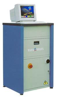
4 2. Description of SRT047BTH Kit 2 1 Figure 2 3 1) Pressure-meter pedal with transmitter 2) Battery charter for the transmitter 3) Receiver to place on the console and connection cable of receiver. 3. Positioning the SRT047BTH Kit Do not position the receiver directly on metal surfaces. In the case of the console units RAVRT009/4S and RAVRT011/4S, remove the thermoformed and position this as shown below, in the inside part, using adhesive supports. Remove the thermoformed and position the receiver in the inside part using adhesive supports RAV RT011/4S RAV RT009/4S Remove the thermoformed and position the receiver in the inside part using adhesive supports Figure 3 The wiring harness must be connected between the on the CPU board inside the console. receiver and the JP14 connector JP14 Figure 4 Page 2/4
.")


5 4. CONFIGURATION The transmitter and the receiver are associated in the factory. On the transmitter and on the receiver, labels are shown indicating the same address (12-figure code). See Figure 5 Same address on receiver and transmitter OFFSET GAIN Figure 5 In case of a fault affecting one of the two, both the transmitter and the receiver will have to be replaced. The transmitter is also factory set and, for this reason, during installation, the Offset and Gain parameters must be attributed. These are shown on the transmitter label. To enter the OFFSET and GAIN values, proceed as follows: Press key F1 from the initial program page (Figure 6). Figure 6 Using key F2 select TECHNICAL ASSISTANCE and press the ENTER/F3 key to confirm selection (Figure 7). Figure 7 Page 3/4
.")
.")

.")
6 Q Using key F2 select BTH DEVICES CONFIGURATION PARAMETERS and press the ENTER/F3 key to confirm selection (Figure 8). Figure 8 Insert the following password: "F2- F2-F3-F3-F4-F4 " Using key F2 select the device to be configured and press ENTER/F3 to confirm selection (Figure 9). The grey icons indicate that the device is not available. Figure 9 Using key F2 select OFFSET and press the ENTER/F3 key to introduce the OFFSET value shown on the transmitter label (Figure 5). Enter the OFFSET value and press ENTER/F3 again to confirm (Figure 10). Using key F2 select GAIN and press ENTER/F3 to enter the GAIN value shown on the label of transmitter (Figure 5). Enter the GAIN value and press ENTER/F3 again to confirm (Figure 10). Figure 10 Press F1 to end procedure and return to initial program page. Page 4/4
uavionix Ping2020 Transceiver
 uavionix Ping2020 Transceiver QUICK START GUIDE Install 1 Install the uavionix Ping App from the Apple App Store or Google Play. Search for uavionix Ping Installer or use the QR codes below. Connect the
CordLift WireFree Programming & Operation Instructions CT-32RT-12V
 New & Improved ming New programming applies to all CordLift WireFree motors released after August 2006. These motors will have new packaging as well as a new colored label on them. Before you begin Motors
Multi-protocol Decoder with load regulation for DC and Faulhaber Motors Features Description
 Multi-protocol Decoder with load regulation for DC and Faulhaber Motors Features Regulated Multi-protocol decoder for DCC, Motorola Suitable for DC and Bell armature motors up to.7a Quiet motor running
Refer to your text book (page 349 to 352) (1) Draw a circuit diagram to represent the wiring in a typical parallel circuit.
 (1) Draw a circuit diagram to represent the wiring in a typical parallel circuit.") SERIES and PARALLEL CIRCUITS Refer to your text book (page 349 to 352) (1) Draw a circuit diagram to represent the wiring in a typical parallel circuit. (2) What are some of the advantages of using parallel
SERIES and PARALLEL CIRCUITS Refer to your text book (page 349 to 352) (1) Draw a circuit diagram to represent the wiring in a typical parallel circuit. (2) What are some of the advantages of using parallel
Blue Point Engineering
 DMX Data Analyzer Board nstruction Overview DMX Analyzer - Tester PC Board Design your own enclosure with an analyzer / tester display or add to your existing equipment or system. The DMX Analyzer is a
Studuino Color Sensor Manual
 Studuino Color Sensor Manual This manual explains the Studuino Programming Environment and how to use it. As the Studuino Programming Environment develops, this manual may be edited or revised. You can
MT3500 Hand-Held Engine Analyzer Safety Operation Regulations
 MT3500 Hand-Held Engine Analyzer Safety Operation Regulations - 1 - Chapter One Introduction A. Notice of Usage: MT3500 Hand-Held Engine Analyzer must be operated by trained professionals, who must know
Programming Manual Washer Extractors Compass Control
 Programming Manual Washer Extractors Compass Control 438 9216-01/EN 07.12 Contents Contents Safety precautions...5 General...7 Engaging servicemode...7 Programming...9 Parameter programming...9 Statistics...14
MAINTAINING OPTIMAL ALARM MONITORING COMMUNICATION
 MAINTAINING OPTIMAL ALARM MONITORING COMMUNICATION 2. MULTIUSER RF, DSSS AND PUBLIC NETWORKS Optimal communication from outstations to the control room is crucial to provide a reliable monitoring service.
Radio receivers type DB317 and DBR1-M4
 Radio receivers type DB317 and DBR1-M4 User manual Art no 006176 Technical data DB317 DBR1-M4 Dimensions (WxHxD) 45x75x21 mm 80x80x50 mm Supply Voltage via control panel 12/24 VAC/VDC Current Consumption
eguard EG2233, EG3333, EG3355, EG3388 & EG8406: Installation and Set-up Procedures Tx 2200 and Rx 4200 Boards
 eguard EG2233, EG3333, EG3355, EG3388 & EG8406: Installation and Set-up Procedures Tx 2200 and Rx 4200 Boards A. Primary Technical Data: Transmitter Operating voltage DC 24V Operating current. < 450mA
IMPORTANT WARRANTY & INSTALLATION INSTRUCTIONS ATTACHED
 IMPORTANT WARRANTY & INSTALLATION INSTRUCTIONS ATTACHED Please Forward All Attached Information to Consumer Warranty Not Valid Unless Returned to Volant Performance STOP Please be sure to review the enclosed
Installation Guide - Addendum Garmin to Contigo 6150 & 6151
 Beacon and Garmin: Dispatch and Navigation The Contigo 6150 & 6151 provide a fleet management interface to Garmin Personal Navigation Devices (PNDs) including the nüvi 2x5, 465, 12xx, 13xx, and 14xx series.
0.01kV (0 to ±0.99 kv)
") Handheld Electrostatic Meter Series IZH10 Easy-to-use handheld electrostatic meter Rated charge amount range: ±20.0 kv Minimum display unit: 0.1kV (±1.0 to ±20.0 kv) Check the current situation before
Handheld Electrostatic Meter Series IZH10 Easy-to-use handheld electrostatic meter Rated charge amount range: ±20.0 kv Minimum display unit: 0.1kV (±1.0 to ±20.0 kv) Check the current situation before
WIRING SCHEMATICS FOR SOFTWARE VERSIONS 5.13 AND HIGHER
 55 S. Vineyard Avenue Ontario, CA 976 (909) 93-973 WIRING SCHEMATICS FOR SOFTWARE VERSIONS 5.3 AND HIGHER FOR CURTIS 39 CONTROLLER ON-ROAD VEHICLE CONVERSION FOR SINGLE AND WITH DUAL MOTOR APPLICATIONS
USER S MANUAL. Manual for Panel Mount Process Indicator. HTA INSTRUMENTATION (P) LTD. Your One Stop for Instrumentation, Calibration & Service
 LTD. Your One Stop for Instrumentation, Calibration & Service") Member of SN Registrars (Holdings) Ltd 8327 USER S MANUAL Manual for Panel Mount Process Indicator EQ-DS8B-IRRB EQ-DS8B-IRRB HTA INSTRUMENTATION (P) LTD. Your One Stop for Instrumentation, Calibration
Member of SN Registrars (Holdings) Ltd 8327 USER S MANUAL Manual for Panel Mount Process Indicator EQ-DS8B-IRRB EQ-DS8B-IRRB HTA INSTRUMENTATION (P) LTD. Your One Stop for Instrumentation, Calibration
1090i. uavionix Ping1090i Transceiver QUICK START GUIDE
 1090i uavionix Ping1090i Transceiver QUICK START GUIDE Install 1 Install the uavionix Ping App from the Apple App Store or Google Play. Search for uavionix Ping Installer or use the QR codes below. Connect
Industrial Systems Design & Implementation
 Industrial Systems Design & Implementation * Is no larger than a packet of cigarettes, and does not need batteries. Comes with two test cables, and extensive documentation with instructions and examples
Installation Instructions. RFID MHz Interface Board for EasyCoder F2 and F4 Printers
 Installation Instructions RFID 13.56 MHz Interface Board for EasyCoder F2 and F4 Printers Information in this manual is subject to change without prior notice and does not represent a commitment on the
NEO CAR AUDIO. Neo AUXiN AUX INPUT INTERFACE. Instruction Manual
 NEO CAR AUDIO Neo AUXiN AUX INPUT INTERFACE Instruction Manual IMPORTANT NOTE Neo AUXiN Dip switch positions MUST be set BEFORE any other step is taken. Otherwise, the kit will not operate properly. See
Installation & Operation Manual SAGA1-K Series Industrial Radio Remote Control
 Installation & Operation Manual SAGA1-K Series Industrial Radio Remote Control Gain Electronic Co. Ltd. Table Of Contents Safety Considerations ------------------------------------------------------------2
CONSTRUCTIVE DOCUMENTATION 09/06/2003 WIRING. Dash ST1. Logger s pinout. How to power the gauge
 AIM DashST1 CONSTRUCTIVE DOCUMENTATION 09/06/2003 WIRING Notes: general-purpose wiring for Dash ST1. Version 1.01 Dash ST1 167 [6.57] GEAR 87 [3.43] 27 [1.06] x1000 rpm mod.416tg Dimensions in millimetres
Optical Return Loss testing
 Optical Return Loss testing using KI 7340 series Loss Tester Kingfisher International PTY LTD www.kingfisher.com.au V 040701 General feature summary No warm up: Two-Way Loss, Source, Meter & ORL tester
LESLIE CONSOLE CONNECTOR KIT 7043 INSTALLATION INSTRUCTIONS
 LESLIE CONSOLE CONNECTOR KIT 7043 INSTALLATION INSTRUCTIONS FOR USE WITH: LESLIE Speaker Models: 125, 225, 145, 147, 147RV, 247, 247RV WURLITZER Organ Models: 4300, 4500, 4520 MULTIPLE SPEAKER INSTALLATION:
IMPORTANT! Please take the time to read through the manual before you start to install/program your equipment.
 PRODUCT DESCRIPTION IMPORTANT! Please take the time to read through the manual before you start to install/program your equipment. The systems KRC11, 12, 13 and 14 consists of two parts: the transmitter
Operator s Manual Ride-On Remote Controlled Car
 Operator s Manual Ride-On Remote Controlled Car By Kevin Franzino Kelly O Neill Jeffrey Peterson Project for Client #14: Samantha Gillard Client Contacts: Geoff and Jenny Gillard: Newton, MA 617 447-0783;
UF-7 INSTALLATION INSTRUCTIONS UF-7. Universal Hobby Lighting Controller. Installation Instructions.
 UF-7 INSTALLATI INSTRUCTIS UF-7 Universal Hobby Lighting Controller Installation Instructions STEP 1 INSTALL LEDS UF-7 INSTALLATI INSTRUCTIS A. Choose where you want to install the LEDs. Next, choose the
Connect + compatible
 Connect + compatible Looking for a quick setup up guide? There is lots of useful information in this book, but if all you are after is quick set up look for the following headings in this book 1) Setting
RFS 2. Operating instructions Bedienungsanleitung Mode d emploi
 RFS 2 Operating instructions Bedienungsanleitung Mode d emploi scope OF delivery 1 11 3 10 2 12 4 5 6 7 8 9 1 case 2 lithium button cell li-mn cr2450 (560 mah, 3 V) 3 display 4 usb socket 5 Sync in 6 Sync
Quick Start Instructions EMV-INspektor V2
 Connecting the : The illustration below shows the connection diagram for the. Step 1: Before connecting the to the voltage supply, first establish the connection of the to the measuring clamp adapters.
2005 Toyota RAV ACCESSORIES & EQUIPMENT Defogger System - RAV4 LOCATION
 2005 ACCESSORIES & EQUIPMENT Defogger System - RAV4 LOCATION Fig. 1: Identifying Defogger System Component Locations INSPECTION 1. CHECK DEFOGGER SWITCH CIRCUIT Disconnect the connector from the heater
MTC-2 highlight features: ACU highlight features: Contents. MTC-2 and ACU User Manual V5.1
 MTC-2 can work alone as a twin motor ECS (electronic speed controller) for RC tanks. When the ACU (auxiliary control unit) is connected, it can also control turret rotation, gun elevation, gun firing,
Section 1 Low power. Laser exchange. Procedure before replacing the laser cartridge
 Laser exchange Procedure before replacing the laser cartridge Section 1. Low Power Section 2. No Beam Section 3. Intermittent Section 4. Poor Engraving Quality Section 5. No red pointer Section 1 Low power
RF Remote Control Unit SEAV
 RF Remote Control Unit SEAV for LINAK TECH-systems Installation instructions Foreword Dear producer, Thank you for choosing an actuator system from LINAK. LINAK systems consist of high-tech products based
Bi-Color Signal Mirror Installation Instructions
 Bi-Color Signal Mirror Installation Instructions 2005-2009 Toyota Tacoma THE safety accessory of the 21 st Century. P/N 210-0141-0 Rev. A2 (3/30/09), BTV 2007 Muth Mirror Systems, LLC Page 3 of 13PplPage
TOYOTA TACOMA 2005 TRAILER WIRE HARNESS Preparation
 Preparation Part Number: 08921 04960 NOTE: Part number of this accessory may not be the same as the part number shown. Kit Contents Item # Quantity Reqd. Description 1 1 Converter Assembl y 2 1 Wire Harness
Instruction Manual for the Software of ASSAN V2 Series Receiver
 Instruction Manual for the Software of ASSAN V2 Series Receiver I. Setup 1. Double click SETUP to enter the welcome interface and click Next. 2. Enter your name and company name and click Next. 3. Select
INTEGRATED VOICE EVACUATION SYSTEM VM-3000 Series
 OPERATION MANUAL INTEGRATED VOICE EVACUATION SYSTEM VM-3000 Series VOICE ALARM SYSTEM AMPLIFIER VM-3240VA VOICE ALARM SYSTEM AMPLIFIER VM-3360VA VM EXTENSION AMPLIFIER VM-3240E VM EXTENSION AMPLIFIER VM-3360E
GESTRA Steam Systems LRS English. Installation & Operating Instructions Conductivity Switch LRS 1-50
 GESTRA Steam Systems LRS 1-50 EN English Installation & Operating Instructions 819223-02 Conductivity Switch LRS 1-50 Contents Important notes Page Usage for the intended purpose...4 Function...4 Safety
TOYOTA TACOMA TRAILER WIRE HARNESS Preparation
 Preparation Part Number: PT725-35120 Kit Contents Item Quantity Reqd. Description # 1 1 Flasher Assembly (F/A) 2 1 Wire Harness 3 1 Sub Wire Harness 4 2 Plastic Tie (300mm) 5 4 Plastic Tie (200mm) 6 13
Two-Way Radios. Quick Start Guide. XT460 Display model
 Two-Way Radios Quick Start Guide XT460 Display model CONTENTS Contents..................................... 1 Safety....................................... 2 Batteries and Chargers Safety Information........
Heritage MedCall. Sentry E-Call Model HM-527 Resident Host Panel
 Heritage MedCall Sentry E-Call Model HM-527 Resident Host Panel 430-527B 0305 Heritage MedCall, Inc. Issue 1, March 2005 Heritage Medcall Sentry Emergency Call System Model 527 Host Panel Installation
Detcon Model FP Transmitter Test Fixture Operators Instruction Manual June 17, 2008 * Document 3389 * Revision 1.1
 Operators Instruction Manual June 17, 2008 * Document 3389 * Revision 1.1 DETCON, Inc. 3200 Research Forest Dr., Building A-1 The Woodlands, Texas 77387 Ph. 713-559-9200 / Fax 281-298-2868 www.detcon.com
Quick Start Guide. Contents
 1 Quick Start Guide Contents Powering on the Machine Login/Password Entry Jaw Set Up High Security Cut by Code High Security Jaw Set Up Edge Cut Cut by Code Edge Cut Cut by Decode Cutter Replacement Tracer
SENNHEISER RADIO MICROPHONE SYSTEM
 SENNHEISER RADIO MICROPHONE SYSTEM This system has been purchased by the trust for the benefit of the local community in Elmbridge and is available on loan for a modest fee to cover running costs and which
Operation. Section 4. Additional Information. Operation 4-1
 4-1 Section 4 WARNING: Allow only personnel with appropriate training and experience to operate or service the equipment. The use of untrained or inexperienced personnel to operate or service the equipment
IMPORTANT: READ AND UNDERSTAND ALL INSTRUCTIONS BEFORE BEGINNING INSTALLATION
 INSTALLATI INSTRUCTIS Model: RB-G-K10 IMPORTANT: READ AND UNDERSTAND ALL INSTRUCTIS BEFORE BEGINNING INSTALLATI The Miller Edge RBand Monitored Gate Edge Transmitter/Receiver system is intended to provide
Instruction Sheet P/N B Trim the new RTD wires. 5. Coat the new RTD with. 4. Strip the ends of the existing
 Instruction Sheet P/N 1029716B 02 RTD Service Kit - P/N 1028320 02/08 Use this service kit to replace either the tank or the manifold RTD on any ProBluet or Mesat adhesive melter. If you are replacing
MTC-2 highlight features: ACU highlight features: Contents. MTC-2 and ACU User Manual V4.0
 MTC-2 can work alone as a twin motor ECS (electronic speed controller) for RC tanks. When the ACU (auxiliary control unit) is connected, it can also control turret rotation, gun elevation, gun firing,
CP7039+CP3039 User Manual
 CP7039+CP3039 User Manual TX:CP7039 RX:CP3039 Antenna Antenna WIFI indicator Low battery indicator WIFI indicator Low battery indicator OLED display screen Audio in OLED display screen Reset Key Mini Hdmi
Introduction...1 Overview...2. Beacon Transmitter...7. Beacon Receiver Trouble Shooting...15
 MoTeC Lap Beacon Manual Contents Introduction...1 Overview...2 Operation...2 ID Number...3 Lap Beacon Use...4 Split Beacon Use...4 Verifying Operation...5 Beacon Transmitter...7 Position...7 Spacing between
Ins GD-US. 3G Modem Installation Guide
 Ins-60007-GD-US 3G Modem Installation Guide Mobile Reception Test To check mobile reception either use a mobile GPRS signal strength tester such as the Sequoia SWGPRS023 device, Wilson Electronics 460118
DVBCommunity - cообщество профессионалов ЦТВ CP7039+CP3039 User Manual
 CP7039+CP3039 User Manual TX:CP7039 RX:CP3039 Antenna Antenna WIFI indicator Low battery indicator WIFI indicator Low battery indicator OLED display screen Audio in OLED display screen Reset Key Mini Hdmi
RADIO ANTI TWO-BLOCK SYSTEM
 BB-550 TM RADIO ANTI TWO-BLOCK SYSTEM INSTALLATION MANUAL GREER Company 1918 East Glenwood Place, Santa Ana, CA 92705 Tel: (714) 259-9702 FAX (714) 259-7626 BB-550 TM Radio Anti Two-Block System PN W250000
Signal Mirror Installation Instructions
 Signal Mirror Installation Instructions Toyota RAV4 1996-2000 THE safety accessory of the 21 st Century. P/N 210-0034-0 Rev B1 (11-19-02), GG 2002 Muth Co. LLC. Note: Professional Installation Recommended
RD1000 Ground Probing Radar
 RD1000 Ground Probing Radar CONTENTS Product Introduction Product Features Competitor Analysis Customers Models, Pricing & Availability Promotional Material Practical Demonstration What to do now Summary
TO.GO 2VA TO.GO 4VA TO.GO 2AS TO.GO 2A TO.GO 2AK TO.GO 4AK TO.GO 2QV TO.GO 4QV TO.GO 4ASE PROGRAMMING GUIDE
 TO.GO 2A TO.GO 4A TO.GO 2VA TO.GO 4VA TO.GO 2AS TO.GO 4AS TO.GO 2AK TO.GO 4AK PROGRAMMING GUIDE TO.GO 4ASE TO.GO 2QV TO.GO 4QV INDEX TECHNICAL SPECIFICATIONS...2 ADVANCED ROLLING-CODE (ARC) 128 BIT...3
CHC i80 GNSS Receiver QuickTour with LandStar7. (PDA Network Mode)
") CHC i80 GNSS Receiver QuickTour with LandStar7 (PDA Network Mode) 1.Prerequisites Hardware: CHC i80 rover, Controller Kit, SIM card,lithium Battery, pole Software: LandStar7 2.Steps to set i80 working
CHC i80 GNSS Receiver QuickTour with LandStar7 (PDA Network Mode) 1.Prerequisites Hardware: CHC i80 rover, Controller Kit, SIM card,lithium Battery, pole Software: LandStar7 2.Steps to set i80 working
BMW E90 Android Touch Screen Radio Installation Instructions
 BMW E90 Android Touch Screen Radio Installation Instructions Enjoy your new Android Radio from Bremmen Parts, we appreciate your business. Vibrant Touch Display This radio features a responsive 9 touch
Experiment P-24 Circuits and Series Resistance
 1 Experiment P-24 Circuits and Series Resistance Objectives To study the relationship between the voltage applied to a given resistor and the intensity of the current running through it. Modules and Sensors
broadcast without limits. user manuel
 broadcast without limits. user manuel TRANSMITTER FS-7039 RECEIVER FS-3039 Freestream App Installation Easily download the Freestream app within the App Store or Google Play. System Requirements: ipad
Wire Harness Installation Instructions For Installing:
 Wire Harness Installation Instructions For Installing: Part # 30713 1974-1977 Camaro Tail Light Harness Perfect Performance Products, LLC Painless Performance Products Division 2501 Ludelle Street Fort
Manual Electric Air-Module 2-14 S with Vario Graupner HoTT 2.4
 Manual 33620 Electric Air-Module 2-14 S with Vario Graupner HoTT 2.4 CONTENTS: 1. Description... 01 2. Mounting the module in the plane... 01 3. Quick Guide... 02 3.1. Connection of sensors... 03 4. Starting
Wireless Analog Output Modules
 Overview and Product Identification Wireless Analog s Analog s receive data from a BAPI 418 MHz receiver or 900 MHz receiver through a four-wire RS 485 bus. Up to 127 different Analog s can be connected
IMPORTANT: THIS DEVICE MUST BE PROFESSIONALLY INSTALLED. READ AND UNDERSTAND ALL INSTRUCTIONS BEFORE BEGINNING INSTALLATION.
 INSTALLATI INSTRUCTIS Model: RB-G-K10 IMPORTANT: THIS DEVICE MUST BE PROFESSIALLY INSTALLED. READ AND UNDERSTAND ALL INSTRUCTIS BEFORE BEGINNING INSTALLATI. The Miller Edge RBand Monitored Gate Edge Transmitter/Receiver
* * APPLICABLE MODELS: 2014 > MAZDA 3
 PART NUMBER: 0000 8C L46 GENUINE ACCESSORIES INSTALLATION INSTRUCTIONS Rev. AAA *550-0604-000* APPLICABLE MODELS: 204 > MAZDA 3 REQUIRED COMPONENTS: ITEM QTY DESCRIPTION Usage Chart MIRROR ASSEMBLY: Mirror
Dual Band Filter Assembly Manual
 Dual Band Filter Assembly Manual 12 January 2018 Rev D Version Theory of Operation: The purpose of a Bandpass Filter is to filter out or reject all unwanted signals. The original KN-Q7A Receive Filter
Courtesy of:discountcarstereo.com USB-BKR. Quick Start Installation Guide for Becker AUX Ready Radios. Works on Becker radios with AUX menu option
 Courtesy of:discountcarstereo.com USB-BKR Quick Start Installation Guide for Becker AUX Ready Radios Works on Becker radios with AUX menu option Revised: January 19, 2018 Introduction: Just because you
Fluke 125. Getting Started. Industrial ScopeMeter
 Fluke 125 Industrial ScopeMeter Getting Started GB Dec 2006, Rev. 1, 09/2009 2006, 2009 Fluke Corporation, All rights reserved. Printed in The Netherlands All product names are trademarks of their respective
ISA GENERAL POINTS 1.1 Modes 1.2 Pushbuttons 1) Pushbutton C (Crown) 2) Pushbutton A 3) Pushbutton B 4) Pushbutton D
 Pushbutton C (Crown) 2) Pushbutton A 3) Pushbutton B 4) Pushbutton D") ISA 9001 1. GENERAL POINTS 1.1 Modes 1.2 Pushbuttons 1) Pushbutton C (Crown) 2) Pushbutton A 3) Pushbutton B 4) Pushbutton D 2. MODES DESCRIPTION 2.1 TIME1 mode (Local time zone) 2.2 Date mode 2.3 Week
ISA 9001 1. GENERAL POINTS 1.1 Modes 1.2 Pushbuttons 1) Pushbutton C (Crown) 2) Pushbutton A 3) Pushbutton B 4) Pushbutton D 2. MODES DESCRIPTION 2.1 TIME1 mode (Local time zone) 2.2 Date mode 2.3 Week
Advanced Test Equipment Rentals
 Established 1981 Advanced Test Equipment Rentals Solmetric PVA-600 PV Analyzer Quick Start Guide www.atecorp.com 800-404-ATEC (2832) : When using the wireless PVA Sensor Kit or manual sensors, the end
Installation Data. Recordall Transmitter Register (RTR ) Remote Electronic Display (RED) SUGGESTED TOOLS MISCELLANEOUS PARTS PROVIDED
 Remote Electronic Display (RED) SUGGESTED TOOLS MISCELLANEOUS PARTS PROVIDED") Recordall Transmitter Register (RTR ) Remote Electronic Display (RED) SUGGESTED TOOLS Electric Drill 3/16 Carbide Tip Masonry Drills Screw Driver Wire Stripper T-10 Stapler with Cable Attachment 59983-001
Recordall Transmitter Register (RTR ) Remote Electronic Display (RED) SUGGESTED TOOLS Electric Drill 3/16 Carbide Tip Masonry Drills Screw Driver Wire Stripper T-10 Stapler with Cable Attachment 59983-001
Installation instructions, accessories. TV receiver, digital
 Installation instructions, accessories Instruction No 30756561 Version 1.1 5 Part. No. 30756181, 30756569 TV receiver, digital Volvo Car Corporation TV receiver, digital- 30756561 - V1.1 Page 1 / 36 Equipment
FRA Interface FRA Technical specifications
 FRA - 1 - FRA Interface Besides the impedance measuring capabilities of the electrochemical workstations IM6/Zennium themselves, the workstations offer the feature to acquire the frequency response of
Photoelectrics Amplifier, µ-processor Controlled Type PAM, 2-10 Inputs/2-10 Transistor Outputs
 Photoelectrics, µ-processor Controlled Type PAM, 2-10 Inputs/2-10 Transistor Outputs µ-processor controlled unit for up to 10 sets of photoelectric sensors Up to 10 independent outputs Self-diagnostic
Experiment P-10 Ohm's Law
 1 Experiment P-10 Ohm's Law Objectives To study the relationship between the voltage applied to a given resistor and the intensity of the current running through it. Modules and Sensors PC + NeuLog application
Wire Harness Installation Instructions For Installing:
 Wire Harness Installation Instructions For Installing: Part # 30714 1978-1981 Camaro Tail Light Harness Perfect Performance Products, LLC Painless Performance Products Division 2501 Ludelle Street Fort
LCC-100 software User manual
 User Manual Pressure Temperature Humidity Air Velocity Airflow Sound level New LCC-100 software User manual Configuration software for Monostats - Class 50 and 100 units - ranges - relays - set points
Installation Instructions Road King Classic Saddlebag Bezels
 Installation Instructions Road King Classic Saddlebag Bezels Thank you for your purchase of Bagger Audio Road King Classic Saddlebag Bezels for your Harley-Davidson motorcycle. We have carefully engineered
Installation Manual Mobile Integration System
 Installation Manual Mobile Integration System Table of Contents Kit Contents... 2 Overview... 3 Installation Instructions... 6 Power up... 12 Test the System... 13 Beam Coverage... 14 Trouble Shooting
SAFETY OFFICER A R E S. Amateur Radio Emergency Communications. IMS For Amateur Radio. Self Study Training Course. Amateur Radio Emergency Service
 AR-IMS-033 Self Study Training Course Amateur Radio Emergency Communications A R E S Amateur Radio Emergency Service IMS For Amateur Radio SAFETY OFFICER Prepared By: Peter Gamble VE3BQP Last Change: 2011-04-07
WPE 48N USER MANUAL Version1.1
 Version1.1 Security instructions 1. Read this manual carefully. 2. Follow all instructions and warnings. 3. Only use accessories specified by WORK PRO. 4. Follow the safety instructions of your country.
IMPORTANT WARRANTY & INSTALLATION INSTRUCTIONS ATTACHED
 IMPORTANT WARRANTY & INSTALLATION INSTRUCTIONS ATTACHED Please Forward All Attached Information to Consumer Warranty Not Valid Unless Returned to Volant Performance STOP For Full-Color Installation Instructions
Instruction Manual. for Media Monkey. 1
 TM TM Instruction Manual for Media Monkey www.audioaperemote.com 1 Congratulations on acquiring your fine Audio Ape product Let s dive right in, getting up and running is a snap. Here are the components:
MONO AMPLIFIER KIT ESSENTIAL INFORMATION. Version 3.0 CREATE YOUR OWN SPEAKER DOCK WITH THIS
 ESSENTIAL INFORMATION BUILD INSTRUCTIONS CHECKING YOUR PCB & FAULT-FINDING MECHANICAL DETAILS HOW THE KIT WORKS CREATE YOUR OWN SPEAKER DOCK WITH THIS MONO AMPLIFIER KIT Version 3.0 Build Instructions
Repairing your Porsche 928 Central Warning System (CWS) controller
 controller") Repairing your Porsche 928 Central Warning System (CWS) controller Disclaimer: This procedure is for a 1984 Porsche 928 S controller. Overview: Under the left foot pedal (dead pedal) of the Porsche 928
Repairing your Porsche 928 Central Warning System (CWS) controller Disclaimer: This procedure is for a 1984 Porsche 928 S controller. Overview: Under the left foot pedal (dead pedal) of the Porsche 928
This product is intended for off-road use. TurboTweak cannot be held responsible for any damage resulting from the use of this product.
 Custom Chip for Turbo Buick / Turbo TA Please read before installing! 1. Before installing the chip, disconnect the power to the ECM by unplugging the orange wire with the black connector by the battery.
1: Introduction : Caution : Tips for Reading this Manual : Preface : System Highlights : Receiver
 1: Introduction....1 1 2: Caution.... 2 2 3: Tips for Reading this Manual....3 3 4: Preface....4 4 5: System Highlights....6 6 6: Receiver..7 7 6.1: Specifications......7 7 6.2: Receiver Operation... 7
IMPORTANT WARRANTY & INSTALLATION INSTRUCTIONS ATTACHED
 IMPORTANT WARRANTY & INSTALLATION INSTRUCTIONS ATTACHED Please Forward All Attached Information to Consumer Warranty Not Valid Unless Returned to Volant Performance STOP For Full-Color Installation Instructions,
INSTALLATION AND OPERATION MANUAL
 RADIO/CAN REMOTE CONTROL SYSTEM -PRELIMINARY- INSTALLATION AND OPERATION MANUAL SDP GREEN 3B1151AJ.doc September 3, 2009 AP INDEX DESCRIPTION... 2 TRANSMITTER AND RECEIVER SYNCHRONIZATION... 3 INDICATOR
DIS-5010A, DIA-512A. Data Acquisition System for Crash Test AUTOMOTIVE TEST EQUIPMENT
 , Data Acquisition System for Crash Test 5-40 On-vehicle Data Logger for Crash Test On-vehicle Airbag Timer for Crash Test On-vehicle Data Logger for Crash Test On-vehicle unit designed to acquire 32 channels
MTC-2 highlight features: ACU for Flakpanzer Gepard highlight features: Contents. MTC-2 and ACU User Manual V4.2 (Flakpanzer Gepard Version)
") This manual is written for the ACU for Flakpanzer Gepard. There are some modifications on usage of servo and LED ports. Please also notice that GSU (gun stabilize unit) is not supported. MTC-2 highlight
This manual is written for the ACU for Flakpanzer Gepard. There are some modifications on usage of servo and LED ports. Please also notice that GSU (gun stabilize unit) is not supported. MTC-2 highlight
IS7705. Installation & Operation Manual AUDIO INTEGRATION KIT. TranzIt LINK
 GET CONNECTED Installation & Operation Manual AUDIO INTEGRATION KIT IS7705 Note to Readers, The information contained within the following documentation is subject to change without notice. Features discussed
HI 2204LT Loop Powered Level Weight Transmitter OPERATION AND INSTALLATION MANUAL
 Loop Powered Level Weight Transmitter OPERATION AND INSTALLATION MANUAL Corporate Headquarters 9440 Carroll Park Drive San Diego, CA 92121 Phone: (858) 278-2900 FAX: (858) 278-6700 Web-Site: http://www.hardysolutions.com
Courtesy of:discountcarstereo.com IL-BKR. Quick Start Installation Guide for Becker AUX Ready Radios. Created: June 9, 2013 Revised: January 19, 2018
 Courtesy of:discountcarstereo.com IL-BKR Quick Start Installation Guide for Becker AUX Ready Radios Created: June 9, 2013 Revised: January 19, 2018 Introduction: Just because you drive an older car does
S ENSORLINK INSTALLATION MANUAL
 S ENSORLINK INSTALLATION MANUAL The SensorLink Transmitter (#7610) and SensorLink Receiver (#7611) are designed to work with Davis Instruments Weather Monitor II and the Weather Wizard III to enable wireless
TOSVERT VF-PS1 series BACnet option unit Instruction Manual BCN001Z
 TOSVERT VF-PS1 series BACnet option unit Instruction Manual BCN001Z NOTICE 1. Make sure that this instruction manual is delivered to the end user of BACnet Option unit. 2. Read this manual before installing
ENCODING PHOTOCELLS MF6
 ENCODING PHOTOCELLS MF6 Wall-mounted encoding photocells, 180 rotation and range of up to 20 mt. The code for the transmitted signal, which must be set at the time of installation, makes it possible to
P2122. P Accelerator Pedal Position Sensor 1 Circuit Low
 Page 1 of 10 Home Account Contact ALLDATA Log Out Help DAN GRIMWOOD DAN GRIMWOOD00002 Select Vehicle New TSBs Technician's Reference Component Search: OK 2006 Dodge Truck RAM 1500 Truck 2WD V8-5.7L VIN
COFDM Multifunctional Receiver Operation Instructions
 COFDM Multifunctional Receiver Operation Instructions Chapter Ⅰ (1) stand a good receiving antenna. Sucker whip antenna on the outside or the roof as possible, try to rod-shaped antenna mounted on the