1: Introduction : Caution : Tips for Reading this Manual : Preface : System Highlights : Receiver
|
|
|
- Gwen Davidson
- 5 years ago
- Views:
Transcription


1
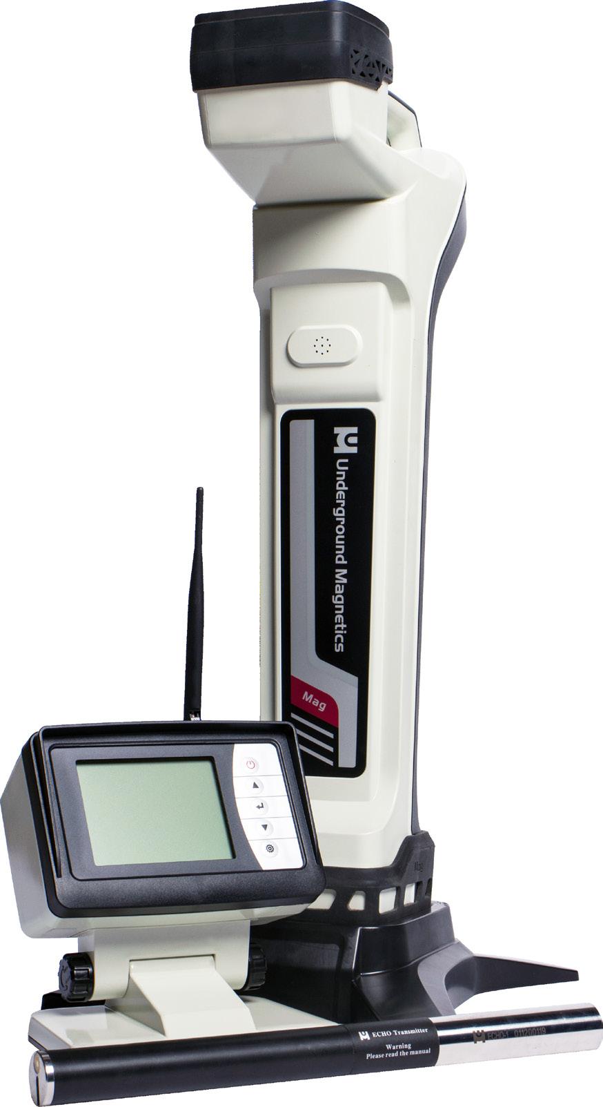
2 1: Introduction : Caution : Tips for Reading this Manual : Preface : System Highlights : Receiver : Specifications : Receiver Operation : Icons : Main Page Icons : Secondary Page Icons : Calibrations and Depth Forecast Page Icons : Setup Page Icons : Calibration : Depth Calibration : Roll Calibration : Operation : Depth Prediction : Transmitter Activation : Transmitter Settings : Receiver Settings : Radio Channel Selection : Pairing : Pitch Unit Selection : Depth Unit Selection : Time Setting : System Unlock : Visibility Control : Receiver Maintenance 26
3 7: Display : Specifications : Display Operations : Icons : Main Page Icons : Secondary Page Icons : Setup Page Icons : Radio Channel Selection : Pairing : Pitch Unit Selection : Distance Unit Selection : Visibility Control : Display Maintenance : Transmitter : Introduction : Specifications : Digital Information : Transmitter Maintenance 37 9: Locating Methods : Locating Basics : Locate Points and Locate Line : Finding the Front Locate Point : Finding the Rear Locate Point : Finding the Locate Line and Transmitter : Locating on the Fly : Bore-To : Battery and Charger : Warranty : Product List... 52
4 The MAG 3 is a locating system designed to assist horizontal directional drill machine operators in locating and tracking underground drill head locations and orientations. The system consists of a transmitter, a receiver, and a remote display. The transmitter sends digital information of the transmitter s pitch, roll, temperature, and battery status through an FM modulated RF signal. The receiver receives this information and uses RF signal to identify the transmitter s status and location. The receiver transmits the locating information to a remote display through a radio telemetry system. A horizontal directional drill machine operator can use the information from the display to guide the drill head to the desired path. This locating system also offers four channel license free radio telemetries between the receiver and remote display. The user can easily pair any two receivers and displays so that communications between the pair will not be interfered by other pairs. This manual is intended to provide information and instructions on how to use this locating system properly. Underground Magnetics Inc. (UM) reserves the right to improve the locating system and the Operator s Manual at any time without notice. Page 1
5 The operator must understand safety procedures and correct operation methods before operating the HDD and the locating system. HDD machines can cause property damage and personal injury upon striking underground power lines, gas lines, phone lines, television cables, fiber optic cables, or sewage lines. Make sure to confirm and mark all underground utilities before beginning operations. Do not use the locating system near flammable or explosive substances. Wear proper personal protective equipment including steel-toed boots, safety gloves, helmets, reflective vests, and safety goggles. Obey all local safety regulations. This locating system is only a tool to assist the operator to locate the drill head. It is the operator, not the Mag 3 locating system that is responsible for identifying the drill head location. UM is not responsible for any damage or loss caused by using the Mag 3 system. Operators should operate the Mag 3 system according to the manual. If there are any questions, please contact UM at support@undergroundmagnetics.com or call customer service at Page 2
6 Here are some points to keep in mind as you read through the Mag 3 Operator s Manual. Page References This question mark and textbox will tell you the page in the Operator s Manual where you can find more detailed information on the corresponding topic. Page X The following two pages contain a short preface. This will be a quick introduction to the steps in which you will most likely use your Mag 3 System. It will also contain page references for the later sections of the manual that contain more detailed information for the corresponding steps. The rest of the manual will contain detailed sections that follow the order of the Mag 3 Receiver and Mag D menu screens. It is recommended to read the whole Operator s Manual first. Then use the separate Quick Start Guide, which is included with your system, as reference when needed. Page 3
7 When you receive your Mag 3 System the transmitter will have already been activated, preprogrammed at 19 khz, and paired and calibrated with the receiver. The receiver and display will have been paired and set to channel 1. 1 Turn on receiver by holding power button until Mag 3 logo is visible on screen. Page Walk bore-path and use depth forecasting to check for interference and select frequency. Install batteries into transmitter. Install battery cap with provided battery cap tool. Turn on display by holding power button until Mag 3 logo is visible on screen. Install transmitter into the housing. Page 15 Page 37 Page 27 Page 4
8 6 Check calibration by placing receiver 10ft away from housing, measured from inside edge of receiver to center of housing. Page 12 7 If distance on receiver s screen reads anything other than 10ft, perform calibration. Page 12 8 Begin drilling. 9 Locate FLP (Front Locate Point). Page Locate RLP (Rear Locate Point). Page Locate LL (Locate Line). Page 45 Repeat steps 9 through 11 as you continue to guide drill. Page 5


9 High precision and high anti-interference Faraday shield 3D antenna structure Industrial rated, gold-plated electronic modules High-performance DSP Dual locating system, functioning as two receivers independently tracking to provide better accuracy and reliability Up to 160ft depth range and up to 200 hours continuous usage Page 6


10 System frequency Water proof Temperature range Telemetry Rechargeable lithium battery Battery life 4kHz, 19kHz, 30kHz IP65-4 to 140 F 4 radio channels with range up to 3000 feet 12.5V Up to 50 hours Dimensions 27 by 5 by 12 Weight Mag pounds Power key: Up key: Down key: Confirm key: Setup key: Press and hold to turn on or off. Tap to turn backlight on or off. Move to previous cursor selection. Move to next cursor selection. Tap to confirm cursor selection. Press and hold to enter secondary page. Tap to enter calibration page/ return to main page. Press and hold to enter setup page. Page 7
11 Transmitter model and frequency Transmitter signal strength Signal to noise ratio bar Transmitter battery status Transmitter temperature (Flashing indicates transmitter is over-heating) Receiver and display connection status Distance between transmitter and receiver Page 8


12 Transmitter pitch Roll indicator 24 clock positions Nearest locate point arrow Locate Line Left-right bar Page 9
13 To enter the Secondary Page, press and hold Transmitter model and frequency Receiver battery status Radio channel Page 10


14 A1: 10ft calibration A3: Depth prediction Page 11 B1: Transmitter activation B2: Transmitter settings B3: Receiver settings B4: Radio channel selection B5: Receiver and display pairing B6: Roll calibration B7: Pitch unit selection B8: Time setting B9: System lock/unlock B10: Visibility control B11: System info B13: Distance unit selection


15 Warning: Even if the transmitter s roll, pitch, battery status and temperature are displayed correctly, calibration may not be reliable due to a distorted magnetic field. 1. Make sure that the transmitter is working properly. Place it in the housing. 2. Place housing containing the transmitter in a location away from interference. 3. Set transmitter and receiver 10ft apart from center of transmitter to inside edge of receiver s base, as shown. 4. Tap to enter Calibration Page. 5. Tap three times to start 10ft calibration and wait for calibration to complete. 7. Calibration complete. 8. Tap to return to Main Page. Page 12


16 1. Place transmitter housing in a 12 o`clock position. 2. Press and hold to enter Setup page and tap to select B6 icon. 3. Tap three times to enter and start roll calibration and wait for calibration to complete. 4. Calibration complete. 5. Tap to return to Main Page. Page 13


17 1. Tap to enter calibration page and tap to select A3 icon. 3. Tap to return to Main Page. 2. Tap to enter Depth Forecast Page. Best case, average, and worst case depth forecast values are listed on the right while transmitter model and frequency are listed at the top. Tap to reset forecast. Note: The best case depth forecast value is a conservative value and will be the main value used when determining interference. Page 14
18 Using Depth Forecast Before installing the batteries into the transmitter, it is important to walk the bore path while gauging interference. This will allow you to determine which frequency is the most appropriate to use while drilling. Walk the bore path with each frequency selected and make note of the best case depth forecast values. Page 36 Compare these values against the expected values for each frequency to gauge interference type and level. The greater the difference between the two values, the more interference there is. Frequency Expected Best Case Value Appropriate Drilling Scenarios 4 khz 90 Passive interference 19 khz 130 Common case 30 khz 130 Active interference Page 15

19 (For dealer or factory use) (Process must be started within 10 minutes after batteries have been placed in the transmitter.) 1. Press and hold to enter setup page. Tap to enter Transmitter Activation Page. 3. Tap to return to Main Page is the transmitter identification number and is the prompt code in the diagram. Send the transmitter identification number and the prompt code to the dealer. The dealer will give you an activation password. Use and to input password, tap to confirm activation. Page 16

20 (Process must be started within 10 minutes after batteries have been placed in the transmitter.) 1. Press and hold to enter Setup Page and tap to select B2 icon. 2. Tap to enter Transmitter Settings Page. The receiver and Echo transmitter will automatically pair. Then tap or and to select frequency. 3. Tap to return to Main Page.. Page 17

21 1. Press and hold to enter Setup Page. Tap to select B3 icon. 2. Tap to enter Receiver Settings Page. Tap or and to select transmitter model and frequency. 3. Tap to return to Main Page. Page 18

22 1. Press and hold to enter Setup Page. Tap to select B4 icon. 2. Tap to enter Radio Channel Page. Use or to select radio channel. 3. Tap to return to Main Page. Page 19
 3. Pairing complete. 4.")
23 1. Press and hold to enter Setup Page. Tap to select B5 icon. 2. Tap to enter Pairing Page. Tap to start pairing. (It is required that these last two steps are performed on the display at the same time.) 3. Pairing complete. 4. Tap to return to Main Page. Page 20

24 1. Press and hold to enter Setup Page and tap to select B7 icon. Tap to enter Pitch Unit Selection Page. 2. Tap to switch pitch mode. 3. Tap to return to Main Page. Page 21


25 1. Press and hold to enter Setup Page. Tap to select B13 icon. 2. Tap to enter Distance Unit Selection Page. Tap or to select unit and format. 3. Tap to return to Main Page. Page 22

26 (For dealer or factory use) 2. Press and hold to enter Setup Page. Tap to select B8 icon. 3. Tap to enter Time Settings Page. Tap to select year, month, day, hour, or minute. Tap or to set time. 4. Tap to return to Main Page. Page 23


27 (For dealer or factory use) 1. Press and hold to enter Setup Page and tap to select B9 icon. Tap to enter System Unlock Page. 2. Tap or and to input password. 4. Tap to return to Main Page. Page 24


28 1. Press and hold to enter Setup Page and tap to select the B10 icon. Tap to enter Visibility Control. 2. Tap and to adjust. 3. Tap to return to Main Page. Note: By holding both and at the same time while turning the receiver on, the visibility control will reset to normal visibility. Page 25
29 The receiver uses rechargeable lithium batteries. The receiver will automatically shut off if no key is pressed for over a period of 20 minutes or if there is no information received from the transmitter. It is strongly recommended that the batteries are taken out of the receiver if it is not being used for a long period of time to avoid potential corrosion. The receiver is an electronic measurement device. Severe shock and impact can damage the housing and the electronics inside the housing. Keep the receiver away from excessive heat to avoid damages to the plastic housing and the electronics inside the housing. Do not soak the receiver in excessive amounts of water. Page 26


30 Radio frequency Water proof Temperature range Telemetry Power Battery life Screen 915MHz IP65-4 to 140 F 4 radio channels with range up to 3000 feet Rechargeable lithium batteries Up to 50 hours Industrial rated LCD graphic display Dimensions 7.5 by 5 by 7.5 Weight Mag D 3.3 pounds Power key: Up key: Down key: Confirm key: Setup key: Press and hold to turn on or off. Tap to select level of backlight. Move to previous cursor selection. Move to next cursor selection. Tap to confirm cursor selection. Press and hold to enter secondary page. Tap to return to main page. Press and hold to enter setup page. Page 27


31 Transmitter model and frequency Transmitter signal strength Signal to noise ratio bar Transmitter battery status Transmitter temperature (Flashing indicates transmitter is over-heating) Receiver and display connection status Distance between transmitter and receiver Transmitter pitch Page 28


32 To enter the Secondary Page, press and hold Transmitter model and frequency Receiver battery status Radio channel Page 29 B4: Radio channel selection B5: Receiver and display pairing B7: Pitch unit selection B10: Visibility control B11: System info B13: Distance unit selection


33 1. Press and hold to enter Setup Page. Tap to enter Radio Channel Page. 2. Use to select radio channel. 3. Tap to return to Main Page. Page 30

 3. Pairing complete. 4.")
34 1. Press and hold to enter Setup Page and tap to select B5 icon. Tap to enter Radio Registration Page. 2. Tap to start pairing. (It is required that the following procedure is performed on the receiver at the same time) 3. Pairing complete. 4. Tap to return to Main Page. Page 31

35 1. Press and hold to enter Setup Page and tap to select B7 icon. Tap to enter Pitch Unit Selection Page. 2. Tap to switch pitch mode. 3. Tap to return to Main Page. Page 32

36 3. Press and hold to enter Setup Page. Tap to select B13 icon. 4. Tap to enter Distance Unit Selection Page. Tap or to select unit and format. 5. Tap to return to Main Page. Page 33

37 2. Press and hold to enter Setup Page and tap to select the B10 icon. Tap to enter Visibility Control Page. 3. Tap and to adjust. 4. Tap to return to Main Page. Note: By holding both and at the same time while turning the receiver on, the visibility control will reset to normal visibility. Page 34
38 The display uses rechargeable lithium batteries. The display will automatically shut off if no key is pressed for over a period of 20 minutes or if there is no information received from the receiver. It is strongly recommended that the batteries are taken out of the display if it is not being used for a long period of time to avoid potential corrosion. The display is an electronic measurement device. Severe shock and impact can damage the housing and the electronics inside the housing. Keep the display away from excessive heat to avoid damages to the plastic housing and electronics inside the housing. Do not submerge the display in excessive amounts of water. Page 35


39 The transmitter provides drill head temperature, clock position, pitch, battery status and locating signal. The transmitter transmits signals at 4 khz, 19 khz or 30 khz. The transmitter will enter a sleep mode after 15 minutes without rotation. It takes 10 seconds to wake up once the transmitter is rotated. Echo 1 Weight Dimensions Frequency Depth Range Power 1.5lbs 1.25 x 15 length 4kHz/19kHz/30kHz 100ft/130ft/130ft 2 C cells or Lithium Battery Roll C cell Lithium* 3V, 12 hours of continuous usage 3V, 48 hours of continuous usage 24 transmitter roll positions Pitch.01% resolution Temperature Under 185 F Note: If drilling in adverse soil conditions (i.e. rock), normal C cell batteries will experience battery chatter. This can greatly reduce battery life. To prevent this, use your provided double C lithium cell battery instead. Page 36
40 Pitch: From -100% to +100% with 0.1% resolution within the range of -45% to +45% and 1.0% resolution outside of that range. Roll: 24 transmitter roll positions Battery: Install batteries positive side down and install battery cap with provided battery cap tool. C cell: Battery full, 2/3 full, 1/3 full and flash warning Lithium: Will show battery full then flash warning Temperature: When the transmitter is overheating, temperature indication in the receiver s display flashes. If temperature reaches over 185 F (85 C), transmitter may be permanently damaged. If this happens, the dot temperature indicator on the front of transmitter will turn black. Do not place the transmitter near excessive temperature (over 185 F/85 C). Do not apply excessive pressure, shock or vibration on the transmitter. Take the battery out of the transmitter after use. Clean the spring and cap on the battery compartment when necessary. Regularly check the sealing ring on the battery cover. Replace if necessary. Page 37


41 One major advantage of the Mag 3 system is its simplicity. Once the receiver and transmitter are paired, the operator is not required to push any buttons to pinpoint the location, direction or depth of the transmitter. The Mag 3 receiver locates the transmitter by pinpointing three specific locations along the transmitter s magnetic field. The front locate point (FLP) ahead of the transmitter, the rear locate point (RLP) behind the transmitter and the locate line (LL) above the transmitter. For the most accurate location and depth of the transmitter, both the FLP and the RLP should be located before locating the LL. The front and rear locate points, when lined up, indicate the exact direction of the transmitter. If the transmitter is level, the locate line will be located directly in-between the two points. Side view Page 38
42 The Locate Line does not equal the location of the transmitter. The Locate Line extends left and right of the transmitter. Think of the transmitter as an airplane. The FLP is the nose and the RLP is the tail. You can locate the LL left and right of the body, but that is not the center of the transmitter. This is why you must locate both the FLP and RLP before the LL to get the most accurate depth and location. Top view Page 39
 the transmitter is below ground and between you and the drill rig and (c) the FLP is behind you. The arrows in the receiver screen indicate the direction of the closest locate point (1).")
43 Scenario: Bore Path Drill Rig Receiver view Actual position of receiver to transmitter The locating procedure described here assumes you are (a) facing away from the drill rig, toward the bore path, (b) the transmitter is below ground and between you and the drill rig and (c) the FLP is behind you. The arrows in the receiver screen indicate the direction of the closest locate point (1). The right-left bar (2) is used to fine tune the location of the locate point. In the above illustration, the FLP is the closest locate point and it is behind the operator (3). Page 40
44 Steps to locate FLP 1. Move the receiver (3) back toward the drill until the arrows (1) flip as shown in the receiver view below. The flip indicates that you have just crossed the front locate point. Receiver view Actual position of receiver to transmitter 2. Notice the location of the receiver (3) and its position to the FLP and the corresponding relationship to the right-left bar (2) in the figures above. Page 41
45 3. To fine tune the FLP, simply move the receiver to the right and center the right-left bar (2) as shown in the figures below. You are now at the FLP. Mark the location on the ground. Receiver view Actual position of receiver to transmitter Notice that the highlighted arrow indicates the direction of the nearest locate point, while the highlighted section of the left-right bar indicates the position of the receiver relative to the locate point. For example, a highlighted portion of the bar to the right indicates that the receiver is on the right of the locate point and that you must move to the left to fine tune the location of the LP. Page 42
46 Steps to locate RLP 1. Move the receiver (3) back toward the drill until the arrows (1) flip as shown in the receiver view below. The flip indicates that you have just crossed the LL. Receiver view Actual position of receiver to transmitter Page 43
47 2. Continue to move back toward the drill until the arrows flip as shown in the receiver view below. The flip indicates that you have just crossed the RLP. 3. Fine tune the left-right bar and mark the location on the ground. Receiver view Actual position of receiver to transmitter Page 44
48 Now that the FLP and RLP have been marked, you re ready to locate the transmitter. Steps to Locate LL 1. From the RLP walk toward the FLP. The LL will start to center as shown on the receiver view below. Receiver view Actual position of receiver to transmitter Page 45
49 2. Once the LL is centered as shown below, you are directly over the head and you may mark the location and note depth. (Note: the left-right bar should not be used over the head) Receiver view Actual position of receiver to transmitter Page 46
50 Tracking on the fly may be used once the bore path is established and level. This tracking method will increase locating speed and in turn the speed at which the bore can be completed. As long as the FLP remains on target, there is no need to find the RLP on every rod. If steering is required, a quick look at both the RLP and the FLP will ensure the transmitter is still on target. While tracking on the fly using 10 drill pipes the operator should walk forward from the last FLP approximately 10 and place the receiver down in line with the path created by the RLP and the FLP. While the drill operator is drilling toward the receiver, wait for the arrow to flip. You are within inches of the new FLP, fine tune the left-right bar and mark the new FLP. Now simply walk back to the LL being careful to stay in line with your last FLP and mark the new location of the transmitter and record the depth. Refer to diagram on the next page. Page 47
51 10 Wait for FLP to come to you Page 48


52 To switch the receiver to Bore- To mode, the operator must point the bottom of the receiver straight up for a count of one second. Return the receiver to its normal position to now see the Bore-To screen displayed. To return to walkover mode, simply repeat the up and down sequence. The display screen on both the receiver and the remote display will look like the screen to the right. Receiver Bore head/ Transmitter Depth over the head Right/left bar Horizontal distance from transmitter to receiver Page 49
53 The Bore-To feature on the Mag 3 is very powerful. Operators can expect to receive good right-left steering, pitch, and roll information as far out as 100ft. It is important to note that the depth is only a reference and is not accurate. As depth between the transmitter and receiver decreases, the accuracy increases. For accurate depth, the operator should verify by walking over the transmitter. For best Bore-To results, the operator should locate up to the area that can t be walked over and mark both the FLP and RLP* before moving the receiver to the other side. Receiver should always face away from the drill rig Once on the other side, place the receiver directly in-line and proceed with drilling using the right-left steering bar to keep the bore path in-line. *It is best to place an object, like a traffic cone, at both the front and rear locate points so that a visual alignment can be viewed. Page 50
54 Mag receivers use lithium rechargeable batteries. This lithium rechargeable battery comes with a special charger. Any use of other lithium rechargeable battery or charger for the receiver may cause fire, explosion, leaking or other damages. Store the battery at the room temperatures; F (15-25 C). Extreme high or low temperatures will shorten the battery life. Do not submerge the battery in water or any other liquids. Do not throw the battery into fire. Do not disassemble the battery. Avoid any kind of damage to the battery. Please dispose of lithium properly. When charging the battery, the red light will shine. When charging is complete, a green light will shine. Underground Magnetics offers standard warranty on parts and labor of the Mag 3 series locating system under normal usage. The warranty period is one year for the receiver and display and one year for the transmitter. Warranty time is from the date of transaction. Page 51
55 Description Quantity Receiver 1 Display 1 Transmitter 1 Long range antenna 1 Lithium rechargeable batteries 3 Battery charger 1 Tape measure 1 Carrying Case 1 Page 52
56
Mag 3/6 System. Manual.
 Mag 3/6 System Manual www.undergroundmagnetics.com 1: Introduction....1 1 2: Caution.... 2 2 3: FCC Compliance Statement.. 3 4: Tips for Reading this Manual....3 4 5: Preface....4 5 6: System Highlights....6
DITCH WITCH ELECTRONIC GUIDANCE EQUIPMENT
 DITCH WITCH ELECTRONIC GUIDANCE EQUIPMENT guesswork is officially dead. Ditch Witch. DITCH WITCH 752 TRACKER, 752 DISPLAY Location, depth, roll angle, pitch, beacon temperature, battery status the Ditch
Directional Drilling Locating System. Operator s Manual
 Directional Drilling Locating System Operator s Manual DIGITAL CONTROL INCORPORATED DCI Headquarters 19625 62nd Ave. S., Suite B-103 Kent, Washington 98032 USA Tel 425 251 0559 / 800 288 3610 Fax 253 395
Pipe Laser Model No Instruction Manual
 Pipe Laser Model No. 40-6690 Instruction Manual Congratulations on your choice of this Pipe Laser. We suggest you read this instruction manual thoroughly before using the pipe laser. Save this instruction
Energate Foundation Meter Data Collector Installation Guide
 Energate Foundation Meter Data Collector Installation Guide The Meter Data Collector works with Foundation s built-in Meter Data Receiver. The collector attaches to the meter provided by your electricity
Mark V Locating System
 Mark V Locating System Operator s Manual DIGITAL CONTROL INCORPORATED dci@digital-control.com www.digitrak.com 3-5000-00-E2, Aug 2013 2001-2013 by Digital Control Incorporated. All rights reserved. Trademarks
Qpets Rechargeable Remote Training System User Manual
 Qpets Rechargeable Remote Training System User Manual Please read this guide before using Model: SP 108 Strap Length: 12 inches---20 inches Thank you for choosing Qpets. Our mission is to make happy pet
METAL DETECTOR INSTRUCTION GUIDE
 METAL DETECTOR INSTRUCTION GUIDE SET UP STEP 1. STEP 2. Your NATIONAL GEOGRAPHIC detector requires no assembly or tools. Simply remove the detector from the box. Press down the red UNLOCK button on both
Ambient Weather WS-0270 Wireless Indoor / Outdoor Thermometer with Indoor Humidity User Manual
 Ambient Weather WS-0270 Wireless Indoor / Outdoor Thermometer with Indoor Humidity User Manual Table of Contents 1 Introduction... 1 2 Getting Started... 1 2.1 Parts List... 2 2.2 Recommend Tools... 2
Directional Drilling Locating System
 Directional Drilling Locating System Operator s Manual DIGITAL CONTROL INCORPORATED dci@digital-control.com www.digitrak.com DIGITAL CONTROL INCORPORATED 403-1000-00-C1, Aug 2013 Copyright 2005-2013 by
EXMITTER -- Professional Remote Control Products Expert
 EXMITTER -- Professional Remote Control Products Expert WARNING The following terms are used throughout the product literature to indicate various levels of potential harm when operating this product.
inground Positioning System (igps Operator s Manual
 inground Positioning System (igps ) Operator s Manual 19625 62nd Ave S, Suite B103 Kent Washington 98032, USA 425.251.0559 / 800.288.3610 253.395.2800 fax dci@digital-control.com DIGITAL CONTROL INCORPORATED
Always there to help you. Register your product and get support at AJ4300. Question? Contact Philips.
 Always there to help you Register your product and get support at www.philips.com/support Question? Contact Philips AJ4300 User manual Contents 1 Important 2 Safety 2 2 Your clock radio 3 Introduction
I N N O V A T I N G U N D E R G R O U N D L O C A T I N G
 Model CI-5120 CI-5120 RECEIVER SPECIFICATIONS RECEIVER Gun-Type Housing Three Position Swivel Antenna Signal Adjust Control Audio/Mute Switch Lighted Tracking Display Hi-Impact Plastic Carrying Case (Optional)
Important safety instructions
 MMR-88 Version 1 Important safety instructions 1. 2. 3. 4. 5. 6. 7. 8. 9. Please read these instructions carefully. Please keep these instructions for future reference. Heed all warnings Follow all instructions
Model: WS-7014CH-IT Instruction Manual DC: WIRELESS FORECAST STATION
 Model: WS-7014CH-IT Instruction Manual DC: 081815 WIRELESS FORECAST STATION Date Time + WWVB Indoor Temperature, Humidity + Comfort Forecast + Tendency Outdoor Temperature ºF/ºC + Channel Indicator Base
WS-7136U Wireless 433 MHz Temperature Station. Instruction Manual
 WS-7136U Wireless 433 MHz Temperature Station Instruction Manual TABLE OF CONTENTS Topic Page Inventory of Contents 3 Additional Equipment 4 Quick Setup 5-9 Detailed Setup Guide Battery Installation 10-12
Instruction Manual. for Media Monkey. 1
 TM TM Instruction Manual for Media Monkey www.audioaperemote.com 1 Congratulations on acquiring your fine Audio Ape product Let s dive right in, getting up and running is a snap. Here are the components:
GC-1032 Metal Detector OWNER S MANUAL
 GC-1032 Metal Detector OWNER S MANUAL 1 With your GC-1032 metal detector, you can hunt for coins, relics, jewelry, gold, and silver just about anywhere. The detector comes with high sensitivity and strong
AA-35 ZOOM. RigExpert. User s manual. Antenna and cable analyzer
 AA-35 ZOOM Antenna and cable analyzer RigExpert User s manual . Table of contents Introduction Operating the AA-35 ZOOM First time use Main menu Multifunctional keys Connecting to your antenna SWR chart
Always there to help you. Register your product and get support at AJ3400/79. Question? Contact Philips.
 Always there to help you Register your product and get support at www.philips.com/support Question? Contact Philips AJ3400/79 User manual Contents 1 Important 3 2 Your clock radio 4 What's in the box 4
Model: 5301P INSTALLATION AND OPERATION INSTRUCTIONS
 Model: 5301P INSTALLATION AND OPERATION INSTRUCTIONS INTRODUCTION IF YOU CANNOT READ OR UNDERSTAND THESE INSTALLATION INSTRUCTIONS DO NOT ATTEMPT TO INSTALL OR OPERATE This SKYTECH remote control system
Always there to help you. Register your product and get support at AJ2000. Question? Contact Philips.
 Always there to help you Register your product and get support at www.philips.com/support Question? Contact Philips AJ2000 User manual Contents 1 Important 2 Safety 2 2 Your clock radio 3 Introduction
Dynatel 2250E/2273E Advanced Cable and Fault Locator
 Dynatel 2250E/2273E Advanced Cable and Fault Locator Operators Manual September 1999 78-8097-6500-7-B TABLE OF CONTENTS Introduction... 2 Installing or Replacing the Batteries... 2 Initial Receiver Configuration...
DE1103 PLL FM STEREO/SW.MW.LW DUAL CONVERSION SYNTHESIZED WORLD RECEIVER OPERATION MANUAL
 DE1103 SYNTHESIZED WORLD RECEIVER SYNTHESIZED WORLD RECEIVER DE1103 OPERATION MANUAL INDEX POWER SUPPLY POWER SUPPLY... 1 POWER INDICATION... 3 BATTERY CHARGER... 4 BEFORE OPERATION..... 6 SET THE CLOCK...
INDEX. Accessories and Components System Unit and Joystick Assembly and Charging the Battery Using with LED System...
 USER GUIDE INDEX Accessories and Components... 4 System Unit and Joystick... 6 Assembly and Charging the Battery... 9 Using with LED System... 11 What is Ground Setting and How It Is Done... 14 Ground
RigExpert AA-170 Antenna Analyzer (0.1 to 170 MHz) User s manual
 User s manual") RigExpert AA-170 Antenna Analyzer (0.1 to 170 MHz) User s manual Table of contents 1. Description... 3 2. Specifications... 4 3. Precautions... 5 4. Operation... 6 4.1. Preparation for use... 6 4.2. Turning
RigExpert AA-170 Antenna Analyzer (0.1 to 170 MHz) User s manual Table of contents 1. Description... 3 2. Specifications... 4 3. Precautions... 5 4. Operation... 6 4.1. Preparation for use... 6 4.2. Turning
Installation & Operation Manual SAGA1-K Series Industrial Radio Remote Control
 Installation & Operation Manual SAGA1-K Series Industrial Radio Remote Control Gain Electronic Co. Ltd. Table Of Contents Safety Considerations ------------------------------------------------------------2
DM 800H Twin Handheld UHF System (863.0Mhz-865.0Mhz)
") DM 800H Twin Handheld UHF System (863.0Mhz-865.0Mhz) User Manual Order code: MIC78 Safety advice WARNING FOR YOUR OWN SAFETY, PLEASE READ THIS USER MANUAL CAREFULLY BEFORE YOUR INITIAL START-UP! Before
DM 800H Twin Handheld UHF System (863.0Mhz-865.0Mhz) User Manual Order code: MIC78 Safety advice WARNING FOR YOUR OWN SAFETY, PLEASE READ THIS USER MANUAL CAREFULLY BEFORE YOUR INITIAL START-UP! Before
CD42-STS Operating Manual Diver/ROV Pipeline Pig Location & Tracking System
 CD42-STS Operating Manual Diver/ROV Pipeline Pig Location & Tracking System March 8, 2011 1801 North Juniper Avenue Broken Arrow, Oklahoma 74012 USA 1 (800) 580-4234 USA & Canada Toll free 1 (918) 258-6068
R PROFLAME Instruction Book Collection
 9.956.028 R00 584 PROFLAME Instruction Book Collection 4-17 18-29 584 PROFLAME System 30-39 Appendix: DIP SWITCH NUMBER (0=ON 1=OFF) 40-41 4-17 Fig. 1 The SIT is a device that allows, in conjunction with
8873 v3 Pathfinder Locator User Manual
 8873 v3 Pathfinder Locator User Manual Manual Part # 030-00100-00 Rev B Table of Contents General Information Introduction...2 Prepare for Use....2 Receiver Operation.......................................
2011 / Circuit Tracer
 INSTRUCTION MANUAL 2011 / 00521 Circuit Tracer Read and understand all of the instructions and safety information in this manual before operating or servicing this tool. 52044992 2008 Greenlee Textron
EXMITTER -- Professional Remote Control Products Expert
 EXMITTER -- Professional Remote Control Products Expert WARNING The following terms are used throughout the product literature to indicate various levels of potential harm when operating this product.
RF (RADIO FREQUENCY) WIRELESS PENDANT
 WIRELESS PENDANT") NOTE: The following information is an addition to the Operation section in the lift system owner s manual. It describes the RF wireless pendant for your lift system. You must read the lift system owner
NOTE: The following information is an addition to the Operation section in the lift system owner s manual. It describes the RF wireless pendant for your lift system. You must read the lift system owner
INSTRUCTION MANUAL INF Fax: (503)
") INSTRUCTION MANUAL INF151 1-800-547-5740 Fax: (503) 643-6322 www.ueiautomotive.com email: info@ueitest.com Introduction Congratulations on your purchase of the INF151 infrared thermometer. Like all UEi
INSTRUCTION MANUAL INF151 1-800-547-5740 Fax: (503) 643-6322 www.ueiautomotive.com email: info@ueitest.com Introduction Congratulations on your purchase of the INF151 infrared thermometer. Like all UEi
Dear Valued Customer,
 Dear Valued Customer, Thank you for choosing Listen! All of us at Listen are dedicated to provide you with the highest quality products available. We take great pride in their outstanding performance because
Pair of PMR446 Two-Way Personal Radios Model: TP391
 Pair of PMR446 Two-Way Personal Radios Model: TP391 USER MANUAL MANUALE D USO MANUEL DE L UTILISATEUR BEDIENUNGSANLEITUNG MANUAL DE USUARIO MANUAL DO USUÁRIO HANDLEIDING BRUKSANVISNING P/N:086L004722-016
Welcome to or ecolar
 800 802 Welcome to Thank you for purchasing the Einstein Remote Education Collar from E-Collar Technologies, Inc. We have made every attempt to provide you with the most technologically advanced product
spy pig Tracking systems
 spy pig Tracking systems Spy pig Transmitters For the most reliable signal available, the SPY Pig Transmitter uses low frequency signals to effectively and consistently penetrate a steel pipe wall. We
TW-82 TW-82 ACCESSORIES. Operating Manual DIGITAL LINE TRACER F I S H E R R E S E A R C H L A B O R A T O R Y
 TW-82 ACCESSORIES 3 Inch Coupling Clamp CCLAMP-3 Useful for in-service and electrical power line tracing when a metal-to-metal hookup is not possible TW-82 DIGITAL LINE TRACER 5 Inch Coupling Clamp CCLAMP-5
Aqua-Gen 3BR INSTRUCTIONS
 Aqua-Gen 3BR INSTRUCTIONS INSTALLATION INSTRUCTIONS CONTROLLER: Find a suitable location to mount the control box* radio note. The controller must be installed out of direct weather and no closer than
Leica Digisystem Safe and fast location of underground services
 Leica Digisystem Safe and fast location of underground services Leica Digisystem Making Cable Avoidance Easier and Safer Every year site workers are injured due to inadvertently striking buried utilities
TW-82P DIGITAL LINE TRACER WITH PASSIVE POWER DETECTION. Operating Manual
 TW-82P DIGITAL LINE TRACER WITH PASSIVE POWER DETECTION Operating Manual Test Equipment Depot - 800.517.8431-99 Washington Street Melrose, MA 02176 TestEquipmentDepot.com CONTENTS Introduction... 3 Contents...4
ENVIRONMENTAL PROTECTION
 ENVIRONMENTAL PROTECTION Do not dispose of this product with the normal household waste at the end of its life cycle. Return it to a collection point for the recycling of electrical and electronic devices.
Directional Drilling Locating System. Operator s Manual DIGITAL CONTROL INCORPORATED.
 Directional Drilling Locating System Operator s Manual DIGITAL CONTROL INCORPORATED dci@digital-control.com www.digitrak.com 403-2300-21-B, metric, Sep 2015, 12/30 2015 by Digital Control Incorporated.
Wireless Color Weather Station
 Wireless Color Weather Station INSTRUCTION MANUAL MODEL: C85845V3 DC: 120518 FIND MANUALS, FAQS, AND MORE UNDER THE SUPPORT TAB HERE: bit.ly/c85845v3 TABLE OF CONTENTS 3. Power Up 3. LCD Features 4. Buttons
TW-82 TW-82 ACCESSORIES. Operating Manual Revision Level 1 DIGITAL LINE TRACER
 TW-82 ACCESSORIES 3-Inch Coupling Clamp CCLAMP-3 Useful for in-service and electrical power line tracing when a metal-to-metal hookup is not possible TW-82 DIGITAL LINE TRACER 5-Inch Coupling Clamp CCLAMP-5
TW-82. Operating Manual DIGITAL LINE TRACER. Revision Level 1
 TW-82 DIGITAL LINE TRACER Operating Manual Revision Level 1 CONTENTS Introduction... 3 Transmitter... 4-6 Receiver... 7-13 Power-On...7 Lateral Mode... 8-10 Unit Of Measure... 11 Display... 11-13 Auto
Ambient Weather F007TP 8-Channel Wireless Probe Thermometer User Manual
 Ambient Weather F007TP 8-Channel Wireless Probe Thermometer User Manual Table of Contents 1 Introduction... 2 2 Getting Started... 2 2.1 Parts List... 2 2.2 Probe Thermometer Sensor Set Up... 2 3 Remote
A WORLD OF LISTENING WARNING: TO PREVENT FIRE OR ELECTRIC SHOCK HAZARD, DO NOT EXPOSE THIS PRODUCT TO RAIN OR MOISTURE.
 DDR-3 FM RDS/DAB digital radio A WORLD OF LISTENING THE LIGHTNING FLASH AND ARROW- HEAD WITHIN THE TRIANGLE IS A WARNING SIGN ALERTING YOU OF DANGEROUS VOLTAGE INSIDE THE RADIO. WARNING: TO PREVENT FIRE
UR200SI / UR200WE ENGLISH
 ENGLISH Hersteller Wörlein GmbH Tel.: +49 9103/71670 Gewerbestrasse 12 Fax.: +49 9103/716712 D 90556 Cadolzburg Email. info@woerlein.com GERMANY Web: www.woerlein.com UR200SI / UR200WE ENVIRONMENTAL PROTECTION
Vortex. SrikeFire TM. Vortex Optics USA
 Vortex SrikeFire TM www.vortexoptics.com Vortex Optics USA 2 VORTEX StrikeFire Red Dot Scope Manual Thank you for your purchase of the Vortex StrikeFire Red Dot scope! We are sure you ll be pleased with
TV SIGNAL LEVEL METER USER MANUAL
 TV SIGNAL LEVEL METER USER MANUAL - 0 - 1. Overview (1) (1) RF input (2) (3) A D E B C (2) Speaker (3) LCD display (4) Charger indicator (5) RS232 communication port (6) DC-IN port F G A. The battery icon
RD1000 Ground Probing Radar
 RD1000 Ground Probing Radar CONTENTS Product Introduction Product Features Competitor Analysis Customers Models, Pricing & Availability Promotional Material Practical Demonstration What to do now Summary
Rosemount 753R Remote Web Based Monitoring Indicator
 Rosemount 753R Remote Web Based Monitoring Indicator Product Discontinued February 2010 Start Overview Rosemount 753R with Integral 3051S Pressure Transmitter Rosemount 753R with Remote Mounted HART Transmitter
Instruction Manual. Self-Leveling Cross-Line Laser Level Model No and
 3728H_Manuals 9/2/10 8:02 AM Page 1 Self-Leveling Cross-Line Laser Level Model No. 40-6620 and 40-6625 Instruction Manual Congratulations on your choice of this Self-Leveling Cross-Line Laser Level. We
CONTENTS. La Crosse Technology, Ltd. Page 1
 WT-5220U-IT FAQS The links below will work in most PDF viewers and link to the topic area by clicking the link. We recommend Adobe Reader version 10 or greater available at: http://get.adobe.com/reader
USER MANUAL Find the Barryvox Reference Handbook at:
 Your Barryvox will not protect you against avalanches! As a winter outdoor enthusiast, you must consider all possible avalanche prevention measures and plan your trips carefully. Companion rescue the worst
Leica Digicat i-series Safe and fast location of underground services
 Leica Digicat i-series Safe and fast location of underground services Leica Digicat i-series Making Cable Avoidance Easier and Safer Every year site workers are injured due to inadvertently striking buried
CONTACT INFORMATION. Welcome to the World of Einstein E-Collars ET-1200 Owner's Manual
 Contact Information CONTACT INFORMATION Welcome to the World of Einstein E-Collars ET-1200 Owner's Manual E-Collar Technologies, Inc. 2120 Forrest Park Drive Garrett, IN 46738 Toll-Free 1-855-326-5527
WORLD BAND RADIO. AM/FM/SW/L W/AIR Band /SSB radio with LCD backlight OWNER S MANUAL
 WORLD BAND RADIO AM/FM/SW/L W/AIR Band /SSB radio with LCD backlight display and keypad direct entry OWNER S MANUAL WARNING Do not expose this appliance to rain or moisture Do not submerge or expose to
Always there to help you. Register your product and get support at AJ3400. Question? Contact Philips.
 Always there to help you Register your product and get support at www.philips.com/support Question? Contact Philips AJ3400 User manual Contents 1 Important 3 2 Your clock radio 4 What's in the box 4 3
TLKR T60 OWNER'S MANUAL EN DE FR IT ES PR NL DA NO TU PL SV RU
 TLKR T60 OWNER'S MANUAL EN DE FR IT ES PR NL DA NO TU PL SV RU SF 1 PRODUCT SAFETY AND RF EXPOSURE FOR PORTABLE TWO-WAY RADIOS! Caution ATTENTION! Before using this product, read the RF energy awareness
ENGLISH PORTUGUÊS NEDERLANDS DAB200
 DEUTSCH ENGLISH FRANÇAIS NEDERLANDS ESPAÑOL PORTUGUÊS NORSK DAB200 Contents Introduction..... 2 What is DAB + Digital Radio?.... 2 Setting up..... 3 Backlit display.... 4 Using headphones...... 4 Your
Digital Wireless Weather System
 Digital Wireless Weather System Thermometer, Hygrometer and Heat Index with Remote Sensor Leading the Way in Accuracy 1458 Instruction Manual C H CHANNEL Congratulations on your purchase of the Taylor
IEM 200 R UHF receiver. user manual
 IEM 200 R UHF receiver user manual Musikhaus Thomann Thomann GmbH Hans-Thomann-Straße 1 96138 Burgebrach Germany Telephone: +49 (0) 9546 9223-0 E-mail: info@thomann.de Internet: www.thomann.de 17.11.2015,
CONTENTS. Batteries. Half of all warranty issues can be resolved with fresh batteries of the appropriate voltage. La Crosse Technology, Ltd.
 308-1409BT-308-1409WT FAQS The links below will work in most PDF viewers and link to the topic area by clicking the link. We recommend Adobe Reader version 10 or greater available at: http://get.adobe.com/reader
Wireless Rain Station
 Wireless Rain Station For online video support: http://bit.ly/laxtechtalk Instructional Manual Model: T84237 DC:102017 Table of Contents 1 Button Function Explanation 8 NOW Rainfall Alert (silent) 2 Setup
Mist. now you know. Clock Radio with Weather Forecast. Quick Start Guide and User Manual
 Mist Clock Radio with Weather Forecast Quick Start Guide and User Manual now you know. Contents 2 Welcome to Ambient Devices! 3 Quick Start Guide 5 Getting to know your Mist Clock Radio 8 Using your Mist
RCR-24 中文 GB. Version 1
 RCR-24 中文 GB Version 1 GB Please note not all AC adapters are alike. The AC adapter that is included with this radio is designed to be used exclusively with this device. Do not use an AC adapter that differs
WS-7220U-IT 915 MHz Wireless Weather Station. Instruction Manual
 WS-7220U-IT 915 MHz Wireless Weather Station Instruction Manual 1 TABLE OF CONTENTS Introduction..3 Inventory of Contents 4 Quick Set Up 4 Detailed Set Up 4-5 Battery Installation....4-5 12 or 24 Hour
cable and pipe locators RD Utility cable and pipe locator
 cable and pipe locators RD7000 + Utility cable and pipe locator RD7000 + delivering fast, accurate, reliable and repeatable locate information for all utilities. Visually follow the target cable or pipe
Aqua-Gen 3PV INSTRUCTIONS
 Aqua-Gen 3PV INSTRUCTIONS INSTALLATION INSTRUCTIONS CONTROLLER: Find a suitable location to mount the control box* radio note. The controller must be installed out of direct weather and no closer than
ET-302TS. Owner's Manual
 ET-302TS Owner's Manual Welcome to the World of Einstein E-Collar ET-302TS Owner's Manual Remote Education Collar Thank you for purchasing the Einstein Remote Education Collar from E-Collar Technologies,
Stride / Stride Dual
 Stride / Stride Dual Weatherproof & Rechargeable Dog Training Collar Note: Picture shown is Stride Dual www.obedog.us Rechargeable Transmitter & Receiver Unit 3000 Identity Codes to prevent conflicts with
Welcome to the World of Einstein E-Collar
 Welcome to the World of Einstein E-Collar ET-400TS Owner's Manual Remote Education Collar Thank you for purchasing the Einstein Remote Education Collar from E-Collar Technologies, Inc. We have made every
Contents ... What is DAB + Digital Radio?... 2 Setting up... 3 Backlit display... 4 Using headphones... 4 Your radio Switch off...
 Contents Introduction... 2 What is DAB + Digital Radio?........... 2 Setting up........... 3 Backlit display.............. 4 Using headphones........... 4 Your radio... 5 Switch on........... 6 Telescopic
Operation. 1 of 14. Serial number label
 Telecody Keypad Transmitter (US) WARNING There is a possible risk of injury or death if safety instructions will not be observed. Please read and follow all instructions in this manual as well as the information
R9999 ROBERTS. PLL Synthesised 3 band radio with station name display. Sound for Generations. Please read this manual before use
 ROBERTS Sound for Generations R9999 PLL Synthesised 3 band radio with station name display Please read this manual before use Contents Important Information... 1 Automatic plug and play setup... 2 Controls...
Important safety instructions
 RCR-29 GB Version 1 Important safety instructions VERY IMPORTANT PLEASE READ Sangean suggest that you keep your AC Adapter at least 12 inches away from the radio while listening to the AM Band. Your Sangean
OPERATION AND MAINTENANCE FOR MODEL MRV050A REVERSIBLE
 OPERATION AND MAINTENANCE FOR MODEL MRV050A REVERSIBLE MANUAL AIR MOTOR 04666770 Edition 1 April, 1999 IMPORTANT SAFETY INFORMATION ENCLOSED. READ THIS MANUAL BEFORE OPERATING TOOL. FAILURE TO OBSERVE
Ambient Weather F007PF 8-Channel Wireless Water Thermometer User Manual
 Ambient Weather F007PF 8-Channel Wireless Water Thermometer User Manual Table of Contents 1 Introduction... 2 2 Getting Started... 2 Parts List... 2 2.1 Water Thermometer Sensor Set Up... 2 3 Glossary
Laser LA-4P. Operating instructions
 Laser LA-4P GB Operating instructions A 1 2 3a 5 3c 3b 3a 4 11 11 6 10 7 14a 14b 14c 12 9 8 B C 2. 1. D E F Ø 50mm - 115 mm Ø 2-4,5 G I K s > 6m > 20ft L M N P1 Q O 13 P2 GB Operating instructions The
Always there to help you. Register your product and get support at AJB4300. Question? Contact Philips.
 Always there to help you Register your product and get support at www.philips.com/support Question? Contact Philips AJB4300 User manual Contents 1 Important 2 Safety 2 2 Your FM/DAB+ clock radio 3 Introduction
Ambient Weather WS-40 Wireless Indoor / Outdoor Thermometer
 Ambient Weather WS-40 Wireless Indoor / Outdoor Thermometer Table of Contents 1. Introduction... 1 2. Getting Started... 1 2.1 Parts List... 1 2.2 Thermometer Sensor Set Up... 1 2.3 Display Console Set
User's Guide. Pinless Moisture/Humidity Meter with IR Thermometer + Bluetooth. Model MO297
 User's Guide 99 Washington Street Melrose, MA 02176 Phone 781-665-1400 Toll Free 1-800-517-8431 Visit us at www.testequipmentdepot.com Pinless Moisture/Humidity Meter with IR Thermometer + Bluetooth Model
WS-7212NU Wireless 433 MHz Weather Station. Instruction Manual
 WS-7212NU Wireless 433 MHz Weather Station Instruction Manual TABLE OF CONTENTS Topic Page Inventory of Contents 3 Additional Equipment 4 Quick Setup Guide 5-9 Function Keys 5 Detailed Set-up Guide 10-15
AM/FM ARMBAND RADIO WITH CLOCK AND ALARM SAB-55A USER MANUAL
 AM/FM ARMBAND RADIO WITH CLOCK AND ALARM SAB-55A USER MANUAL PLEASE READ THIS USER MANUAL COMPLETELY BEFORE OPERATING THIS UNIT AND RETAIN THIS BOOKLET FOR FUTURE REFERENCE. A IMPORTANT SAFETY INFORMATION
Always there to help you. Register your product and get support at AJ3200. Question? Contact Philips.
 Always there to help you Register your product and get support at www.philips.com/support Question? Contact Philips AJ3200 User manual Contents 1 Important 2 Safety 2 2 Your clock radio 3 Introduction
Wireless Pressure Station with Backlight
 Wireless Pressure Station with Backlight FORECAST RELATIVE PRESSURE PRESSURE HISTORY inhg -24h -18h -12h -9h- 6h -3h0 h INDOOR For online video support: http://bit.ly/laxtechtalk Model: 308-1417BL DC:
INDEX PREFACE... 1 CAUTIONS... 2 OPERATION ON SITE(9) STANDARD INSTRUMENT... 3 OPTIONAL ACCESSORIES... 4 OPERATION OF TRANSMITTER(3)...
 STANDARD INSTRUMENT... 3 OPTIONAL ACCESSORIES... 4 OPERATION OF TRANSMITTER(3)...") INDEX PREFACE... 1 CAUTIONS... 2 STANDARD INSTRUMENT... 3 OPTIONAL ACCESSORIES... 4 OPERATION OF TRANSMITTER(1)... 5 (Transmitter Unit.) OPERATION OF TRANSMITTER(2)... 6 (Operation Panel, LCD Display of
INDEX PREFACE... 1 CAUTIONS... 2 STANDARD INSTRUMENT... 3 OPTIONAL ACCESSORIES... 4 OPERATION OF TRANSMITTER(1)... 5 (Transmitter Unit.) OPERATION OF TRANSMITTER(2)... 6 (Operation Panel, LCD Display of
USER MANUAL Digital Wireless Gateway U9120-W4 (P/N: 44002G-01)
") USER MANUAL Digital Wireless Gateway U9120-W4 (P/N: 44002G-01) 19549P-82 (11-16) 2016 DAVID CLARK COMPANY INCORPORATED Cautions and Warnings READ AND SAVE THESE INSTRUCTIONS. Follow the instructions in
USER MANUAL Digital Wireless Gateway U9120-W4 (P/N: 44002G-01) 19549P-82 (11-16) 2016 DAVID CLARK COMPANY INCORPORATED Cautions and Warnings READ AND SAVE THESE INSTRUCTIONS. Follow the instructions in
FCC STATEMENT This device complies with part 74, Subpart H of the FCC rules. Operation is subject to the following two conditions: (1)This device may
This device may") FCC STATEMENT This device complies with part 74, Subpart H of the FCC rules. Operation is subject to the following two conditions: (1)This device may not cause harmful interference and (2) This device
FCC STATEMENT This device complies with part 74, Subpart H of the FCC rules. Operation is subject to the following two conditions: (1)This device may not cause harmful interference and (2) This device
DEUTSCH ITALANIO ENGLISH NORSK FRANÇAIS DANSK NEDERLANDS Hersteller UR8200
 DEUTSCH ENGLISH FRANÇAIS NEDERLANDS ITALANIO NORSK DANSK Hersteller Wörlein GmbH Tel.: +49 9103/71670 Gewerbestrasse 12 Fax.: +49 9103/716712 D 90556 Cadolzburg Email. info@woerlein.com GERMANY Web: www.woerlein.com
WIRELESS 868 MHz TEMPERATURE STATION Instruction Manual
 WIRELESS 868 MHz TEMPERATURE STATION Instruction Manual INTRODUCTION: Congratulations on purchasing this temperature station with wireless 868 MHz transmission of outdoor temperature and display of indoor
INSTALLATION AND OPERATION MANUAL
 RADIO/CAN REMOTE CONTROL SYSTEM -PRELIMINARY- INSTALLATION AND OPERATION MANUAL SDP GREEN 3B1151AJ.doc September 3, 2009 AP INDEX DESCRIPTION... 2 TRANSMITTER AND RECEIVER SYNCHRONIZATION... 3 INDICATOR
Band-Master ATS Nano Pneumatic Banding Tool Operating Instructions
 Band-Master ATS 601-118 Nano Pneumatic Banding Tool CONTENTS 601-118 Overview... 3 Safety.... 5 Initial Tool Set-up... 5 Regulator assembly mounting... 5 Attach tool head to regulator.... 6 Operating instructions...
Installation instructions
 Installation instructions T70RX-03AIB, T70RX-03AWB, T70TX-02TTB, T70TX-03STB, T70TX-06TTB LANGUAGE: English (original) IM-T70-RX001-A01-EN CONTENTS Chapter 1: CUSTOMER INFORMATION 3 Chapter 2: PRODUCT
Rosemount 5408 and 5408:SIS Level Transmitters
 Quick Start Guide 00825-0100-4408, Rev AD March 2018 Rosemount 5408 and 5408:SIS Level Transmitters Cone Antenna Quick Start Guide March 2018 1 About this guide This Quick Start Guide provides basic guidelines