CHAPTER 7 MAXIMUM POWER POINT TRACKING USING HILL CLIMBING ALGORITHM
|
|
|
- Laureen McDowell
- 6 years ago
- Views:
Transcription
1 100 CHAPTER 7 MAXIMUM POWER POINT TRACKING USING HILL CLIMBING ALGORITHM 7.1 INTRODUCTION An efficient Photovoltaic system is implemented in any place with minimum modifications. The PV energy conversion system implemented in this thesis using neural network is trained for MPP depending upon the place of installation. The system implemented using fuzzy logic requires prior knowledge about the variation in geographical data. The hill climbing method of MPPT implemented by Maheshappa et al (1998), dealt with increasing or decreasing the array operating voltage and observing its impact on the array output power. This algorithm is independent of place of installation and prior study of the geographical data is not required. Any system implemented using the hill climbing algorithm is considered to be most efficient system. Noguchi et al (2000) proposed a novel maximum-power-point tracking (MPPT) method with a simple algorithm by using a short-current pulse of the PV array to determine an optimum operating current for the maximum output power. Here, the optimum operating current was instantaneously determined by taking a product of the short-current pulse amplitude and a parameter k because the optimum operating current was exactly proportional to the short circuit current
2 101 Nicola Femia et al (2005) proposed that optimization approach lies in customization of the perturb and observe MPPT parameters to the dynamic behaviour of the PV system. Kasa et al (2000) presented a perturbation and observation method with a capacitor identifier for MPPT. The variation of duty ratio was determined by considering its circuit parameters. The actual capacitance of an electrolytic capacitor in parallel with the photovoltaic array has 50% tolerance of its nominal value. Teulings et al (1993) presented a digital hill-climbing control strategy combined with a bidirectional current mode power cell that makes to get a regulated bus voltage topology, suitable for space applications, by means of two converters. MOSFET-based power conditioning unit (PCU) along with a control algorithm to track the maximum power point was discussed. Maximum power from each PV array was extracted in spite of mismatch in the array characteristics. When the variation of duty ratio was determined based on its nominal value, the performance of the MPPT was degraded. 7.2 HILL CLIMBING ALGORITHM The hill climbing algorithm locates the maximum power point by relating changes in the power to changes in the control variable used to control the array. This system includes the perturb and absorb algorithm which was proposed by Xiao et al (2004). Hill-climbing algorithm involves a perturbation in the duty ratio of the power inverter. In the case of a PV array connected to a system, perturbing the duty ratio of power inverter perturbs the PV array current and consequently perturbs the PV array voltage. Figure 7.1 shows the characteristic of PV array curve. In this method, by incrementing the voltage, the power increases when operating on the left of the MPP and decreases the power when on the right of the MPP. Therefore, if there is an increase in
3 102 power, the subsequent perturbation is kept at same point to reach the MPP and if there is a decrease in power, the perturbation is reversed. This algorithm is summarized in Table 7.1. The process is repeated periodically until the MPP is reached. The system then oscillates about the MPP. The oscillation is minimized by reducing the perturbation step size. P (Watt) Max.Power Point (Slope is Zero) Slope =ΔP/ Δv V (Volt) Figure 7.1 Characteristic PV Array Power Curve Table 7.1 Summary of Hill Climbing Algorithm Perturbation Change in Power Next Perturbation Positive Positive Positive Positive Negative Negative Negative Positive Negative Negative Negative Positive
4 BLOCK DIAGRAM OF THE PROPOSED SYSTEM Figure 7.2 shows the entire block diagram of the proposed system. In this, the PV array output vary with temperature, insolation, angle of incidence and the PV characteristics of the PV cell or array which is used. So in order to track the maximum power point for a particular condition, the voltage and current is sensed and is scaled to 5V through an operational amplifier and is given as an input to the analog channel of the PIC microcontroller for making necessary control action. The PIC microcontroller tracks the variation of dp/dv which is either positive, negative or zero. If it is zero, it doesn t make any change in control signal. Whereas if it is positive, it increments the modulation index and if it is negative, it decrements the modulation index. The PIC microcontroller sends necessary signal to PWM generator which generates gate pulses for triggering the inverter. PV Array Single Phase Inverter Transformer Output AC Gate Pulses Voltage and Current Sensing PWM Generation and Driving Circuits Modulation index Control unit for Implementing Hill Climbing Algorithm Figure 7.2 Block Diagram of Entire System
5 104 Chihchiang Hua et al (1998) proposed to track, the maximum power point of the PV panel in real time using a simple algorithm based on perturbation and observation (P&O) method which was widely used because of its simple feed back structure and fewer parameters. Nobuyuki Kasa et al (2005) proposed the digital signal processing kit to control power conditioning unit and MPPT including the PV current and pulse width modulation calculation. Figure 7.3 shows the flow chart of the implemented algorithm by measuring the array voltage and array current information. The PV array output is calculated and compared to the previous PV array output power. Initially the modulation index (m) value is set and if the final output power is equal to the initially measured output power, the control circuit maintains the same m value. If it is greater, then m value is increased and vice versa. Eftichios Koutroulis et al (2001), proposed a simple method in which the PV array output power delivered to a load was maximized using MPPT control systems, in which the control unit drive the power conditioner such that it extracted the maximum power from a PV array. In this method, a Buck-type dc/dc converter was used where the duty cycle variation was not analysed. To overcome this, PWM technique is implemented to switch on the inverter circuit. The level of power flow depends on the desired array voltage value determined by the MPPT algorithm. There are two possible situations that need to be addressed. First, an increase in the array voltage is required, and secondly, a decrease is required. The voltage output of the voltage source inverter (VSI) is fixed, the power flow is varied by altering the VSI output current. If the MPPT algorithm requires a decrease in the array voltage, the output current is increased in phase with the grid voltage to a stable magnitude determined by modulation index using PWM generator.
6 105 Start Measure voltage and current Initialize modulation index (m) Power ( Pin ) = voltage * current Increases the m Measure voltage and current input Power (P fin ) = voltage * current If P in >P fin If P in =P fin If P in < P fin m = m+1 m = m m = m-1 Figure 7.3 Flow Chart for Calculating Modulation Index Value
7 106 This causes an increase in the positive power flow towards the load. The extra power comes from the array, which causes the array voltage to fall to the desired value as suggested by Krein et al (2003). The desired voltage is reached, the output current goes down to a level that the power on the array and load are equal once again. If an increase in the array voltage is required, the opposite effect occurs by which a constant voltage is maintained. Algorithm and flow chart: The algorithm used for MPPT is discussed below: Step 1: Step 2: Step 3: Step 4: Step 5: Step 6: Step 7: Sensing and measuring the voltage and current of PV array Initialize the modulation index to a particular value The initial power P in is calculated Increase the value of m Sense the PV array voltage and current Calculate the modified power P fin If the change in power is positive, increase m value; if it is negative, decrease m value and if there is no change in power, m value is retained. Step 8: Repeat step 5. The above algorithm for MPPT is incorporated in PIC microcontroller 18F452 using MPLAB IDE.
8 SIMULATION MODEL Figure 7.4 shows the simulation model of the proposed system. The input parameters from the PV array are sensed through hill climbing block. According to the variations in the PV array parameters, the corresponding modulation index (m) value is obtained. Salas et al (2006) implemented a new algorithm for MPPT. The algorithm was programmed in a PIC microcontroller and according to the panel input parameters, the duty cycle is varied in order to track the maximum power output. Based on this technique in this proposed work, the m value is varied using hill climbing algorithm and the corresponding PWM pulses are produced to trigger the inverter. Figure 7.4 Simulation Model of the PV System Using Hill Climbing Algorithm
9 108 Figure 7.5 shows the simulation block of hill climbing algorithm. The input parameters current and voltage is sensed from the PV panel. Any positive change in power indicates increase in m value; and any negative change in power indicates decrease in m value and no change in power indicates to retain the m value. Figure 7.5 Hill Climbing Simulation Block Based on the variation in m value obtained using hill climbing algorithm, the corresponding gate pulses are produced in the PWM circuit. These pulses are used to trigger the MOSFET used in the inverter circuit. The output voltage generated by the inverter is given by the equation (7.1). V ac Vdc m * (7.1) 2 where m is modulation index, the ratio of amplitude of sine wave to triangular V dc is the dc supply given to inverter.
10 SIMULATION RESULTS The bridge inverter circuit requires four gate pulses in order to trigger the MOSFET. The first two pulses for one arm of the inverter bridge are generated by comparing the triangular and the zero phase shifted sine wave such that each pulse is a complement of the other. In the similar way pulses for the second arm is generated by comparing the triangular wave and 180 degree phase shifted sine wave as suggested by Krein et al (2004). The variation in the modulation index given to the PWM generation generates gate pulses to trigger the inverter and produces a constant output. Figure 7.6 shows the output waveform of PWM generator. In this, the gate pulses G1, G2, G3 and G4 are given to the corresponding MOSFETS T1, T2, T3 and T4 respectively. Figure 7.6 Gate Pulse output

11 110 The variation in the modulation index given to the PWM generation generates gate pulses to trigger the inverter and produces a constant output. The gate pulses G1, G2, G3 and G4 are given to the corresponding MOSFETS T1, T2, T3 and T4 respectively. Figure 7.7 represents the inverter output current and voltage waveforms. Figure 7.7 Inverter Output Current and Voltage Waveform 7.6 HARDWARE IMPLEMENTATION The hardware is implemented using hill climbing algorithm for tracking the maximum power from the solar panel. Figure 7.8 shows the solar panel used for this work. The output of the panel namely voltage and current is sensed and given to the PIC microcontroller for determining the variation in power. The hill climbing algorithm for traction of maximum power point depending on variation in solar intensity is implemented using this microcontroller.

 62.8 V dc 2 Peak voltage (V p ) 50.7 V dc 3 Short circuit current (I sc ) 6.4 A dc 4 Peak current (I p ) 5.")
12 111 Figure 7.8 Solar Panel (18 12=216 cells) The first requirement in designing the hardware is solar panel and its specifications. The specification of the panel used is represented in the Table 7.2. It indicates the rating of open circuit voltage, short circuit current, peak power delivered by the panel, etc. Table 7.2 Solar Panel Specification (18 12 = 216 cells) S.No. Parameter Value 1 Open circuit voltage (V oc ) 62.8 V dc 2 Peak voltage (V p ) 50.7 V dc 3 Short circuit current (I sc ) 6.4 A dc 4 Peak current (I p ) 5.8 A dc 5 Peak power (P p ) 295 W Based on the specifications of the PV panel rating listed in Table 7.2 the control circuit parameters are designed.
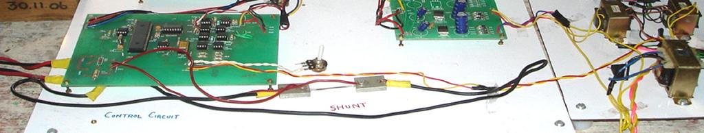
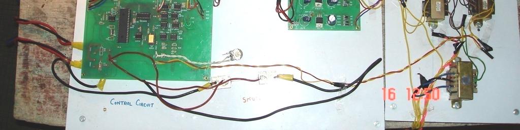
13 Control Circuit Figure 7.9 Control Circuit of the PV System
14 Sensing Panel Parameters The control circuit is shown in Figure 7.9. The panel parameters like voltage and current are sensed and transferred as an input to the microcontroller for determining the variation in power. The voltage is sensed by a voltage divider circuit and the current is sensed using shunt Voltage sensing The voltage divider circuit consists of resistances R1 and R2.The output of the voltage divider is given by the equation (7.2). V vo R2 * V ( R R ) 1 2 s (7.2) where V s = Output from solar panel in volts V vo = Voltage proportional to output voltage from solar panel in volts R 1,R 2 = Resistances in ohms The zener diode Z1 is used to limit the voltage input to the microcontroller to 5V Current sensing The dc current from the panel is sensed using a shunt which gives the output of 75 mv when a current of 10A flows. The voltage obtained from the shunt is five scaled using the operational amplifier connected in non inverting mode. The output across the zener diode is given by the equation (7.3).
15 114 V io I s 3 5 * 75*10 * ( 1) (7.3) 10 R R 4 where I s = Output current from solar panel in ampere V io = Voltage proportional to output current from solar panel in volts R 5, R 4 = Resistances in ohms Microcontroller Logic Circuit The hill climbing algorithm for the traction of maximum power point depending on variation in solar intensity is implemented using microcontroller PIC18F452. In this circuit, the reset switch is used to reset all the registers in the microcontroller whenever it is necessary. The variation in voltage and current is sensed and based on that, the modulation index value (m) is produced as an eight bit digital output in the port B of the microcontroller Digital to Analog Converter The output from the microcontroller is converted into analog form using the digital to analog converter DAC The reference signal given to the DAC is 5V.The output of the DAC is given by the equation (7.4). A1 A2 A3 A4 A5 A6 A7 A8 Modulation index 5 * (7.4) where A1 to A8 is MSB to LSB of digital modulation index
16 Modulating signal generation The modulating signal is used for the generation of inverter gate signals. In order to maintain the output of the inverter as 50Hz, the signal is tapped from the grid and stepped down to 5V. Then it is multiplied with the modulation index using analog multiplier AD532 to get the required modulating signal. The 6V signal generated from the transformer is converted into 5V using operational amplifier U1 and U2. The resultant modulating signal from the output of the multiplier is converted into two sinusoidal signals each phase shifted by 180 degree Triangular carrier signal generation The triangular wave is generated using the combination of operational amplifier operated as a square wave generator and integrator Gate Pulse Generation Circuit Figure 7.10 shows the gate pulse generating circuit. In this G1, G2, G3 and G4 represents gate pulses and R1, R2, R3 and R4 represents the respective references. The variation in the modulation index given to the PWM generation generates gate pulses to trigger the inverter and produces a constant output. The bridge inverter circuit requires four gate pulses in order to trigger the MOSFET. The first two pulses for one arm of the inverter bridge are generated by comparing the triangular and the zero phase shifted sine wave obtained from the control circuit, such that each pulse is an complement of the other. In the similar way pulses for the second arm is generated by comparing the triangular wave and 180 degree phase shifted sine wave. All the four pulses are then given to the opto-coupler MCT 2E which act as an isolator to prevent the controlling circuit from the surges arising in the inverter.
17 Figure 7.10 Gate Pulse Generation Circuit 116


18 117 Figure 7.11 shows the gate pulses generated in the gate pulse generating circuit. The pulses G1, G2, G3, G4 are obtained using oscilloscope. According to the variation in solar insolation the response of the modulation index varies. Based on the change in m value the gate pulses generated also varies its time duration. Gate pulses generated using simulation model presented in Figure 7.7 matches with the hardware gate pulse generation circuit waveforms. Figure 7.11 Gate Pulses G1, G2, G3 and G4 given to the Inverter
19 Inverter Circuit The generated gate pulses from the driver circuit are connected to the MOSFET IRF 640 which is connected in bridge configuration. The snubber circuit is connected in parallel to all the four MOSFET in order to avoid device damage due to surges. The inverter circuit is shown in the Figure Figure 7.12 Inverter Circuit

20 119 The output voltage waveform of the inverter is connected to the step up transformer to obtain a constant secondary output voltage for a load of 15W lamp. The output of the inverter is connected to the primary side of the step up transformer which is provided with tappings of 10V, 20V, 30V, 40V. According to the inverters output the corresponding tappings are used in the transformer in order to produce constant secondary voltage. Figure 7.13 shows the output voltage waveform of the inverter given to the primary of the transformer and the step up voltage output given to the load. Primary side Secondary side Figure 7.13 Voltage Waveform of Inverter with 15W Lamp Load Figures 7.14 and 7.15 shows the experimental setup for different load conditions. Depending on the solar insolation, the control circuit PC board senses and drives the gate pulse circuit which is given to the inverter circuit. The output of the inverter is given to the suitable transformer tapping in the primary side in order to produce a constant secondary output required by the load.

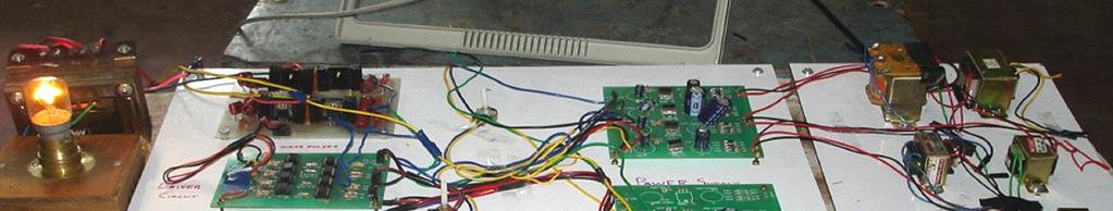

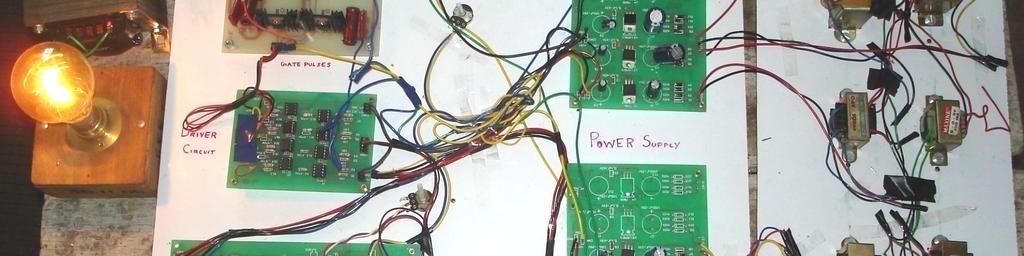
21 120 Figure 7.14 Experimental Setup with 15W Lamp Load Figure 7.15 Experimental Setup with 60W Lamp Load
22 121 Figures 7.16 and 7.17 shows the output waveform of array power versus time and array current. The graph indicates the curve drawn for two sets of datas one with MPPT control and the other without MPPT control. The graph drawn between the array power and time shows the difference in variation in the power generated with MPPT and without MPPT during the morning and evenings. By using the hill climbing algorithm, it is observed that the amount of power produced by the PV generator trained using MPPT follows the pattern of irradiance. Figure 7.16 Output waveform of Array Power Vs Time
23 122 Figure 7.17 Output Waveform of Array Power Vs Array Current 7.7 CONCLUSION The panel is trained statically using hill climbing algorithm for maximum radiation. It predicts the maximum power point voltage and the modulation index value. The pulse width modulation scheme is used to trigger the gate of the switching device, which reduces the lower order harmonics at the output of the inverter. The simulation results match with the implementation results. The implementation complexity of the system is low compared to the above two algorithms. The main advantage is, the system is not array dependent and periodic tuning is not required.
CHAPTER-3 Design Aspects of DC-DC Boost Converter in Solar PV System by MPPT Algorithm
 CHAPTER-3 Design Aspects of DC-DC Boost Converter in Solar PV System by MPPT Algorithm 44 CHAPTER-3 DESIGN ASPECTS OF DC-DC BOOST CONVERTER IN SOLAR PV SYSTEM BY MPPT ALGORITHM 3.1 Introduction In the
CHAPTER 3 APPLICATION OF THE CIRCUIT MODEL FOR PHOTOVOLTAIC ENERGY CONVERSION SYSTEM
 63 CHAPTER 3 APPLICATION OF THE CIRCUIT MODEL FOR PHOTOVOLTAIC ENERGY CONVERSION SYSTEM 3.1 INTRODUCTION The power output of the PV module varies with the irradiation and the temperature and the output
CHAPTER 3 MAXIMUM POWER TRANSFER THEOREM BASED MPPT FOR STANDALONE PV SYSTEM
 60 CHAPTER 3 MAXIMUM POWER TRANSFER THEOREM BASED MPPT FOR STANDALONE PV SYSTEM 3.1 INTRODUCTION Literature reports voluminous research to improve the PV power system efficiency through material development,
Photovoltaic Systems Engineering
 Photovoltaic Systems Engineering Ali Karimpour Assistant Professor Ferdowsi University of Mashhad Reference for this lecture: Trishan Esram and Patrick L. Chapman. Comparison of Photovoltaic Array Maximum
Maximum Power Point Tracking for Photovoltaic Systems
 Maximum Power Point Tracking for Photovoltaic Systems Ankita Barange 1, Varsha Sharma 2 1,2Dept. of Electrical and Electronics, RSR-RCET, Bhilai, C.G., India ---------------------------------------------------------------------------***---------------------------------------------------------------------------
Microcontroller Based MPPT Buck-Boost Converter
 GRD Journals- Global Research and Development Journal for Engineering Volume 1 Issue 6 May 2016 ISSN: 2455-5703 Microcontroller Based MPPT Buck-Boost Converter Anagha Mudki Assistant Professor Department
DESIGN, SIMULATION AND REAL-TIME IMPLEMENTATION OF A MAXIMUM POWER POINT TRACKER FOR PHOTOVOLTAIC SYSTEM
 IJSS : 6(1), 2012, pp. 25-29 DESIGN, SIMULATION AND REAL-TIME IMPLEMENTATION OF A MAXIMUM POWER POINT TRACKER FOR PHOTOVOLTAIC SYSTEM Md. Selim Hossain 1, Md. Selim Habib 2, Md. Abu Sayem 3 and Md. Dulal
CHAPTER 6 ANALYSIS OF THREE PHASE HYBRID SCHEME WITH VIENNA RECTIFIER USING PV ARRAY AND WIND DRIVEN INDUCTION GENERATORS
 73 CHAPTER 6 ANALYSIS OF THREE PHASE HYBRID SCHEME WITH VIENNA RECTIFIER USING PV ARRAY AND WIND DRIVEN INDUCTION GENERATORS 6.1 INTRODUCTION Hybrid distributed generators are gaining prominence over the
CHAPTER 3 MODELLING OF PV SOLAR FARM AS STATCOM
 47 CHAPTER 3 MODELLING OF PV SOLAR FARM AS STATCOM 3.1 INTRODUCTION Today, we are mostly dependent on non renewable energy that have been and will continue to be a major cause of pollution and other environmental
6. HARDWARE PROTOTYPE AND EXPERIMENTAL RESULTS
 6. HARDWARE PROTOTYPE AND EXPERIMENTAL RESULTS Laboratory based hardware prototype is developed for the z-source inverter based conversion set up in line with control system designed, simulated and discussed
MEASURING EFFICIENCY OF BUCK-BOOST CONVERTER USING WITH AND WITHOUT MODIFIED PERTURB AND OBSERVE (P&O) MPPT ALGORITHM OF PHOTO-VOLTAIC (PV) ARRAYS
 MPPT ALGORITHM OF PHOTO-VOLTAIC (PV) ARRAYS") Proceedings of the International Conference on Mechanical Engineering and Renewable Energy 2015(ICMERE2015) 26 29 November, 2015, Chittagong, Bangladesh ICMERE2015-PI-060 MEASURING EFFICIENCY OF BUCK-BOOST
Proceedings of the International Conference on Mechanical Engineering and Renewable Energy 2015(ICMERE2015) 26 29 November, 2015, Chittagong, Bangladesh ICMERE2015-PI-060 MEASURING EFFICIENCY OF BUCK-BOOST
An Interleaved High Step-Up Boost Converter With Voltage Multiplier Module for Renewable Energy System
 An Interleaved High Step-Up Boost Converter With Voltage Multiplier Module for Renewable Energy System Vahida Humayoun 1, Divya Subramanian 2 1 P.G. Student, Department of Electrical and Electronics Engineering,
Design of Single-Stage Transformer less Grid Connected Photovoltaic System
 Design of Single-Stage Transformer less Grid Connected Photovoltaic System Prabhakar Kumar Pranav Department of Electrical Engineering, G. H. Raisoni Institute of Engineering & Technology, Wagholi, Pune,
Chapter-4. Fixed and Variable Step-Size Perturb Voltage MPPT Control for Photovoltaic System
 58 Chapter-4 Fixed and Variable Step-Size Perturb Voltage MPPT Control for Photovoltaic System 4.1 Introduction Owing to the global development toward the design and analysis development of PV systems
Photovoltaic Battery Charging System Based on PIC16F877A Microcontroller
 Photovoltaic Battery Charging System Based on PIC16F877A Microcontroller Zaki Majeed Abdu-Allah, Omar Talal Mahmood, Ahmed M. T. Ibraheem AL-Naib Abstract This paper presents the design and practical implementation
CHAPTER 5 MPPT OF PV MODULE BY CONVENTIONAL METHODS
 85 CHAPTER 5 MPPT OF PV MODULE BY CONVENTIONAL METHODS 5.1 PERTURB AND OBSERVE METHOD It is well known that the output voltage and current and also the output power of PV panels vary with atmospheric conditions
An Interleaved High-Power Fly back Inverter for Photovoltaic Applications
 An Interleaved High-Power Fly back Inverter for Photovoltaic Applications S.Sudha Merlin PG Scholar, Department of EEE, St.Joseph's College of Engineering, Semmencherry, Chennai, Tamil Nadu, India. ABSTRACT:
Hardware Implementation of Maximum Power Point Tracking System using Cuk and Boost Converters
 Hardware Implementation of Maximum Power Point Tracking System using Cuk and Boost Converters Gomathi B 1 Assistant Professor, Electrical and Electronics Engineering, PSNA College of Engineering and Technology,
A Current Sensor-less Maximum Power Point Tracking Method for PV
 A Current Sensor-less Maximum Power Point Tracking Method for PV System 1 Byunggyu Yu, 2 Ahmed G. Abo-Khalil 1, First Author, Corresponding Author Kongju National University, bgyuyu@kongju.ac.kr 2 Majmaah
Comparative study of maximum power point tracking methods for photovoltaic system
 Comparative study of maximum power point tracking methods for photovoltaic system M.R.Zekry 1, M.M.Sayed and Hosam K.M. Youssef Electric Power and Machines Department, Faculty of Engineering, Cairo University,
Finite Step Model Predictive Control Based Asymmetrical Source Inverter with MPPT Technique
 International Journal of Engineering Research and Development e-issn: 2278-067X, p-issn: 2278-800X, www.ijerd.com Volume 11, Issue 01 (January 2015), PP.08-16 Finite Step Model Predictive Control Based
PV Charger System Using A Synchronous Buck Converter
 PV Charger System Using A Synchronous Buck Converter Adriana FLORESCU Politehnica University of Bucharest,Spl. IndependenŃei 313 Bd., 060042, Bucharest, Romania, adriana.florescu@yahoo.com Sergiu OPREA
Chapter 3 : Closed Loop Current Mode DC\DC Boost Converter
 Chapter 3 : Closed Loop Current Mode DC\DC Boost Converter 3.1 Introduction DC/DC Converter efficiently converts unregulated DC voltage to a regulated DC voltage with better efficiency and high power density.
DESIGN AND SIMULATION OF IMPROVED DC- DC CONVERTERS USING SIMULINK FOR GRID CONNECTED PV SYSTEMS
 International Journal of Electronics and Communication Engineering and Technology (IJECET) Volume 8, Issue 6, November-December 2017, pp. 62 71, Article ID: IJECET_08_06_006 Available online at http://www.iaeme.com/ijecet/issues.asp?jtype=ijecet&vtype=8&itype=6
A NEW APPROACH OF MODELLING, SIMULATION OF MPPT FOR PHOTOVOLTAIC SYSTEM IN SIMULINK MODEL
 A NEW APPROACH OF MODELLING, SIMULATION OF MPPT FOR PHOTOVOLTAIC SYSTEM IN SIMULINK MODEL M. Abdulkadir, A. S. Samosir, A. H. M. Yatim and S. T. Yusuf Department of Energy Conversion, Faculty of Electrical
CHAPTER 5 CONTROL SYSTEM DESIGN FOR UPFC
 90 CHAPTER 5 CONTROL SYSTEM DESIGN FOR UPFC 5.1 INTRODUCTION This chapter deals with the performance comparison between a closed loop and open loop UPFC system on the aspects of power quality. The UPFC
CHAPTER 3 CUK CONVERTER BASED MPPT SYSTEM USING ADAPTIVE PAO ALGORITHM
 52 CHAPTER 3 CUK CONVERTER BASED MPPT SYSTEM USING ADAPTIVE PAO ALGORITHM 3.1 INTRODUCTION The power electronics interface, connected between a solar panel and a load or battery bus, is a pulse width modulated
CHAPTER 3 SINGLE SOURCE MULTILEVEL INVERTER
 42 CHAPTER 3 SINGLE SOURCE MULTILEVEL INVERTER 3.1 INTRODUCTION The concept of multilevel inverter control has opened a new avenue that induction motors can be controlled to achieve dynamic performance
CHAPTER 2 LITERATURE SURVEY
 13 CHAPTER 2 LITERATURE SURVEY 2.1 INTRODUCTION Investment in solar photovoltaic (PV) energy is rapidly increasing worldwide due to its long term economic prospects and more crucially, concerns over the
Power Quality Improvement in Hybrid Power Generation for Distribution System Using PWM Technique
 Power Quality Improvement in Hybrid Power Generation for Distribution System Using PWM Technique T.Vikram 1, P.Santhosh Kumar 2, Sangeet.R.Nath 3, R.Sampathkumar 4 B. E. Scholar, Dept. of EEE, ACET, Tirupur,
Design and Analysis of ANFIS Controller to Control Modulation Index of VSI Connected to PV Array
 Available online www.ejaet.com European Journal of Advances in Engineering and Technology, 2015, 2(5): 12-17 Research Article ISSN: 2394-658X Design and Analysis of ANFIS Controller to Control Modulation
Comparative Study of P&O and InC MPPT Algorithms
 American Journal of Engineering Research (AJER) e-issn : 2320-0847 p-issn : 2320-0936 Volume-02, Issue-12, pp-402-408 www.ajer.org Research Paper Open Access Comparative Study of P&O and InC MPPT Algorithms
The table below gives some summary facts to the two set of data and show that they correlate to a high degree of the course of a year.
 System Simulations Following the PDR presentation, it became obvious we needed away to better assess our design decisions and test whether they were feasible. In the following system simulations the key
Multilevel Inverter for Grid-Connected PV SystemEmploying MPPT and PI Controller
 Multilevel Inverter for Grid-Connected PV SystemEmploying MPPT and PI Controller Seena M Varghese P. G. Student, Department of Electrical and Electronics Engineering, Saintgits College of Engineering,
A Hybrid Particle Swarm Optimization Algorithm for Maximum Power Point Tracking of Solar Photovoltaic Systems
 Proceedings of The National Conference On Undergraduate Research (NCUR) 2017 University of Memphis Memphis, Tennessee April 6-8, 2017 A Hybrid Particle Swarm Optimization Algorithm for Maximum Power Point
A Single Stage CCM Zeta Micro inverter for Solar Photovoltaic AC Module. Abstract
 Page number 1 A Single Stage CCM Zeta Micro inverter for Solar Photovoltaic AC Module Introduction: Abstract Among various microinverters reported in literature, the most generic are two stage inverters
CHAPTER 4 MULTI-LEVEL INVERTER BASED DVR SYSTEM
 64 CHAPTER 4 MULTI-LEVEL INVERTER BASED DVR SYSTEM 4.1 INTRODUCTION Power electronic devices contribute an important part of harmonics in all kind of applications, such as power rectifiers, thyristor converters
DESIGN AND IMPLEMENTATION OF SOLAR POWERED WATER PUMPING SYSTEM
 DESIGN AND IMPLEMENTATION OF SOLAR POWERED WATER PUMPING SYSTEM P. Nisha, St.Joseph s College of Engineering, Ch-119 nishasjce@gmail.com,ph:9940275070 Ramani Kalpathi, Professor, St.Joseph s College of
Design and Implementation of Photovoltaic Inverter system using Multi-cell Interleaved Fly-back Topology
 International Journal of ChemTech Research CODEN (USA): IJCRGG, ISSN: 0974-4290, ISSN(Online):2455-9555 Vol.10 No.14, pp 300-308, 2017 Design and Implementation of Photovoltaic Inverter system using Multi-cell
Modeling of PV Array and Performance Enhancement by MPPT Algorithm
 Modeling of PV Array and Performance Enhancement by MPPT Algorithm R.Sridhar Asst.Professor, EEE Department SRM University, Chennai, India. Dr.Jeevananathan Asst.Professor, EEE Department Pondichery University,
CHAPTER 4 CONTROL ALGORITHM FOR PROPOSED H-BRIDGE MULTILEVEL INVERTER
 65 CHAPTER 4 CONTROL ALGORITHM FOR PROPOSED H-BRIDGE MULTILEVEL INVERTER 4.1 INTRODUCTION Many control strategies are available for the control of IMs. The Direct Torque Control (DTC) is one of the most
CHAPTER 5 MODIFIED SINUSOIDAL PULSE WIDTH MODULATION (SPWM) TECHNIQUE BASED CONTROLLER
 TECHNIQUE BASED CONTROLLER") 74 CHAPTER 5 MODIFIED SINUSOIDAL PULSE WIDTH MODULATION (SPWM) TECHNIQUE BASED CONTROLLER 5.1 INTRODUCTION Pulse Width Modulation method is a fixed dc input voltage is given to the inverters and a controlled
74 CHAPTER 5 MODIFIED SINUSOIDAL PULSE WIDTH MODULATION (SPWM) TECHNIQUE BASED CONTROLLER 5.1 INTRODUCTION Pulse Width Modulation method is a fixed dc input voltage is given to the inverters and a controlled
Modelling of Single Stage Inverter for PV System Using Optimization Algorithm
 TELKOMNIKA Indonesian Journal of Electrical Engineering Vol. 12, No. 9, September 2014, pp. 6579 ~ 6586 DOI: 10.11591/telkomnika.v12i9.6466 6579 Modelling of Single Stage Inverter for PV System Using Optimization
Grid Connected photovoltaic system based on Chain cell converter Using Simulink
 Grid Connected photovoltaic system based on Chain cell converter Using Simulink Problem statement To prove Chain cell converter performance superior when compared with the traditional Pulse width modulation
Analysis of Solar PV Inverter based on PIC Microcontroller and Sinusoidal Pulse Width Modulation
 IJSRD - International Journal for Scientific Research & Development Vol. 4, Issue 08, 2016 ISSN (online): 2321-0613 Analysis of Solar PV Inverter based on PIC Microcontroller and Sinusoidal Pulse Width
Implementation of Buck-Boost Converter with Coupled Inductor for Photo-Voltaic System
 Bulletin of Electrical Engineering and Informatics Vol. 3, No. 4, December 2014, pp. 259~264 ISSN: 2089-3191 259 Implementation of Buck-Boost Converter with Coupled Inductor for Photo-Voltaic System M.S.
Photovoltaic Systems I EE 446/646
 Photovoltaic Systems I EE 446/646 PV System Types & Goal Types of PV Systems: Grid-tied systems that feed power directly into the utility grid, Residential Systems (1-10kW) Commercial/industrial systems
IMPLEMENTATION OF BUCK BOOST CONVERTER WITH COUPLED INDUCTOR FOR PHOTO-VOLTAIC SYSTEM
 IMPLEMENTATION OF BUCK BOOST CONVERTER WITH COUPLED INDUCTOR FOR PHOTO-VOLTAIC SYSTEM *M.S.Subbulakshmi, **D.Vanitha *M.E(PED) Student,Department of EEE, SCSVMV University,Kanchipuram, India 07sujai@gmail.com
Proposed System Model and Simulation for Three Phase Induction Motor Operation with Single PV Panel
 Proposed System Model and Simulation for Three Phase Induction Motor Operation with Single PV Panel Eliud Ortiz-Perez, Ricardo Maldonado, Harry O Neill, Eduardo I. Ortiz-Rivera (IEEE member) University
CHAPTER IV DESIGN AND ANALYSIS OF VARIOUS PWM TECHNIQUES FOR BUCK BOOST CONVERTER
 59 CHAPTER IV DESIGN AND ANALYSIS OF VARIOUS PWM TECHNIQUES FOR BUCK BOOST CONVERTER 4.1 Conventional Method A buck-boost converter circuit is a combination of the buck converter topology and a boost converter
ELG4139: DC to AC Converters
 ELG4139: DC to AC Converters Converts DC to AC power by switching the DC input voltage (or current) in a pre-determined sequence so as to generate AC voltage (or current) output. I DC I ac + + V DC V ac
OPTIMAL DIGITAL CONTROL APPROACH FOR MPPT IN PV SYSTEM
 Int. J. Engg. Res. & Sci. & Tech. 2015 N Ashok Kumar et al., 2015 Research Paper ISSN 2319-5991 www.ijerst.com Vol. 4, No. 4, November 2015 2015 IJERST. All Rights Reserved OPTIMAL DIGITAL CONTROL APPROACH
Simulation of Standalone PV System Using P&O MPPT Technique in Matlab/Simulink
 International Journal of Engineering Research and Development (IJERD) ISSN: 2278-067X (Page 72-77) Simulation of Standalone PV System Using P&O MPPT Technique in Matlab/Simulink Keyurkumar Patel 1, Kedar
PV PANEL WITH CIDBI (COUPLED INDUCTANCE DOUBLE BOOST TOPOLOGY) DC-AC INVERTER
 DC-AC INVERTER") PV PANEL WITH CIDBI (COUPLED INDUCTANCE DOUBLE BOOST TOPOLOGY) DC-AC INVERTER Mr.Thivyamoorthy.S 1,Mrs.Bharanigha 2 Abstract--In this paper the design and the control of an individual PV panel dc-ac converter
PV PANEL WITH CIDBI (COUPLED INDUCTANCE DOUBLE BOOST TOPOLOGY) DC-AC INVERTER Mr.Thivyamoorthy.S 1,Mrs.Bharanigha 2 Abstract--In this paper the design and the control of an individual PV panel dc-ac converter
Parallel or Standalone Operation of Photovoltaic Cell with MPPT to DC Load
 Parallel or Standalone Operation of Photovoltaic Cell with MPPT to DC Load Subhashanthi.K 1, Amudhavalli.D 2 PG Scholar [Power Electronics & Drives], Dept. of EEE, Sri Venkateshwara College of Engineering,
Micro-controller Based Three-phase Voltage Source Inverter for Alternative Energy Source. Abstract
 Micro-controller Based Three-phase Voltage Source Inverter for Alternative Energy Source M.M. A. Rahman, Kurt Hammons, Phillip Beemer, Marcia Isserstedt, and Matt Trommater School of Engineering Padnos
Design of Single Phase Pure Sine Wave Inverter for Photovoltaic Application
 Design of Single Phase Pure Sine Wave Inverter for Photovoltaic Application Yash Kikani School of Technology, Pandit Deendayal Petroleum University, India yashkikani004@gmail.com Abstract:- This paper
MPPT based New Transformer Less PV Inverter Topology with Low Leakage Current
 IJIRST International Journal for Innovative Research in Science & Technology Volume 1 Issue 12 May 215 ISSN (online): 2349-61 MPPT based New Transformer Less PV Archu S Vijay PG Student Department of Electrical
Low Cost MPPT Algorithms for PV Application: PV Pumping Case Study. M. A. Elgendy, B. Zahawi and D. J. Atkinson. Presented by:
 Low Cost MPPT Algorithms for PV Application: PV Pumping Case Study M. A. Elgendy, B. Zahawi and D. J. Atkinson Presented by: Bashar Zahawi E-mail: bashar.zahawi@ncl.ac.uk Outline Maximum power point tracking
DESIGN OF CUK CONVERTER WITH MPPT TECHNIQUE
 Vol. 1, Issue 4, July 2013 DESIGN OF CUK CONVERTER WITH MPPT TECHNIQUE Srushti R.Chafle 1, Uttam B. Vaidya 2, Z.J.Khan 3 M-Tech Student, RCERT, Chandrapur, India 1 Professor, Dept of Electrical & Power,
MODELING AND SIMULATION OF PHOTOVOLTAIC SYSTEM EMPLOYING PERTURB AND OBSERVE MPPT ALGORITHM AND FUZZY LOGIC CONTROL
 MODELING AND SIMULATION OF PHOTOVOLTAIC SYSTEM EMPLOYING PERTURB AND OBSERVE MPPT ALGORITHM AND FUZZY LOGIC CONTROL 1 ANAS EL FILALI, 2 EL MEHDI LAADISSI and 3 MALIKA ZAZI 1,2,3 Laboratory LM2PI, ENSET,
CHAPTER-5 DESIGN OF DIRECT TORQUE CONTROLLED INDUCTION MOTOR DRIVE
 113 CHAPTER-5 DESIGN OF DIRECT TORQUE CONTROLLED INDUCTION MOTOR DRIVE 5.1 INTRODUCTION This chapter describes hardware design and implementation of direct torque controlled induction motor drive with
Design And Analysis Of Dc-Dc Converter For Photovoltaic (PV) Applications.
 Applications.") IOSR Journal of Engineering (IOSRJEN) ISSN (e): 2250-3021, ISSN (p): 2278-8719 PP 53-60 www.iosrjen.org Design And Analysis Of Dc-Dc Converter For Photovoltaic (PV) Applications. Sangeetha U G 1 (PG Scholar,
IOSR Journal of Engineering (IOSRJEN) ISSN (e): 2250-3021, ISSN (p): 2278-8719 PP 53-60 www.iosrjen.org Design And Analysis Of Dc-Dc Converter For Photovoltaic (PV) Applications. Sangeetha U G 1 (PG Scholar,
HYBRID SOLAR SYSTEM USING MPPT ALGORITHM FOR SMART DC HOUSE
 Volume 118 No. 10 2018, 409-417 ISSN: 1311-8080 (printed version); ISSN: 1314-3395 (on-line version) url: http://www.ijpam.eu doi: 10.12732/ijpam.v118i10.81 ijpam.eu HYBRID SOLAR SYSTEM USING MPPT ALGORITHM
Chapter-5. Adaptive Fixed Duty Cycle (AFDC) MPPT Algorithm for Photovoltaic System
 MPPT Algorithm for Photovoltaic System") 88 Chapter-5 Adaptive Fixed Duty Cycle (AFDC) MPPT Algorithm for Photovoltaic System 5.1 Introduction Optimum power point tracker (OPPT), despite its drawback of low efficiency, is a technique to achieve
88 Chapter-5 Adaptive Fixed Duty Cycle (AFDC) MPPT Algorithm for Photovoltaic System 5.1 Introduction Optimum power point tracker (OPPT), despite its drawback of low efficiency, is a technique to achieve
Micro Controller Based Ac Power Controller
 Wireless Sensor Network, 9, 2, 61-121 doi:1.4236/wsn.9.112 Published Online July 9 (http://www.scirp.org/journal/wsn/). Micro Controller Based Ac Power Controller S. A. HARI PRASAD 1, B. S. KARIYAPPA 1,
CHAPTER 4 DESIGN OF CUK CONVERTER-BASED MPPT SYSTEM WITH VARIOUS CONTROL METHODS
 68 CHAPTER 4 DESIGN OF CUK CONVERTER-BASED MPPT SYSTEM WITH VARIOUS CONTROL METHODS 4.1 INTRODUCTION The main objective of this research work is to implement and compare four control methods, i.e., PWM
Comparison Of DC-DC Boost Converters Using SIMULINK
 IOSR Journal of Electrical and Electronics Engineering (IOSR-JEEE) e-issn: 2278-1676,p-ISSN: 2320-3331, PP 34-42 www.iosrjournals.org Comparison Of DC-DC Boost Converters Using SIMULINK Anupa Ann Alex
Implementation of P&O MPPT for PV System with using Buck and Buck-Boost Converters
 ISSN: 2349-2503 Implementation of P&O MPPT for PV System with using Buck and Buck-Boost Converters V R Bharambe 1 Prof K M Mahajan 2 1 (PG Student, Elect Engg Dept, K,C.E.C.O.E.&I.T, Jalgaon, India, vaishalibharambe5@gmail.com)
Sepic Topology Based High Step-Up Step down Soft Switching Bidirectional DC-DC Converter for Energy Storage Applications
 IOSR Journal of Electrical and Electronics Engineering (IOSR-JEEE) e-issn: 2278-1676,p-ISSN: 2320-3331, Volume 12, Issue 3 Ver. IV (May June 2017), PP 68-76 www.iosrjournals.org Sepic Topology Based High
A Variable Step Size MPPT Method for Stand-Alone PV Energy Systems
 Journal of Energy and Natural Resources 2016; 5(1-1): 1-5 Published online January 12, 2016 (http://www.sciencepublishinggroup.com/j/jenr) doi: 10.11648/j.jenr.s.2016050101.11 ISSN: 2330-7366 (Print);
IMPLEMENTATION OF QALU BASED SPWM CONTROLLER THROUGH FPGA. This Chapter presents an implementation of area efficient SPWM
 3 Chapter 3 IMPLEMENTATION OF QALU BASED SPWM CONTROLLER THROUGH FPGA 3.1. Introduction This Chapter presents an implementation of area efficient SPWM control through single FPGA using Q-Format. The SPWM
Design and Simulation of a Solar Regulator Based on DC-DC Converters Using a Robust Sliding Mode Controller
 Journal of Energy and Power Engineering 9 (2015) 805-812 doi: 10.17265/1934-8975/2015.09.007 D DAVID PUBLISHING Design and Simulation of a Solar Regulator Based on DC-DC Converters Using a Robust Sliding
Application of Model Predictive Control in PV-STATCOM for Achieving Faster Response
 Application of Model Predictive Control in PV-STATCOM for Achieving Faster Response Sanooja Jaleel 1, Dr. K.N Pavithran 2 1Student, Department of Electrical and Electronics Engineering, Government Engineering
MPPT with Z Impedance Booster
 International Journal of Electrical Engineering. ISSN 0974-2158 Volume 7, Number 3 (2014), pp. 475-483 International Research Publication House http://www.irphouse.com MPPT with Z Impedance Booster Govind
ABSTRACT AN IMPROVED MAXIMUM POWER POINT TRACKING ALGORITHM USING FUZZY LOGIC CONTROLLER FOR PHOTOVOLTAIC APPLICATIONS
 ABSTRACT AN IMPROVED MAXIMUM POWER POINT TRACKING ALGORITHM USING FUZZY LOGIC CONTROLLER FOR PHOTOVOLTAIC APPLICATIONS This thesis proposes an advanced maximum power point tracking (MPPT) algorithm using
An Interleaved Flyback Inverter for Residential Photovoltaic Applications
 An Interleaved Flyback Inverter for Residential Photovoltaic Applications Bunyamin Tamyurek and Bilgehan Kirimer ESKISEHIR OSMANGAZI UNIVERSITY Electrical and Electronics Engineering Department Eskisehir,
Modular Grid Connected Photovoltaic System with New Multilevel Inverter
 Modular Grid Connected Photovoltaic System with New Multilevel Inverter Arya Sasi 1, Jasmy Paul 2 M.Tech Scholar, Dept. of EEE, ASIET, Kalady, Mahatma Gandhi University, Kottayam, Kerala, India 1 Assistant
CHAPTER 6 INPUT VOLATGE REGULATION AND EXPERIMENTAL INVESTIGATION OF NON-LINEAR DYNAMICS IN PV SYSTEM
 CHAPTER 6 INPUT VOLATGE REGULATION AND EXPERIMENTAL INVESTIGATION OF NON-LINEAR DYNAMICS IN PV SYSTEM 6. INTRODUCTION The DC-DC Cuk converter is used as an interface between the PV array and the load,
ISSN Vol.07,Issue.01, January-2015, Pages:
 ISSN 2348 2370 Vol.07,Issue.01, January-2015, Pages:0065-0072 www.ijatir.org A Novel Improved Variable Step Size of Digital MPPT Controller For A Single Sensor in Photo Voltaic System K.MURALIDHAR REDDY
DESIGN & SIMULATION OF LOW POWER HOME UTILITY GRID CONNECTED PV SYSTEM USING P&O METHOD
 DESIGN & SIMULATION OF LOW POWER HOME UTILITY GRID CONNECTED PV SYSTEM USING P&O METHOD 1 Yogita Sahu, 2 Amit Chouksey 1 Research Scholar, 2 Professor M.Tech., Digital Communication, Gyan Ganga College
A Variable Step Size Perturb and Observe Algorithm for Photovoltaic Maximum Power Point Tracking
 A Variable Step Size Perturb and Observe Algorithm for Photovoltaic Maximum Power Point Tracking F. A. O. Aashoor University of Bath, UK F.A.O.Aashoor@bath.ac.uk Abstract Photovoltaic (PV) panels are devices
A Three Phase Power Conversion Based on Single Phase and PV System Using Cockcraft-Walton Voltage
 Journal of Advanced Engineering Research ISSN: 2393-8447 Volume 2, Issue 2, 2015, pp.46-50 A Three Phase Power Conversion Based on Single Phase and PV System Using Cockcraft-Walton Voltage R. Balaji, V.
Levels of Inverter by Using Solar Array Generation System
 Levels of Inverter by Using Solar Array Generation System Ganesh Ashok Ubale M.Tech (Digital Systems) E&TC, Government College of Engineering, Jalgaon, Maharashtra. Prof. S.O.Dahad, M.Tech HOD, (E&TC Department),
Maximum Power Point Tracking Using Perturb & Observe Method For Photovoltaic System Based On Microcontroller
 Maximum Power Point Tracking Using Perturb & Observe Method For Photovoltaic System Based On Microcontroller Ratna Ika Putri, M. Rifa i, Sidik Nurcahyo Electronic Engineering Department State Polytechnic
An Efficient DC-DC converter with Analog MPPT controller for the stand alone Photo Voltaic system
 Research Article International Journal of Current Engineering and Technology ISSN 2277-4106 2013 INPRESSCO. All Rights Reserved. Available at http://inpressco.com/category/ijcet An Efficient DC-DC converter
CHAPTER 4 FUZZY LOGIC BASED PHOTO VOLTAIC ENERGY SYSTEM USING SEPIC
 56 CHAPTER 4 FUZZY LOGIC BASED PHOTO VOLTAIC ENERGY SYSTEM USING SEPIC 4.1 INTRODUCTION A photovoltaic system is a one type of solar energy system which is designed to supply electricity by using of Photo
Development of a Fuzzy Logic based Photovoltaic Maximum Power Point Tracking Control System using Boost Converter
 Development of a Fuzzy Logic based Photovoltaic Maximum Power Point Tracking Control System using Boost Converter Triveni K. T. 1, Mala 2, Shambhavi Umesh 3, Vidya M. S. 4, H. N. Suresh 5 1,2,3,4,5 Department
Enhanced MPPT Technique For DC-DC Luo Converter Using Model Predictive Control For Photovoltaic Systems
 International Journal of Engineering Research and Development e-issn: 2278-067X, p-issn: 2278-800X, www.ijerd.com Volume 11, Issue 01 (January 2015), PP.18-27 Enhanced MPPT Technique For DC-DC Luo Converter
Design and Implementation of Single-Stage Grid-Connected Flyback Microinverter Operates in DCM for Photovoltaic Applications
 Design and Implementation of Single-Stage Grid-Connected Flyback Microinverter Operates in DCM for Photovoltaic Applications Turki K. Hassan 1 and Mustafa A. Fadel 2 1 PhD, Electrical Engineering Department,
Simulation based study of Maximum Power Point Tracking and Frequency Regulation for Stand-alone Solar Photovoltaic Systems
 International Conference on Renewable Energies and Power Quality (ICREPQ 14) Cordoba (Spain), 8 th to 10 th April, 2014 Renewable Energy and Power Quality Journal (RE&PQJ) ISSN 2172-038 X, No.12, April
Keywords: Photovoltaic, Fuzzy, Maximum Power Point tracking, Boost converter, Capacitor.
 International Journal of Engineering Research and Development e-issn: 2278-067X, p-issn: 2278-800X, www.ijerd.com Volume 10, Issue 12 (December 2014), PP.58-64 Development and Analysis of Fuzzy Control
Simulation of Perturb and Observe MPPT algorithm for FPGA
 Simulation of Perturb and Observe MPPT algorithm for FPGA Vinod Kumar M. P. 1 PG Scholar, Department of Electrical and Electronics Engineering, NMAMIT, Nitte, Udupi, India 1 ABSTRACT: The generation of
Shunt Active Power Filter connected to MPPT based photo voltaic Array for PQ enhancement
 Volume 114 No. 9 217, 389-398 ISSN: 1311-88 (printed version); ISSN: 1314-3395 (on-line version) url: http://www.ijpam.eu ijpam.eu Shunt Active Power Filter connected to MPPT based photo voltaic Array
Maximum Power Point Tracking Performance Evaluation of PV micro-inverter under Static and Dynamic Conditions
 International Journal of Engineering Research and Technology. ISSN 0974-3154 Volume 11, Number 5 (2018), pp. 763-770 International Research Publication House http://www.irphouse.com Maximum Power Point
MAXIMUM POWER POINT TRACKING OF PV ARRAYS UNDER PARTIAL SHADING CONDITION USING SEPIC CONVERTER
 MAXIMUM POWER POINT TRACKING OF PV ARRAYS UNDER PARTIAL SHADING CONDITION USING SEPIC CONVERTER Sreekumar 1 A V, Arun Rajendren 2 1 M.Tech Student, Department of EEE, Amrita School of Engineering, Kerala,
A Novel Grid Connected PV Micro Inverter
 IOSR Journal of Electrical and Electronics Engineering (IOSR-JEEE) e-issn: 2278-1676,p-ISSN: 2320-3331 PP 66-71 www.iosrjournals.org A Novel Grid Connected PV Micro Inverter Jijo Balakrishnan 1, Kannan
A Three-Phase Grid-Connected Inverter for Photovoltaic Applications Using Fuzzy MPPT
 A Three-Phase Grid-Connected Inverter for Photovoltaic Applications Using Fuzzy MPPT Jaime Alonso-Martínez, Santiago Arnaltes Dpt. of Electrical Engineering, Univ. Carlos III de Madrid Avda. Universidad
CHAPTER 5 NOVEL CARRIER FUNCTION FOR FUNDAMENTAL FORTIFICATION IN VSI
 98 CHAPTER 5 NOVEL CARRIER FUNCTION FOR FUNDAMENTAL FORTIFICATION IN VSI 5.1 INTRODUCTION This chapter deals with the design and development of FPGA based PWM generation with the focus on to improve the
Voltage-MPPT Controller Design of Photovolatic Array System Using Fuzzy Logic Controller
 Advances in Energy and Power 2(1): 1-6, 2014 DOI: 10.13189/aep.2014.020101 http://www.hrpub.org Voltage-MPPT Controller Design of Photovolatic Array System Using Fuzzy Logic Controller Faridoon Shabaninia