Techniques in solar polarimetry / magnetography. Achim Gandorfer MPS
|
|
|
- Sibyl Daniel
- 6 years ago
- Views:
Transcription
1 Techniques in solar polarimetry / magnetography Achim Gandorfer MPS
2 Contents What is polarimetry? Why polarimetry? sources of polarization in astrophysics description of polarized light observing principles polarimetric techniques modulation schemes and modulators demodulation techniques extending the wavelength range
3 What is polarimetry? polarimetry is the art of quantitatively determine the degree of polarization of light. spectropolarimetry is the even higher art of measuring the degree of polarisation as a function of wavelength
4 Why polarimetry polarization yields information that cannot be obtained via classical photometry, spectroscopy polarization information is add-on to pure intensity measurements, not in competition not looking for polarization is wasting information! Photons are expensive, make use of them!
5 polarised light is a signature of the transverse wave character of light is a signature of broken symmetry in a system (something has a prefered direction/orientation; in other words: without a reason, light won t be polarised!
6 Sources of (astrophysical) polarization light can be polarized only by processes, in which light interacts with matter and if as seen from the observer the rotational symmetry of the interaction process is broken.
 Zeeman effect (magnetic")
7 effects that create polarization reflection total reflection refraction scattering dichroism (synchrotron radiation) Zeeman effect (magnetic fields!)
8 polarised light in optical solar physics In solar research polarimetry is to 99% related to the investigation of Zeeman effect induced polarisation quantitative investigation of solar magnetic fields.
9 Zeeman effect describes the shift of atomic energy levels in the presence of a magnetic field. This shift removes the degeneracy of the m-state levels and leads to a splitting of the related spectral lines. Thecomponents of the line are now polarised, depending on the geometry of the situation (magnetic field direction AND observing direction).

10 Zeeman effect
11 effects that alter polarization reflection refraction birefringence Faraday effect (magnetic fields) Hanle effect (magnetic fields)
12 Hanle effect Hanle effect: Modification of scattering polarisation (of spectral lines) in the presence of a magnetic field
13 characteristics of solar Zeeman polarisation magnetically induced splitting typically comparable to Doppler width of spectral lines needs very high spectral resolution to be resolved!! leads to tiny polarisation degrees (since only small part of the resolution element is filled with magnetic field)
14 optical magnetometer Magnetometer = Wavelength selector spectrograph + Polarimeter spectropolarimeter monochromatic filter (filter) magnetograph

15 Example: picture of an active region in intensity and polarisation IntensityI image (what you would see with your eye or a CCD) same scene, now the U degree of the other linear polarisation is shown same scene, now Q the degree of linear polarisation is shown same scene, V now the degree of circular polarisation is shown

16 Example: detail of solar spectrum in intensity and polarisation Intensity image (what you would see with your eye or a CCD) same spectrum, now the degree of linear polarisation is shown same spectrum, now the degree of the other linear polarisation is shown same spectrum, now the degree of circular polarisation is shown
17 Nota bene! in this lecture we will deal with the quantitative measurement of the polarization only, not of the magnetic field!! no convertion from polarization maps magnetic field maps ( inversion techniques ) no interpretation of measured polarisation
18 Description of polarized light light represented as electromagnetic tranverse wave polarization is a characterisation of the vibration plane of the electric field vector

19 2component vector containing complex E x, E y fields very convenient for description of elementary interaction processes only useful for idealised light: monochromatic! Jones formalism
20 Stokes formalism Jones representation not adequate for real light: partially polarized light with non zero frequency bandwidth better for daily life: representation in terms of intensity, not amplitude time average over many periods (visible light: Hz!!!) allows description of white light, partially polarized, incoherent, undirected... Stokes representation (1852)
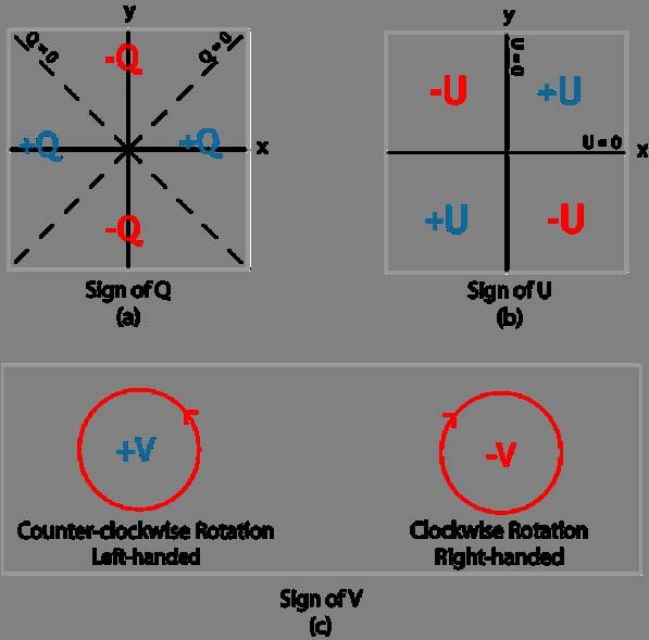
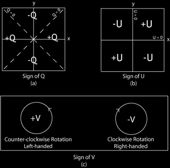
21 Stokes vector in the Stokes formulation light is represented by a four component vector I: I represents the ordinary scalar intensity, Q,U,V are differences of intensities measured by placing 6 ideal filters between source and intensity detector
22 practical meaning of the Stokes components I, Q, U, V are measurable quantities each parameter represents the difference between TWO dedicated measurements:


23 the six idealised filters for the Stokes description
24
25 advantages of the Stokes representation perfectly represents measurement procedure not restricted to monochromatic light can describe unpolarized light (classical radiative transfer equation can be formally expanded to vector equation by replacing scalar I with vector I) optical components altering polarisation can be very conveniently described by matrices ( Mueller matrices ) acting on the Stokes vector
26 some facts about Mueller matrices an optical component acts on a Stokes vector M is a 4x4 matrix a complex optical train can be represented by the matrix product of its individual component matrices
27 some important Mueller matrices partial linear polarizer (0 o ) a total linear polarizer transmits only Stokes Q and makes U and V to zero! retardation plate (phase retarder, retardance Φ, birefringent element) mixes U and V! always:
28 basic rules for Mueller matrices Mueller matrices can be multiplied attention: don t exchange components along the path!!!!! optical component M rotated by angle α : with rotation matrix
29 Polarimetric basics polarimetry = differential photometry polarisation images are linear combinations of photometric or spectral intensity images, which have been taken in different polarisation states
30 Q,U,V, and I: The polarisation Q,U,V mostly << I degree polarization degree Q/I (U/I,V/I) small (typically 10-4 <Q/I<10-2 ) detect small intensity difference on top of large intensity
31 Example: detection of Stokes Q: two measurements: linear polarizer 0 o, 90 o I 1 =0.5(I+Q) I 2 =0.5(I-Q) Q/I=(I 1 -I 2 )/(I 1 +I 2 ) normalized Stokes parameter : very accurate, since efficiency of detector divides out : differential measurement I I/2 Q
32 Two basic techniques sequential detection with one detector (single beam polarimetry): Use of a modulator/polarizer combination to convert the polarisation information into a time-dependent intensity temporal modulation simultaneous detection with two different detectors (dual beam polarimetry): Use a polarising beam splitter to spatially separate both orthogonal polarisation states at the same time spatial modulation
33 We repeat Since the eye or a CCD are not itself sensitive to polarisation, we convert the polarisation information into an intensity-difference, which we meausure. Sounds easy, let s do it.
34 Systematic error sources 1. seeing: I intensity changes during measurement : intensity difference has nothing to do with polarization t
35 Systematic error sources 1. seeing 2. gain-table or flat field : detector sensitivity varies from 1 exposure to the other signal difference has nothing to do with polarisation
36 Systematic error sources 1. seeing 2. gain-table or flat field 3. photon noise: statistical character of photons σ~ N, N number of photons noise increases with number of photons, but Signal-to-noise decreases!
37 How to do sensitive polarimetry? seeing noise gain table noise photon noise fast polarization modulation use identical detector elements for differential images increase statistics by frame averaging

38 Dual beam polarimetry at THEMIS

39 Dual beam polarimetry at THEMIS
40 Dual beam polarimetry dual beam polarimetry is free of seeing induced errors (strictly simultaneously!) BUT suffers from different flat-field and misalignment of the two beams differential optical aberrations in both beams lead to spurious signatures in difference image very limited accuracy without further trick
41 Beam exchange put a half-wave retardation plate in front of the polarising beam-splitter half wave plate changes all signs in the polarization path, but the errors keep their sign! two images with two settings of wave plate (per Stokes parameter) four images yield fractional polarisation mostly free from systematic errors (polarisation induced image differences add up, while spurious signatures are subtracted)
42 a simple single beam polarimeter retardation plate, retardance δ, angle θ (I,Q,U,V) fixed linear polarizer Intensity depends on retardance δ, angle θ, and Q,U,V
43 polarization modulation Q,U,V not directly measurable convert polarization information into intensity intensity depends on Q,U,V, retardance δ, angle θ information about Q,U,V is encoded in I S (δ,θ) with S=Q,U,V modulation functions
44 modulation schemes for modulation you can change the retardance δ, the angle θ, or both of one, two, or even more retardation plates the polariser remains untouched
45 The rotating wave plate A very simple but robust polarimeter consists of 1 wave plate (of retardance δ) followed by a linear polarizer. (Hinode SP!!! Works, thanks to high pointing stability!! of S/C) The measured intensity becomes: Now, let s rotate the wave plate: with θ=ωt I S (t) with S=Q,U,V Q,U,V modulated at different frequencies and phases! phase sensitive detection possible!
46 phase sensitive detection 1. encode polarisation into modulation functions with known frequencies (harmonics of the modulation frequency) and phases 2. from all potential signal fluctuations detect only those found at exactly these frequencies, integrate the rest to zero! LOCK-IN principle 3. choose modulation frequency such that it brings the signal out of the disturbance regime!
47 example: modulation with (fast) seeing and (slow) transmission I change periodic modulation of Stokes parameter at known frequency high frequency spectrum due to seeing slow degradation of transmittance: slope t
48 Modulators to modulate polarisation you need a waveplate, characterised by its retardance δ and angle θ in principle you can alter both, δ and θ to get a modulation
49 Example: Two modulators, angles θ 1,2 fixed, retardances δ 1,2 modulated! two photoelastic modulators at two frequencies: Stokes V Stokes Q Stokes U

50 Photoelastic modulator a slab of fused quartz (isotropic) vibrates at mechanical resonance frequency; mechanical stress induces anisotropy and birefringence sinusoidal variation of retardance with time. Typ. frequency: 50kHz
51 other modulators Liquid crystal retarders nematic liquid crystals electrically tuneable wave plates (retardance δ tuned) fixed fast optical axis (angle θ fixed!) slow (150ms rise time) Ferroelectric liquid crystals (FLCs) fixed retardance ( δ NOT tuneable) switchable fast optical axis (between two distinct values θ 1,2 ) fast (150 µs rise and fall time)
52 solar polarimeters with rotating (continuous or stepped) wave plate: Advanced Stokes Polarimeter (Lites et al. 1990) Hinode (Solar B) spectropolarimeter (Lites 2001) POLIS (Schmidt et al. 2001) IRSOL polarimeter (Bianda et al. 1998) THEMIS (Paletou et al. 2001) Yunnan S 3 T telescope (Qu et al. 2001)
53 Solar polarimeters with Nematic liquid crystals Potsdam polarimeter (Hofmann 2000; Horn and Hofmann, 1999) Haleakala Imaging Vector Magnetograph (Mickey et al. 1996) Big Bear Digital Video Magnetograph (Spirock et al. 2001) IMaX onboard Sunrise Solar orbiter: Polarimetric and Helioseismic Imager PHI
54 Solar polarimeters with Ferroelectric Liquid crystals Zurich Imaging Polarimeter II (Gandorfer 1998) SOLIS VSM (Keller et al. 1998) La Palma Stokes Polarimeter (Martinez-Pillet et al. 1999) Tenerife Infrared Polarimeter (TIP) (Collados et al. 1999) Near Infrared Magnetograph (Rabin et al. )
55 How to demodulate the modulated signals? easiest way: read detector in synchronism with modulation drawbacks: detectors too slow, photon flux low, dominated by read noise better: use specialized detector architecture that allows for on-chip demodulation
56 Zurich IMaging POLarimeter ZIMPOL I and II fast temporal modulation/demodulation system polarisation modulation in the khz range special CCD sensor used as part of a synchronous demodulator Povel, H.P., 1995, Optical Engineering 34, 1870 Gandorfer and Povel, 1997, A&A 328, 381
57 ZIMPOL II: Components modulator unit: piezoelastic modulator or ferroelectric retarders allow polarisation modulation up to 84 khz Glan linear polarizer as analyser demodulation CCD: 3 out of 4 pixel rows covered with opaque mask 4 interlaced charge images can be handled simultaneously in the same CCD rapid charge shifting in synchronism with modulation
58 ZIMPOL II: Principle Gandorfer & Povel, 1997, A&A 328, 381
59 ZIMPOL II: Modulation functions and demodulation timing windows Gandorfer & Povel, 1997, A&A 328, 381
60 ZIMPOL II: Demodulation Principle by rapid charge shifting Gandorfer & Povel, 1997, A&A 328, 381
61 ZIMPOL is the most sensitive polarimetric system in astronomy
62 Extending the wavelength range some problems: CCD can work up to wavelengths of 1100nm (band gap of silicon) below 450nm special detector architecture is needed (thinned CCDs, backside illumination, etc.) liquid crystals do not withstand UV...
63 why? large Zeeman splitting! how? Near infrared CMOS sensors (Nicmos, Hawaii) examples: Tenerife Infrared Polarimeter (TIP I and II) Nicmos 3 detector FLC based spatio-temporal modulation (Collados et al. 1999)
64 The near UV why? chromospheric diagnostics via scattering polarimetry and Hanle diagnostics how? POLIS (standard blue sensitive back-thinned CCDs; special rotating wave plate) (Beck et al., 2005 Astronomy and Astrophysics, 437, 1159) ZIMPOL II (highly specialised CCD architecture (open electrode structure); fused quartz photoelastic modulator) (Gandorfer et al., 2004, Astronomy and Astrophysics, 422, 703)
65 Instrumental polarisation optical elements before polarisation analysis change polarisation states avoid oblique reflections! take care about thick windows /lenses with temperature gradients (stress induced birefringence)! if not possible: make telescope model based on polarized ray tracing / geometry of telescope calibrate, calibrate, calibrate...
Techniques in solar polarimetry / magnetography
 Techniques in solar polarimetry / magnetography Achim Gandorfer MPS Contents What is polarimetry? Why polarimetry? sources of polarization in astrophysics description of polarized light observing principles
ZIMPOL-3: a powerful solar polarimeter
 ZIMPOL-3: a powerful solar polarimeter San Diego, SPIE, 1. July 2010 Renzo Ramelli, IRSOL, Locarno, Switzerland and the ZIMPOL team The ZIMPOL-3 team Silvano Balemi, SUPSI Michele Bianda, IRSOL Ivan Defilippis,
instruments Solar Physics course lecture 3 May 4, 2010 Frans Snik BBL 415 (710)
") Solar Physics course lecture 3 May 4, 2010 Frans Snik BBL 415 (710) f.snik@astro.uu.nl www.astro.uu.nl/~snik info from photons spatial (x,y) temporal (t) spectral (λ) polarization ( ) usually photon starved
Solar Physics course lecture 3 May 4, 2010 Frans Snik BBL 415 (710) f.snik@astro.uu.nl www.astro.uu.nl/~snik info from photons spatial (x,y) temporal (t) spectral (λ) polarization ( ) usually photon starved
Fast Solar Polarimeter. Alex Feller Francisco Iglesias Nagaraju Krishnappa Sami K. Solanki
 Fast Solar Polarimeter Alex Feller Francisco Iglesias Nagaraju Krishnappa Sami K. Solanki 013-10-01 1 FSP in a nutshell Novel ground-based solar imaging polarimeter developed by MPS in collaboration with
Tunable narrow-band filter for imaging polarimetry
 **FULL TITLE** ASP Conference Series, Vol. **VOLUME**, **YEAR OF PUBLICATION** **NAMES OF EDITORS** Tunable narrow-band filter for imaging polarimetry A. Feller 1, A. Boller 1, J.O. Stenflo 1,2 1 Institute
First observations with a new imaging polarimeter
 Astron. Astrophys. 328, 381 389 (1997) ASTRONOMY AND ASTROPHYSICS First observations with a new imaging polarimeter A.M. Gandorfer and H.P. Povel Institut für Astronomie, ETH-Zentrum, CH-8092 Zürich, Switzerland
arxiv: v1 [astro-ph.im] 31 Aug 2018
![arxiv: v1 [astro-ph.im] 31 Aug 2018](/thumbs/87/96036473.jpg "arxiv: v1 [astro-ph.im] 31 Aug 2018") Full Stokes polarimetry using Dual-Frequency Liquid Crystals K. Nagaraju a, D. V. S. Phanindra a, S. Krishna Prasad b, D. S. Shankar Rao b, and P. Sreekumar a a Indian Institute of Astrophysics, Koramangala
Full Stokes polarimetry using Dual-Frequency Liquid Crystals K. Nagaraju a, D. V. S. Phanindra a, S. Krishna Prasad b, D. S. Shankar Rao b, and P. Sreekumar a a Indian Institute of Astrophysics, Koramangala
Fast Solar Polarimeter
 Fast Solar Polarimeter A. Feller, F. Iglesias, K. Nagaraju, S. K. Solanki Max Planck Institute for Solar System Research and colleagues from the Max Planck semiconductor lab A. Feller FSP IAUS 305 1 /
An integral eld spectrograph for the 4-m European Solar Telescope
 Mem. S.A.It. Vol. 84, 416 c SAIt 2013 Memorie della An integral eld spectrograph for the 4-m European Solar Telescope A. Calcines 1,2, M. Collados 1,2, and R. L. López 1 1 Instituto de Astrofísica de Canarias
Polarization Experiments Using Jones Calculus
 Polarization Experiments Using Jones Calculus Reference http://chaos.swarthmore.edu/courses/physics50_2008/p50_optics/04_polariz_matrices.pdf Theory In Jones calculus, the polarization state of light is
PolarCam and Advanced Applications
 PolarCam and Advanced Applications Workshop Series 2013 Outline Polarimetry Background Stokes vector Types of Polarimeters Micro-polarizer Camera Data Processing Application Examples Passive Illumination
Solar Optical Telescope (SOT)
") Solar Optical Telescope (SOT) The Solar-B Solar Optical Telescope (SOT) will be the largest telescope with highest performance ever to observe the sun from space. The telescope itself (the so-called Optical
Solar Optical Telescope (SOT) The Solar-B Solar Optical Telescope (SOT) will be the largest telescope with highest performance ever to observe the sun from space. The telescope itself (the so-called Optical
Observational Astronomy
 Observational Astronomy Instruments The telescope- instruments combination forms a tightly coupled system: Telescope = collecting photons and forming an image Instruments = registering and analyzing the
Lecture 7: Op,cal Design. Christoph U. Keller
 Lecture 7: Op,cal Design Christoph U. Keller Overview 1. Introduc5on 2. Requirements Defini5on 3. Op5cal Design Principles 4. Ray- Tracing and Design Analysis 5. Op5miza5on: Merit Func5on 6. Tolerance
MSPI: The Multiangle Spectro-Polarimetric Imager
 MSPI: The Multiangle Spectro-Polarimetric Imager I. Summary Russell A. Chipman Professor, College of Optical Sciences University of Arizona (520) 626-9435 rchipman@optics.arizona.edu The Multiangle SpectroPolarimetric
Properties of a Detector
 Properties of a Detector Quantum Efficiency fraction of photons detected wavelength and spatially dependent Dynamic Range difference between lowest and highest measurable flux Linearity detection rate
New Optics for Astronomical Polarimetry
 New Optics for Astronomical Polarimetry Located in Colorado USA Topics Components for polarization control and polarimetry Organic materials Liquid crystals Birefringent polymers Microstructures Metrology
Will contain image distance after raytrace Will contain image height after raytrace
 Name: LASR 51 Final Exam May 29, 2002 Answer all questions. Module numbers are for guidance, some material is from class handouts. Exam ends at 8:20 pm. Ynu Raytracing The first questions refer to the
Microwave and optical systems Introduction p. 1 Characteristics of waves p. 1 The electromagnetic spectrum p. 3 History and uses of microwaves and
 Microwave and optical systems Introduction p. 1 Characteristics of waves p. 1 The electromagnetic spectrum p. 3 History and uses of microwaves and optics p. 4 Communication systems p. 6 Radar systems p.
A novel tunable diode laser using volume holographic gratings
 A novel tunable diode laser using volume holographic gratings Christophe Moser *, Lawrence Ho and Frank Havermeyer Ondax, Inc. 85 E. Duarte Road, Monrovia, CA 9116, USA ABSTRACT We have developed a self-aligned
Southern African Large Telescope. Prime Focus Imaging Spectrograph. Polarimetric Optics Design Study
 Southern African Large Telescope Prime Focus Imaging Spectrograph Polarimetric Optics Design Study Kenneth Nordsieck University of Wisconsin Revision 1.1 5 Oct 2001 SALT PFIS/IMPALAS Polarimetric Optics
MASSACHUSETTS INSTITUTE OF TECHNOLOGY Department of Electrical Engineering and Computer Science
 Student Name Date MASSACHUSETTS INSTITUTE OF TECHNOLOGY Department of Electrical Engineering and Computer Science 6.161 Modern Optics Project Laboratory Laboratory Exercise No. 6 Fall 2016 Electro-optic
Fibre Optic Sensors: basic principles and most common applications
 SMR 1829-21 Winter College on Fibre Optics, Fibre Lasers and Sensors 12-23 February 2007 Fibre Optic Sensors: basic principles and most common applications (PART 2) Hypolito José Kalinowski Federal University
SCATTERING POLARIMETRY PART 1. Dr. A. Bhattacharya (Slide courtesy Prof. E. Pottier and Prof. L. Ferro-Famil)
") SCATTERING POLARIMETRY PART 1 Dr. A. Bhattacharya (Slide courtesy Prof. E. Pottier and Prof. L. Ferro-Famil) 2 That s how it looks! Wave Polarisation An electromagnetic (EM) plane wave has time-varying
SCATTERING POLARIMETRY PART 1 Dr. A. Bhattacharya (Slide courtesy Prof. E. Pottier and Prof. L. Ferro-Famil) 2 That s how it looks! Wave Polarisation An electromagnetic (EM) plane wave has time-varying
DETECTING THE RATIO OF I AC
 T E C H N O L O G Y F O R P O L A R I Z A T I O N M E A S U R E M E N T DETECTING THE RATIO OF I AC MEASUREMENT OF THE RAGE INTENSITY OF A MODULATED LIGHT BEAM In any experiment using photoelastic modulators
CHAPTER 7. Components of Optical Instruments
 CHAPTER 7 Components of Optical Instruments From: Principles of Instrumental Analysis, 6 th Edition, Holler, Skoog and Crouch. CMY 383 Dr Tim Laurens NB Optical in this case refers not only to the visible
GPI INSTRUMENT PAGES
 GPI INSTRUMENT PAGES This document presents a snapshot of the GPI Instrument web pages as of the date of the call for letters of intent. Please consult the GPI web pages themselves for up to the minute
Chap. 8. Electro-Optic Devices
 Chap. 8. Electro-Optic Devices - The effect of an applied electric field on the propagation of em radiation. - light modulators, spectral tunable filters, electro-optical filters, beam deflectors 8.1.
TUnable LIquid Crystal Polarimeter (TULIP) for MAST
 for MAST") TUnable LIquid Crystal Polarimeter (TULIP) for MAST A proposal for MAST polarimeter Prepared by Sanjay Gosain, Udaipur Solar Observatory Abstract A Tunable Liquid Crystal Polarimeter (TULIP) for the upcoming
TUnable LIquid Crystal Polarimeter (TULIP) for MAST A proposal for MAST polarimeter Prepared by Sanjay Gosain, Udaipur Solar Observatory Abstract A Tunable Liquid Crystal Polarimeter (TULIP) for the upcoming
TSBB09 Image Sensors 2018-HT2. Image Formation Part 1
 TSBB09 Image Sensors 2018-HT2 Image Formation Part 1 Basic physics Electromagnetic radiation consists of electromagnetic waves With energy That propagate through space The waves consist of transversal
A progressive wave of frequency 150 Hz travels along a stretched string at a speed of 30 m s 1.
 1. progressive wave of frequency 150 Hz travels along a stretched string at a speed of 30 m s 1. What is the phase difference between two points that are 50 mm apart on the string? zero 90 180 360 2 Which
Lecture 04: Solar Imaging Instruments
 Hale COLLAGE (NJIT Phys-780) Topics in Solar Observation Techniques Lecture 04: Solar Imaging Instruments Wenda Cao New Jersey Institute of Technology Valentin M. Pillet National Solar Observatory SDO
High Temporal Resolution Polarimetry on the MST Reversed Field Pinch
 High Temporal Resolution Polarimetry on the MST Reversed Field Pinch W.X. Ding, S.D. Terry, D.L. Brower Electrical Engineering Department University of California, Los Angeles J.K. Anderson, C.B. Forest,
9. Microwaves. 9.1 Introduction. Safety consideration
 MW 9. Microwaves 9.1 Introduction Electromagnetic waves with wavelengths of the order of 1 mm to 1 m, or equivalently, with frequencies from 0.3 GHz to 0.3 THz, are commonly known as microwaves, sometimes
Ground-based Solar Optical Observations
 Ground-based Solar Optical Observations A Survey of Present and Future Capabilities Thomas Berger Lockheed Martin Solar and Astrophysics Lab B/252 3251 Hanover St. Palo Alto, Ca, 94304 berger@lmsal.com
EVLA Memo 170 Determining full EVLA polarization leakage terms at C and X bands
 EVLA Memo 17 Determining full EVLA polarization leakage terms at C and s R.J. Sault, R.A. Perley August 29, 213 Introduction Polarimetric calibration of an interferometer array involves determining the
combustion diagnostics
 3. Instrumentation t ti for optical combustion diagnostics Equipment for combustion laser diagnostics 1) Laser/Laser system 2) Optics Lenses Polarizer Filters Mirrors Etc. 3) Detector CCD-camera Spectrometer
Detecting the Ratio of I ac. /I ave. photoelastic modulators
 Measurement of the Average Intensity of a Modulated Light Beam In any experiment using (PEMs it is necessary to compare the time average intensity of the light at the detector with the amplitude of a single
Initial Results from the C-Mod Prototype Polarimeter/Interferometer
 Initial Results from the C-Mod Prototype Polarimeter/Interferometer K. R. Smith, J. Irby, R. Leccacorvi, E. Marmar, R. Murray, R. Vieira October 24-28, 2005 APS-DPP Conference 1 Abstract An FIR interferometer-polarimeter
Introduction to Radio Astronomy!
 Introduction to Radio Astronomy! Sources of radio emission! Radio telescopes - collecting the radiation! Processing the radio signal! Radio telescope characteristics! Observing radio sources Sources of
Lecture 5: Polarisation of light 2
 Lecture 5: Polarisation of light 2 Lecture aims to explain: 1. Circularly and elliptically polarised light 2. Optical retarders - Birefringence - Quarter-wave plate, half-wave plate Circularly and elliptically
Experiment O11e Optical Polarisation
 Fakultät für Physik und Geowissenschaften Physikalisches Grundpraktikum Experiment O11e Optical Polarisation Tasks 0. During preparation for the laboratory experiment, familiarize yourself with the function
5 180 o Field-of-View Imaging Polarimetry
 5 180 o Field-of-View Imaging Polarimetry 51 5 180 o Field-of-View Imaging Polarimetry 5.1 Simultaneous Full-Sky Imaging Polarimeter with a Spherical Convex Mirror North and Duggin (1997) developed a practical
Optics and Lasers. Matt Young. Including Fibers and Optical Waveguides
 Matt Young Optics and Lasers Including Fibers and Optical Waveguides Fourth Revised Edition With 188 Figures Springer-Verlag Berlin Heidelberg New York London Paris Tokyo Hong Kong Barcelona Budapest Contents
Laser stabilization and frequency modulation for trapped-ion experiments
 Laser stabilization and frequency modulation for trapped-ion experiments Michael Matter Supervisor: Florian Leupold Semester project at Trapped Ion Quantum Information group July 16, 2014 Abstract A laser
Department of Mechanical Engineering, College of Engineering, National Cheng Kung University
 Research Express@NCKU Volume 9 Issue 6 - July 3, 2009 [ http://research.ncku.edu.tw/re/articles/e/20090703/3.html ] A novel heterodyne polarimeter for the multiple-parameter measurements of twisted nematic
Electro-optic components and system
 Electro-optic components and system Optical Isolators 700 Series Faraday Rotator and Accessories The unique feature of a Faraday rotator is its nonreciprocity, that is, the fact that the "handedness" of
TechNote. T001 // Precise non-contact displacement sensors. Introduction
 TechNote T001 // Precise non-contact displacement sensors Contents: Introduction Inductive sensors based on eddy currents Capacitive sensors Laser triangulation sensors Confocal sensors Comparison of all
The 34th International Physics Olympiad
 The 34th International Physics Olympiad Taipei, Taiwan Experimental Competition Wednesday, August 6, 2003 Time Available : 5 hours Please Read This First: 1. Use only the pen provided. 2. Use only the
(A) 2f (B) 2 f (C) f ( D) 2 (E) 2
 2f (B) 2 f (C) f ( D) 2 (E) 2") 1. A small vibrating object S moves across the surface of a ripple tank producing the wave fronts shown above. The wave fronts move with speed v. The object is traveling in what direction and with what
1. A small vibrating object S moves across the surface of a ripple tank producing the wave fronts shown above. The wave fronts move with speed v. The object is traveling in what direction and with what
Spatial Heterodyne Spectro-Polarimetry Systems for Imaging Key Plasma Parameters in Fusion Devices
 Spatial Heterodyne Spectro-Polarimetry Systems for Imaging Key Plasma Parameters in Fusion Devices John HOWARD, Ahmed DIALLO, Roger JASPERS 1) and Jinil CHUNG 2) Plasma Research Laboratory, Australian
Light sources can be natural or artificial (man-made)
") Light The Sun is our major source of light Light sources can be natural or artificial (man-made) People and insects do not see the same type of light - people see visible light - insects see ultraviolet
Light The Sun is our major source of light Light sources can be natural or artificial (man-made) People and insects do not see the same type of light - people see visible light - insects see ultraviolet
Gas Pixel Detectors. Ronaldo Bellazzini INFN - Pisa. 8th International Workshop on Radiation Imaging Detectors (IWORID-8) Pisa 2-6/july 2
 Pisa 2-6/july 2") Gas Pixel Detectors Ronaldo Bellazzini INFN - Pisa 8th International Workshop on Radiation Imaging Detectors (IWORID-8) Pisa 2-6/july 2 2006 Polarimetry: The Missing Piece of the Puzzle Imaging: Chandra
Gas Pixel Detectors Ronaldo Bellazzini INFN - Pisa 8th International Workshop on Radiation Imaging Detectors (IWORID-8) Pisa 2-6/july 2 2006 Polarimetry: The Missing Piece of the Puzzle Imaging: Chandra
IMAGE FORMATION. Light source properties. Sensor characteristics Surface. Surface reflectance properties. Optics
 IMAGE FORMATION Light source properties Sensor characteristics Surface Exposure shape Optics Surface reflectance properties ANALOG IMAGES An image can be understood as a 2D light intensity function f(x,y)
Radial Polarization Converter With LC Driver USER MANUAL
 ARCoptix Radial Polarization Converter With LC Driver USER MANUAL Arcoptix S.A Ch. Trois-portes 18 2000 Neuchâtel Switzerland Mail: info@arcoptix.com Tel: ++41 32 731 04 66 Principle of the radial polarization
Spectral and Polarization Configuration Guide for MS Series 3-CCD Cameras
 Spectral and Polarization Configuration Guide for MS Series 3-CCD Cameras Geospatial Systems, Inc (GSI) MS 3100/4100 Series 3-CCD cameras utilize a color-separating prism to split broadband light entering
Proceedings of ITC18, Spatial heterodyne spectro-polarimetry systems for imaging key plasma parameters in fusion devices
 I-5 Proceedings of ITC18, 8 Spatial heterodyne spectro-polarimetry systems for imaging key plasma parameters in fusion devices John HOWARD 1), Ahmed DIALLO 1), Roger JASPERS ) and Jinil CHUNG 3) 1) Plasma
MISC, an instrument for multi dimensional spectroscopy
 ASTRONOMY & ASTROPHYSICS JULY 1998, PAGE 181 SUPPLEMENT SERIES Astron. Astrophys. Suppl. Ser. 131, 181 18 (1998) MISC, an instrument for multi dimensional spectroscopy F. Stolpe and F. Kneer Universitäts
Symmetrically coated pellicle beam splitters for dual quarter-wave retardation in reflection and transmission
 University of New Orleans ScholarWorks@UNO Electrical Engineering Faculty Publications Department of Electrical Engineering 1-1-2002 Symmetrically coated pellicle beam splitters for dual quarter-wave retardation
OPTICS DIVISION B. School/#: Names:
 OPTICS DIVISION B School/#: Names: Directions: Fill in your response for each question in the space provided. All questions are worth two points. Multiple Choice (2 points each question) 1. Which of the
Chapter Ray and Wave Optics
 109 Chapter Ray and Wave Optics 1. An astronomical telescope has a large aperture to [2002] reduce spherical aberration have high resolution increase span of observation have low dispersion. 2. If two
CHAPTER 5 FINE-TUNING OF AN ECDL WITH AN INTRACAVITY LIQUID CRYSTAL ELEMENT
 CHAPTER 5 FINE-TUNING OF AN ECDL WITH AN INTRACAVITY LIQUID CRYSTAL ELEMENT In this chapter, the experimental results for fine-tuning of the laser wavelength with an intracavity liquid crystal element
Absolute distance interferometer in LaserTracer geometry
 Absolute distance interferometer in LaserTracer geometry Corresponding author: Karl Meiners-Hagen Abstract 1. Introduction 1 In this paper, a combination of variable synthetic and two-wavelength interferometry
Handbook of Optical Systems
 Handbook of Optical Systems Volume 5: Metrology of Optical Components and Systems von Herbert Gross, Bernd Dörband, Henriette Müller 1. Auflage Handbook of Optical Systems Gross / Dörband / Müller schnell
Physics 319 Laboratory: Optics
 1 Physics 319 Laboratory: Optics Birefringence II Objective: Previously, we have been concerned with the effect of linear polarizers on unpolarized and linearly polarized light. In this lab, we will explore
Last Name Girosco Given Name Pio ID Number
 Last Name Girosco Given Name Pio ID Number 0170130 Question n. 1 Which is the typical range of frequencies at which MEMS gyroscopes (as studied during the course) operate, and why? In case of mode-split
Single-photon excitation of morphology dependent resonance
 Single-photon excitation of morphology dependent resonance 3.1 Introduction The examination of morphology dependent resonance (MDR) has been of considerable importance to many fields in optical science.
!!! DELIVERABLE!D60.2!
 www.solarnet-east.eu This project is supported by the European Commission s FP7 Capacities Programme for the period April 2013 - March 2017 under the Grant Agreement number 312495. DELIVERABLED60.2 Image
Image sensor combining the best of different worlds
 Image sensors and vision systems Image sensor combining the best of different worlds First multispectral time-delay-and-integration (TDI) image sensor based on CCD-in-CMOS technology. Introduction Jonathan
Detection and application of Doppler and motional Stark features in the DNB emission spectrum in the high magnetic field of the Alcator C-Mod tokamak
 Detection and application of Doppler and motional Stark features in the DNB emission spectrum in the high magnetic field of the Alcator C-Mod tokamak I. O. Bespamyatnov a, W. L. Rowan a, K. T. Liao a,
Fringe Parameter Estimation and Fringe Tracking. Mark Colavita 7/8/2003
 Fringe Parameter Estimation and Fringe Tracking Mark Colavita 7/8/2003 Outline Visibility Fringe parameter estimation via fringe scanning Phase estimation & SNR Visibility estimation & SNR Incoherent and
Order Overlap. A single wavelength constructively interferes in several directions A given direction can receive multiple wavelengths.
 Order Overlap A single wavelength constructively interferes in several directions A given direction can receive multiple wavelengths. Spectral Calibration TripleSpec Users Guide Spectral Calibration TripleSpec
LOS 1 LASER OPTICS SET
 LOS 1 LASER OPTICS SET Contents 1 Introduction 3 2 Light interference 5 2.1 Light interference on a thin glass plate 6 2.2 Michelson s interferometer 7 3 Light diffraction 13 3.1 Light diffraction on a
Astro-photography. Daguerreotype: on a copper plate
 AST 1022L Astro-photography 1840-1980s: Photographic plates were astronomers' main imaging tool At right: first ever picture of the full moon, by John William Draper (1840) Daguerreotype: exposure using
Periodic Error Correction in Heterodyne Interferometry
 Periodic Error Correction in Heterodyne Interferometry Tony L. Schmitz, Vasishta Ganguly, Janet Yun, and Russell Loughridge Abstract This paper describes periodic error in differentialpath interferometry
Commissioning Report for the ATCA L/S Receiver Upgrade Project
 Commissioning Report for the ATCA L/S Receiver Upgrade Project N. M. McClure-Griffiths, J. B. Stevens, & S. P. O Sullivan 8 June 211 1 Introduction The original Australia Telescope Compact Array (ATCA)
SELECTION GUIDE MULTIPLE-ORDER QUARTZ WAVEPLATES ZERO-ORDER QUARTZ WAVEPLATES DUAL-WAVELENGTH WAVEPLATES... 85
 WAVEPLATES Mirrors Waveplates are used in applications where the control, synthesis, or analysis of the polarization state of an incident beam of light is required. Our waveplates are constructed of very
Submillimeter (continued)
") Submillimeter (continued) Dual Polarization, Sideband Separating Receiver Dual Mixer Unit The 12-m Receiver Here is where the receiver lives, at the telescope focus Receiver Performance T N (noise temperature)
Submillimeter (continued) Dual Polarization, Sideband Separating Receiver Dual Mixer Unit The 12-m Receiver Here is where the receiver lives, at the telescope focus Receiver Performance T N (noise temperature)
Aberrations of a lens
 Aberrations of a lens 1. What are aberrations? A lens made of a uniform glass with spherical surfaces cannot form perfect images. Spherical aberration is a prominent image defect for a point source on
Preview. Light and Reflection Section 1. Section 1 Characteristics of Light. Section 2 Flat Mirrors. Section 3 Curved Mirrors
 Light and Reflection Section 1 Preview Section 1 Characteristics of Light Section 2 Flat Mirrors Section 3 Curved Mirrors Section 4 Color and Polarization Light and Reflection Section 1 TEKS The student
Optical coherence-based techniques for motional Stark effect measurements of magnetic field pitch angle
 Plasma Phys. Control. Fusion 41 (1999) 271 284. Printed in the UK PII: S0741-3335(99)88859-9 Optical coherence-based techniques for motional Stark effect measurements of magnetic field pitch angle John
Optical Isolator Tutorial (Page 1 of 2) νlh, where ν, L, and H are as defined below. ν: the Verdet Constant, a property of the
 νlh, where ν, L, and H are as defined below. ν: the Verdet Constant, a property of the") Aspheric Optical Isolator Tutorial (Page 1 of 2) Function An optical isolator is a passive magneto-optic device that only allows light to travel in one direction. Isolators are used to protect a source
Aspheric Optical Isolator Tutorial (Page 1 of 2) Function An optical isolator is a passive magneto-optic device that only allows light to travel in one direction. Isolators are used to protect a source
Fast Raman Spectral Imaging Using Chirped Femtosecond Lasers
 Fast Raman Spectral Imaging Using Chirped Femtosecond Lasers Dan Fu 1, Gary Holtom 1, Christian Freudiger 1, Xu Zhang 2, Xiaoliang Sunney Xie 1 1. Department of Chemistry and Chemical Biology, Harvard
Instructions for the Experiment
 Instructions for the Experiment Excitonic States in Atomically Thin Semiconductors 1. Introduction Alongside with electrical measurements, optical measurements are an indispensable tool for the study of
ARCoptix. Radial Polarization Converter. Arcoptix S.A Ch. Trois-portes Neuchâtel Switzerland Mail: Tel:
 ARCoptix Radial Polarization Converter Arcoptix S.A Ch. Trois-portes 18 2000 Neuchâtel Switzerland Mail: info@arcoptix.com Tel: ++41 32 731 04 66 Radially and azimuthally polarized beams generated by Liquid
Chemistry 524--"Hour Exam"--Keiderling Mar. 19, pm SES
 Chemistry 524--"Hour Exam"--Keiderling Mar. 19, 2013 -- 2-4 pm -- 170 SES Please answer all questions in the answer book provided. Calculators, rulers, pens and pencils permitted. No open books allowed.
Chapter 16 Light Waves and Color
 Chapter 16 Light Waves and Color Lecture PowerPoint Copyright The McGraw-Hill Companies, Inc. Permission required for reproduction or display. What causes color? What causes reflection? What causes color?
Compact OAM Microscope for Edge Enhancement of Biomedical and Object Samples
 Compact OAM Microscope for Edge Enhancement of Biomedical and Object Samples Richard Gozali, 1 Thien-An Nguyen, 1 Ethan Bendau, 1 Robert R. Alfano 1,b) 1 City College of New York, Institute for Ultrafast
Receiver Performance and Comparison of Incoherent (bolometer) and Coherent (receiver) detection
 and Coherent (receiver) detection") At ev gap /h the photons have sufficient energy to break the Cooper pairs and the SIS performance degrades. Receiver Performance and Comparison of Incoherent (bolometer) and Coherent (receiver) detection
At ev gap /h the photons have sufficient energy to break the Cooper pairs and the SIS performance degrades. Receiver Performance and Comparison of Incoherent (bolometer) and Coherent (receiver) detection
OPTICAL SENSORS-CONSTRUCTION ALTERNATIVES
 OPTICAL SENSORS-CONSTRUCTION ALTERNATIVES Mariana ENACHE, Cristina ŢUINEA BOBE Universitatea Valahia Târgovişte, Facultatea Ştiinta si Ingineria Materialelor, B-dul Regele Carol I, Nr.2, 0200, Târgovişte,
R.B.V.R.R. WOMEN S COLLEGE (AUTONOMOUS) Narayanaguda, Hyderabad.
 Narayanaguda, Hyderabad.") R.B.V.R.R. WOMEN S COLLEGE (AUTONOMOUS) Narayanaguda, Hyderabad. DEPARTMENT OF PHYSICS QUESTION BANK FOR SEMESTER III PAPER III OPTICS UNIT I: 1. MATRIX METHODS IN PARAXIAL OPTICS 2. ABERATIONS UNIT II
R.B.V.R.R. WOMEN S COLLEGE (AUTONOMOUS) Narayanaguda, Hyderabad. DEPARTMENT OF PHYSICS QUESTION BANK FOR SEMESTER III PAPER III OPTICS UNIT I: 1. MATRIX METHODS IN PARAXIAL OPTICS 2. ABERATIONS UNIT II
Low Light Level CCD Performance and Issues
 Low Light Level CCD Performance and Issues Nagaraja Bezawada UK Astronomy Technology Centre 04 July 2007 Overview of the Talk Introduction to L3CCD (EM CCD) ULTRASPEC Performance and Issues New L3 CCD
Coronal Magnetism, May 21-23, 2012, Boulder, Co, USA. Moscow M.V. Lomonosov University. I.S. Kim, I.V. Alexeeva, and O.I. Bugaenko
 Moscow M.V. Lomonosov University I.S. Kim, I.V. Alexeeva, and O.I. Bugaenko kim@sai.msu.ru 1 Weak magnetic fields diagnostics in the upper solar atmosphere δλb /Δλ = 2 Key items of weak magnetic fields
ECE 185 ELECTRO-OPTIC MODULATION OF LIGHT
 ECE 185 ELECTRO-OPTIC MODULATION OF LIGHT I. Objective: To study the Pockels electro-optic (E-O) effect, and the property of light propagation in anisotropic medium, especially polarization-rotation effects.
Real-Time Scanning Goniometric Radiometer for Rapid Characterization of Laser Diodes and VCSELs
 Real-Time Scanning Goniometric Radiometer for Rapid Characterization of Laser Diodes and VCSELs Jeffrey L. Guttman, John M. Fleischer, and Allen M. Cary Photon, Inc. 6860 Santa Teresa Blvd., San Jose,
Improving the Collection Efficiency of Raman Scattering
 PERFORMANCE Unparalleled signal-to-noise ratio with diffraction-limited spectral and imaging resolution Deep-cooled CCD with excelon sensor technology Aberration-free optical design for uniform high resolution
Development of C-Mod FIR Polarimeter*
 Development of C-Mod FIR Polarimeter* P.XU, J.H.IRBY, J.BOSCO, A.KANOJIA, R.LECCACORVI, E.MARMAR, P.MICHAEL, R.MURRAY, R.VIEIRA, S.WOLFE (MIT) D.L.BROWER, W.X.DING (UCLA) D.K.MANSFIELD (PPPL) *Supported
Magnetic and Electromagnetic Microsystems. 4. Example: magnetic read/write head
 Magnetic and Electromagnetic Microsystems 1. Magnetic Sensors 2. Magnetic Actuators 3. Electromagnetic Sensors 4. Example: magnetic read/write head (C) Andrei Sazonov 2005, 2006 1 Magnetic microsystems
R. J. Jones Optical Sciences OPTI 511L Fall 2017
 R. J. Jones Optical Sciences OPTI 511L Fall 2017 Semiconductor Lasers (2 weeks) Semiconductor (diode) lasers are by far the most widely used lasers today. Their small size and properties of the light output
Atmospheric interactions; Aerial Photography; Imaging systems; Intro to Spectroscopy Week #3: September 12, 2018
 GEOL 1460/2461 Ramsey Introduction/Advanced Remote Sensing Fall, 2018 Atmospheric interactions; Aerial Photography; Imaging systems; Intro to Spectroscopy Week #3: September 12, 2018 I. Quick Review from