Q U I C K R E F E R A N C E G U I D E. Tel: Fax:
|
|
|
- Rudolph Haynes
- 6 years ago
- Views:
Transcription


1 Q U I C K R E F E R A N C E G U I D E Tel: Fax:
2 INDEX MAJOR COMPONENT LIST 1 WALL MOUNTING INSTRUCTIONS 2 FITTING THE SYSTEM TO A GOOSE NECK 2 PCB LAYOUT DIAGRAM 3 HOW TO WIRE YOUR SYSTEM 4 RELAYS AND INPUTS 4 GSM ANTENNA 4 EXTERNAL KEYPADS 4 SIMCARD 4 POWER 5 SYSTEM CHECKS 5 MKII ID 5 REBOOTING THE MKII 5 ANTENNA INSTALATION GUIDELINES 5 SUPERVISOR CODES 6
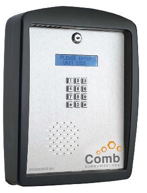
3 MAJOR COMPONENT LIST 1. Microphone 2. Plastic Enclosure 3. LED Lighting (Std White led) 4. Back Plate mounting holes 5. Main PCB 6. Battery (12v 0.8AH) 7. Transformer (15v 1amp) 8. Non Key alike barrel lock 9. Display (Blue writing white backlight) 10. Metal Keypad 11. Speaker (45Ω 1w) 12. Stainless Steel Front plate 13. Gooseneck mounting hole 14. Enclosure mounting hole 15. Stainless steel back plate 16. Gooseneck with mounting
4 WALL MOUNTING INSTRUCTIONS Remove the front plate from the plastic enclosure. Unscrew the back plate from the enclosure. Screw the back plate to the wall. It is recommended that an 8mm Nail in anchors be used. Bring 220v AC cabling in through the middle hole. Once back plate is securely in place, screw the plastic enclosure to the back plate, feeding the cable though the middle hole, with the 4 mounting screws provided. Replace the front plate. FITTING A GOOSENECK Remove the front plate from the plastic enclosure. Unscrew the back plate from enclosure. Plant the gooseneck securely into the ground and ensure that 220v ac is fed through the centre hole. Screw the plastic enclosure to the gooseneck with the 4 mounting screws provided, feeding the cable though the middle hole. Replace the front plate.
5 PCB LAYOUT DIAGRAM
6 HOW TO WIRE YOUR SYSTEM The M2 unit is supplied with some wiring in place. Before wiring the unit ensure that the Battery is unplugged and that the 220V mains supply is not powered. Refer to the PCB diagram. RELAYS and INPUTS (Defaults) 1. Main Gate Trigger Wire to Relay 1, the relay has NO and NC contacts 2. Pedestrian Gate Trigger - Wire to Relay 1, the relay has NO and NC contacts 3. Exit Control - Wire to Relay 1, the relay has NO and NC contacts 4. Input Triggers Wire Input triggers to the Inputs IN1 to IN6; configure these INPUTS via the Website GSM ANTENNA Connect the GSM antenna. The Antenna may be extended with GSM cable extensions. Please also refer to the section on GSM Antenna installation. FRONT PLATE Insert the frontplate teeth into the plastic enclosure and connect up the following connectors: 1. Keypad and display harness, Flat ribbon cable 2. Speaker cable 2 pin connector Note the Microphone connector, LED illumination and 16 VAC should already be in place EXTERNAL KEYPADS The external keypads are connected to the 4 way screw terminals labelled, +, -, FRX and CH2, wire these terminals to the corresponding terminals on the keypads. Up to 2 keypads can be wired in parallel to the screw terminals. SIMCARD The MK II can operate with a SIMCARD or embedded SIMCHIP. Make sure that the SIMCARD is working by placing it inside a regular cell phone and making or receiving a call. If operating from a SIMCARD ensure that the SIMCARD is in place and the sliding tray is securely latched. Should you wish to use the SIMCHIP instead, please contact Comb - communications to have this service activated? You may be asked for the SIMCHIP ICCID, use the *#0010 supervisor code to access this 20 digit number. Please note that the *#0010 command works on the current SIM device, so remove the regular SIMCARD, type *#0004 to reboot and then type *#0010 to get the SIMCHIP CCID.
7 POWER SYSTEM CHECKS 1. Wire the 220VAC mains to the lightning protection unit, observe the earth and polarity. Apply the mains power. 2. Connect the battery to the battery connector. The MK II will now boot up and after about 1 minute is ready to operate. Make sure the installation is good by checking the following: GSM signal : type *#0002. The signal should be between 17 and 31. If not you may need a better GSM antenna or the GSM antenna wiring is faulty. Try to re-orientate the Antenna. BATTERY: type *#0005 to check the battery voltage, it should be between 13.0V and 14.5V. MKII ID Use the supervisor code *#0008 to obtain the unit ID. This 8 character number is required to setup the unit on the website. Refer to the Mk II user manual to configure and test your system. REBOOTING the MKII Should the MKII unit fail to respond or hang-up The MK II can be rebooted from the front panel with a supervisor code *#0004. If the keypad is not responsive, remove the battery plug and remove the mains power or 16VAC power for 10 seconds then re-apply. ANTENNA INSTALLATION GUIDELINES The M2 Intercom requires a Multi-band GSM antenna. This will differ for your Country of installation. Proper GSM antenna installation is essential for correct system performance. Various options are provided for different scenarios for cable length and antenna gain. The provided antenna is suitable for most applications. When installing the GSM antenna the following guidelines must be adhered to The GSM signal strength (accessed from the keypad via *#0002 command should be between 16 and 31. Lower than 16 is a poor GSM signal and will impair the M2 system performance.
8 The maximum GSM cable length should not exceed 10m, and should be kept as short as possible. Longer runs will require the use of higher gain antennae The GSM antenna can be extended from its standard length with a Combapproved RF cable extensions. This will ensure proper RF impedance matching and signal quality. Do not extend the GSM antenna by joining cables with solderd High Gain GSM antennae may be used to boost the signal strength The Antenna must not be installed inside any metal box or mesh cage as this will degrade the RF performance Always try to re-orientate or elevate the antenna if the signal strength is low Try reduce physical access to the antenna for the purposes of reducing vandalism attempts. Mount the antenna inside the secured premises SUPERVISOR CODES Supervisor codes are available on the B1000 and G2 models. Code Description *#0000 Display all supervisor codes *#0001 Firmware version *#0002 GSM signal strength *#0003 Synchronise the Unit. *#0004 Keypad reboot. *#0005 Battery voltage. *#0006 Configuration method. *#0007 Modem initialization *#0008 PCA Serial number. *#0009 Manual configuration if enabled. *#0010 ICCID number *#0011 Modem IMEI number
9 SUPPORT Please feel free to our support department at should you need any assistance in this regard Disclaimer There is no warranty for the contents hereof, to the extent permitted by applicable law. The document is provided "as is" without warranty of any kind, either expressed or implied, including, but not limited to, the implied warranties of merchantability and fitness for a particular purpose. The entire risk as to the quality of the document, and examples and instructions therein is with you. Should the document or instructions and examples therein prove defective, you assume the cost of all necessary servicing, repair or correction. In no event unless required by applicable law or agreed to in writing will any copyright holder, or any other party who may modify and/or redistribute the documentation as permitted by its licence, be liable to you for damages, including any general, special, incidental or consequential damages arising out of the use or inability to use the documentation (including but not limited to loss of data or data being rendered inaccurate or losses sustained by you or third parties), even if such holder or other party has been advised of the possibility of such damages.
PixController, Inc. Wireless Vibration Sensor For Indoor and Outdoor Use
 PixController, Inc. Wireless Vibration Sensor For Indoor and Outdoor Use Model: SEN-440 User s Manual Version 1.00 WARRANTY REGISTRATION PixController, Inc. warrants products sold by it and guarantees
User Manual. ProRF Encoder Transmitter & Receiver
 User Manual ProRF Encoder Transmitter & Receiver WARRANTY Accurate Technology, Inc. warrants the ProScale Systems against defective parts and workmanship for 1 year commencing from the date of original
CAB LINK User Guide. Radial Engineering Ltd Kebet Way, Port Coquitlam BC V3C 5M5 Tel: Fax:
 CAB LINK User Guide TM 15 Kebet Way, Port Coquitlam BC V3C 5M5 Tel: 60-92-1001 Fax: 60-92-1010 Email: info@radialeng.com Cab-Link Speaker Cabinet Combiner FEATURES Features... 1 Making Connections...2-3
SIR, RADAN and UtilityScan are registered trademarks of Geophysical Survey Systems, Inc..
 Copyright 2001-2017 Geophysical Survey Systems, Inc. All rights reserved including the right of reproduction in whole or in part in any form Published by Geophysical Survey Systems, Inc. 40 Simon Street
Field Service Spares Procedure Replacement Coax Switch Kit, 8897B, 9497B, 14400B, ST88, ST94 & ST144
 1. Brief Summary: Troubleshooting document for diagnosing a fault with replacing the coax switch assembly on the 8897B, 9497B, 14400B, ST88, ST94 and ST144 antennas. 2. Checklist: Verify the Band of the
Transmitter. User Manual. Firmware version 1.0 and greater
 ProRF SPC Transmitter User Manual Firmware version 1.0 and greater FCC NOTICE This equipment has been tested and found to comply with the limits for a class B digital device, pursuant to part 15 of the
2.4 GHz 2.5 GHz FlexNotch 2 dbi Antenna w/u.fl Cable, 100mm
 2.4 GHz 2.5 GHz FlexNotch 2 dbi Antenna w/u.fl Cable, 100mm ORDERING INFORMATION Order Number Description 001-0015 2.4 GHz FlexNotch Antenna w/u.fl Cable, 100mm 001-0023 2.4GHz FlexNotch Antenna w/ MHF4L
Directed Energy, Inc Oakridge Dr., Suite 100, Fort Collins, CO
 PCO-7121 Laser Diode Driver Module Operation Manual Directed Energy, Inc. 1609 Oakridge Dr., Suite 100, Fort Collins, CO 80525 sales@ixyscolorado.com www.ixyscolorado.com Contents Contents... 3 Safety...
MaxLite LED Self-Driven LiteBars
 Accessories Length: 4, 12, 40 Connector Box Straight Joiner Wire Joiner Mounting Clip Distribution Box Left Joiner Wire Joiner with Plug length: 40 Magnet Bracket Right Joiner End Cap Rotation Bracket
Broadband Step-Up Transformer. User Manual
 Broadband Step-Up Transformer User Manual 990-1930 09/2004 Introduction Introduction About this unit The APC Step-Up Transformer provides 220 V power from 60 VAC Broadband cable systems. Safety Electrical
ET Water SmartWorks Panel Installation Guide
 ET Water SmartWorks Panel Installation Guide You are installing a new piece of equipment that retrofits into an existing irrigation controller in order to create a weather-based irrigation control system.
Instruction Manual Model M Switch, DPDT, Manual Select
 Instruction Manual Model 1582-70M Switch, DPDT, Manual Select November 2018 Rev 0 STATUS MODEL 1582 CROSS TECHNOLOGIES INC. MANUAL SELECT POWER Data, drawings, and other material contained herein are proprietary
Performance Series 360w 4-CH Amplifier Kit For Harley Street Glide with Lower/Rear Speakers JMAA-3600HC14-SG
 Performance Series 360w 4-CH Amplifier Kit For 2014-2018 Harley Street Glide with Lower/Rear s # JMAA-3600HC14-SG 2017 J&M Corporation. All rights reserved. 9/17 Installation and Operation Instructions
Instruction Sheet REB SERIES. Rotating Sliding Base REB18
 Instruction Sheet REB SERIES Rotating Sliding Base REB14 REB18 THANK YOU Thank you for purchasing the REB Series Rotating Sliding Base. Please read these instructions thoroughly before installing this
WSA 8 BOX RELE Installation Manual
 WSA 8 BOX RELE Installation Manual Description: The WSA Barrier consists of 2 aluminum bars containing electronics and 2 cases with battery adapters. The receiver and the transmitter are both supplied
Installation and Operation Manual MSI. Multi-Sensor Interface Hub. Interface Module for all Sensors Network and Wireless CAUTION
 Installation and Operation Manual MSI Multi-Sensor Interface Hub Interface Module for all Sensors Network and Wireless CAUTION This equipment complies with the limits for a Class B digital device, pursuant
BCV-1203 Barcode Verification System Users Guide Version 1.2
 BCV-1203 Barcode Verification System Users Guide Version 1.2 6 Clock Tower Place Suite 100 Maynard, MA 01754 USA Tel: (866) 837-1931 Tel: (978) 461-1140 FAX: (978) 461-1146 http://www.diamondt.com/ Liability
model 101 single channel microphone preamplifier owner s manual Rev C
 2434 30th street, boulder, CO 80306-0204 USA tel 303.443.7454 fax 303.444.4634 info@gracedesign.com / www.gracedesign.com single channel microphone preamplifier Rev C all contents Grace Design/ Lunatec
PRO Professional Radio Control Series Applications
 204 205 Ready to Use Remote Control 4, 8/16 Channel Systems Range: Up to 200 metres at 433MHz Up to 1,000 metres at 433MHz NB Relay Outputs: Momentary, Latching, Timed Receiver IP65 Applications Lighting
f i r e - p a r t s. c o m
 Model: CON 1001-1 INSTALLATION AND OPERATING INSTRUCTIONS SINGLE-FUNCTION WIRELESS REMOTE CONTROL SYSTEM FOR OPERATING VALVES WITH ON/OFF LATCHING SOLENOIDS IF YOU CANNOT READ OR UNDERSTAND THESE INSTALLATION
3M Locator Plate
 M Locator Plate 44-119 Instructions for the Assembly of Series 158 2 mm x 2 mm Socket Connectors 1.0 General The Locator Plate 44-119 is designed for rapid assembly of all available pin count positions
SA-505 Supervised Wireless Multi-Layer Repeater Installation Manual 1. General Description
 SA-505 Supervised Wireless Multi-Layer Repeater Installation Manual 1. General Description The SA-505 is a sophisticated wireless learning and layering repeater for indoor use. It extends the range of
Model 3116 Double-Ridged Waveguide Horn
 Model 3116 Double-Ridged Waveguide Horn MANUAL EMC TEST SYSTEMS, L.P. MARCH 2002 EMC Test Systems, L.P. reserves the right to make changes to any product described herein in order to improve function,
AIU-2 Installation Manual
 AIU-2 Installation Manual RESEARCH CONCEPTS INC. 9501 Dice Lane Lenexa, Kansas 66215 USA VOICE: (913) 422-0210 FAX: (913) 422-0211 www.researchconcepts.com support@researchconcepts.com Contents subject
2.4 / 5.5 GHz FlexPIFA 3 dbi Antenna w/u.fl Cable, 100mm
 2.4 / 5.5 GHz FlexPIFA 3 dbi Antenna w/u.fl Cable, 100mm ORDERING INFORMATION Order Number Description 001-0016 2.4 / 5.5 GHz FlexPIFA Antenna w/u.fl cable, 100mm 001-0021 2.4 / 5.5 GHz FlexPIFA Antenna
JMAA-3600HR16-UL. Installation and Operation Instructions. Performance Series 360w RMS 4-Channel Amplifier Kit For Harley RoadGlide Ultra
 Performance Series 360w RMS 4-Channel Amplifier Kit For 2016-2018 Harley RoadGlide Ultra # JMAA-3600HR16-UL 2017 J&M Corporation. All rights reserved. 9/17 Installation and Operation Instructions Product
Digi-Stop. Installation & Operation
 Digi-Stop Installation & Operation WARRANTY Accurate Technology, Inc. warrants the ProScale Systems against defective parts and workmanship for 1 year commencing from the date of original purchase. Upon
Model 3110B Biconical Antenna
 Established 1981 Advanced Test Equipment Rentals www.atecorp.com 800-404-ATEC (2832) Archived 3/18/10 Model 3110B Biconical Antenna MANUAL EMC TEST SYSTEMS, L.P. MARCH 2002 EMC Test Systems, L.P. reserves
Hopper and Drive Components
 January, 07 Lit. No. 7586, Rev. 00 Hopper and Drive Components Model SP-00- & SP-5- Low-Profile Tailgate Spreader Parts List This manual is for SnowEx SP-00- & SP-5- tailgate spreaders with serial numbers
UNICOM 2500 UNICOM Installation Operation Programming. Universal Communication Converter
 User Manual UNICOM 2500 Installation Operation Programming Universal Communication Converter UNICOM 2500 Electro Industries/GaugeTech 1800 Shames Drive Westbury, New York 11590 Tel 516.334.0870 Fax 516.338.4741
OMEGA. Communications Interface Cabinet. Antenna Installation Manual
 Ω OMEGA Communications Interface Cabinet Antenna Installation Manual 0049-0706-004 The products and programs described in this User s Guide are licensed products of Telenetics Corporation. This User s
PTT- Z or PTT-U PUSH-TO-TALK Specification
 Federal Communication Commission Interference Statement This equipment has been tested and found to comply with the limits for a Class B digital device, pursuant to Part 15 of the FCC Rules. These limits
JAMP-630HC14-ULP. Installation and Operation Instructions. ROKKER XXRP 630w Amplifier Kit For Harley Ultra/Ultra Ltd.
 ROKKER XXRP 630w Amplifier Kit For 2014-2018 Harley Ultra/Ultra Ltd. Fairing # JAMP-630HC14-ULP 2017 J&M Corporation. All rights reserved. 9/17 Installation and Operation Instructions Product Description
Effective: June, 2000 EX-1821 Satellite Display Unit Receiver Installation Manual Models: 4643-*-* 4644-*-9 Since 1937
 Effective: June, 2000 LevelPRO Satellite Display Unit Receiver Installation Manual Models: 4643-*-* 4644-*-9 Since 1937 The information contained in this manual was accurate at the time of release. Specifications
Keyed latch. Cover. Service Outlet 115VAC, 15A. Plastic base. Unpack. Operator. the Operator
 Service Outlet Quick Start Steps Keyed latch Cover 115VAC, 15A Plastic base Operator Unpack the Operator Site Planning and Operator Installation The illustrations and instructions presented in this guide
bhi bhi Sound Engineering Solutions from bhi Sound Engineering Solutions NEDSP1061-PCB bhi ltd 22 Woolven Close Burgess Hill West Sussex RH15 9RR
 Sound Engineering Solutions Page 24 bhi bhi ltd 22 Woolven Close Burgess Hill West Sussex RH15 9RR tel: +44 (0)845 217 9926 fax: +44 (0)845 217 9936 sales@bhi-ltd.co.uk www.bhi-ltd.co.uk Sound Engineering
PROFLY / PROBLADE Professional Radio Control PRO-BLADE8
 PRO-BLADE8 Ready to Use Remote Control 8 Channel Systems Range: PROFLY Up to 100 metres PROBLADE Up to 500 metres Relay Outputs: Momentary, Latching, Timed Receiver IP65 Applications Lighting Control General
USER MANUAL. Maxwell Technologies BOOSTCAP Energy Storage Modules. User Manual for 15V Modules: 20 F, 23 F, 53 F, 58 F 15 Volts DC
 USER MANUAL Maxwell Technologies BOOSTCAP Energy Storage Modules User Manual for 15V Modules: 20 F, 23 F, 53 F, 58 F 15 Volts DC BPAK0020 P015 B1 BPAK0023 E015 B1 BPAK0052 P015 B1 BPAK0052 P015 B2 BPAK0058
Performance Series 360w Amplifier Kit For Harley RoadGlide with Lower/Rear Speakers JMAA-3600HR15-RC
 Performance Series 360w Amplifier Kit For 2015-2018 Harley RoadGlide with Lower/Rear s # JMAA-3600HR15-RC 2017 J&M Corporation. All rights reserved. 9/17 Installation and Operation Instructions Product
2.4 GHz 2.5 GHz FlexPIFA 2 dbi Antenna w/u.fl Cable, 100mm
 2.4 GHz FlexPIFA Antenna, 1mm 2.4 GHz 2.5 GHz FlexPIFA 2 dbi Antenna w/u.fl Cable, 1mm ORDERING INFORMATION Order Number Description 1-14 2.4 GHz FlexPIFA Antenna w/u.fl Cable, 1mm 1-22 2.4 GHz FlexPIFA
VideoEase VGA 1x4 Distribution Hub (500150, ) Installation Guide
 Installation Guide") VideoEase VGA 1x4 Distribution Hub (500150, 500151) Installation Guide P/N: 94-000624-A SE-000605-A Table of Contents 1. Overview...3 1.1. Description...3 1.2. Features...4 2. Technical Specifications...5
VideoEase VGA 1x4 Distribution Hub (500150, 500151) Installation Guide P/N: 94-000624-A SE-000605-A Table of Contents 1. Overview...3 1.1. Description...3 1.2. Features...4 2. Technical Specifications...5
PCO-7114 Laser Diode Driver Module Operation Manual
 PCO-7114 Laser Diode Driver Module Operation Manual Directed Energy, Inc. 1609 Oakridge Dr., Suite 100, Fort Collins, CO 80525, (970) 493-1901 sales@ixyscolorado.com www.ixyscolorado.com Manual Document
Firmware Version d & higher Installation & Operation
 DIGI LCD Readout Firmware Version d 2.100 & higher Installation & Operation READOUT SERIAL # SCALE SERIAL # TO MAXIMIZE THE ACCURACY OF YOUR SYSTEM, THE FOLLOWING PROGRAMMING PARAMETER HAS BEEN PRE-CONFIGURED
Model 1791 VHF Radio User's Manual
 Model 79 VHF Radio User's Manual ALL WEATHER INC 65 NATIONAL DRIVE SACRAMENTO, CA 95834 WWW.ALWEATHERINC.COM 79 VHF RADIO USER'S MANUAL CONTENTS INTRODUCTION... Description... Transmitter Module... Power
Distribution Amplifiers 1
 Distribution Amplifiers 1-30dB PUT 49-750 MHz 43 db GA POWER DOUBLED P/N: 1002705 REVERSE GA M MAX DESCRIPTION The R.L. DRAKE models DA8642, DA8632,, and DA7533, are broadband distribution amplifiers designed
User Guide DIRECT-DRIVE
 DIRECT-DRIVE User Guide 1588 Kebet Way, Port Coquitlam BC V3C 5M5 Tel: 604-942-1001 Fax: 604-942-1010 Email: info@radialeng.com JDX Direct-Drive Amp Simulator and Direct Box Overview... 1 Features... 2
3M Shielded Controlled Impedance (SCI) Latch/Eject Header 2 mm Development Kit Instructions
 Latch/Eject Header 2 mm Development Kit Instructions") 3M Shielded Controlled Impedance (SCI) Latch/Eject Header 2 mm Development Kit Instructions Contents 1.0 Purpose....................................... 1 2.0 Development Kits..................................
3M Shielded Controlled Impedance (SCI) Latch/Eject Header 2 mm Development Kit Instructions Contents 1.0 Purpose....................................... 1 2.0 Development Kits..................................
DL102 Counter Loop Amplifier
 DL102 Counter Loop Amplifier USER MANUAL MAN 234A Contents Overview...3 System Includes...3 Maintenance and Recycling Instructions...3 Safety Information...4 Quick Setup...5 Setup...6 Loop Amplifier...6
WARRANTY. Long Range Systems, LLC, 20 Canal St, Suite 4N, Franklin, NH 03235
 WARRANTY Long Range Systems, Inc. warrants the trap release product against any defects that are due to faulty material or workmanship for a one-year period after the original date of consumer purchase.
PRODUCT SAFETY SOLUTIONS MODEL HWI-01. Model HWI-01 Serial Number:
 USER S MANUAL HOT WIRE IGNITION TESTER MODEL HWI-01 Model HWI-01 Serial Number: 1 HWI-01 HOT WIRE IGNITION TESTER IMPORTANT INSTRUCTIONS - - SAVE THESE INSTRUCTIONS Introduction Thank you for choosing
Cross-Connect Interface
 Cross-Connect Interface User Manual Document #: 050-015-0036R01 November 2006 TASC Systems Inc. Langley, BC Canada Cross-Connect System User Manual Preface This document describes the installation, commissioning
Disclaimers. Important Notice
 Disclaimers Disclaimers Important Notice Copyright SolarEdge Inc. All rights reserved. No part of this document may be reproduced, stored in a retrieval system, or transmitted, in any form or by any means,
MODEL NC221 MOBILE TWO-TONE SEQUENTIAL DECODER INSTRUCTION MANUAL
 15385 Carrie Drive Grass Valley, CA 95949 Office: (530) 477-8400 Tech. Support: (530) 477-8402 FAX: (530) 477-8403 Sales: (800) 874-8663 Email: tech@norcommcorp.com Web:www.norcommcorp.com MODEL NC221
DYNAMIC ENGINEERING 435 Park Dr., Ben Lomond, Calif Fax Est.
 DYNAMIC ENGINEERING 435 Park Dr., Ben Lomond, Calif. 95005 831-336-8891 Fax 831-336-3840 http://www.dyneng.com sales@dyneng.com Est. 1988 User Manual PIM-Universal-IO PMC IO Module PIM w/ SCSI II Bezel
Owner s Manual TRANCE TRANCE AUDIO. Trance Audio, Inc. P.O. Box 256 Santa Cruz, CA Phone: (831)
") Owner s Manual AUDIO Trance Audio, Inc. P.O. Box 256 Santa Cruz, CA 95061 Phone: (831) 688-9699 www.tranceaudio.com CHANGING THE BATTERIES The Amulet can run for up to 50 hours on a pair of standard nine-volt
Owner s Manual AUDIO Trance Audio, Inc. P.O. Box 256 Santa Cruz, CA 95061 Phone: (831) 688-9699 www.tranceaudio.com CHANGING THE BATTERIES The Amulet can run for up to 50 hours on a pair of standard nine-volt
SKY LF: GHz SP10T Switch with GPIO Interface
 PRELIMINARY DATA SHEET SKY13404-466LF: 0.4-2.7 GHz SP10T Switch with GPIO Interface Applications 2G/3G multimode cellular handsets (UMTS, CDMA2000, EDGE, GSM) Embedded data cards Features Broadband frequency
Model TR-5 Fixture Kit INSTRUCTION MANUAL. CheckSum, LLC th Street NE Arlington, WA (360) Web site:
 Web site:") Model TR-5 Fixture Kit INSTRUCTION MANUAL CheckSum, LLC 6120 195th Street NE Arlington, WA 98223 (360) 435-5510 Web site: www.checksum.com P/N 4400-007 Revision 20150113 Copyright 1992-2015 - CheckSum
Model TR-5 Fixture Kit INSTRUCTION MANUAL CheckSum, LLC 6120 195th Street NE Arlington, WA 98223 (360) 435-5510 Web site: www.checksum.com P/N 4400-007 Revision 20150113 Copyright 1992-2015 - CheckSum
Digi-Stop. User Manual for: Digi-Stop. Digital Readout Firmware version d & Higher
 Digi-Stop User Manual for: Digi-Stop Digital Readout Firmware version d 2.000 & Higher Warranty Accurate Technology, Inc., warrants this product against defective parts and workmanship for 1 year commencing
Firmware Version d & higher Installation & Operation
 DIGI LCD Readout Firmware Version d 2.100 & higher Installation & Operation Warranty Accurate Technology, Inc., warrants this product against defective parts and workmanship for 1 year commencing from
Classic Series Public Address Amplifiers C10 & C20 Models
 Classic Series Public Address Amplifiers C10 & C20 Models Installation and Use Manual 2009 Bogen Communications, Inc. All rights reserved. Specifications subject to change without notice. 54-5978-01B 0901
Digi-Fence. User Manual for: Digi-Fence (all models) Digital Readout Firmware version d & Higher
 Digital Readout Firmware version d & Higher") Digi-Fence User Manual for: Digi-Fence (all models) Digital Readout Firmware version d 2.000 & Higher Warranty Accurate Technology, Inc., warrants this product against defective parts and workmanship for
Digi-Fence User Manual for: Digi-Fence (all models) Digital Readout Firmware version d 2.000 & Higher Warranty Accurate Technology, Inc., warrants this product against defective parts and workmanship for
305 Stimulus Isolator. Description
 Description The Model 305 Stimulus Isolator utilizes photon coupling to provide nearly ideal isolation of the pulse and train outputs of the WPI Series 300 Anapulse Stimulators. Two Model 305 units are
Quick Start Guide. HMa-941. Plug-On Transmitter. For FCC Part 74 licensed operators
 Quick Start Guide HMa-941 Plug-On Transmitter Digital Hybrid Wireless U.S. Patent 7,225,135 For FCC Part 74 licensed operators Fill in for your records: Serial Number: Purchase Date: This guide is intended
JMAA-1800HR15. Installation and Operation Instructions. 180w Performance Series Amplifier Kit For Harley RoadGlide/ Ultra
 180w Performance Series Amplifier Kit For 2015-2018 Harley RoadGlide/ Ultra # JMAA-1800HR15 2017 J&M Corporation. All rights reserved. 9/17 Installation and Operation Instructions Product Description This
Hopper and Drive Components
 February, 07 Lit. No. 770, Rev. 0 Hopper and Drive Components Model TS-00- & TS-00-EG- Low-Profile Tailgate Spreader Parts List This manual is for TurfEx TS-00- & TS-00-EG- tailgate spreaders with serial
Grounding and Utility Enclosure
 Grounding and Utility Enclosure DXE-UE-2P DXE-UE-2P-INS Rev 1f DX Engineering 2017 1200 Southeast Ave. - Tallmadge, OH 44278 USA Phone: (800) 777-0703 Tech Support and International: (330) 572-3200 Fax:
Far End Device II Model 1342
 3 Far End Device II Model 1342 Operating Instructions Optimized for ADSL2+ May 2007 78-8130-0876-6-C Table of Contents Introduction...3 Power-up...4 Connecting the 3M Far End Device II...5 Installing,
Digital Lighting Systems, Inc.
 PD408-AN0-277 ANALOG 0-0 V 0-0V analog control 4 Channel x 2250 W Dimmer & Switch Packs 220/240/277 Volts operation PD408-AN0-277 4 circuit Analog -0V 4 x 8 A. Dimmer pack Serial Number Digital Lighting
HydroLynx Systems, Inc.
 Model 50386R-RP Receiver and Repeater Instruction Manual Document No: A102684 Document Revision Date: August, 2006 Receiving and Unpacking Carefully unpack all components and compare to the packing list.
LT3000 ULTRASONIC LEVEL TRANSMITTER
 LT3000 ULTRASONIC LEVEL TRANSMITTER Owner s Manual Specifications Installation Calibration Troubleshooting Warranty Drawings Distributed By: iprocessmart.com 14262 Doolittle Drive San Leandro, CA 94577
Lazerpoint TM RF RX-91 Basic Receiver Installation Instructions
 Lazerpoint TM RF RX-91 Basic Receiver Installation Instructions Ver. 1.01 Section 1 General Description Camden Lazerpoint Radio Controls comprise the following models: - CM-TX-9 Wall switch ready transmitter
SD-996C-NUQ. Universal Door Strike. Manual
 SD-996C-NUQ Universal Door Strike Manual 43RG UL Listed. Field selectable for fail-safe or fail-secure Includes 3 faceplates for nearly any type of door: Aluminum frames Hollow metal door frames Wood door
AN PR533 USB stick - Evaluation board. Application note COMPANY PUBLIC. Rev May Document information
 PR533 USB stick - Evaluation board Document information Info Content Keywords PR533, CCID, USB Stick, Contactless Reader Abstract This application notes describes the PR533 evaluation board delivered in
Synthesized Base Station Transmitter
 BST-25 OPERATOR S MANUAL (216 MHz) Synthesized Base Station Transmitter 357 West 2700 South Salt Lake City, Utah 84115 Phone: (800) 496-3463 Fax: (801) 484-6906 http://www.comtek.com INTRODUCTION BST-25
Copyright Teletronics International, Inc. Patent Pending
 Copyright 2003 By Teletronics International, Inc. Patent Pending FCC NOTICES Electronic Emission Notice: This device complies with Part 15 of the FCC rules. Operation is subject to the following two conditions:
2007 MFJ ENTERPRISES, INC.
 Model MFJ-643 INSTRUCTION MANUAL CAUTION: Read All Instructions Before Operating Equipment MFJ ENTERPRISES, INC. 300 Industrial Park Road Starkville, MS 39759 USA Tel: 662-323-5869 Fax: 662-323-6551 VERSION
C S Technology Ltd. cstech.co.uk. DTMF decoder kit with relay output, opto coupled input & Morse transpond.
 C S Technology Ltd cstech.co.uk DTMF decoder kit with relay output, opto coupled input & Morse transpond. Our DTMF Opto decoder kit has one relay output offering clean contacts, and one Opto coupled input
Model TR-5 Fixture Kit INSTRUCTION MANUAL. CheckSum, LLC th Street NE Arlington, WA (360) Web site:
 Web site:") Model TR-5 Fixture Kit INSTRUCTION MANUAL CheckSum, LLC 6120 195th Street NE Arlington, WA 98223 (360) 435-5510 Web site: www.checksum.com P/N 4400-007 Revision 201409223 Copyright 1992-2014 - CheckSum
Model TR-5 Fixture Kit INSTRUCTION MANUAL CheckSum, LLC 6120 195th Street NE Arlington, WA 98223 (360) 435-5510 Web site: www.checksum.com P/N 4400-007 Revision 201409223 Copyright 1992-2014 - CheckSum
INSTALLATION AND MAINTENANCE MANUAL FOR GROUND MONITOR GM-250 COPYRIGHT 1983 AMERICAN MINE RESEARCH, INC.
 INSTALLATION AND MAINTENANCE MANUAL FOR GROUND MONITOR GM-250 COPYRIGHT 1983 AMERICAN MINE RESEARCH, INC. MANUAL PART NUMBER 180-0036 ORIGINAL: 1-17-83 REVISION: B (8-26-86) NOT TO BE CHANGED WITHOUT MSHA
Owner s Manual HPA-DAC2. HPA-DAC2 Dante Accessory Card. AtlasIED.com
 Owner s Manual 1 AtlasIED.com Owner s Manual Description The accessory card is designed to work in conjunction with HPA Series 2-channel amplifiers. The is a 2-input Dante receiver that features digital
bhi bhi DSP Noise Cancelling Products DSP Noise Cancelling Products NEDSP1061-PCB bhi ltd PO Box 318 Burgess Hill West Sussex RH15 9NR
 DSP Noise Cancelling Products bhi bhi ltd PO Box 318 Burgess Hill West Sussex RH15 9NR tel: +44 (0)845 217 9926 fax: +44 (0)845 217 9936 sales@bhi-ltd.com www.bhi-ltd.com DSP Noise Cancelling Products
Important Safety Information
 USER MANUAL Important Safety Information Before using Zuma R300, please be sure to read all operating instructions carefully. Read, follow, and keep these instructions. Heed all warnings. Do not expose
Single Flex and Double Flex Couplings (i)
") Single Flex and Double Flex Couplings (i) FORM NO. L00G00 In accordance with Nexen s established policy of constant product improvement, the specifications contained in this manual are subject to change
Single Flex and Double Flex Couplings (i) FORM NO. L00G00 In accordance with Nexen s established policy of constant product improvement, the specifications contained in this manual are subject to change
Instruction Manual MT-945SL Four Channel Video Transmitter With Two Bi-Directional Data Channels
 Instruction Manual MT-945SL Four Channel Video Transmitter With Two Bi-Directional Data Channels Copyright 2006, American Fibertek, Inc. 0307JD Table of Contents Functional Description... 3 Installation...
Installation & User Guide. For Powering Distributed Audio Systems A45-X2 TWO CHANNEL AMPLIFIER
 Installation & User Guide For Powering Distributed Audio Systems TWO CHANNEL AMPLIFIER A45-X2 A45-X2 TWO CHANNEL AMPLIFIER TABLE OF CONTENTS Features...1 Product Overview...2 Package Contents...4 Preparing
JAMP-700HR15-RCP. Installation and Operation Instructions. ROKKER XXRP 700w Amplifier Kit For Harley RoadGlide with Lower/Rear Speakers
 ROKKER XXRP 700w Amplifier Kit For 2015-2018 Harley RoadGlide with Lower/Rear s # JAMP-700HR15-RCP 2018 J&M Corporation. All rights reserved. 4/18 Installation and Operation Instructions Product Overview
Astra-R Kit Wireless Alarm System Operation Manual
 Astra-R Kit Wireless Alarm System Operation Manual This operation manual describes principles of functioning, proper use, maintenance and service for the wireless alarm system Astra- R Kit (Figure 1).
AM95 Installation Guide
 1321 S. State College Blvd., Fullerton, CA 92831 USA Included Components: Maximum Flat Panel Weight: 95 lb. / 43.1 kg. M4 X 25mm M5 X 25mm M6 X 12mm (Qty 2) M6 X 25mm M8 X 25mm Allen Key Plastic Cover
SD-996C-NUVQ Electric Door Strike with Vertical Adjustment
 SD-996C-NUVQ Electric Door Strike with Vertical Adjustment Manual 43RG Features: 12/24 VDC Operation Vertical adjustable deadbolt opening, sliding shim keeper, and deadlatch ramp accommodates a wide range
SKY LF: GHz SP10T Switch with GPIO Interface
 DATA SHEET SKY13404-466LF: 0.4-2.7 GHz SP10T Switch with GPIO Interface Applications 2G/3G multimode cellular handsets (UMTS, CDMA2000, EDGE, GSM) Embedded data cards Features Broadband frequency range:
DigiSpeed DC-03. Isolated Control Voltage Generator User s Guide. PCB: DC-03 V3.0 Firmware: Ver: 3.0 Mach3: Ver: 1.84
 DigiSpeed DC-03 - Users Guide Page 1 Updated: 29. April 2009 DigiSpeed DC-03 Isolated Control Voltage Generator User s Guide PCB: DC-03 V3.0 Firmware: Ver: 3.0 Mach3: Ver: 1.84 DigiSpeed DC-03 - Users
XRS-330C Quick Start Guide
 XRS-330C Quick Start Guide Compact Hideaway 80 Channel UHF CB Radio The full Instruction Manual can be downloaded from www.gme.net.au In the box XRS-330C 5 watt UHF CB radio Mounting cradle (MK031) XRS
HandPunch Installation Guide
 HandPunch Installation Guide www.centraltimeclock.com HandPunch 3000/4000 Manual Planning an Installation Site Preparation Before you begin installation, check the site blueprints, riser diagrams, and
SDI SPECTRADYNAMICS, INC. LOW NOISE FREQUENCY REFERENCE OPERATING MANUAL
 SPECTRADYNAMICS, INC. LOW NOISE FREQUENCY REFERENCE LNFR-100E OPERATING MANUAL SPECTRADYNAMICS, INC 1849 Cherry St. Unit 2. Louisville, CO 80027 Phone: (303) 665-1852 Fax: (303) 604-6088 www.spectradynamics.com
MFJ ENTERPRISES, INC.
 Model MFJ-2912 INSTRUCTION MANUAL CAUTION: Read All Instructions Before Operating Equipment MFJ ENTERPRISES, INC. 300 Industrial Park Road Starkville, MS 39759 USA Tel: 662-323-5869 Fax: 662-323-6551 VERSION
AN Ohm FM LNA for embedded Antenna in Portable applications with BGU7003W. Document information. Keywords Abstract
 for embedded Antenna in Portable applications with BGU7003W Rev. 1.0 15 July 2011 Application note Document information Info Keywords Abstract Content BGU7003W, LNA, FM, embedded Antenna The document provides
ANTENNA DESIGN GUIDE. Last updated March 8 th, The information in this document is subject to change without notice.
 Last updated March 8 th, 2012 330-0092-R2.0 Copyright 2012 LS Research, LLC Page 1 of 22 Table of Contents 1 Introduction... 3 1.1 Purpose & Scope... 3 1.2 Applicable Documents... 3 1.3 Revision History...
EXECUTE Shiloh Road Alpharetta, Georgia (770) FAX (770) Toll Free
 FAX (770) Toll Free") Instruction Manual Model 1586-06 RF Attenuator May 2009 Rev A 1 2 3 12.5 53.5 16.3 MODEL 1586 RF ATTENUATOR CROSS TECHNOLOGIES INC. EXECUTE PS1 PS2 Data, drawings, and other material contained herein are
Instruction Manual Model 1586-06 RF Attenuator May 2009 Rev A 1 2 3 12.5 53.5 16.3 MODEL 1586 RF ATTENUATOR CROSS TECHNOLOGIES INC. EXECUTE PS1 PS2 Data, drawings, and other material contained herein are
ANTENNA DESIGN GUIDE. Last updated February 11, The information in this document is subject to change without notice.
 TIWI-UB2 Last updated February 11, 2016 330-0106-R1.2 Copyright 2012-2016 LSR Page 1 of 21 Table of Contents 1 Introduction... 3 1.1 Purpose & Scope... 3 1.2 Applicable Documents... 3 1.3 Revision History...
SUBNANOSECOND PULSE GENERATOR PPG-2/1000 USER MANUAL
 SUBNANOSECOND PULSE GENERATOR PPG-2/1000 USER MANUAL 2015 Megaimpulse Ltd. Copyright 2015 MEGAIMPULSE Ltd. All Rights Reserved. MEGAIMPULSE LTD. PROVIDES THIS MANUAL "AS IS" WITHOUT WARRANTY OF ANY KIND,