Digi-Stop. Installation & Operation
|
|
|
- Ashlie McGee
- 5 years ago
- Views:
Transcription

1 Digi-Stop Installation & Operation
2 WARRANTY Accurate Technology, Inc. warrants the ProScale Systems against defective parts and workmanship for 1 year commencing from the date of original purchase. Upon notification of a defect, Accurate Technology, Inc., shall have the option to repair or replace any defective part. Such services shall be the customer's sole and exclusive remedy. Expenses incidental to repair, maintenance, or replacement under warranty, including those for labor and material, shall be borne by Accurate Technology, Inc. (Including freight or transportation charges during the first 30 days). Except as expressly provided in this warranty, Accurate Technology, Inc. does not make any warranties with respect to the product, either expressed or implied, including implied warranties of merchantability or fitness for a particular purpose, except as expressly provided in this agreement. Accurate Technology, Inc. shall not be liable for any special, incidental, or consequential damages or for loss, damage or expense directly or indirectly arising from the customer's use of or inability to use the equipment either separately or in combination with other equipment, or for personal injury or loss or destruction of other property, or from any other cause. To request repair work, (either warranty qualified parts or not) contact Accurate Technology, Inc. directly by phone, fax, or . A Returned Merchandise Authorization (RMA) number is required before returning a product for repair. SAFETY WARNING Before installing DIGIStop on any machinery: Turn off machine and LOCK-OUT POWER. Manual P/N Rev Copyright Accurate Technology 2014 Manual Part # , Rev Page 2 of 16
3 TABLE OF CONTENTS SECTION 1 GENERAL INFORMATION... 4 Introduction... 4 About This Manual... 4 Specifications... 5 DigiStop Parts... 6 SECTION 2 INSTALLATION... 7 Mounting the Fence Assembly... 7 Install Stop Assembly... 7 Calibration... 8 Maintenance... 8 Changing the Battery... 9 The LCD Display... 9 SECTION 3 OPERATION Readout Keys Key Timing On/Off Units , Datum, and Reverse Readings Lock Mode Resolution Incremental Measurements Absolute Incremental Circuit Board Jumpers Readout Programming Programming Parameters Frequently Asked Questions Accurate Technology DigiStop Page 3 of 16

4 SECTION 1 GENERAL INFORMATION Introduction DigiStop is a general purpose Digital Stop & Fence System. It is ideal for use on Miter saws, Chop Saws, Radial Arm Saws or any other application where a moveable stop along a fixed back fence is desired. It has been designed using high quality extruded and machined parts to provide the best accuracy and repeatability. DigiStop is the consumer version of Accurate Technology s commercial Stop & Fence System: ProStop About This Manual This manual includes installation and operation information for DigiStop systems using a DIGI Readout with operating firmware (F/W) of d 2.1xx and higher. (The Firmware version is displayed on power-up, i.e. P2.100) Manual Part # , Rev Page 4 of 16
5 Specifications Measuring Range 1 : DigiStop4 up to 50 inches (1.3 meters) DigiStop-8 up to 94 inches (2.4 meters) DigiStop-10 up to 116 inches (2.9 meters) Accuracy 2 : +/ inches (0.4 mm) Resolution.1inch.1mm or.01inch.01mm or.001inch.01mm or 1/16inch 1/32inch 1/64 inch Repeatability:.001in or.01mm Display Range: ± in; ± /64 in, ± mm; Operating Temp: 32 to 120 F 0 to 51 C Max. Slew Rate: 40 inches/sec. (1m/sec) Power: 1 CR123 3V Lithium battery (or equivalent) 1 MEASUREMENT range is approximately 4-6 inches shorter than the PHYSICAL length of the aluminum fence extrusion. 2 Maximum observed error over the entire measuring range. Accurate Technology DigiStop Page 5 of 16


")


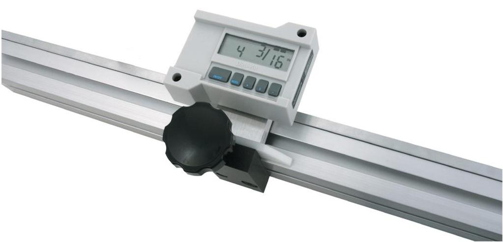
6 DigiStop Parts Each Digi-Stop is shipped in one or two packages (depending on the model). The first contains the Fence extrusion with the Scale attached. The second package (if necessary) contains the Digital Stop and installation hardware. Pictured below are parts that will be referred to throughout this manual. Scale Digital Readout Encoder Guide Clip Stop Readout Lock Knob Adjustable Wing Guide Clip Stop Encoder Digi- Stop End View Fence Manual Part # , Rev Page 6 of 16
 behind the first line (this is the centerline of the Fence). 4.")


7 SECTION 2 INSTALLATION Mounting the Fence Assembly 1. Align the Fence Assembly adjacent to the saw (Scale is to the rear of the fence). 2. Mark a line on the table top, along the front edge of the Fence. 3. Remove the Fence assembly and mark a second line 7/8 inch (22mm) behind the first line (this is the centerline of the Fence). 4. Drill mounting holes (at least 2) into the tabletop along the centerline of the Fence. 5. Insert the supplied 10mm bolts through the table from the top. Install the supplied hex nuts onto the bolts 1 or 2 threads deep at this time. 6. Slide the Fence, end first, back into place capturing the bolt heads in the bottom T-slot of the Fence Assembly. After the Fence is in place and aligned to the saw, tighten all nuts. Install Stop Assembly 1. Carefully slide the encoder onto the Scale. 2. Loosen the locking knob and slide the Stop assembly into the fence extrusion. 3. Position the encoder and Stop together and slide the encoder under the Guide Clip so the post on the encoder is captured in the slot of the Guide Clip, as shown below 4. Attach the readout to the aluminum block on the stop using the enclosed strips of Velcro. Plug the encoder into the readout. 5. Move the stop assembly left to right and note if the readings increase or decrease. Depending upon the installation (left or right infeed), it may be necessary to reverse the reading direction. See Section 3: Reverse Readings Accurate Technology DigiStop Page 7 of 16
 using the stop. DO NOT MOVE THE STOP UNTIL THIS PROCEDURE IS COMPLETED. 3.")
8 Calibration 1. Check to be sure installation of all parts is complete, all fasteners are secure and the Encoder is plugged into the Readout. 2. Cut a small part (approximately 8 inches) using the stop. DO NOT MOVE THE STOP UNTIL THIS PROCEDURE IS COMPLETED. 3. Measure the length of the part with the most precise measuring tool you have available (preferably digital calipers). 4. Press the Datum key to zero the readout, then press and hold the + (PLUS) key to change the reading until the length you just measured is shown (The longer the + key is held down, the faster the readout will scroll). This adjustment should be made in a decimal (inches or mm) mode for the best accuracy. 5. When the correct reading is reached, lock the readout if desired. This prevents accidentally re-zeroing during normal use. See Section 3: Readout Lock Mode Maintenance The fence extrusion should be cleaned of debris periodically. Do not use any liquid lubricants on the scale, as this may impede the encoder's ability to operate properly and attract other contaminants to the scale. If the stop becomes difficult to move, and the fence and scale have both been cleaned, the plastic wing may need adjustment: a. Position the wing to hold the locking mechanism of the stop in the center of the extrusion slot. b. The position of the wing can be adjusted after removing the plastic guide clip and loosening the socket screws (using a 3/16" hex wrench) which sandwich the wing between the stop and the aluminum block. The wing is adjusted properly when the weight of the stop is supported by the wing and the locking mechanism does not rub on the extrusion. The readout should be cleaned periodically with compressed air to remove any dust on the lens and keys. All fasteners should occasionally be checked for tightness. Manual Part # , Rev Page 8 of 16

9 Changing the Battery A low battery indicator will appear in the lower left corner of the LCD. When battery voltage drops below approximately 2.6V the readout will turn itself off until the battery is replaced. To replace the battery remove the screws in the upper right and lower left corners. Pull the cover off. Remove the old battery and install a new CR123 (or equivalent), noting the proper orientation. Replace the cover and tighten the screws. The LCD Display The above figure illustrates all the segments available on the LCD. (Not all segments are used on Digi-Stop Systems) Pressing and holding the ON/OFF and UNITS key for 10 seconds with power off will perform a full segment LCD test, display the current firmware version, and RESET ALL PROGRAMMING PARAMETERS TO FACTORY DEFAULTS. Accurate Technology DigiStop Page 9 of 16

10 SECTION 3 Readout Keys OPERATION Key Timing The keys pictured above, are found on all Digi-Stop readouts, and some of them have multiple functions. Timing, which is how long a key is depressed, and the combination of the keys pressed is important. This manual uses the term momentarily to describe a key press of shorter than 1 second. Whereas the term press and hold is used to describe a key press of longer than 1.5 seconds. As an example; when using a PC keyboard to type a capital letter you would press and hold the SHIFT key and momentarily depress the LETTER key. In addition most of the key functions are executed on RELEASE, not press. This is important since some of the same keys execute different functions based on how long they are pressed and when they are released. These key operations, once tried will quickly become intuitive. On/Off Momentarily pressing the ON/OFF key will cause the readout to turn on or off. The Firmware Version of the readout is displayed on power-up when ON/OFF key is used. While the readout is on, if the stop is not moved for 15 minutes, the readout will automatically turn itself off to conserve battery life. While it is off if the stop is moved as little as.002in (.05mm), or the ON/OFF button is pressed, the readout will automatically turn itself back on with no loss of position. Units The readout can display position information in decimal inches, fractions, or millimeters. To change the current display mode, momentarily press the UNITS key. With each key press the readout will cycle through decimal inches, fractional inches and millimeters. When the readout is in 1/16 or 1/32 inch fraction mode, a series of bars in the upper right corner of the display, each representing 1/64th of an inch, may appear. (ie. When in 1/16 inch mode and three bars are showing, the measurement displayed is rounded down to the closest 1/16 inch and each Manual Part # , Rev Page 10 of 16

11 illuminated bar indicates an additional 1/64 of an inch of measurement.) For better resolution, switch to 1/32 or 1/64 mode. For the best resolution and accuracy switch to a decimal mode inches or millimeters.. When the measurement is greater than 99 63/64 inches, a +100 and/or +200 will illuminate in the upper right portion of the display to indicate this amount must be added to the displayed reading. ie: If the measurement is 154 5/8 inches, 54 5/8 and +100 will be illuminated on the display. If the measurement is /64 inches, /64, +100 and +200 will be illuminated on the display. +, Datum, and - The + (plus), DATUM and (minus) keys are used to change the currently displayed position to a different value. The DATUM key forces the readout to display a user programmed value. Programming Parameter Pr1 Momentarily depressing the + key increments the current position by one unit of measurement. Momentarily depressing the key decrements the current position by one unit. Pressing and holding the + or keys will cause the displayed position to change continuously. Holding down the key will cause the amount of change to speed up. This allows for quick adjustments over a range of large values. NOTE: While the DATUM key can be used to simply zero the currently displayed value, it can also be programmed to force the readout to a preset value. This can be zero, or any other displayable value. See Section 3: Readout Programming, & Programming Parameter Pr1. Reverse Readings Reverse readings means changing the direction of readings produced by moving the stop. If the DigiStop decrements (reduces or goes negative) when it should be incrementing (increasing or going positive), the readout will need to be re-programmed for your installation (right vs left infeeds). See Section 3: Readout Programming & Programming Parameter Pr2. Accurate Technology DigiStop Page 11 of 16
12 Lock Mode To activate the Lock function Press and hold the ON/OFF key and then momentarily press the UNITS key. The word LOCK will appear in the upper left corner of the readout. When LOCK is displayed, the +, DATUM and keys become inactive to prevent accidental changes of the (calibrated) current displayed position. To de-activate the Lock function, press and hold the ON/OFF key and then momentarily press the UNITS key. NOTE: The Lock function can also be enabled/disabled through programming. This allows a more permanent Lock function since programming can be disabled with a hardware jumper inside the readout thus preventing any front panel programming changes. See Section 3: Readout Programming, Programming Parameter Pr3. Resolution The Digital readout can be configured to display measurements in any of three different resolutions. 1. Low the resolution is.1in or.1mm. 2. Normal the resolution is:.01in or.01mm. 3. High the resolution is:.001in or.01mm The display of fractions remains the same for all settings: 1/16, 1/32 & 1/64 See Section 3: Readout Programming &, Programming Parameter Pr4. Incremental Measurements The readout has two measurement modes, or indexes. One is referred to as ABS or Absolute, and the other as INC, or Incremental. The absolute measurement mode allows the operator to read the current position of the stop referenced from a fixed or known position such as the saw blade. The incremental mode allows the operator to make relative distance measurements from one arbitrary point to another. The absolute position of the Digi-Stop is not lost when using the incremental mode. Absolute The readout automatically enters ABS mode when power is first applied. This is indicated by the ABS symbol in the upper left corner of the display. While in the ABS mode, all stop positions are related to the current ABS, or absolute system reference point, ie the blade.. Incremental To enter the INC mode, press and hold the UNITS key for approximately 3 seconds. The INC symbol will appear in the upper left corner of the display. When the INC mode is entered the readout will display zero (0) or the last offset Manual Part # , Rev Page 12 of 16
.")
13 if one was entered, and may be changed by using the + or - keys to provide a different offset. Moving the stop in either direction will display the distance moved from the initial INC starting point (plus any offset). To complete another incremental measurement from the new position, momentarily press the UNITS key. The readout will again change to 0 (or the previously programmed offset). To return to the ABS mode, press and hold the UNITS key for approximately 3 seconds. NOTES: When the readout is in incremental measuring mode the UNITS key no longer functions to change the measurement units displayed. The absolute position of the Digi-Stop is not lost when using the incremental mode. When the readout is switched back to the absolute mode the readout reflests the current stop position relative to your original calibrated absolute setting. Circuit Board Jumpers The Digi-Stop readout has several user configurable jumpers consisting of three pins and a shorting block or jumper. The center of these three pins is Common. One end pin is labeled A and the other end pin is labeled B. JP1 JP2 JP1 JP2 FACTORY USE ONLY Programming Lockout Position A, Front Panel Programming is ENABLED Position B, Front Panel Programming is DISABLED Accurate Technology DigiStop Page 13 of 16
14 Readout Programming Several functions of the Digi-Stop readout is user programmable. The following describes what features and functions are available and how to change the factory defaults to customize your Digi-Stop system.. To enter Programming Mode: 1. Press and hold the UNITS key then momentarily press the DATUM key. 2. The LCD will briefly display: PG on (Programming On), then Pr 1, (indicating Programming Parameter #1) 3. Release the UNITS key 4. The value stored in Pr1 is displayed. Press & Hold Momentarily Once in the Programming Mode: Moving up parameter list - Momentarily press the UNITS key to advance through the Programming Parameter list, first displaying the Programming Parameter number then the currently programmed value. Moving down parameter list - Press and hold the ON/OFF key and momentarily press the UNITS key to move backward through the Programming list. Increase parameter value - Momentarily press the PLUS (+) key while displaying a Programming Parameter Value to increase the setting. Decrease parameter value - Momentarily press the MINUS (-) key while displaying a Programming Parameter Value to decrease the setting. Reset parameter value to default setting - Momentarily press the DATUM key while displaying a Programming Parameter Value to reset the parameter to the factory default value. Exit programming mode - Press and hold the UNITS key. Momentarily depress the DATUM key. The LCD will briefly display: PG off (Programming Off), then return to normal operation. NOTE: The system will automatically exit programming mode after 60 seconds of no key activity. Manual Part # , Rev Page 14 of 16
15 Programming Parameters The Digi-Stop readout programming parameters are listed below. Values in [ ] are the available range of values that can be entered for that parameter. Factory defaults are shown in Bold Red. Pr 1 Datum Key [0 to in] or [0 to mm] The programmed value that will be recalled whenever the DATUM key is pressed during normal operation. Default = 0.00 Pr 2 Reverse Readings [0 or 1] This parameter controls the direction of travel (positive vs. negative) when the stop is moved. Default = 0 Pr 3 Key Lockout [0 or 1] This parameter controls the operation of the +, - and DATUM keys. If enabled, (set to 1), these keys will not function and the LOCK symbol will appear on the display. This prevents accidental changes when pressing these keys during normal operation. Default = 0 Pr 4 Readout Resolution [1, 2, 3 ] This parameter sets the number of places to the right of the decimal point on the readout. Default = 2 A value of 1 Low - will display x.x. A value of 2 Normal -will display x.xx A value of 3 High - will display x.xxx Frequently Asked Questions What F/W (Firmware) version do I have? The readout will display the firmware version on power up. What does no Enc mean? If the encoder cable is unplugged from the readout, no Enc will appear on the display. To clear: Be sure the encoder is on the scale and plugged into the readout. The readings are backwards? You can change reading direction of the Digi-Stop by changing the value of Programming Parameter Pr 2. What does b FAIL mean? When the readout displays this message it means the battery voltage has dropped to a level where reliable operation is no longer possible. Install new batteries to clear this message. What does P FAIL mean? When the readout displays this message it means the battery voltage has dropped to a level where reliable programming is not possible. Install new batteries to clear this message. Accurate Technology DigiStop Page 15 of 16


16 Thank you for choosing an AMERICAN MADE PRODUCT Accurate Technology, Inc. 270 Rutledge Rd. Unit E Fletcher, NC USA Please register your product at: This manual is available online at: Manual P/N Rev Copyright Accurate Technology 2014 Manual Part # , Rev Page 16 of 16
Digi-Stop. User Manual for: Digi-Stop. Digital Readout Firmware version d & Higher
 Digi-Stop User Manual for: Digi-Stop Digital Readout Firmware version d 2.000 & Higher Warranty Accurate Technology, Inc., warrants this product against defective parts and workmanship for 1 year commencing
Firmware Version d & higher Installation & Operation
 DIGI LCD Readout Firmware Version d 2.100 & higher Installation & Operation Warranty Accurate Technology, Inc., warrants this product against defective parts and workmanship for 1 year commencing from
Digi-Fence. User Manual for: Digi-Fence (all models) Digital Readout Firmware version d & Higher
 Digital Readout Firmware version d & Higher") Digi-Fence User Manual for: Digi-Fence (all models) Digital Readout Firmware version d 2.000 & Higher Warranty Accurate Technology, Inc., warrants this product against defective parts and workmanship for
Digi-Fence User Manual for: Digi-Fence (all models) Digital Readout Firmware version d 2.000 & Higher Warranty Accurate Technology, Inc., warrants this product against defective parts and workmanship for
Digi-Fence. User Manual (all models) For All Models with Digital Readout Firmware version d & Higher
 For All Models with Digital Readout Firmware version d & Higher") Digi-Fence User Manual (all models) For All Models with Digital Readout Firmware version d 2.000 & Higher Warranty Accurate Technology, Inc., warrants this product against defective parts and workmanship
Digi-Fence User Manual (all models) For All Models with Digital Readout Firmware version d 2.000 & Higher Warranty Accurate Technology, Inc., warrants this product against defective parts and workmanship
Firmware Version d & higher Installation & Operation
 DIGI LCD Readout Firmware Version d 2.100 & higher Installation & Operation READOUT SERIAL # SCALE SERIAL # TO MAXIMIZE THE ACCURACY OF YOUR SYSTEM, THE FOLLOWING PROGRAMMING PARAMETER HAS BEEN PRE-CONFIGURED
ProScale Compact LCD Readout. Operation. Firmware version C 2.xxx and higher
 ProScale Compact LCD Readout Operation Firmware version C 2.xxx and higher WARRANTY Accurate Technology, Inc., warrants this product against defective parts and workmanship for 1 year commencing from the
ProScale. Compact LCD Readout. Installation & Operation
 ProScale Compact LCD Readout Installation & Operation WARRANTY Accurate Technology, Inc. warrants the ProScale Measurement Systems against defective parts and workmanship for 1 year commencing from the
Putsch Meniconi Vertical Scale Instructions
 Putsch Meniconi Vertical Scale Instructions Please note this installation kit is designed solely for installation on Putsch Meniconi Vertical Panel Saws, vertical measurement. Accurate Technology manufactures
Holz-Her Sliding Table Saw Kit Installation Instructions: For 1243 Cross-Cut Kits 2 DRO Retrofit
 Holz-Her Sliding Table Saw Kit Installation Instructions: For 1243 Cross-Cut Kits 2 DRO Retrofit Please note this installation kit is designed solely for installation on Holz-Her Sliding Panel Saws, Model
Elcon Vertical Panel Saw Kit Installation Instructions: For Vertical Scale, Horizontal Cuts
 Elcon Vertical Panel Saw Kit Installation Instructions: For Vertical Scale, Horizontal Cuts Please note this installation kit is designed solely for installation on Elcon DSX 155 Vertical Panel Saws. Accurate
SCMI Cross Cut Kit Installation Instructions
 SCMI Cross Cut Kit Installation Instructions Please note this installation kit is designed for installation on SCMI Sliding Table Saws (models SI12,SI16, SI16N, Hydro 3200, 300 Nova), Cross-Cut fences.
Transmitter. User Manual. Firmware version 1.0 and greater
 ProRF SPC Transmitter User Manual Firmware version 1.0 and greater FCC NOTICE This equipment has been tested and found to comply with the limits for a class B digital device, pursuant to part 15 of the
User Manual. ProRF Encoder Transmitter & Receiver
 User Manual ProRF Encoder Transmitter & Receiver WARRANTY Accurate Technology, Inc. warrants the ProScale Systems against defective parts and workmanship for 1 year commencing from the date of original
ProPanel HD E SERIAL # OPERATION
 ProPanel HD E SERIAL # OPERATION WARRANTY Accurate Technology, Inc. warrants the ProScale Systems against defective parts and workmanship for 1 year commencing from the date of original purchase. Upon
SawStop. Contractor Fence Assembly OWNER S MANUAL. Model CNS-SFA
 Contractor Fence Assembly OWNER S MANUAL Model CNS-SFA Warranty warrants to the original retail purchaser of the Contractor Fence Assembly accompanying this manual that the fence assembly will be free
Instruction Sheet D-CPU. Secure CPU Holder
 Instruction Sheet D-CPU Secure CPU Holder I-00457 Rev A PARTS LIST NOTE: Select Security Components when a more secure application is desired. Mounting Track with Mounting Tape Security Bracket Assembly
Fletcher F-3000 / F-3100 Accessory Laser Kit
 Fletcher F-3000 / F-3100 Accessory Laser Kit Shown Assembled on F-3000 Machine Product Warranty The Fletcher-Terry Company warrants the product purchased to be free from defects in parts and workmanship
OPERATOR S MANUAL Model 77E Pneumatic Cable Stripper
 110 Fairgrounds Drive P.O. Box 188 Manlius, NY 13104-0188 USA 315.682.9176 FAX: 315.682.9160 OPERATOR S MANUAL Model 77E Pneumatic Cable Stripper PRODUCTION WIRE PROCESSING EQUIPMENT Website: www.carpentermfg.com
Assembly Instructions and Parts Manual JPSF-1 Fence and JPSR Rail Set
 Assembly Instructions and Parts Manual JPSF-1 Fence and JPSR Rail Set WALTER MEIER (Manufacturing) Inc. 427 New Sanford Road LaVergne, Tennessee 37086 Part No. M-708482 Ph.: 800-274-6848 Revision C2 02/2013
LC200WT Security Wall Mount with Tilt for up to 32" Flat Screens
 Page 1 of 6 The LC200WT Security Wall Mount with Tilt is designed to secure up to a 32" flat panel monitor to the wall while still allowing the monitor to tilt. The VESA mounting patterns on the front
Assembly Instructions and Parts Manual JPSF-1 Fence and JPSR Rail Set #
 Assembly Instructions and Parts Manual JPSF-1 Fence and JPSR Rail Set #1002493 JET 427 New Sanford Road LaVergne, Tennessee 37086 Part No. M-708482 Ph.: 800-274-6848 Revision C3 02/2014 www.jettools.com
LC6X4WTM Security Wall Mount with Tilt for up to 60" Flat Screens with VESA 600mm x 400mm or less
 Page 1 of 6 The LC6X4WTM Security Wall Mount with Tilt is designed to secure a flat screen, up to a 60", to the wall while still allowing the monitor to tilt. The VESA mounting patterns on the front of
Biesemeyer fi T-Square fi Commercial Fence Systems 50 Capacity (Model ) 30 Capacity (Model ) INSTRUCTION MANUAL
 30 Capacity (Model ) INSTRUCTION MANUAL") iesemeyer fi T-Square fi Commercial Fence Systems 50 Capacity (Model 78-904) 30 Capacity (Model 78-907) INSTRUCTION MNUL D T E D 3-5-96 P RT NO. 1349984 'Delta International Machinery Corp. 1996 INTRODUCTION
iesemeyer fi T-Square fi Commercial Fence Systems 50 Capacity (Model 78-904) 30 Capacity (Model 78-907) INSTRUCTION MNUL D T E D 3-5-96 P RT NO. 1349984 'Delta International Machinery Corp. 1996 INTRODUCTION
LC200DS1 Double Stud Articulating Wall Mount for Flat Panel Screens up to 32" with up to 200mm x 200mm VESA Mounting Patterns
 Page 1 of 6 LC200DS1 Double Stud Articulating Wall Mount for Flat Panel Screens up to 32" with up to 200mm x 200mm VESA Mounting Patterns A multi-position dual articulating arm for flat screens up to 60
OPERATOR S MANUAL Model 58B Prefeed / Dereeler
 110 Fairgrounds Drive P.O. Box 188 Manlius, NY 13104-0188 USA 315.682.9176 FAX: 315.682.9160 OPERATOR S MANUAL Model 58B Prefeed / Dereeler PRODUCTION WIRE PROCESSING EQUIPMENT Website: www.carpentermfg.com
Owner s Manual & Safety Instructions
 Owner s Manual & Safety Instructions Save This Manual Keep this manual for the safety warnings and precautions, assembly, operating, inspection, maintenance and cleaning procedures. Write the product s
Installation Instructions Hinged Roof Rack
 Installation Instructions Hinged Roof Rack Application: Jeep Wrangler Unlimited 2004 - Current Part Number: 41435-01 www.bestop.com - We re here to help! Visit our web site and click on Ask a Question
OWNER S MANUAL. Safety. Please read this owner s manual before use and keep it at hand for reference. Warranty
 Please read this owner s manual before use and keep it at hand for reference. OWNER S MANUAL Safety Important safety instructions for using the INCRA Miter5000 Before using the INCRA Miter5000, read and
EBONITE MILL DRILL OPERATIONS MANUAL
 EBONITE MILL DRILL OPERATIONS MANUAL REV A 12-2-05 1 EBONITE MILL DRILL OPERATIONS MANUAL Table of Contents Mill Drill Set-Up Section (1) Receiving New Machine 3 Section (2) Locating New Machine 3 Section
Fletcher-Terry Titan Series Rotary Trimmers
 Fletcher-Terry Titan Series Rotary Trimmers Instruction Manual Provided By http://www.mybinding.com http://www.mybindingblog.com OWNER S MANUAL Fletcher Titan The Fletcher-Terry Company 65 Spring Lane
SawStop. T-GlideTM. Fence System- Professional Series II OWNER S MANUAL
 SawStop T-GlideTM Fence System- Professional Series II OWNER S MANUAL Warranty SawStop warrants to the original retail purchaser of a new T-Glide Fence System - Professional Series II from an authorized
COMPETITOR CB-610 STANDARD BENCH
 NOTE: Please read all instructions carefully before using this product Table of Contents Safety Notice COMPETITOR CB-610 STANDARD BENCH Hardware Identifier Assembly Instruction Exploded Diagram Parts List
User Manual. Where Imagination Meets Innovation. FRESH AERO Easy Seat Tool For Grumman AA1 & AA5 Series Aircraft
 FRESH AERO Easy Seat Tool For Grumman AA1 & AA5 Series Aircraft Alpha Model For Grumman AA-1 & AA-5 Series Aircraft with Access Holes in Front Seat Buckets User Manual The Steelebrook Group Where Imagination
!ATTENTION: READ BEFORE ASSEMBLING/OPERATING! ASSEMBLY & PACKING INSTRUCTIONS FOR THE MULTICHAIR 4000tx
 !ATTENTION: READ BEFORE ASSEMBLING/OPERATING! ASSEMBLY & PACKING INSTRUCTIONS FOR THE MULTICHAIR 4000tx multichair 4000Tx!ATTENTION: READ BEFORE ASSEMBLING/OPERATING! November 2016 ASSEMBLY INSTRUCTIONS!ATTENTION:
th St N Oak Park Heights, MN Phone: Fax:
 12430 55 th St N Oak Park Heights, MN 55082 Phone: 651.342.1756 Fax: 651.342.1293 Email: info@diacro.com SAFETY INFORMATION PG. 3 MAINTENANCE PG. 3 #4 BENDER BREAKDOWN AND PARTS LIST PG. 4-6 QUIK-LOK BREAKDOWN
OWNER'S MANUAL JST-48 Sliding Table
 OWNER'S MANUAL JST-48 Sliding Table (shown mounted on JET 708663PK) JET EQUIPMENT & TOOLS, INC. P.O. BOX 1349 Phone:253-351-6000 A WMH Company Auburn, WA 98071-1349 Fax: 1-800-274-6840 www.jettools.com
STRINGING MACHINE OWNER'S MANUAL. Copyright 1998 GAMMA Sports - All Rights Reserved
 6002 STRINGING MACHINE OWNER'S MANUAL Issue 3 - June 20, 1998 Copyright 1998 GAMMA Sports - All Rights Reserved 6002 OWNER'S MANUAL TABLE OF CONTENTS PAGE 1... WARRANTY PAGE 2... FEATURES PAGE 3... ASSEMBLY
Installation Instructions Lower Cargo Rack Bracket
 Installation Instructions Lower Cargo Rack Application: Jeep Wrangler 2003 Current Part Number: 41437 US Patent 6799706 www.bestop.com - We re here to help! Visit our web site and click on Ask a Question.
Model 72D Twin Blade Rotary Wire Stripper
 110 Fairgrounds Drive P.O. Box 188 Manlius, NY 13104-0188 USA 315.682.9176 FAX: 315.682.9160 OPERATOR S MANUAL Model 72D Twin Blade Rotary Wire Stripper PRODUCTION WIRE PROCESSING EQUIPMENT Website: www.carpentermfg.com
Installation Instructions BestRail Ladder Rack Must be used with BestRail Accessories: Overhead Rack
 Installation Instructions BestRail Ladder Rack Must be used with Accessories: 42791 Can be used with Accessories: 42793 Tie Down 42794 Retractable Tie Down The channels in the Ladder Rack are the same
Record the serial number and date of purchase in your manual for future reference.
 10 Woodworking Bandsaw Model: 10-305 Parts List Record the serial number and date of purchase in your manual for future reference. Serial number: Date of purchase: Part # 10-305PL1 For more information:
Planishing hammer stand For use with SKU Planishing hammer
 Planishing hammer stand For use with SKU 94847 Planishing hammer Model 96300 Assembly And Operation Instructions Please Note: Planishing Hammer not included with Stand. Due to continuing improvements,
Hinge Boring/Insertion Machine Set Up And Operation Instructions
 Hinge Boring/Insertion Machine Set Up And Operation Instructions Manufactured In The USA By: Thompson Industries, Inc. 1018 Crosby Avenue, Sycamore, IL. 60178-0127 Ph:815-899-6670 Fax:815-899-1918 Thank
Owner s Manual ODYSSEY BENCH MODEL. O4100B shown REV E. Southern Avenue, Phoenix, AZ USA Workhorseproducts.
 Owner s Manual ODYSSEY BENCH MODEL O4100B shown 67-1375 REV 218 3730 E. Southern Avenue, Phoenix, AZ 85040 USA 800-778-8779 Workhorseproducts.com 1 Table of Contents I. Introduction & Safety Information.
Tilting, Swiveling & Rotating Flat Panel Wall Mount
 Tilting, Swiveling & Rotating Flat Panel Wall Mount Model: VXA980TC +5 to -5 +5 to -5 Supports most 0-80 Flat Panel TVs Maximum Weight Capacity: 32 lbs. Supports VESA Sizes up to 600x500 For technical
9 PIECE TUNGSTEN CARBIDE HOLE SAW KIT. Model 90721
 9 PIECE TUNGSTEN CARBIDE HOLE SAW KIT Model 90721 Set up And Operating Instructions Diagrams within this manual may not be drawn proportionally. Due to continuing improvements, actual product may differ
ALUMA-CLASSIC FENCE W1716 & W1720 INSTRUCTION MANUAL
 ALUMA-CLASSIC FENCE W1716 & W1720 INSTRUCTION MANUAL Phone: Phone: 1-360-734-3482 On-Line On-Line Technical Technical Support: Support: tech-support@woodstockint.com tech-support@shopfox.biz COPYRIGHT
V-Groover SIMPLEX INSTRUCTION AND OPERATION MANUAL M O DEL 703. For best results use only authentic Logan blades.
 www.logangraphic.com SIMPLEX M O DEL 703 INSTRUCTION AND OPERATION MANUAL For best results use only authentic Logan blades CAUTION: BLADES EXTREMELY SHARP Use replacement blades #1258 Logan Graphic Products,
Installation Instructions Tailgate Rack Bracket
 Installation Instructions Tailgate Rack Application: Jeep Wrangler 1986 Current Part Number: 41411 www.bestop.com - We re here to help! Visit our web site and click on Ask a Question. Click here for more
Installation and Assembly: Articulating Swivel Arm for 37" - 60" Flat Panel Displays
 Installation and Assembly: Articulating Swivel Arm for 37" - 60" Flat Panel Displays Models: PLA60, PLA60-S, PLAV60, PLAV60-S Max UL Load Capacity: 175 lb (79 kg) 2300 White Oak Circle Aurora, Il 60502
Tilting & Swiveling Plasma/LCD Flat Panel Wall Mount Installation Guide Model: A380SM
 Tilting & Swiveling Plasma/LCD Flat Panel Wall Mount Installation Guide Model: A380SM Easy installation Built-in level for easy positioning Corrective leveling adjustments after installation Forward /
MODEL T28000 HEAVY-DUTY MOBILE BASE INSTRUCTIONS
 MODEL T28000 HEAVY-DUTY MOBILE BASE INSTRUCTIONS For questions or help with this product contact Tech Support at (570) 546-9663 or techsupport@grizzly.com Introduction Your new Model T28000 Heavy-Duty
LC200DS2 Double Stud Dual Articulating Wall Mount for Flat Panel Screens up to 32" with up to 200mm x 200mm VESA Mounting Patterns
 LC200DS2 Double Stud Dual Articulating Wall Mount for Flat Panel Screens up to 32" with up to 200mm x 200mm VESA Mounting Patterns Multi-position triple pivoting arms allows you to position the monitor
M ACS Instructions
 APPLICABLE MODELS: Nissan Frontier 2005 and up short bed with Utili-Trak mounting rails PACKAGE CONTENTS 00-0060-M-01-1205 ACS Instructions Leitner Designs 25675 Taladro Circle Unit E Mission Viejo, CA
Installation Instructions HOSS Hardtop Organized Storage System
 Installation Instructions HOSS Hardtop Organized Storage System Application: Hard Top and Doors Storage System Part Number: 42801 www.bestop.com - We re here to help! Visit our web site and click on Ask
DRO 200T REFERENCE MANUAL
 DRO 200T REFERENCE MANUAL Readout Parameter Access Code An access code must be entered before machine-related parameters can be set or changed. This prevents inadvertent adjustments to the setup parameters.
Specifications. Important Safety Information
 Specifications Tire Rim Capacity 4 to 12 Rim Height 16 (2) Bead Breaker Handles 21 Long Includes Aluminum Centering Cone (2) Nylon Spacers Important Safety Information 1. Do not exceed max. tire capacity.
Loading Dock Safety Gate
 Installation Instructions/Operation and Maintenance Manual Models LDSG-120-PCY LDSG-144-PCY Table of Contents Product Information...2 Parts List...3 Installation Instructions...5 Operation...13 Inspection
Owner s Manual AE PLUG AERATOR MANUFACTURING QUALITY LAWN CARE EQUIPMENT SINCE Made In CHINA REV
 MANUFACTURING QUALITY LAWN CARE EQUIPMENT SINCE 1945 Owner s Manual AE-48 48 PLUG AERATOR IMPORTANT Read and follow all Safety Precautions and Instructions Before Operating this Equipment. Made In CHINA
Owner s Manual GS2010 Garden Seeder/Fertilizer. Caution: Carefully read all Rules and Instructions for Safe Operation.
 Manufacture s Limited Warranty for The limited warranty set forth below is given by Precision Products, Incorporated with respect to new merchandise purchased and used in the United States, its possessions
HUSTLER 7' & 8' POOL TABLE ASSEMBLY INSTRUCTIONS
 HUSTLER 7' & 8' POOL TABLE ASSEMBLY INSTRUCTIONS Please Do Not Hesitate to Contact Our Consumer Hotline at 800-759-0977 with Any Questions That May Arise During Assembly or Use of This Product! NG2515PB/NG2520PB
Sea Doo Spark Engine Access Kit
 Sea Doo Spark Engine Access Kit PART# - RS4-130-EAK APPLICATION(S): Sea Doo Spark. 2up & 3up Models. We strongly recommend the use of a service manual to familiarize yourself with the various components
HARDINGE Installation booklet For: Dead-Length Collet Adaptation Chucks Stationary Collet
 HARDINGE Installation booklet For: Dead-Length Collet Adaptation Chucks Stationary Collet Read the enclosed instructions and recommendations before any installations CONTENTS Dead-Length Collet Adaptation
Miter Saw Super Stand
 Quality Power Tool Accessories OWNER S MANUAL Miter Saw Super Stand Models 2875/2875XL IMPORTANT Read and understand all safety guidelines and instructions carefully before operating. GENERAL INFORMATION
Owner s Manual LSP38 38 Lawn Sweeper
 Owner s Manual LSP38 38 Lawn Sweeper Manual Contents Safety Instructions Assembly Operation Maintenance Parts Warranty 2 4-13 2 11 14-15 16 Your Lawn Sweeper Congratulations on your purchase of a new Precision
AUTOMATION. Operator s Manual. IRU-2xx4/3xx4 Series. Rev. A2, 11/08 Doc
 AUTOMATION P R O D U C T S G R O U P, I N C. Operator s Manual IRU-2xx4/3xx4 Series Rev. A2, 11/08 Doc. 9002673 Tel: 1/888/525-7300 Fax: 1/435/753-7490 www.apgsensors.com E-mail: sales@apgsensors.com IRU-2xx4/3xx4
MODEL M1023 QUICK CHANGE COLLET ATTACHMENT INSTRUCTION MANUAL. Phone: On-Line Technical Support:
 MODEL M1023 QUICK CHANGE COLLET ATTACHMENT INSTRUCTION MANUAL Phone: 1-360-734-3482 On-Line Technical Support: tech-support@shopfox.biz #6727BL COPYRIGHT JANUARY, 2005 BY WOODSTOCK INTERNATIONAL, INC.
ALL RIGHTS RESERVED BY KING CANADA TOOLS INC.
 INDUSTRIAL RIP FENCE SYSTEM MODELS KRF-10/30L12-30 CONTRACTOR SAWS KRF-10/52L12-52 CONTRACTOR SAWS KRF-100/T50L12-50 CABINET SAWS INSTRUCTION MANUAL COPYRIGHT C 2000 ALL RIGHTS RESERVED BY KING CANADA
Installation Instructions TrekStep Side Mount
 Installation Instructions TrekStep Side Mount Vehicle Application Chevrolet Silverado / GMC Sierra All Bed Sizes 1999 Current Part Number: 75400-15 www.bestop.com - We re here to help! Visit our web site
SERIES M MIXER MASTS
 SERIES M MIXER MASTS T AB L E O F C O N T E N T S V e n d o r D a t a Material Data Sheet 4-in. Mixer Mast Specification 3-in. Mixer Mast Specification 2 - in. M i x e r M a s t S p e c i f i c a t i o
Guitar Mobile Storage Rack
 Assembly Instructions Guitar Mobile Storage Rack CONTENTS Safety Precautions.................................. 2 Warranty.......................................... 2 Operation.........................................
INSTRUCTION MANUAL TAPER ATTACHMENT MODEL M1022. Phone: (360) On-Line Technical Support: FOR USE WITH MODEL M1019
 On-Line Technical Support: FOR USE WITH MODEL M1019") MODEL M1022 TAPER ATTACHMENT FOR USE WITH MODEL M1019 INSTRUCTION MANUAL Phone: (360) 734-3482 On-Line Technical Support: tech-support@shopfox.biz #6809BL COPYRIGHT DECEMBER, 2004 BY WOODSTOCK INTERNATIONAL,
MODEL M1022 TAPER ATTACHMENT FOR USE WITH MODEL M1019 INSTRUCTION MANUAL Phone: (360) 734-3482 On-Line Technical Support: tech-support@shopfox.biz #6809BL COPYRIGHT DECEMBER, 2004 BY WOODSTOCK INTERNATIONAL,
Installation Instructions HighRock 4x4 TM
 Installation Instructions HighRock 4x4 TM Slider Step Vehicle Application: Jeep CJ Wrangler 1976 1986 Part Number: 49311 www.bestop.com - We re here to help! Visit our web site and click on Ask a Question.
RPR-265. Power Rack (Cage)
") ASSEMBLY INSTRUCTIONS 3 3/4" RPR-5 50 3/4" 51 1/4" Power Rack (Cage) TuffStuff Fitness Equipment, Inc. 15 E. Franklin Avenue Pomona, CA 9166, USA Ph: 909-6-1600 Fax: 909-6-496 E-mail: service@tuffstuff.net
ASSEMBLY INSTRUCTIONS 3 3/4" RPR-5 50 3/4" 51 1/4" Power Rack (Cage) TuffStuff Fitness Equipment, Inc. 15 E. Franklin Avenue Pomona, CA 9166, USA Ph: 909-6-1600 Fax: 909-6-496 E-mail: service@tuffstuff.net
Sunset Swings By Health in Motion, LLC
 Sunset Swings By Health in Motion, LLC Model 421 Lounge Swing Assembly and Operation Manual Record Serial Number Here www.sunsetswings.com by Health In Motion, LLC. 11/6/2009 421 Owners Assembly and Operation
TABLE OF CONTENTS WARRANTY
 DM4000 CONTROL SERIES CONTROLS Instruction Manual Field Programmable Digital Tachometer for Rate and Time P.O. Box 10 5000 W. 106th Street Zionsville, Indiana 46077 Phone (317) 873-5211 Fax (317) 873-1105
!ATTENTION: READ BEFORE ASSEMBLING/OPERATING! ASSEMBLY INSTRUCTIONS FOR THE MULTICHAIR 6000Tilt Series
 !ATTENTION: READ BEFORE ASSEMBLING/OPERATING! ASSEMBLY INSTRUCTIONS FOR THE MULTICHAIR 6000Tilt Series multichair 6000Tilt multichair 6200Tilt multichair 6000Tilt P1 multichair 6000Tilt P2!ATTENTION: READ
Model 6360/6361. Ambulance Cot Fastener INSTALLATION/OPERATION INSTRUCTIONS. IMPORTANT Keep manual on file at all times.
 IMPORTANT Keep manual on file at all times. Model 6360/6361 Ambulance Cot Fastener INSTALLATION/OPERATION INSTRUCTIONS For Parts or Technical Assistance 1 800 784 4336 Table of Contents Introduction..............................................................................
Signature Choral Riser Side Rail
 Assembly/Owner s Manual Signature Choral Riser Side Rail Signature Choral 3-Step Riser with Optional Side Rail Signature Choral 4-Step Riser with Optional Side Rail CONTENTS Visit the Signature Choral
9 QUICK RELEASE WOODWORKING VISE
 9 QUICK RELEASE WOODWORKING VISE 94386 OPERATING INSTRUCTIONS Due to continuing improvements, actual product may differ slightly from the product described herein. 349 Mission Oaks Blvd., Camarillo, CA
Installation Instructions TrekStep Side Mount
 Installation Instructions TrekStep Side Mount Vehicle Application Ford F150 Regular Cab and Super Cab 2009 Current Part Number: 75402-15 Fits both Driver s and Passenger Side www.bestop.com - We re here
User Manual. Flooring Removal Machine (Patent Pending) Maintenance and Operating Instructions
 Maintenance and Operating Instructions") User Manual Flooring Removal Machine (Patent Pending) Maintenance and Operating Instructions Copyright 2012 by Carpet Concepts LLC. All Rights Reserved. For technical questions or replacement parts please
User Manual Flooring Removal Machine (Patent Pending) Maintenance and Operating Instructions Copyright 2012 by Carpet Concepts LLC. All Rights Reserved. For technical questions or replacement parts please
DRO 100 REFERENCE MANUAL
 DRO 100 REFERENCE MANUAL Warranty ACU-RITE Products and accessories are warranted against defects in material and workmanship for a period of three years from the date of purchase. ACU-RITE will, at its
Tablet Arm for Wenger Playright Chairs
 Assembly Instructions Tablet Arm for Wenger Playright Chairs CONTeNTs Before You Begin..........................................................2 Warranty.................................................................2
OWNER'S MANUAL. Please Do Not Return This Product To The Store!
 MODEL NO. T8190SA TABLE TENNIS TABLE OWNER'S MANUAL 1. Read this manual carefully before starting assembly. Read each step completely before beginning each step.. Some smaller parts may be shipped inside
Installation Instructions Factory Style Bow Kit
 INSTALLATION TIME Installation Instructions Factory Style Bow Kit SKILL LEVEL Vehicle Application: Jeep Wrangler JK 2 Door 2007 Current Part Number: 55000 Compatible with original equipment soft tops,
!ATTENTION: READ BEFORE ASSEMBLING/OPERATING! ASSEMBLY & PACKING INSTRUCTIONS FOR THE MULTICHAIR 6000 Series
 !ATTENTION: READ BEFORE ASSEMBLING/OPERATING! ASSEMBLY & PACKING INSTRUCTIONS FOR THE MULTICHAIR 6000 Series multichair 6000 multichair 6200!ATTENTION: READ BEFORE ASSEMBLING/OPERATING! November 2016 ASSEMBLY
COMPETITOR WM-203 COMBO BENCH
 NOTE: Please read all instructions carefully before using this product Table of Contents Safety Notice Hardware Identifier COMPETITOR WM-203 COMBO BENCH Assembly Instruction Exploded Diagram Parts List
INSTALLATION MANUAL SONANCE SOUNDBARS SB46 M AND SB46 L. Introduction. Box Contents. Wall Mount Installations
 INSTALLATION MANUAL SONANCE SOUNDBARS SB46 M AND SB46 L Introduction Thank you for purchasing the Sonance Soundbar SB46 M or SB46 L. When properly installed your new Soundbar will give you years of entertainment
Model DB Disc Caliper Brake AIR CHAMP PRODUCTS. User Manual. (i) MTY (81)
 MTY (81)") DIST. AUTORIZADO MEX (55) 53 63 3 3 QRO (44) 95 7 60 MTY (8) 83 54 0 8 AIR CHAMP PRODUCTS User Manual Model DB Disc Caliper Brake (i) FORM NO. L-00-G-030 MEX (55) 53 63 3 3 MTY (8) 83 54 0 8 DIST. AUTORIZADO
DIST. AUTORIZADO MEX (55) 53 63 3 3 QRO (44) 95 7 60 MTY (8) 83 54 0 8 AIR CHAMP PRODUCTS User Manual Model DB Disc Caliper Brake (i) FORM NO. L-00-G-030 MEX (55) 53 63 3 3 MTY (8) 83 54 0 8 DIST. AUTORIZADO
INSTALLATION INSTRUCTIONS
 INSTALLATION INSTRUCTIONS BRONCO FAST TRAC TOP PART #331-210 BRONCO 1966-1977 Thank you for purchasing Specialty s Convertible Top for your Bronco. It has been designed for great fit and long wear. Please
model tsa-sa48 Sliding Crosscut Table installation guide
 model tsa-sa48 Sliding Crosscut Table installation guide A Note About Color Variations Among Anodized Aluminum Components Congratulations on the purchase of this SawStop Sliding Crosscut Table. We at SawStop
2015 RIGOL TECHNOLOGIES, INC.
 Service Guide DG000 Series Dual-channel Function/Arbitrary Waveform Generator Oct. 205 TECHNOLOGIES, INC. Guaranty and Declaration Copyright 203 TECHNOLOGIES, INC. All Rights Reserved. Trademark Information
ASSEMBLY INSTRUCTIONS Last Updated
 ASSEMBLY INSTRUCTIONS Last Updated 05.08.08 5 & 10 Row Bleacher Instructions for all bleacher lengths. Guardrail and toe board installation included. 90653 9 Long 5 Row Bleacher 90654 15 Long 5 Row Bleacher
!ATTENTION: READ BEFORE ASSEMBLING/OPERATING! ASSEMBLY INSTRUCTIONS FOR THE NUPRODX MULTICHAIR 6000RS
 !ATTENTION: READ BEFORE ASSEMBLING/OPERATING! ASSEMBLY INSTRUCTIONS FOR THE NUPRODX MULTICHAIR 6000RS November 2016 1 !ATTENTION: PLEASE READ! Please see LIMITED WARRANTY on the last page of these instructions.
INSTALLATION INSTRUCTIONS Scout II - Fast Trac PART #
 INSTALLATION INSTRUCTIONS Scout II - Fast Trac PART #442-210 Thank you for purchasing Specialty s Convertible Top for your Scout vehicle. It has been designed for great fit and long wear. Please read and
1260 Automatic Traverse
 Adams-Maxwell Winding Systems Operating Manual 1260 Automatic Traverse Page 2 Adams-Maxwell 4740 Calle Carga Camarillo, CA 93012 Phone: (323) 936-8028 Fax: (888) 936-8042 Web: www.adamsmaxwell.com Email:
MARCY CLASSIC MCB-252 COMBO BENCH W/120 lbs Weight Set
 NOTE: Please read all instructions carefully before using this product Table of Contents Safety Notice Hardware Identifier Assembly Instruction MARCY CLASSIC MCB-252 COMBO BENCH W/120 lbs Weight Set Exploded
OWNER S MANUAL. But that s just half the story. The fence INCRA Miter Gauge really does work
 From the makers of the INCRA JIG! Please read this owner s manual before use and keep it at hand for reference. Your new INCRA Miter Gauge at long last solves that frustrating problem all too familiar
INSTRUCTION MANUAL. Lathe Duplicator MODEL North Glenn Road, Casper, Wyoming woodworker.com
 140-069LatheDuplictr(1/12) 10/30/06 8:20 AM Page 1 INSTRUCTION MANUAL Lathe Duplicator MODEL 140-069 1108 North Glenn Road, Casper, Wyoming 82601 1-800-645-9292 woodworker.com 140-069LatheDuplictr(1/12)