Grounding and Utility Enclosure
|
|
|
- Osborne Hubbard
- 5 years ago
- Views:
Transcription

 572-3200 Fax: (330) 572-3279 E-mail:")
1 Grounding and Utility Enclosure DXE-UE-2P DXE-UE-2P-INS Rev 1f DX Engineering Southeast Ave. - Tallmadge, OH USA Phone: (800) Tech Support and International: (330) Fax: (330) DXEngineering@DXEngineering.com - 1 -

2 Introduction The DXE-UE-2P is a weather-resistant, high impact thermoplastic enclosure which is ideal for outdoor mounting of all types of lightning protectors or other equipment. Its weather-resistant design protects the inside components against rain and directed water spray. The thermoplastic housing and wire entrance materials used in the enclosure are fire retardant, UV stabilized and resists degradation from environmental contaminants, chemical fertilizers and insecticide sprays. The housing can be painted with latex or oil base paints. Included with the DXE-UE-2P: Weather-resistant 13" x 14" x 4" (exterior) Enclosure Stainless Steel Hex Washer Head Slotted Sheet Metal #8 x 1/2 Screws (6) Pre-drilled 6061-T6 Aluminum Mounting Plate - 11 x 8 Four weather tight coaxial cable feed through couplers, MIN-MAX I.D.: 0.230" " ideal for most RG8U or RG-213 sized coaxial cable One 2 x 1/2 x 1/8 thick copper strap clamp with two drilled holes Because this enclosure has many potential applications, no holes have been drilled in the enclosure. Mounting holes are pre-drilled in the aluminum mounting plate. Four of the six sheet metal screws are included to secure the mounting plate to the enclosure; the other two sheet metal screws are for mounting the copper strap clamp to the mounting plate. The watertight feed-through couplers mount to the top of the case. Drilling or a hole-saw is required. Eleven port openings exist in the bottom. Two are large for conduit coaxial entry/exit, 9 are smaller for coaxial cable, rotor cable, telco lines, etc. The openings are sealed by a foam insert. Figure 1 - Utility Enclosure shown mounted on a brick wall with optional equipment A typical application is shown in Figure 1. Three 50Ω coaxial lightning suppressors and one 75Ω receive protector are mounted to the aluminum plate. A copper strap is bonded to the plate with the included bonding clamp and runs to a Single Point Ground system

 that can be used when mounting to a pipe. Depending on the pipe diameter, use the appropriate size band clamps.")
3 Installation The DXE-UE-2P can be mounted on exterior walls covered with wood, aluminum or vinyl siding or in the mortar joints of a brick or block wall. Use the three point mounting bosses as shown in Figure 2. If you are mounting to masonry, install masonry anchors in the mortar joints and use the appropriate screws. Toggle bolts or other specialty anchors may be needed depending on the mounting surface. Another option is to mount the enclosure on a pipe or post with strap clamps. See Figure 2. There are two mounting holes (one on top and one on the bottom) that can be used when mounting to a pipe. Depending on the pipe diameter, use the appropriate size band clamps. DX Engineering has Stainless Clamps in a variety of sizes. Figure 2 - Enclosure Mounting Options When the cabinet is closed, one of the holes in the latch may (or may not) have a brass insert. This is used for a customer supplied lock to avoid having someone not authorized open the cabinet

4 Preparing the Aluminum Mounting Plate Because of the wide variety of applications and configurations, it would be prudent to layout the equipment that will be mounted on the aluminum plate before final mounting of the enclosure. Figure 3 - Example layout: Three PolyPhaser lightning protectors, one DXE-RLP-75FF - Receive Coaxial Protector, and cutting a slot to use 2 wide copper strap which will go to the customer s single point ground. NOTE: Your layout and items used may differ from what is shown. This is only one example. Do a trial-fit with the plate in the enclosure before drilling the mounting holes for the suppressors or other items you may be including inside the enclosure. Most users will align the protectors so the respective coaxial cables enter and leave in a straight line. You might want to mark the plate to indicate the proper orientation. This will ensure whatever you mount on the plate will fit, once the plate is re-mounted in the enclosure using the included four #8 x 1/2 screws. When installing the plate insert and tighten the top 2 screws through the aluminum mounting plate into the top horizontal slot on the enclosure first, then install the bottom 2 screws as shown in Figure 3. Remove the plate from the enclosure and lay it on a flat surface. Position the suppressors on the plate where they will be mounted. The coaxial cable will come into the bottom of the enclosure, through the built-in gasket, to the antenna side of the suppressor. The equipment side coaxial cable will run from the suppressor out the top of the enclosure, through the water-tight couplers. In - 4 -

5 Figure 1, note the alignment of the coaxial cable, suppressors and access holes are in a fairly straight line. Some types of coaxial cable are not very flexible and sharp bends should be avoided. Mark the location of the suppressor mounting holes using a sharp felt tip marker. You can draw an outline of the suppressor on the plate to help locate it after drilling. Note: Before mounting any suppressor, clean the aluminum plate and the mounting tab on the suppressor. The DX Engineering Copper Cleaning kit DXE-CCK is highly recommended. It includes cleaning pads and copper joint compound which should be used between the suppressor mounting tab and the plate. This will assure a long-lasting corrosion-free joint. You could also use Jet Lube SS-30 JTL Do not use star or other washers between the suppressor and the plate. When using the coaxial cable weather-tight couplers, use a 7/8" hole saw, available at most home supply stores, to make the proper size hole in the enclosure. Check the hole alignment with the bottom access holes to make sure the coaxial cable or wiring will run in a straight line from bottom to top. Insert the coaxial cable or other wiring through the top couplers and bottom gaskets before installing connectors. If you intend to use a copper strap to bond the aluminum plate to your Single Point Ground as shown in Figure 1, the included copper mounting bar is made to be used with 2 wide copper strap available from DX Engineering. Drill the appropriate mounting holes (Suggested drill size is #29) in the plate. You can use the included #8 x 1/2 self-tapping screws to hold the clamp and strap to the plate. You must clean the surfaces and use copper joint compound (included in the DXE-CCK Cleaning kit) or Jet-Lube SS-30 JTL between the copper and the aluminum to ensure a long lasting, quality bond between the two dissimilar metals. A two inch long slot would be cut through the enclosure for the 2 inch wide copper strap to go through as shown in Figure 4. Figure 4 - Shows optional 2 wide copper strap going through a customer cut slit in the enclosure and secured to the aluminum plate using the copper strap clamp

6 The coaxial cables enter the bottom of the enclosure through the foam lined slots. The coaxial cable presses easily into the foam. Press the cable firmly down until it bottoms out. The cable is now secure and the housing protected from the weather and insects as shown in Figure 5. Figure 5 - Coaxial cable routed through bottom of enclosure. Note: In Figure 5 the smaller 75Ω receive protector (DXE-RLP-75FF) shown on the left uses smaller diameter coaxial cable and it uses the smaller diameter optional DXE-CFT-2P Weatherproof Cable Feed Through at the top. Additional information on grounding and lightning protection can be found on the DX Engineering website under Lightning Protection
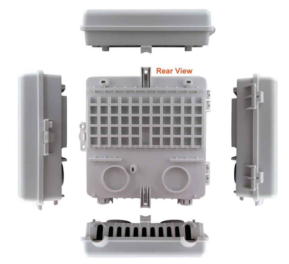
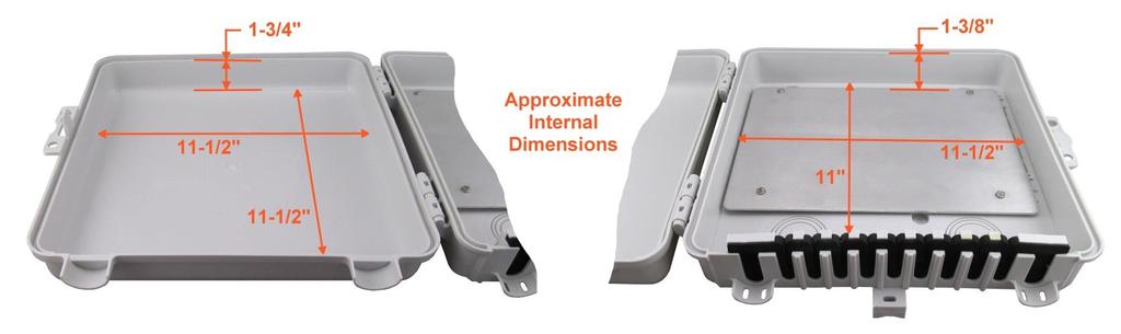
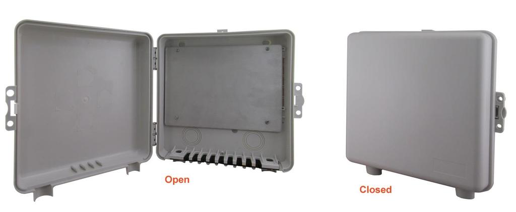
7 Additional Enclosure Views - 7 -
8 Technical Support If you have questions about this product, or if you experience difficulties during the installation, contact DX Engineering at (330) You can also us at: For best service, please take a few minutes to review this manual before you call. Warranty All products manufactured by DX Engineering are warranted to be free from defects in material and workmanship for a period of one (1) year from date of shipment. DX Engineering s sole obligation under these warranties shall be to issue credit, repair or replace any item or part thereof which is proved to be other than as warranted; no allowance shall be made for any labor charges of Buyer for replacement of parts, adjustment or repairs, or any other work, unless such charges are authorized in advance by DX Engineering. If DX Engineering s products are claimed to be defective in material or workmanship, DX Engineering shall, upon prompt notice thereof, issue shipping instructions for return to DX Engineering (transportation-charges prepaid by Buyer). Every such claim for breach of these warranties shall be deemed to be waived by Buyer unless made in writing. The above warranties shall not extend to any products or parts thereof which have been subjected to any misuse or neglect, damaged by accident, rendered defective by reason of improper installation, damaged from severe weather including floods, or abnormal environmental conditions such as prolonged exposure to corrosives or power surges, or by the performance of repairs or alterations outside of our plant, and shall not apply to any goods or parts thereof furnished by Buyer or acquired from others at Buyer s specifications. In addition, DX Engineering s warranties do not extend to other equipment and parts manufactured by others except to the extent of the original manufacturer s warranty to DX Engineering. The obligations under the foregoing warranties are limited to the precise terms thereof. These warranties provide exclusive remedies, expressly in lieu of all other remedies including claims for special or consequential damages. SELLER NEITHER MAKES NOR ASSUMES ANY OTHER WARRANTY WHATSOEVER, WHETHER EXPRESS, STATUTORY, OR IMPLIED, INCLUDING WARRANTIES OF MERCHANTABILITY AND FITNESS, AND NO PERSON IS AUTHORIZED TO ASSUME FOR DX ENGINEERING ANY OBLIGATION OR LIABILITY NOT STRICTLY IN ACCORDANCE WITH THE FOREGOING. DX Engineering 2017 DX Engineering, DXE, DX Engineering, Inc., Hot Rodz, Maxi-Core, DX Engineering THUNDERBOLT, DX Engineering Yagi Mechanical, EZ-BUILD, TELREX, Gorilla Grip Stainless Steel Boom Clamps, Butternut, SkyHawk, SkyLark, SecureMount, OMNI-TILT, RF-PRO-1B, AFHD-4 are trademarks of PDS Electronics, Inc. No license to use or reproduce any of these trademarks or other trademarks is given or implied. All other brands and product names are the trademarks of their respective owners. Specifications subject to change without notice
Grounding and Utility Enclosure
 Grounding and Utility Enclosure UE-1P UE-1P-INS Revision 1 DX Engineering 2006 P.O. Box 1491 Akron, OH 44309-1491 Phone: (800) 777-0703 Tech Support and International: (330) 572-3200 Fax: (330) 572-3279
60 Meter Mono-Band Conversion Kit for the DXE-MBVE-5A Multi-Band Vertical Antenna
 60 Meter Mono-Band Conversion Kit for the DXE-MBVE-5A Multi-Band Vertical Antenna DXE-MBVE-5A60MCK DXE-MBVE-5A60MCK-INS Revision 0a DX Engineering 2017 1200 Southeast Ave. - Tallmadge, OH 44278 USA Phone:
DXE-NCCFL Receive Filter Sets
 DXE-NCCFL Receive Filter Sets The advanced plug-in filter modules (DXE-NCCFL Series) offer frequency-specific receive system enhancements for the DXE- NCC-1 Receive Antenna Phasing Controller. All filter
BN-86 Upgrade Balun for Yagi Antennas
 BN-86 Upgrade Balun for Yagi Antennas DXE-BN86-UPG-15T, 15B, 20T and 20B DXE-BN86-UPG-INS Revision 0b DX Engineering 2017 1200 Southeast Ave. - Tallmadge, OH 44278 USA Phone: (800) 777-0703 Tech Support
RX Share Audio Switch
 RX Share Audio Switch DXE-RXSHARE DXE-RXSHARE-INS Revision 0 DX Engineering 2018 1200 Southeast Ave. - Tallmadge, OH 44278 USA Phone: (800) 777-0703 Tech Support and International: (330) 572-3200 Fax:
Balun Upgrade for the DXE-3X10 Skyhawk Antenna or DXE-2X7 Skylark Antenna
 Balun Upgrade for the DXE-3X10 Skyhawk Antenna or DXE-2X7 Skylark Antenna DXE-BAL-YAGI-UPG DXE-BAL-YAGI-UPG-INS Revision 0d DX Engineering 2017 1200 Southeast Ave. - Tallmadge, OH 44278 USA Phone: (800)
Two Element Phased Vertical Array System
 Two Element Phased Vertical Array System COM-PVS-160/80/40/30/20 COM-PVS-2-INS-Revision 7 COMTEK SYSTEMS 2011 P.O. Box 1491 - Akron, OH 44309-1491 USA Phone: (800) 777-0703 Technical Support and International:
40 Meter Vertical Antenna
 40 Meter Vertical Antenna COM-40VA COM-40VA-INS-Revision 1 COMTEK SYSTEMS 2016 1200 Southeast Ave. - Tallmadge, OH 44278 USA Phone: (800) 777-0703 Technical Support and International: (330) 572-3200 Fax:
Hot Rodz Adjustable Capacity Hat
 Hot Rodz Adjustable Capacity Hat DXE-HR-1P DXE-HR-1P-INS Revision 1b US Patent # 7,002,525 Shown installed on an optional Hustler resonator DX Engineering 2012 P.O. Box 1491 Akron, OH 44309-1491 USA Phone:
Vertical Antenna Matching Network
 Vertical Antenna Matching Network for the Hustler 5-BTV, 6-BTV and other Quarter Wave Monoband Vertical Antenna Systems DXE-VMN-1 DXE-VMN-1-INS Revision 1d DX Engineering 2017 1200 Southeast Ave. - Tallmadge,
RPA-2 HF Modular Receive Preamplifier
 RPA-2 HF Modular Receive Preamplifier DXE-RPA-2 DXE-RPA-2-INS Rev 0 U.S. Patent No. 7,319,435 DX Engineering 2017 1200 Southeast Ave. - Tallmadge, OH 44278 USA Phone: (800) 777-0703 Tech Support and International:
HMS Hairpin Matching Systems
 HMS Hairpin Matching Systems DXE-HMS-1P, DXE-HMS-2P, DXE-HMS-4P DXE-HMS-INS-Rev 1h For Use with 1-1/4 Inch through 3 Inch Booms Shown with optional Boom, Elements and Element Bracket with Gorilla Grip
RPA-2 HF Modular Receive Preamplifier
 RPA-2 HF Modular Receive Preamplifier DXE-RPA-2 DXE-RPA-2-INS Rev 1 U.S. Patent No. 7,319,435 DX Engineering 2018 1200 Southeast Ave. - Tallmadge, OH 44278 USA Phone: (800) 777-0703 Tech Support and International:
TW Antennas Mono and Multi-Band Vertical Dipole Antenna Systems
 TW Antennas Mono and Multi-Band Vertical Dipole Antenna Systems DXE-TW Series DXE-TW-SERIES-INS Revision 0c DX Engineering 2017 1200 Southeast Ave. - Tallmadge, OH 44278 USA Phone: (800) 777-0703 Tech
Radial Plate DXE-RADP-3. Installation Guide. DXE-RADP-3-INS-Rev 1a U.S. Patent Nos. 6,927,740 and D533,167
 Radial Plate DXE-RADP-3 Installation Guide DXE-RADP-3-INS-Rev 1a U.S. Patent Nos. 6,927,740 and D533,167 DX Engineering 2015 1200 Southeast Ave. - Tallmadge, OH 44278 USA Phone: (800) 777-0703 Tech Support
RPA-1 Preamplifier User Manual
 Page 12 RPA-1 Preamplifier User Manual DXE-RPA-1-INS-Revision 0 PATENT PENDING DX Engineering 2004 P.O. Box 1491 Akron, OH 44309-1491 Phone: (800) 777-0703 Tech Support and International: (330) 572-3200
Radial Plate DXE-RADP-3. Installation Guide. DXE-RADP-3-INS-Rev 0a Patented
 Radial Plate DXE-RADP-3 Installation Guide DXE-RADP-3-INS-Rev 0a Patented DX Engineering 2012 P.O. Box 1491 Akron, OH 44309-1491 USA Phone: (800) 777-0703 Tech Support and International: (330) 572-3200
Selecting and Installing Lightning Protection Devices
 Selecting and Installing Lightning Protection Devices A Whitepaper Revision 0 DXE-UE-1P Shown with Optional Equipment Mounted DX Engineering 2006 P.O. Box 1491 Akron, OH 44309-1491 Phone: (800) 777-0703
Near Vertical Incidence Skywave (NVIS) Antenna
 Antenna") Near Vertical Incidence Skywave (NVIS) Antenna DXE-NVIS-8040 DXE-NVIS-8040S DXE-NVIS-INS Revision 0 DX Engineering 2018 1200 Southeast Ave. - Tallmadge, OH 44278 USA Phone: (800) 777-0703 Tech Support
Near Vertical Incidence Skywave (NVIS) Antenna DXE-NVIS-8040 DXE-NVIS-8040S DXE-NVIS-INS Revision 0 DX Engineering 2018 1200 Southeast Ave. - Tallmadge, OH 44278 USA Phone: (800) 777-0703 Tech Support
RPA-1 Plus HF Preamplifier
 RPA-1 Plus HF Preamplifier DXE-RPA-1PLUS DXE-RPA-1PLUS-INS Rev 0a U.S. Patent No. 7,319,435 DX Engineering 2017 1200 Southeast Ave. - Tallmadge, OH 44278 USA Phone: (800) 777-0703 Tech Support and International:
00108/00110 INSTRUCTION MANUAL
 00108/00110 INSTRUCTION MANUAL Removable and Adjustable Mudflap System IMPORTANT! Please Read this Instruction Booklet prior to assembly of your Rock Tamer Kit. IMPORTANT! Exhaust Systems Note: Any modifications
One Shelf, Wall Mounted A/V Component Stand Installation Guide Model: EX101SS
 One Shelf, Wall Mounted A/V Component Stand Installation Guide Model: EX0SS For technical assistance or troubleshooting please call -855-994-3832. This product is intended for use only with Audio/Video
A Practical NVIS Antenna for Emergency or Temporary Communications
 A Practical NVIS Antenna for Emergency or Temporary Communications Rev. 0 Optimum for 40 and 80 Meters DX Engineering 2008 P.O. Box 1491 Akron, OH 44309-1491 Phone: (800) 777-0703 Tech Support and International:
Special Multi-Band Vertical Antenna UNUN UNUN, UNUN Bracket and UNUN Retrofit Information
 Special Multi-Band Vertical Antenna UNUN UNUN, UNUN Bracket and UNUN Retrofit Information DXE-UN-43 / DXE-UN-BRKT / DXE-UN-43-R (US Patent No. D597,086) DXE-UN-43-INS Revision 4b DX Engineering 2017 1200
Safety Awareness Barriers
 INSTALLATION INSTRUCTIONS FOR These safety awareness barriers are ideal for use in the manufacturing industry to provide a physical and visual means to warn people that hazards exist beyond the barrier.
Install Instructions. NewAge Steel Welded Tall Locker
 Kit Contains Full Width Adjustable Steel Shelves (4) Height-Adjustable Steel Leveling Legs (4) Aluminum Door Trim (2) 2.5 x ¼ Cabinet Mounting Lag Bolts (4) Large Zinc Plated Mounting Washers (4) 5/8 x
Single Arm Pole Mount. Installation Manual Edition v1.01. For models: UNI-SA/14 UNI-SA/21.5 UNI-SA/26 UNI-SA01-MAN
 Pole Mount Installation Manual 2016 Edition v1.01 For models: UNI-SA/14 UNI-SA/21.5 UNI-SA/26 UNI-SA01-MAN Table of Contents 1 1 2 3 4 5 5 Introduction Customer Support Project Essentials Assembly: Steps
Series 500. Owner s Manual. Analog Transmitters by Data Industrial. Data Industrial. Data Industrial 2/95 PN 72806
 Series 500 Analog Transmitters by Data Industrial Data Industrial Owner s Manual Data Industrial 2/95 PN 72806 Table of Contents Introduction... 1 4-20 ma Loop Supply Requirements... 2 Installation...
PATRIOT DOCKS ASSEMBLY INSTRUCTIONS
 6/1/2008 PATRIOT DOCKS ASSEMBLY INSTRUCTIONS Congratulations on your new Patriot Dock purchase. This manual contains instructions to assemble basic dock configurations for use at typical shoreline application.
Tilting, Swiveling & Rotating Flat Panel Wall Mount
 Tilting, Swiveling & Rotating Flat Panel Wall Mount Model: VXA980TC +5 to -5 +5 to -5 Supports most 0-80 Flat Panel TVs Maximum Weight Capacity: 32 lbs. Supports VESA Sizes up to 600x500 For technical
Tilting & Swiveling Flat Panel Wall Mount Installation Guide Model: AXS2040
 Tilting & Swiveling Flat Panel Wall Mount Installation Guide Model: AXS2040 20-40 66 lbs. Supports VESA sizes up to: 200x200 For technical assistance or troubleshooting please call 1-855-994-2825 or visit
Installation and Assembly: Recessed Cable Management and Power Storage Accessory Box
 Installation and Assembly: Recessed Cable Management and Power Storage Accessory Box Models: IBA2AC, IBA2AC-W 2300 White Oak Circle Aurora, Il 60502 (800) 865-2112 Fax: (800) 359-6500 www.peerlessmounts.com
LJ element beam for 10 or 12 meters INSTRUCTION MANUAL. CAUTION: Read All Instructions Before Operating Equipment
 LJ-113 3 element beam for 10 or 1 meters INSTRUCTION MANUAL CAUTION: Read All Instructions Before Operating Equipment 308 Industrial Park Road Starkville, MS 39759 USA Tel: 66-33-9538 Fax: 66-33-6551 VERSION
Page 1 of 18. SunRail System Installation Instructions
 Page 1 of 18 SunRail System Installation Instructions Page 2 of 18 SunRail Stainless Steel Railing Installation Guide Table of Contents Before You Begin 3 Installing Surface Mount Bases for a Two Rail
Beverage Feedpoint Matching System
 Beverage Feedpoint Matching System DXE-BFS-1 Patent Pending DXE-BFS-1-INS Revision 3c DX Engineering 2017 1200 Southeast Ave. - Tallmadge, OH 44278 USA Phone: (800) 777-0703 Tech Support and International:
INSTALLATION INSTRUCTIONS
 INSTALLATION INSTRUCTIONS Polaris Universal Projector Mount Model: NORTH AMERICA 1321 S. State College Blvd. Fullerton, CA 92831 USA USA and Canada Phone: 1.800.368.9700 Fax: 1.800.832.4888 Other Locations
One Revolution Tube Cutter
 One Revolution Tube Cutter Series 9060 Tube & Pipe Cleaners Tube Testers Tube Plugs Tube Removal Tube Installation Operating and Maintenance Instructions www.elliott-tool.com Table Of Contents Introduction...
INSTALLATION INSTRUCTIONS
 CREATING POSITIVE CUSTOMER EXPERIENCES INSTALLATION INSTRUCTIONS Universal Low Profile Tilt Mount for 42 to 63 Flat Panels NORTH AMERICA 3130 East Miraloma Avenue Anaheim, CA 92806 USA USA and Canada Phone:
Tilting Flat Panel Wall Mount Installation Guide
 Tilting Flat Panel Wall Mount Installation Guide Model: A580TM Easy installation Built-in level for easy positioning Safety bolts lock the TV on the mount Easy to adjust tilt angles: +5 to -15 degrees
Single-Sliding Header Mount INSTALLATION INSTRUCTIONS
 1-800-701-4782 Single-Sliding Header Mount INSTALLATION INSTRUCTIONS GATEWAY SO# OPENING SIZE: W x H PULLEY SYSTEM: YES / NO Upon receiving your Gateway Door, inspect packaging and contents for freight
GB-AVSTOR5 Ceiling Equipment Storage Box with Pipe Coupler
 Ceiling Equipment Storage Box with Pipe Coupler INSTALLATION INSTRUCTIONS CREATING POSITIVE CUSTOMER EXPERIENCES 9534-500-021-00 Contents Weight Limit... 2 Warning Statements... 2 Installation Tools...
QuadroMAX. Installation Manual. QM Series. LED Outdoor Lighting Fixtures REV: 3/22/16
 QuadroMAX LED Outdoor Lighting Fixtures Installation Manual QM Series REV: 3/22/16 BEFORE YOU BEGIN Read these instructions completely and carefully. WARNING Risk of fire or electric shock. Luminaire wiring
AM95 Installation Guide
 1321 S. State College Blvd., Fullerton, CA 92831 USA Included Components: Maximum Flat Panel Weight: 95 lb. / 43.1 kg. M4 X 25mm M5 X 25mm M6 X 12mm (Qty 2) M6 X 25mm M8 X 25mm Allen Key Plastic Cover
The Heritage Pergola
 Eye Level Corporation One Trefoil Drive Trumbull, CT 06611 USA Phone: 888.782.1760 Fax: 888.782.1761 www.@eyelevelliving.com The Heritage Pergola Installation Instructions ARBORS COLUMNS HOSE REELS MAILBOX
HDRo Owner s Manual. 12 Month Limited Warranty. Indoor/Outdoor Amplified HD Radio Antenna
 12 Month Limited Warranty Owner s Manual Audiovox Electronics Corporation (the company) warrants to the original purchaser of this product that should this product or any part thereof, under normal use
Installation Instructions PP-FCMA
 Installation Instructions PP-FCMA Step 1 Carefully remove a 24 (610mm)x48 (1120mm) or two 24 (610mm)x24 (610mm) suspended ceiling tiles. Step 2 Install the four (4) each ¼ x3 eye bolts securely into the
ANTENNA SYSTEMS. PTX Offset Antenna.60/.76/.90./1.1m INSTALLATION & ASSEMBLY INSTRUCTIONS
 ANTENNA SYSTEMS PTX Offset Antenna.60/.76/.90./1.1m INSTALLATION & ASSEMBLY INSTRUCTIONS LIMITED TWELVE (12) MONTH WARRANTY This PATRIOT ANTENNA equipment is warranted to be free from defects in material
Assembly & Installation Instructions
 Wall Mount Garden Hose Reel Model 1041 Assembly & Installation Instructions 1 2 3 4 5 6 8 9 10 12 15 7 11 10 16 17 13 14 CONTENTS QUESTIONS? PROBLEMS? Please DO NOT contact or return this item to the retailer.
INSTALL INSTRUCTIONS WELCOME TO THE NEWAGE PERFORMANCE CABINETRY SERIES NEWAGE STEEL WELDED CABINETRY
 NEWAGE STEEL WELDED CABINETRY WELCOME TO THE NEWAGE PERFORMANCE CABINETRY SERIES ALL CABINETS MUST BE MOUNTED TO STUDS ON A SECURE WALL, AS PER THESE INSTRUCTIONS. FAILURE TO DO SO MAY RESULT IN SERIOUS
K1FO 12 ELEMENT 144/147 MHz YAGI
 K1FO 12 ELEMENT 144/147 MHz YAGI WARNING: INSTALLATION OF THIS PRODUCT NEAR POWER LINES IS DANGEROUS. FOR YOUR SAFETY FOLLOW THE INSTALLATION DIRECTIONS. Ariane Arrays, Inc. Copyright 2006 201 Hopedale
Receiver Guard 5000HD and 5000 Receiver Front-End Protectors
 Receiver Guard 5000HD and 5000 Receiver Front-End Protectors DXE-RG-5000HD and DXE-RG-5000 DXE-RG-5000-INS Rev 1a DX Engineering 2017 DX Engineering - 1200 Southeast Ave. - Tallmadge, OH 44278 USA Phone:
OMEGA. Communications Interface Cabinet. Antenna Installation Manual
 Ω OMEGA Communications Interface Cabinet Antenna Installation Manual 0049-0706-004 The products and programs described in this User s Guide are licensed products of Telenetics Corporation. This User s
ASSEMBLY AND INSTALLATION INSTRUCTIONS R , 12, 15, 17, 20, 30, 40 Meters (5/99) COMMUNICATIONS ANTENNAS
 COMMUNICATIONS ANTENNAS") ASSEMBLY AND INSTALLATION INSTRUCTIONS R7000 10, 12, 15, 17, 20, 30, 40 Meters COMMUNICATIONS ANTENNAS 951465 (5/99) WARNING THIS ANTENNA IS AN ELECTRICAL CONDUCTOR. CONTACT WITH POWER LINES CAN RESULT
ASSEMBLY AND INSTALLATION INSTRUCTIONS R7000 10, 12, 15, 17, 20, 30, 40 Meters COMMUNICATIONS ANTENNAS 951465 (5/99) WARNING THIS ANTENNA IS AN ELECTRICAL CONDUCTOR. CONTACT WITH POWER LINES CAN RESULT
INSTALLATION INSTRUCTIONS
 INSTALLATION INSTRUCTIONS SELF LEVELING RADAR ANTENNA MOUNT MODEL 400G QUESTUS MARINE, INC. PO BOX 9 MARBLEHEAD, MA 01945 1-800-RADAR66 TEL 781.639.1900 FAX 781.639.1905 www.questusmarine.com INSTALLATION
Balun Mounting Bracket for COMTEK Baluns and Wire Antennas
 Balun Mounting Bracket for COMTEK Baluns and Wire Antennas Patent Pending DXE-WA-BMB DXE-WA-BMB-INS Rev 0b Shown with optional parts DX Engineering 2017 DX Engineering - 1200 Southeast Ave. - Tallmadge,
INSTRUCTION MANUAL. Specifications Electrical. Front-To-Back Ratio VSWR at Resonance Less than 1.5:1 Nominal Impedance. Mechanical
 300 Industrial Park Road, Starkville, MS 39759 Ph: (662) 323-8538 FAX: (662) 323-6551 TH-3JRS Tri-band HF 3 Elements Beam Covers 10, 15 and 20 Meters INSTRUCTION MANUAL WARNING Installation of this product
Owner s Manual. Tilt Wall Mount for Flat and Curved Screens Security Version
 Owner s Manual Tilt Wall Mount for Flat and Curved Screens Security Version Model: DWTSC3255MUL 200x200 / 300x300 / 400x200 / 400x400 55 MAX 99 lb. (45 kg) MAX Este manual esta disponible en español en
Directed Energy, Inc Oakridge Dr., Suite 100, Fort Collins, CO
 PCO-7121 Laser Diode Driver Module Operation Manual Directed Energy, Inc. 1609 Oakridge Dr., Suite 100, Fort Collins, CO 80525 sales@ixyscolorado.com www.ixyscolorado.com Contents Contents... 3 Safety...
Owner s Manual GS2010 Garden Seeder/Fertilizer. Caution: Carefully read all Rules and Instructions for Safe Operation.
 Manufacture s Limited Warranty for The limited warranty set forth below is given by Precision Products, Incorporated with respect to new merchandise purchased and used in the United States, its possessions
INSTALLATION MANUAL SONANCE SOUNDBARS SB46 M AND SB46 L. Introduction. Box Contents. Wall Mount Installations
 INSTALLATION MANUAL SONANCE SOUNDBARS SB46 M AND SB46 L Introduction Thank you for purchasing the Sonance Soundbar SB46 M or SB46 L. When properly installed your new Soundbar will give you years of entertainment
INSTALLATION INSTRUCTIONS
 INSTALLATION INSTRUCTIONS P4263F Universal Low Profi le Flat Mount for 42 to 63 Flat Panels NORTH AMERICA 3130 East Miraloma Avenue Anaheim, CA 92806 USA USA and Canada Phone: 1.800.368.9700 Fax: 1.800.832.4888
Installation Manual XRL Solar Rail System
 Installation Manual XRL Solar Rail System Solar Mounting Solutions June 2009 www.ironridge.com 2009 IronRidge, Inc. All Rights Reserved Version 1.0 2 XRL Solar Rail System Installation Guide Introduction
CUTTING THE PIPE: BLUE DUCT Pipe can be easily cut using a Circular Saw or Reciprocal Saw. Trim all edges as necessary.
 Installation Instructions In the past it has been IMPOSSIBLE to install an air and water tight underground system. BLUE DUCT (AKDUCT ) has produced a user friendly system that will reduce the amount of
INSTRUCTION MANUAL VB-66DX. 6-Meter 6-Element Beam. Preparation For Assembly. General Description
 VB-66DX 308 Industrial Park Road Starkville, MS 39759 USA Ph: (662) 323-9538 FAX: (662) 323-6551 6-Meter 6-Element Beam INSTRUCTION MANUAL General Description The Hy-Gain Model 66DX is a full sized 6-
( ) CanPRO. Recommended Handle Turns: Can Size Diameter Handle Turns #2 3" 3 Revolutions #5 5" 5 Revolutions #10 6" 6 Revolutions.
 CanPRO. Recommended Handle Turns: Can Size Diameter Handle Turns #2 3 3 Revolutions #5 5 5 Revolutions #10 6 6 Revolutions.") 56050 - ( ) CanPRO OPERATING INSTRUCTIONS Important 1. To get the best operation and life from your machine, please read and comply with these instructions. 2. Clean machine thoroughly before and after
56050 - ( ) CanPRO OPERATING INSTRUCTIONS Important 1. To get the best operation and life from your machine, please read and comply with these instructions. 2. Clean machine thoroughly before and after
SERIES M MIXER MASTS
 SERIES M MIXER MASTS T AB L E O F C O N T E N T S V e n d o r D a t a Material Data Sheet 4-in. Mixer Mast Specification 3-in. Mixer Mast Specification 2 - in. M i x e r M a s t S p e c i f i c a t i o
Series 1600 WeatherGuard Dock Enclosure
 Fairborn USA Inc. 205 Broadview Street Upper Sandusky, OH 43351 1-800-262-1188 Fax 1-419-294-4980 Series 1600 WeatherGuard Dock Enclosure All Models! WARNING Do not install this product unless you read
TENNADYNE. Aluminum with a PhD. Tennadyne ASSEMBLY INSTRUCTIONS MODEL: T Log Periodic Antennas SPECIFICATIONS:
 TENNADYNE Aluminum with a PhD ASSEMBLY INSTRUCTIONS MODEL: T10-100224 SPECIFICATIONS: FREQUENCY COVERAGE 13-33 MHz FORWARD GAIN 6.1 dbd ½ POWER BEAMWIDTH 52 DEGREES F:B RATIO To 25 Db (Rises with frequency)
WARRANTY REGISTRATION AND POLICY
 WARRANTY REGISTRATION AND POLICY Buhler Manufacturing products are warranted for a period of twelve (12) months from original date of purchase, by original purchaser, to be free from defects in material
Installation Manual Tilt Leg
 Installation Manual Tilt Leg Solar Mounting Solutions March www.ironridge.com 2010 IronRidge, Inc. All Rights Reserved Version 2.0 2 Tilt Leg Installation Guide Introduction The Tilt Leg is a flexible
Installation and Assembly: Articulating Swivel Arm for 37" - 60" Flat Panel Displays
 Installation and Assembly: Articulating Swivel Arm for 37" - 60" Flat Panel Displays Models: PLA60, PLA60-S, PLAV60, PLAV60-S Max UL Load Capacity: 175 lb (79 kg) 2300 White Oak Circle Aurora, Il 60502
Owner s Manual & Safety Instructions
 Owner s Manual & Safety Instructions Save This Manual Keep this manual for the safety warnings and precautions, assembly, operating, inspection, maintenance and cleaning procedures. Write the product s
INSTALLATION INSTRUCTIONS
 CREATING POSITIVE CUSTOMER EXPERIENCES INSTALLATION INSTRUCTIONS PDS-PLUS Universal Projector Mount Model: NORTH AMERICA 3130 East Miraloma Avenue Anaheim, CA 92806 USA USA and Canada Phone: 1.800.368.9700
INSTRUCTION MANUAL. Specifications Mechanical. 1 5/8 to 2 1/16 O.D. (41mm to 52mm)
") 308 Industrial Park Road Starkville, MS 39759 USA Ph: (662) 323-9538 FAX: (662) 323- General Description Model VB-25FM 2-Meter 5 Elements Beam INSTRUCTION MANUAL This antenna is a 5-element, 2-meter beam
308 Industrial Park Road Starkville, MS 39759 USA Ph: (662) 323-9538 FAX: (662) 323- General Description Model VB-25FM 2-Meter 5 Elements Beam INSTRUCTION MANUAL This antenna is a 5-element, 2-meter beam
Installation and Assembly: Recessed Cable Management and Power Storage Accessory Box
 Installation and Assembly: Recessed Cable Management and Power Storage Accessory Box Models: IBA3, IBA3-W 2300 White Oak Circle Aurora, Il 60502 (800) 865-2112 Fax: (800) 359-6500 www.peerlessmounts.com
The MFJ-1754 can be mounted on any 1" to 1 1/2" mast (conductive or non conductive.)
") INTRODUCTION: The MFJ-1754 is designed for use on the 2 meter and the 70 centimeter bands. On the 2 meter band the MFJ-1754 behaves as a vertical 1/4 wave antenna, however on 70 centimeter band the MFJ-1754
INTRODUCTION: The MFJ-1754 is designed for use on the 2 meter and the 70 centimeter bands. On the 2 meter band the MFJ-1754 behaves as a vertical 1/4 wave antenna, however on 70 centimeter band the MFJ-1754
JK-65 Five Element 6M Yagi
 JK-65 Five Element 6M Yagi PO Box 266, Croton Falls, NY 10519-0266 845.228.8700 (TEL) 845.279.5526 (FAX) info@jkantennas.com Page 1 of 8 JK Antennas Limited Warranty and Liability JK Antennas ( Manufacturer
Feedline Voltage Coupler
 Feedline Voltage Coupler DXE-FVC-1 DXE-FVC-1-INS Rev. 5b DX Engineering 2017 1200 Southeast Ave. - Tallmadge, OH USA Phone: (800) 777-0703 Tech Support and International: (330) 572-3200 Fax: (330) 572-3279
INSTALLATION INSTRUCTIONS FOR BALCO, INC. NBR SERIES EXPANSION JOINT COVER SYSTEMS
 2626 South Sheridan PO Box 17249 Wichita, Kansas 67217 Phone: (316) 945-9328 Fax: (316) 945-0789 INSTALLATION INSTRUCTIONS FOR BALCO, INC. NBR SERIES EXPANSION JOINT COVER SYSTEMS 2010, Balco, Inc. 09/14/10
GENERAL INSTALLATION GUIDE: WARRANTY: PRODUCT INFORMATION T F
 GENERAL INSTALLATION GUIDE: Unless otherwise indicated, all Seven Oaks M.U. Architectural Products materials are to be used for decorative purposes only. All products must be installed using ample amount
Ambient Weather EZ Weather Station Tripod and Mast Assembly for AcuRite Weather Stations User Manual
 Ambient Weather EZ-48-100 Weather Station Tripod and Mast Assembly for AcuRite Weather Stations User Manual Table of Contents 1. Introduction... 1 2. Accessories... 1 3. Parts... 2 4. Warnings... 2 5.
HEXXAGONAL BEAM Mark 2
 HEXXAGONAL BEAM Mark 2 DXE-HEXX-5TAP-2, DXE-HEXX-1TAP-2 DXE-HEXX-BEAM-MARK2-INS Rev. 6b DX Engineering 2018 1200 Southeast Ave. - Tallmadge, OH 44278 USA Phone: (800) 777-0703 Tech Support and International:
Worktop. Weight Capacity. 100 lbs. 21 Corner Worktop. 48 Worktop. Fits over 2 Cabinets. 72 Worktop. Fits over 3 Cabinets. 200 lbs. 150 lbs.
 Bold.0 Warning: Excessive weight hazard! Use two or more people to move, assemble or install cabinets and locker to avoid back injury. Do not leave children unattended near cabinets. High risk of tipping
Models 2030 and 2040
 Models 2030 and 2040 Overview... 2 Tools Needed... 2 Hardware... 2 Assembly... 3-8 Installation... 9 Operation... 9 Maintenance... 10 Accessories... 10 Limited Warranty... 10 Document # 101290 0607 Printed
Installation Instructions Hustler Collinear Two Meter Fixed Station Antenna Master Gainer Model G6-144B
 Installation Instructions Hustler Collinear Two Meter Fixed Station Antenna Master Gainer Model Warning INSTALLATION OF THIS PRODUCT NEAR POWER LINES IS DANGEROUS. FOR YOUR SAFETY, FOLLOW THE INSTALLATION
Models 2130 and 2140
 Models 2130 and 2140 Overview... 2 Tools Needed... 2 Hardware... 2 Assembly... 3-10 Installation...11 Operation... 11 Maintenance... 12 Accessories...12 Limited Warranty... 12 Printed in USA 2007 Perform
Models 2130 and 2140
 Models 2130 and 2140 Overview... 2 Tools Needed... 2 Hardware... 2 Assembly... 3-10 Installation...11 Operation... 11 Maintenance... 12 Accessories...12 Limited Warranty... 12 Perform the following sequence
Installation and Operation Manual MSI. Multi-Sensor Interface Hub. Interface Module for all Sensors Network and Wireless CAUTION
 Installation and Operation Manual MSI Multi-Sensor Interface Hub Interface Module for all Sensors Network and Wireless CAUTION This equipment complies with the limits for a Class B digital device, pursuant
INSTRUCTION MANUAL. Model 18AVQII Five Band Vertical Antenna 10, 15, 20, 40, 80 Meter. General Description. Theory of Operation
 Model 18AVQII Five Band Vertical Antenna 10, 15, 20, 40, 80 Meter 308 Industrial Park Road Starkville, MS 39759 (662) 323-9538 Fax: (662) 323-5803 INSTRUCTION MANUAL General Description The Hy-Gain 18AVQII
2.0. Select Rail & Stair Kit Assembly and Installation Instructions BOM V2 5/13. Owner's Manual. Version
 Select Rail & Stair Kit Assembly and Installation Instructions PLEASE READ OWNER'S MANUAL COMPLETELY BEFORE ASSEMBLING YOUR RAIL OR STAIR KIT. 34106886BOM V2 5/13 Models 73012418 / 73012436 / 73012424
INSTALLATION INSTRUCTIONS
 INSTALLATION INSTRUCTIONS Premier Mounts Tilting Wall Mount Model: TWM-085 For use with Panasonic 85 Flat Panel NORTH AMERICA 3130 East Miraloma Avenue Anaheim, CA 92806 USA USA and Canada Phone: 1.800.368.9700
Owner s Manual ODYSSEY BENCH MODEL. O4100B shown REV E. Southern Avenue, Phoenix, AZ USA Workhorseproducts.
 Owner s Manual ODYSSEY BENCH MODEL O4100B shown 67-1375 REV 218 3730 E. Southern Avenue, Phoenix, AZ 85040 USA 800-778-8779 Workhorseproducts.com 1 Table of Contents I. Introduction & Safety Information.
Installation Instructions Kit, Base Rail Bracket Part # 31413
 Installation Instructions Kit, Base Rail Bracket Part # 31413 Dealer / Installer: End User: Provide a copy of these Instructions to the end user of this product. These Instructions provide important operating
Assembly & Installation Instructions
 Wall Mount Hose Reel Model 04-GH Configuration Pulls the hose out straight away from the wall. Configuration Pulls the hose out along side the wall. Assembly & Installation Instructions Version 0409 A
Read this user s manual before use to ensure proper operation. Keep the manual on hand for reference in case there is a problem.
 LD3500 Series CONTENTS Read this user s manual before use to ensure proper operation. Keep the manual on hand for reference in case there is a problem. Warranty lnformation Maintenance Exploded View Features
Owner s Manual LSP38 38 Lawn Sweeper
 Owner s Manual LSP38 38 Lawn Sweeper Manual Contents Safety Instructions Assembly Operation Maintenance Parts Warranty 2 4-13 2 11 14-15 16 Your Lawn Sweeper Congratulations on your purchase of a new Precision
Ambient Weather EZ Stable Mounting Kit with Mast for AcuRite Weather Stations User Manual
 Ambient Weather EZ-30-12-100 Stable Mounting Kit with Mast for AcuRite Weather Stations User Manual Table of Contents 1. Introduction... 1 2. Accessories... 1 3. Parts... 2 4. Warnings... 2 5. Recommended
Performance 2.0 Series
 Performance. Series Warning: Excessive weight hazard! Warning: Excessive weight hazard! Use two or more people to move, assemble, or install cabinets and locker to avoid back injury. Do not leave children
ASSEMBLY INSTRUCTIONS
 AVSC-2123 Audio Video System ASSEMBLY INSTRUCTIONS PATENT PENDING FOR YOUR SAFETY, PLEASE FOLLOW THESE PRECAUTIONS:! ALWAYS REMOVE THE TV AND OTHER EQUIPMENT FROM THE FURNITURE PRIOR TO MOVING THE ASSEMBLED
Sonoma Outdoor Kitchen Pergola. Assembly Instructions
 Sonoma Outdoor Kitchen Pergola Assembly Instructions Introduction Thank you for your purchase from The Outdoor GreatRoom Company. This pergola has been engineered and manufactured in the USA. This user