CHECK OUT OUR WEBSITE SOME TIME FOR PLENTY OF ARTICES ABOUT SELF DEFENSE, SURVIVAL, FIREARMS AND MILITARY MANUALS.
|
|
|
- Sylvia Garrett
- 6 years ago
- Views:
Transcription

1 CHECK OUT OUR WEBSITE SOME TIME FOR PLENTY OF ARTICES ABOUT SELF DEFENSE, SURVIVAL, FIREARMS AND MILITARY MANUALS. Thank you for purchasing our ebook package.
2 *FM i
3 ii
4 Preface This manual explains how to employ the effective jamming techniques referenced in FM Instructions are presented to the mission planner for calculating the minimum jammer power output requirements and the maximum distance a jammer can be placed from a target receiver based upon the jammer s power output. This information can be found by using the electronic warfare jamming calculator (appendix). Doctrine, tactics, techniques, and procedures in this field manual are intended for commanders and their staffs, division tactical operation centers, technical control and analysis elements (TCAEs), mission management personnel, and other personnel who plan or conduct jamming operations. This publication applies equally to active Army and Reserve Components. The proponent of this publication is Headquarters, United States Army Training and Doctrine Command. Send comments and recommendations on DA Form 2028 directly to the Commander, United States Army Intelligence School, Fort Devens (USAISD), ATTN: ATSI-ETD-PD, Fort Devens, MA Unless this publication states otherwise, masculine nouns and pronouns do not refer exclusively to men. iii
5 CHAPTER 1 Introduction Regardless of the terminology, most scholars would agree that communications involve at least four basic elements: transmitter, message, medium, and receiver. Communications occur when the receiver understands the idea sent by the transmitter well enough to provide some form of feedback. This publication approaches those communications that must rely on the electromagnetic spectrum as a medium to convey messages. It focuses on the disruption of the listener s ability to receive. IMPORTANCE OF COMMUNICATIONS The execution of the AirLand Battle Doctrine requires the skillful use of resources, target acquisition, and strike capability. To do this, a timely and responsive working relationship must exist between the respective combat forces. Reliable communications are needed to achieve this goal. The lack of communications can affect the outcome of any battle. IMPACT OF JAMMING ON COMMUNICATIONS Jamming is an electronic countermeasures (ECM) technique which supports intelligence and electronic warfare (IEW) doctrine. IEW doctrine directs that jamming be integrated into various phases of combat operations. Jamming degrades communications by reducing or denying the enemy's ability to pass key information at critical times and can cause enemy operators to become irritated, confused, or misled during offensive, defensive, or retrograde operations. When applied successfully, jamming can contribute to the failure of those actions which depend on communications using the electromagnetic spectrum. For example, an enemy fire direction 1-1
6 net must communicate in order to function. Proper jamming can force the net to change frequencies, reestablish communications, increase power output, or switch to a less reliable means of communications. ELECTRONIC WARFARE SUPPORT MEASURES SUPPORT Electronic warfare support measures are the primary source of information used to identify and develop jamming targets. The primary function of electronic warfare support measures is to gather information on the enemy s electronic systems. Electronic warfare support measures information can be passed directly to our analytical systems where it is correlated with data collected from multiple sources and used to determine the enemy's locations and intentions. From listening to the enemy s transmissions, we gain significant information about his electronic systems. Some of this information is used to direct our actions to reduce his combat effectiveness by interfering with his electronic systems. Further, it assists us to identify enemy targets and position our equipment to best disrupt or deny the enemy s use of his systems. The techniques employed to deny the enemy s use of his electronic systems area part of ECM called TO JAMMING jamming. Jamming is the action taken to reduce or deny the enemy s effective use of his electronic systems. Indiscriminate jamming wastes resources, could impede friendly communications, or could attract artillery fire. Consequently, jamming operators need to know exactly who, what frequency, and when to jam. To obtain this information, mission planners require data supplied through electronic warfare support measures. We listen to and locate enemy emitters to gain this information; not only to correlate it with other data for intelligence production, but to identify data needed to deny the enemy the use of his electronic systems. Electronic warfare support measures also provide technical data on the enemy's ability to jam friendly electronic systems. This information enables us to conduct protective measures to ensure our continued use of friendly electronic systems. The commander s decision to use jamming is influenced by several factors. The key factor is timing. Intercepting, direction finding (DF), and jamming cannot be conducted simultaneously against the same targeted communications link. The identifiable electronic signature created by jamming signals readily exposes friendly jammer locations. The tactical commander should treat ECM assets the same as artillery assets, because ECM mission results on communications can be as devastating as artillery on personnel and equipment. ECM assets are deployed to support committed units based on their mission priority, DECISION TO JAM the capabilities of available systems, and potential enemy actions. In the planning phase, thoughts should reflect the relative scarcity of ECM assets, their limitations, and their transient effects. The commander must balance the negative aspects of jamming operations against the positive tactical advantages of disrupting enemy communications. Jamming, when integrated into combat operations, must support the commander s battle plan. IEW doctrine dictates that commanders will integrate jamming with fire support and 1-2
7 maneuver forces to disrupt and confuse enemy forces during offensive, defensive, or retrograde operations. The commander s decision to employ jamming is carried out by military intelligence (MI) units and should be coordinated with the fire support element and integrated into the commander s fire support plan. These MI units detect, identify, and locate enemy communications nets and intercept their traffic to provide the commander with intelligence. The commander uses this intelligence to decide when and where to employ jamming in his concept of the operation. The MI units also direct ECM against enemy communications, jamming those based on the commander s decision. This capability to locate the enemy, to intercept the enemy s messages, and to hamper the enemy s operations at critical periods contributes directly and indirectly to the effectiveness of the friendly commander s concept of the operation. Enemy nets, which routinely pass information of intelligence value, should be identified and monitored. Other nets, such as those having a high tactical value to the enemy but little or no intelligence value to friendly forces, could be attacked with jammers or fire support depending on the tactical situation. Enemy secure communications may also be jammed with the intention of drawing the enemy into clear voice communications, thus allowing interception and further identification. Enemy jammers should be located, reported, and destroyed based on the demands of the tactical operation. Guidance for jamming, destroying, or exploiting enemy electronic emitters should be reviewed before each tactical operation. Additionally the TABOO, RESTRICTED, and GUARDED frequency lists must be reviewed prior to the execution of all jamming missions (see FM 34-40). Jamming should interrupt or disrupt the enemy s communication at decisive moments in the battle, for example, when key information needs to be passed or new instructions are required. Jamming may be effective for only the short periods that the enemy needs to take evasive action or to execute countermeasures. Jammers need to be used judiciously and moved often to avoid their destruction. Jammers support other combat actions by Disrupting key command and control nets, thus slowing or disorganizing the enemy in critical situations. Denying the enemy the ability to react to changes on the battlefield. Reducing the effectiveness of enemy fire support and air control nets. EMPLOYMENT OF JAMMING There are three steps in employing jamming. The first step concerns information collection and target acquisition. The second step involves planning the jamming mission. The third step is the execution of the jamming mission. This sequence is also called the decide, detect, and deliver method. The field commander is confronted with an enemy electronic array that comprises thousands of emitters and hundreds of communication nets. Collectively this emitter density is meaningless unless the emitters are sorted by Function. Position in a net. Position on the battlefield. Ability to affect the combat plan. Once the enemy emitter has been identified and located, this information flows to a coordination center where an interface occurs between 1-3
8 intelligence and operations. Based on this information the commander provides the guidance on whether to jam, destroy, deceive, or intercept for intelligence. As often as possible, this decision must be a part of the initial planning and coordination. When the decision is to intercept for intelligence purposes, it must be continually reevaluated to determine whether to continue collecting, to initiate jamming, or to destroy. The commander provides the guidance to the TCAE or the staff to identify certain nets that have a high tactical value to the enemy, but minimal or no intelligence value to friendly forces. Enemy command nets of units in contact, fire direction nets, and enemy target acquisition systems usually meet this criterion. As these nets are identified and located, they are jammed or destroyed in accordance with the commander s attack guidance. Jamming must complement the concept of operation. Jamming provides the commander with time to reactor time to change his estimate to gain the tactical advantage. To maintain this tactical advantage, jamming would best be used against priority targets and with careful timing to achieve the desired tactical results. 1-4
9 CHAPTER 2 Integrating Jamming Into Combat Operations The objective of jamming is to disrupt the enemy s effective use of his combat forces by reducing the effectiveness of his communications. The function of jamming is to disrupt or deny the enemy the reception of his electromagnetic signals radiating from his radio transmitters. Jamming can be subtle and difficult to detect, or it can be overt and obvious when mission requirements arise which override survivability. Jamming integration is explained in a step-bystep process (Table 2-1), which is based on the following war-game scenario: The mechanized division s commander directs the G3 to plan an operation to seize Hill 322. Intelligence reports indicate elements of the enemy's 231st Motorized Rifle Regimsnt are active in this area. The G3, in coordination with the G2, tasks the collection management and dissemination section to determine the enemy unit's location. The operation plan requires the division to attack through the regimental area. The 2d Brigade will lead the main attack and the 1st Brigade will conduct a supporting attack. 2-1
10 The first three steps are always accomplished by close coordination between the G2 and G3. These actions are never formally labeled, except as a part of a mental war-gaming of a sequence of actions and counteractions. These three steps are a form of tactical threat analysis, which identifies potential threats posed by enemy maneuver or weapon systems. Identified potential threats are then placed in priority order for jamming. The second three steps involve the technical considerations for jamming. FOCUS ON THE TACTICAL OBJECTIVE In step 1 (Figure 2-1), the G3 is acting for the Until this is done, jamming support cannot be commander. The G3 provides the same focus for integrated into the combat operation. integrating jamming as he would for integrating The initial guidance provided by the G3 makes any other division weapon system. In the planning and coordinating easier for the mission electronic warfare annex of the operation order, managers. An artillery unit cannot furnish the G3 directs that priority jamming support be integrated support until it receives the necessary provided to the 2d Brigade. This, in effect, data on where and when to fire. Likewise, focuses the jamming support on a specific unit or jamming cannot support combat operations operation and establishes the guidelines for effectively until it is focused on the threat integrating jamming into the combat operation. confronting our forces. 2-2
11 This initial focusing step narrows the area of concentration. It also identifies any conflicts among jamming, intelligence collection, and friendly use of the electromagnetic spectrum. This conflict resolution involves the G2, G3, signal officer, and MI assets to perform the overall assessment of the target and friendly force s use of the electromagnetic spectum. If jamming is integrated into the operation, the signal officer may have to realign the signal operation instructions. PLACE ENEMY UNITS IN PRIORITY ORDER In step 2 (Figure 2-2), the G2 and G3 consider based on their potential threat to the mission. the enemy units that could prevent the (In combat, priorities are normally situation accomplishment of the division s mission. These dependent.) units are placed in a priority order for jamming, 2-3

12 PLACE IDENTIFIED SYSTEMS AND FUNCTIONS IN PRIORITY ORDER In step 3 (Figure 2-3), the G2 and G3 identify the various weapons systems and threat functions available to the units listed in step 2. These weapons systems and threat functions are then placed in priority order on the basis of the greatest danger to the attacking friendly force. The second and third steps are constrained to fit into the specific guidelines as directed by the G3 (in step 1). The further the mission progresses on the battlefield, the more specific the direction becomes. Enemy Reconnaissance In step 2, we circled enemy units in priority order (1 through 4) on the basis of their potential threat to the tactical operation. Listed near each unit (also in priority order, as shown in Figure 2-2) are weapon systems and threat functions which impose the greatest threat to the attack. The greatest threat imposed by the priority one unit is the enemy's reconnaissance elements. This is expected since reconnaissance elements tip-off other forces and weapon systems. If we successfully jam the reception of their reports, we can delay their reporting of the 2d Brigade s point of attack. The jamming will, in turn, delay the enemy s reaction time against our attacking force. 2-4
13 Enemy Antitank Guided Missile Control Nets The next threat under the priority one unit is the enemy's antitank guided missile control nets. The enemy will eventually detect our attacking force and will begin to target our key elements. Key elements include personnel, weapons systems, tanks, and armored personnel carriers. Jamming the communications controlling the antitank guided missiles reduces the effective coordination and movement of their weapons systems. Artillery Threat The artillery threat is listed in the third priority. Therefore, we jam their fire request and fire direction net between the command and observation post (COP) and the firing battalions. The division commander may also want the artillery threat destroyed. In that case, the electronic warfare support measures assets can be support (Figure 2-4). used to locate these targets for our own artillery or close air support. Maneuver Maneuver is listed fourth since this particular enemy unit appears to be in a defensive position. Enemy Electronic Warfare Threat The enemy electronic warfare threat, especially jammers, is listed next. We can get to this point of attack without an overdependence on our radios. Since we have just started the attack, all of the unexpected events which complicate preplanned coordination have not begun. As we continue to attack, our radios become increasingly important. To ensure our continued use of these radios, we must use our DF assets to locate enemy jammers. Once located, these jammers must be destroyed by friendly artillery or close air 2-5
14 Close Air Support Threat The close air support threat is listed next to last because the enemy normally will not react until our point of attack has been established. As the attack continues, the close air support threat becomes more important and must be given a higher priority. Air Defense Artillery Threat The air defense artillery threat is listed last only because our attack may not require air assets. It is listed to alert the electronic warfare support measures assets concerned with locating enemy radars in the combat zone. If our attack stalls, we can use close air support to regain the momentum. Close air support can attack enemy radars located by electronic warfare support measures, while our jammers attack their communications. The priority two unit has only four threats identified. This is done, primarily, to show them as possible targets of opportunity since that unit should be preoccupied with the 1st Brigade s supporting attack. The threats imposed by this enemy unit are also placed in priority order since the enemy unit could target our armor or maneuver against the flank of the 2d Brigade s attack. Priority three is outside the zone of influence, but as we advance, so will our zone of influence. This enemy unit could maneuver against us, attempt a limited counterattack, or direct artillery against our advance. The electronic warfare and air defense artillery threats gain more importance as our advance progresses. These first three steps are always accomplished by close coordination with the G2 and G3. As previously stated, we have never really labeled these actions other than as a part of the mental war-gaming of a sequence of actions and counteractions. These three steps identify the potential threat from enemy maneuver or weapon systems. Identified potential threats are then prioritized, jammed, or attacked by fire. IDENTIFY ENEMY ELECTRONICS USED TO CONTROL WEAPONS SYSTEMS AND THREAT FUNCTIONS The initial jamming mission planning begins with step 4. It is the transition point between tactical and technical jamming considerations. We must now identify those enemy electronics used to control the weapons systems and threat functions of greatest concern. We can do that by answering two questions. What communications systems are associated with each threat function? And, what technical and operational characteristics are known about these systems? We already know about the enemy s electronic systems in general. We know some systems can use the same radios. We know jamming can be more effective against some threats than against others. We also know that jamming alone will not totally defeat the enemy. At this point, we progress with the planning phase just as we would for constructing a schedule of fires, except that we are putting jamming on the target, not artillery fire. The electronic warfare section (EWS) searches its electronic order of battle files. The search is for enemy communications systems serving each weapon system and threat function. The EWS concludes that the 231st Motorized Rifle Regiment s reconnaissance element uses a very high frequency (VHF) frequency modulated (FM) radio. This radio has a maximum power output of 20 watts. The EWS also determines that the net control station will receive the initial reports of our point of attack. The net control station is located about 8 kilometers (km) to the rear of the 2-6
15 231st Reconnaissance Battalion. The EWS also radio to report information. The EWS continues knows that the enemy target acquisition batteries through the enemy electronic order of battle are deployed in our zone of attack. These inventory, identifying any additional data useful batteries use battlefield surveillance radars to to the TCAE or other operational elements. Steps detect moving targets. The EWS further resolves 1, 2, and 3 must be completed before step 4 that a target acquisition battery uses VHF FM (Figure 2-5). 2-7
16 In step 5 (Figure 2-6), technical data is provided to the TCAE. This requires detailed coordination with the EWS. The TCAE provides jamming mission planning to the MI battalion s S3 based on the initial planning by the G2 and G3 as well as input from the EWS. The TCAE lists the targets from the electronic warfare annex in priority order and then enters technical and operational characteristics for each target. The following information on each enemy target is entered: Unit. Frequency. PROVIDE TECHNICAL DATA Call signs. Power. Antenna type. Antenna height. Link distance. Enemy transmitter location. Enemy transmitter location elevation. Target receiver location. Target receiver location elevation. 2-8
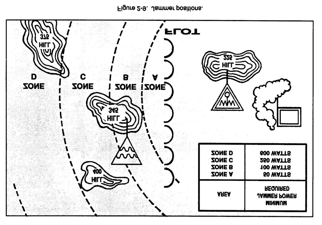
17 COMPUTE JAMMING DATA AND TASK ASSETS In step 6 (Figure 2-7), the TCAE uses the personnel (Figure 2-8, page 2-10). The TCAE s technical data listed in step 5 to compute the efforts conform to the requirements initially minimum jammer power output required for provided by the G3. jamming to be effective. This means that the jammer must be capable of producing at least this In steps 5 and 6, we have entered some of the amount of power output for the jamming mission data available from the enemy electronic order of to be effective. The same data can also be used to battle. For example, in step 5, we indicated that compute the maximum distance the jammer the radio station associated with the first priority location can be located from the target receiver target (the 231st Reconnaissance Battalion) location based on the jammer s maximum power transmits on megahertz. The alternate output. This same information, plus target frequency is unknown. This radio station uses the priorities and jamming on-off times, are a part of call sign AK17. Its transmitter radiates 20 watts the multiple asset tasking message sent to the of power with a 25 kilohertz bandwidth from a jamming assets. vertically polarized whip antenna. The whip antenna is omnidirectional. The TCAE has The jamming computations are further refined by calculated that 100 watts of power are needed to successive planning and directing by the TCAE jam the target receiver from coordinates 2-9
18 EZ (Hill 345). This calculation was made using the Electronic Warfare Jamming Calculator, GTA (see appendix). The various zones are calculated based on different jammer outputs using the GTA In step 6, we calculated that the jammer would have to be on Hill 345 in Zone B to be effective. Figure 2-9 shows that the battlefield has been cross-referenced and assigned zones for locating the jamming teams. Assigning zones also provides greater flexibility to the jamming teams and permits them to adapt to local conditions and restrictions. In the remarks block of Figure 2-7, we identified the ON-OFF control frequency. This frequency must be monitored by the jamming teams to facilitate positive control so jammers can be turned on and off for careful synchronization with other battlefield systems (for example, artillery preparatory fire, a diversion, or a deception operation) or if unexpected problems arise (for example, jamming a frequency used by a medical evacuation helicopter). We have discussed the sequence of actions required by several different echelons when integrating jamming into combat operations. It is important to understand the relationships that take place among the tacticians (as the managers), technicians, and operating elements. The G3 or S3 implements the commander s guidance by integrating jamming with the rest of the battle plan. 2-10
19 2-11
20 CHAPTER 3 Planning the Jamming Operation An artillery commander s fire control element performs many geometric calculations prior to executing a fire mission. These calculations are necessary to bring steel effectively on the target. The jamming mission planner must also perform geometric calculations to bring fire effectively on the target receiver through electromagnetic energy (electromagnetic steel). The jamming mission planner determines the minimum jammer power output required to jam the target receiver effectively. When an excess amount of jamming power is radiated into the air, it is easier for the enemy s DF equipment to intercept and locate the friendly jammer. For the jamming team to accomplish its mission, the mission plainer must determine the distance between the jamming team s location and the target receiver s location. A proposed jamming mission must be carefully evaluated to determine the proper deployment of the jamming team. Distances between the enemy transmitter location and the target receiver location, and IMPORTANCE OF JAMMING between the friendly jammer location and the target receiver location, are two of the critical considerations for jamming team placement. Each jamming team deployment is different. Therefore, constant evaluation of proposed jamming targets is necessary. Terrain is important because line of sight (LOS) is necessary between the jammer s location and the target receiver s location. The enemy can be expected to use terrain to gain an advantage. The type of jammer to be employed is another consideration because some jamming systems have a different power output than others. PLANNED Planned jamming requires the greatest amount of detail; for example, identifying the unit, the location, and the time window for the mission. It JAMMING must be totally synchronized with fire support and maneuver to achieve maximum results. Planned jamming missions can engage a target 3-1
21 simultaneously with fire, or singularly engage lower priority targets simultaneously with fire on higher priority targets. The electronic warfare tasking list (EWTL) can and should list specific targets and times to guide jamming so all targets, regardless of the jamming method used, can be specified in the EWTL. Planned jamming missions could be integrated with fire missions using a field artillery target list work sheet and a scheduling work sheet (Figures 3-1 and 3-2). A planned mission can be used in a direct offensive, a supporting offensive, or a deceptive role. In the direct offensive role, the mission would be targeted against the unit being attacked. A supporting offensive role would consist of jamming those enemy units capable of reinforcing their point of attack. A deceptive jamming mission can consist of jamming against one enemy unit prior to attacking a different enemy unit. The type of role or mission chosen depends on the tactical situation, the degree of knowledge of the enemy situation, the availability of assets, and the objective of the tactical mission. Planned missions can be further divided into scheduled and on-call missions. Scheduled Mission The scheduled mission, on a completed scheduling work sheet, depicts the enemy s unit, target location, and time that jamming is to be conducted. The time of the jamming mission is synchronized with the time of the fire mission to provide the greatest degree of support to the maneuver unit. 3-2

22 On-Call Jamming On-call jamming is dependent upon the unit and location; however, time cannot be ascertained because it is situationally dependent. Therefore, on-call jamming missions lend themselves to targeting reinforcing or second echelon units. On-call jamming missions should be incorporated as necessary into the master fire support (targeting) plan and the fire support execution matrix. Communications interfaces must be adequate to be able to execute the on-call mission at the appropriate time. Electronic masking, often called screen jamming, is also a planned mission. The purpose of electronic masking is to protect or mask friendly communications by denying the enemy the ability to intercept and locate them. Electronic masking is used when mission requirements necessitate the immediate transmission of critical information, and there is no other way to convey the information. Just as offensive jamming captures the receiver of the enemy, electronic masking captures enemy intercept and DF systems by jamming on the friendly frequency ELECTRONIC MASKING using directional antennas close to the forward line of own troops (FLOT). Electronic masking can best be used to mask the radio signals of friendly reinforcements being moved on line, thus preventing enemy signals intelligence from determining the disposition of the reinforcing unit. Figure 3-3 depicts an electronic masking operation. The enemy s ability to locate a jammer accurately through direction finding is reduced by using two or more jammers for an electronic masking operation. 3-3
23 Standing operating procedures (SOP) jamming means allowing the jamming operator to jam targets upon recognition. The SOP jamming technique is used when it is impossible to compute the jamming-to-signal ratio for effective jamming. The SOP jamming technique requires that the jammer s maximum power output must be used to ensure mission effectiveness; therefore, the jammer s power output cannot be reduced during SOP jamming. In certain situations, even the least amount of power reduction could render the jamming ineffective. Our jamming operations must be able to ensure success when the decision to jam is made. SOP jamming has the following disadvantages, which should be considered prior to its implementation: It does not allow for step-by-step coordination with frequency managers, intelligence collectors, or friendly forces in the jamming mission area of operations. The operator will not know if the jamming equipment location is close enough for the jamming signal to overcome the enemy transmitter signal at the target (enemy) receiver s location, without prior planning. Uncontrolled, high-powered jammers can have a disastrous effect on unwarned and unprepared friendly communications. Maximum jammer power output means maximum electronic visibility and vulnerability to the enemy electronic warfare forces, which could result in the destruction of the friendly jamming asset. SOP JAMMING The two methods for employing the SOP jamming technique are called jam upon recognition and targets of opportunity. In the jam upon recognition method, the operator is tasked to search for enemy targets. As soon as the target is identified, it is jammed. The operator is not tasked to jam specific targets at specific times. Under emergency conditions there is no time to plan and coordinate the jamming effort. The targets of opportunity method is used against specific enemy units placed in priority. This method occurs after the targeting process is completed. The G3 or S3 organizes specific enemy targets in a priority order based on the input from the EWS and the fire support coordinator. The TCAE s ECM planning section determines when to jam each target based on the distinguishing traits of the target s communications. Each communications jamming team receives the SOP target jamming list. The list contains target call signs, type of traffic, and frequencies. The communications jamming teams are authorized to jam each target according to the instructions on the SOP target jamming list. The SOP jamming schedule is neither time nor location oriented. Jamming can be performed as jam upon recognition based on tasking requirements and target activity or targets of opportunity, which requires no tasking and is based solely on target activity. Remember, the jammer s maximum power output is used, and commanders must be made aware of the disadvantages of SOP jamming. SURGICAL VERSUS SIGNAL INITIATED JAMMING Planned, on-call, and SOP jamming are the forms signal which makes it difficult for the enemy of jamming referred to as surgical jamming. operator to know if he is being jammed. Signal The surgical jamming technique interrupts the initiated jamming (SIJ) is the jamming of target signal using a continuous wave jamming frequencies programmed into the jammer and 3-4
24 they are automatically jammed as they become active. As a result, a communications check could be jammed and tip off the jamming effort. SIJ increases the chance of fratricide, since the programmed frequency would be jammed regardless of whether it is friendly or enemy. In addition, SIJ bypasses the decision process to jam or listen. SIJ is effective only when the operator can verify that the transmission should be jammed. Surgical jamming is the most effective and is desired over SIJ. Also, the jammer s maximum power output is very important to the success of surgical jamming, when the jamming-to-signal ratio cannot be computed. HIGH POWERED COMMUNICATIONS High powered communications consist of using the jammer as the communications equipment to when communications are mandatory, high powered communications will overcome either increase the power output for friendly natural (static) or intentional (enemy ECM) communications. At critical points of the battle, interference. FUNCTIONS OF MISSION PLANNING Planning the jamming mission in response to specific tactical operations consists of many functions. These functions include - Target isolation. Resource selection. Mission analysis. Effective jamming. Terrain analysis. Target Isolation Upon receipt of a jamming mission requirement, the jamming mission planner obtains target data by searching the enemy electronic order of battle, electronic warfare support measures, and other files. As information on the potential target is checked, frequency parameters are reviewed to determine if they conflict with restricted frequencies. Conflicts are identified and reported to the command establishing the restriction, who is responsible for resolving the conflicts. Unresolved restrictions are noted and added to the target files as restricted frequencies until they are resolved. Resource Selection The next step is to compare the jamming mission with available resources. Information on the type, number, location, and status of friendly jammers is required to effectively assign the mission. The multiple asset status report provides the status of the major assets to the asset manager. Jamming mission requirements that cannot be satisfied by organic direct support capabilities require support from a higher echelon. Mission Analysis The mission planner conducts a detailed analysis of the actual target network based on his geometric calculations, which indicates that the mission has a high probability of success. Analysis isolates the expected pattern of activity and structure for the various jamming operation phases being planned and establishes the engagement methods and timing for maximum target degradation. The multiple asset effectiveness report provides mission effectiveness data from the jammer to the asset mission manager. 3-5
25 The type and number of jamming resources required are examined to ensure that those selected are capable of accomplishing the planned mission. If required, any additional jamming resources needed are identified and requested from the supporting MI unit, Coordination, logistics, and communication problems are identified and procedures for their resolution are established. The multiple asset tasking message is then prepared and passed to the appropriate jamming team. Effective Jamming If the jamming-to-signal ratio for FM signals is large enough (or larger), jamming will be effective. If the jamming-to-signal ratio is too small, then jamming will not be effective (see jamming formulas in the appendix). Effective jamming disrupts, delays, or prevents the effective use of communications by the enemy. The jammer should, ideally, radiate only the amount of power output necessary (minimum jammer power output required) to interfere with the reception of the enemy transmitter signal in the target receiver. Jamming is most effective when it interferes with the enemy s communications without disclosing its presence. The jammer s power output must electronically capture the target receiver (Figure 3-4). Capture occurs when the strength of the friendly jammer s signal is stronger than the enemy transmitter s signal in the target receiver. In this situation, the frequency modulated receiver will be captured by the friendly jamming signal causing the target receiver to reject the weaker enemy transmitter signal. 3-6
26 Terrain Analysis An analysis of the terrain features between the jammers location and friendly units is necessary to prevent inadvertent jamming of friendly communications. Jamming sites should be located UNDERSTANDING JAMMING where they can take advantage of any terrain features that could reduce or block the jamming frequency from interfering with friendly communications. To understand jamming, consider the following situation: The operation plan identifies the enemy's COP and the associated communications as priority targets for jamming. The COP has located our battalion task force (BTF) and is passing this information to the advance guard battalion (AGB) (Figure 3-5). There is no inteeference with their communications. The AGB operator is able to hear and copy all of the COP s transmissions. 3-7
27 Identifying the Target Intercept positions have identified the COP and AGB frequency and intercepted the link s transmissions. DF operations provided a general location for both stations. The emitter locations are given to the TCAE, where the jamming mission is planned. The mission planner determines the minimum jammer power output required to jam the COP and AGB communications as well as a location to deploy the friendly jammer (Figure 3-6). Tasking the Mission This information is forwarded, using secure communications, to the appropriate jamming team. Upon receiving the tasking, the jamming equipment is deployed to the designated location. The jamming equipment operator then Tunes the jammer to proper frequency. Makes the necessary adjustments based on the multiple asset tasking message. Jams the target receiver as directed. 3-8
28 Accomplishing the Mission This mission successfully disrupted the enemy communication and delayed passage of the information. Therefore, the mission planner computed the correct minimum jammer power output required for this mission and the enemy s target receiver was captured. Jamming interfered with receipt of the message and required the AGB operator to ask for repeats of the message. Determining the Power Output It is very difficult, if not impossible, to determine the exact jammer power output required to electronically capture a target receiver. The criteria for determining the minimum jammer power output required to capture a receiver is not universally accepted. Before determining the minimum amount of jammer power output required for a given tactical situation, the mission planner must understand that groundbased jamming is very complex. In free space, some of these variables are not important. However, on the ground they can become critical. Some of the variables which can cause attenuation of radio waves are terrain, ground conductivity, vegetation, and weather (Figure 3-7). 3-9
29 CHAPTER 4 Training Two categories of training are required to prepare the soldier to operate a jammer in combat: resident and in-unit training. Voice interceptors (military occupational specialty 98G) must be skilled in communications intercept to recognize the target signal. While training in most MI disciplines results in the awarding of a military occupational specialty, soldiers qualified in the skill of jamming receive an additional skill identifier of K3. RESIDENT TRAINING Resident training is currently taught during the training exercise is conducted at the end of each Communications Electronic Warfare Operations course. During the field training exercise the Course (CEWOC). This training consists of student is evaluated for knowledge of installing and operating ECM, electronic warfare Electronic warfare skills. support measures, and communications Perimeter defense. equipment. Training is conducted in ECM and Nuclear, biological, and chemical operations. electronic warfare support measures missions against those targets unique to the student s Survival skills. tactical duty assignment. A simulated field IN-UNIT TRAINING In-unit training refines skills learned during and survive. Survival is critical to the continued resident training. It combines technical skills success of a unit. Therefore, in-unit training must with survival skills. This combination ensures emphasize the survival principles. It must stress that the unit can conduct jamming operations the importance of reducing the amount of power 4-1
30 and time a jammer s transmitter is keyed and that you transmit only with the amount of power needed to accomplish the mission. Using only the amount of power necessary to effectively jam and keying the jammer s transmitter in short bursts reduces the probability of detection by enemy intercept and DF equipment. In-unit training should provide a means of measuring and controlling these two jamming principles. This is possible when in-unit training is designed to allow soldiers to practice their jamming skills. Unit trainers are challenged to make jamming training as realistic as possible. Realism is achieved when the jamming mission planner and the jamming equipment operator are trained in a simulated combat situation. This setting allows the effectiveness of the mission planner to be measured. The successful execution of the jamming mission indicates that the mission planner is effective. Successful mission planning and execution during in-unit training provide the technical and tactical skills needed in combat. 4-2
31 APPENDIX Jamming Calculations The three methods used in jamming calculations involve jamming formulas, the GTA , and the JAMPOT fan. The jamming formulas are used to determine the jamming power output and jammer distance to target. Calculations are made manually. The GTA results require the aid of the electronic warfare jamming calculator. Likewise, the results achieved with the JAMPOT fan require the aid of a JAMPOT fan template. ABBREVIATIONS AND FORMUL4S Understanding the abbreviations and jamming factors that impact on effective jamming formulas presented makes jamming mission computation easier. When planning a jamming missions. Once these factors are determined, they are used to select the proper jamming mission, it is necessary to make a thorough and reasonable appraisal of the significant technical equipment to conduct the jamming mission. A-1
32 Abbreviations Study the following abbreviations before reading further. They will be used often, and a little time spent on them now may preclude the necessity of constantly turning the pages to understand what they mean. Additionally, as you use these formulas, ensure you are using the numbers in the proper units (for example, power in watts, distance in kilometers, and elevation in feet). P j = P t = H j= Minimum amount of jammer power output required in watts (read on power output meter of the jammer). Power output of the enemy transmitter in watts. Elevation of the jammer location above the sea level. NOTE: The elevation of the jammer location and the enemy transmitter location does not include the height of the antenna above the ground or the length of the antenna. It is the location elevation above the sea level. H t= Dj = D t= K = n = Elevation of the enemy transmitter location above the sea level. Jammer location-to-target receiver location distance in kilometers. Enemy transmitter location-to-target receiver location distance in kilometers. Number 2 for jamming frequency modulated receivers (jammer tuning accuracy). Terrain and ground conductivity factor. 5= 4= 3= 2= Very rough terrain (rocky mountains or desert) with poor ground conductivity. Moderately rough terrain (rolling to high hills, forested farmland) with fair to good ground conductivity. Rolling hills (farmland type terrain) with good ground conductivity. Level terrain (over water, sea, lakes, and ponds) with good ground conductivity. Jamming Formulas Jamming formulas provide the tools needed to compute the jamming power output and jammer distances. The formulas presented here are based on a tactical situation where the enemy transmitter-receiver link and jammer-enemy receiver link are operating over moderately rough terrain with no high hills between the two locations. The enemy transmitter and friendly jammer locations are at approximately the same elevation above the sea level (difference is less than 10 meters). When the terrain features differ by more than 10 meters between the enemy transmitter and friendly jammer locations, the mission planner must factor this difference into his calculations. FORMULA 1 Formula 1 (Figure A-1) is used to compute the minimum jammer power output that is required (the least amount) to effectively jam the target receiver. A-2
33 EQUIPMENT PARAMETERS The equipment parameters of friendly and enemy equipment are needed to solve this formula. The parameters of friendly equipment can be obtained from the technical manuals written for the equipment. Technical intelligence publications on enemy communications systems provide similar data and can be obtained from the G2. When information is not available on enemy communications systems, it may become necessary to estimate the parameters to reach a solution. In the following tactical situation, the essential parameters needed to compute formula 1 are given as: f = Dt= Dj = Pt = Pj = H t = Hj = K= n = Frequency (37.5 megahertz). Enemy transmitter location-to-target receiver location distance in km (9 km). Jammer location-to-target receiver location distance in km (17 km). Power output of the enemy transmitter in watts (5 watts). Minimum amount of jammer power output required in watts (solve). Elevation of the enemy transmitter location above the sea level in meters (385 meters). Elevation of the jammer location above the sea level in meters (388 meters). FM jammer tuning accuracy (2). Terrain and ground conductivity factor (4). Substitute the parameters in formula 1 using the steps shown in Table A-1 on page A-4 to solve for Pj. A-3
34 A-4
35 The selected jammer must be able to produce and use 125 watts of power output to overcome the enemy's transmitter signal at the target receiver location. Less than watts of power will not be effective. If more than 125 watts are used, jamming will still be effective. The 125 watts represents the minimum power output reading for effective jamming using a whip antenna in this tactical situation. The 62.5 watts is the minimum power for the same problem when using the jammer s log periodic array (LPA) antenna. A-5
36 FORMULA 2 Formula 2 (Figure A-2) is used to compute the maximum distance that a jammer s location can be from the target receiver location and still be effective. Use 1,500 watts as the maximum jammer power output in this tactical situation. Substitute the rest of the numerical values from formula 1 for the parameters in formula 2. Use the steps in Table A-2 to find the solution for the maximum jammer location-to-target receiver location distance. A-6
37 A-7
38 A-8
39 A-9
40 TERRAIN AND GROUND CONDUCTIVITY FACTORS As previously mentioned, the attenuation of radio waves is subject to terrain and ground conductivity factors (n). Table A-3 on page A-11 is used to compute the minimum jammer power output and maximum jammer location-to-target receiver location distance. Multiply the watts from Table A-3 by the power output of the enemy s transmitter to obtain the minimum power output. The factor of n equals 5 is used for very rough terrain (deserts or mountains) with poor ground conductivity. The table is a matrix. The left column (reading down from 0.5 to 10.0) is the jammer location-to-target receiver location distance in kilometers. The top line of numbers (0.5 to 5.0) is the enemy transmitter-to-target receiver location distance in kilometers. The internal numbers (1 through 26.4K) are expressed in watts or kilowatts (K equals. multiplication by 1,000). To use the table, take the kilometers reading from the left column and the kilometers reading from the top line and find where they intersect. For example, if the jammer is 1.5 kilometers from the target and the enemy transmitter is 0.5 from the target, the factor is 486 watts. This means if the enemy transmitter uses only 1 watt, the jammer must use at least 486 watts to be successful under these conditions. The factor of 486 is achieved by dividing the jammer location-to-target receiver distance (1.5) by the enemy transmitter location-to-target receiver distance (0.5). The result (3) is first A-10
41 raised to the fifth power (243) and then doubled digits to the right of the decimal are used, and (486). When fractions are encountered as result the fraction is not rounded off. Therefore, for the of division (for example 8.5 km divided by 4.5 purpose of finding then factor, is viewed kilometers equals ), only the first two as A-11
42 Table A-4 is similar to Table A-3, but the internal numbers are changed. They are based a factor of n = 4. After dividing the jammer-t.o-target receiver distance by the enemy transmitter location-to-target receiver distance, the result is raised to the fourth power and then doubled. A-12
43 Table A-5 is based on a factor of n = 3. After dividing the jammer-to-target receiver distance by the enemy transmitter location-to-target receiver distance, the result is raised to the third power and doubled. A-13
44 Table A-6 is based on a factor of n = 2. After dividing the jammer-to-target receiver distance by the enemy transmitter location-to-target receiver distance, the result is raised to the second power and doubled. A-14
45 Tables A-3 through A-6 are reliable under the following conditions: Elevation of the jammer location above the sea level is approximately the same as the elevation of the enemy transmitter location (less than 10 meters difference). Power values obtained from the tables match the reading on the jammer s power output meter. (Antenna loss and voltage standing wave ratio have been taken into account.) Power values are used with the jammer s whip antenna. Jammer location must have a reasonable LOS propagation path to the target receiver location with no high hills between the two locations. Jammer is used against frequency modulated voice communications in the VHF range. The exceptions to the above conditions are If the elevation of the jammer location and the enemy transmitter location difference is 10 meters or more. If the LPA antenna is used instead of a whip antenna, the power indicated must be divided by 2. ELEVATION RATIO AND MULTIPLICATION FACTORS Table A-7, page A-16, is used to convert the minimum jammer power output value obtained from Table A-3. It is used when the elevation difference of the jammer location and the enemy transmitter location is 10 or more meters. Determine the Elevation Ratio To convert the minimum jammer power output from Table A-3, the elevation ratio must be determined. To do this, divide the jammer location elevation by the enemy transmitter location elevation. The jammer location-to-enemy transmitter location elevation ratios are listed in the left column in Table A-7. Rounding down, find the next lower elevation ratio number which is closest to your computed ratio. Always round the ratio down to the next lower ratio number in the table to ensure that there will be sufficient power output for effective jamming. The figure to the right of the numbers is the elevation multiplication factor. Multiply the minimum jammer power output value from Table A-3 by the elevation multiplication factor from Table A-7. The result is the final minimum jammer power output necessary for effective jamming, in this location elevation ratio situation. Determine the Multiplication Factor As an example, we will use the minimum jammer power output from Table A-3 of 64 watts. The elevation of the jammer location is 435 meters and the elevation of the enemy transmitter location is 557 meters. Determine the location elevation ratio by dividing the jammer location elevation (435 meters) by the enemy transmitter location elevation (557 meters). The result is the fraction.78. Round the fraction down to the nearest number on Table A-7 (.75). Read to the right of.75 and the multiplication factor is 1.8. Next, multiply the jammer power output selected from Table A-3 (64 watts) by the multiplication factor of (1.8). The answer is or 116. The 116 watts is adjusted into a power output figure used in computing the final jammer power output which can be used for effective jamming. A-15
46 A-16
47 MINIMUM JAMMER POWER OUTPUT REQUIREMENT Table A-8 is a step-by-step exercise to determine the minimum jammer power output for effective jamming using Table A-3 (desert terrain) with the following parameters: Enemy transmitter-to-target receiver distance Jammer-to-target receiver distance (18 km). Enemy transmitter power output (1.5 watts). Jammer location elevation above the sea level (85 meters). Enemy transmitter location elevation above the sea level (68 meters). A-17
48 A-18
49 MAXIMUM JAMMER DISTANCE The following parameters are provided to compute the maximum distance a jammer location can be from the target receiver location (Table A-10): Enemy transmitter-to-target receiver distance (3 km). Enemy transmitter power output (2 watts). Jammer power output (550 watts). Jammer location elevation above the sea level (385 meters). Enemy transmitter location elevation above the sea level (386 meters). A-19
50 A-20
51 THE GTA CALCULATOR The Electronic Warfare (EW) Jamming power output required for effective jamming. Calculator (Figure A-3), provides a quick and This calculator can be used with any size map. easy method to calculate the minimum jammer A-21
52 GTA Calculator Effectiveness The GTA calculator is effective under the following conditions and parameters when Frequency modulated voice communications in the VHF range are used. The enemy communication transmitter power output is known. The enemy communication transmitter-to-target receiver distance in kilometers is known. The jammer location-to-target receiver location distance in kilometers is known. The jammer location, enemy transmitter location, and target receiver location are known. All location elevations are measured from the sea level. Power output values calculated using the GTA calculations are for the jammer s whip antenna. (If the LPA antenna is used, divide the final calculated power output by 2.) The minimum jammer power output calculated (in watts) must be read on the jammer s power output meter. Jammer location must have a reasonable LOS propagation path to the target receiver s location with no high hills between the two locations. Minimum Jammer Power Output Required for Effective Jamming Use the GTA calculator shown in Figure A-3 to determine the minimum jammer power output required for effective jamming. Calculations include the minimum power for the whip antenna and the LPA antenna (Table A-11). A-22
53 A-23
54 A-24
55 A-25
56 The jammer must be capable of producing at least jammer site can be from the target receiver and 114 watts with the whip antenna or 57 watts for still jam effectively. Use the GTA the LPA antenna for jamming to be effective. If a calculator to find the maximum power output of higher power value is used, the jammer will still the jammer. be effective. Using any power output less than these values will not effectively jam the target receiver for this example. Compute the Maximum Distance the Jammer Can Be From the Target Receiver Perform the following steps in Table A-12 to calculate the maximum distance the selected A-26
57 A-27
58 A-28
59 A-29
60 GTA Calculator Work Sheet The GTA calculator work sheet (Figure A-4) is to be used with the GTA calculator when computing the minimum jammer power output required for a given jamming situation. Table A-13, page 32, explains how to fill in the work sheet. A-30
61 A-31
62 A-32
63 Figure A-5 shows a completed GTA calculator work sheet. The elevation difference reflects data from step 2B. A-33
64 THE JAMPOT FAN The JAMPOT fan (Figure A-6) provides another developed for a map scale of 1:50,000. It can also method for measuring distances needed to be used for a map scale of 1:100,000 by calculate the required jamming power output. It multiplying the jammer-to-target receiver is designed to be used with Table A-14, page A-35. distance by two. The JAMPOT fan is an overlay template A-34
65 A-35
66 JAMPOT Fan Effectiveness The JAMPOT fan is effective only under the following conditions and parameters: It must be used for frequency modulated voice, amplitude modulated voice, or continuous wave communications in the VHF range. The enemy target transmitter power output must be known. The enemy transmitter-to-target receiver distance in kilometers must be known. The jammer location must be known. The jammer must be located at the same elevation above the sea level or higher than the enemy target transmitter. A whip antenna must be used with the power output values in Table A-14. (If the LPA antenna is used, divide the values by two.) The jammer power output values obtained from Table A-14 must be read on the jammer s power output meter. The jammer location must have a reasonable LOS - propagation path to the target receiver location with no high hills between the two locations. Using the JAMPOT Fan Table A-15 is a step-by-step explanation of how to use the JAMPOT fan. A-36
67 A-37
68 A-38
69 A-39
70 A-40

71 Glossary ACRONYMS AND ABBREVIATIONS A acq acquisition ACR armored cavalry regiment ADA air defense artillery AGB advance guard battalion AM amplitude modulated ant antenna AR Army regulation az azimuth B bn battalion BTF battalion task force btry battery bw bandwidth C C³CM command, control and communications countermeasures CDR commander CEWOC Communications Electronic Warfare Operations Course COP command and observation post c/s call sign CW continuous wave D DA Department of the Army degree(s) DF direction finding dist distance DSSB double single sideband Glossary-1
3 Planning the Jamming Operation
 CHAPTER 3 Planning the Jamming Operation An artillery commander s fire control element performs many geometric calculations prior to executing a fire mission. These calculations are necessary to bring
Jamming Calculations
 APPENDIX Jamming Calculations The three methods used in jamming calculations involve jamming formulas, the GTA 30-6-5, and the JAMPOT fan. The jamming formulas are used to determine the jamming power output
Chapter 2 Threat FM 20-3
 Chapter 2 Threat The enemy uses a variety of sensors to detect and identify US soldiers, equipment, and supporting installations. These sensors use visual, ultraviolet (W), infared (IR), radar, acoustic,
CONVERGENCE BETWEEN SIGNALS INTELLIGENCE AND ELECTRONIC WARFARE SUPPORT MEASURES
 Technical Sciences 327 CONVERGENCE BETWEEN SIGNALS INTELLIGENCE AND ELECTRONIC WARFARE SUPPORT MEASURES Zsolt HAIG haig.zsolt@uni nke.hu National University of Public Service, Budapest, Hungary ABSTRACT
Chapter 4. Meaconing, Intrusion, Jamming, and Interference Reporting
 Chapter 4 FM 24-33 Meaconing, Intrusion, Jamming, and Interference Reporting 4-1. Introduction a. Meaconing, intrusion, and jamming are deliberate actions intended to deny an enemy the effective use of
Leveraging Digital RF Memory Electronic Jammers for Modern Deceptive Electronic Attack Systems
 White Paper Leveraging Digital RF Memory Electronic Jammers for Modern Deceptive Electronic Attack Systems by Tony Girard Mercury systems MaRCH 2015 White Paper Today s advanced Electronic Attack (EA)
EC312 Lesson 20: Electronic Warfare (3/20/14)
") Objectives: EC312 Lesson 20: Electronic Warfare (3/20/14) (a) Define and provide an example of Electronic Warfare (EW) and its three major subdivisions: Electronic Protection (EP), Electronic Support(ES)
Objectives: EC312 Lesson 20: Electronic Warfare (3/20/14) (a) Define and provide an example of Electronic Warfare (EW) and its three major subdivisions: Electronic Protection (EP), Electronic Support(ES)
During the next two months, we will discuss the differences
 EW 101 ES vs. SIGINT By Dave Adamy 42 The Journal of Electronic Defense January 2011 During the next two months, we will discuss the differences between Electronic Support (ES) systems and Signals Intelligence
DISTRIBUTED COHERENT RF OPERATIONS
 DISTRIBUTED COHERENT RF OPERATIONS John A. Kosinski U.S. Army RDECOM CERDEC AMSRD-CER-IW-DT Fort Monmouth, NJ 07703, USA Abstract The concept of distributed coherent RF operations is presented as a driver
Game Turn 11 Soviet Reinforcements: 235 Rifle Div can enter at 3326 or 3426.
 General Errata Game Turn 11 Soviet Reinforcements: 235 Rifle Div can enter at 3326 or 3426. Game Turn 11 The turn sequence begins with the Axis Movement Phase, and the Axis player elects to be aggressive.
SQUAD/PLATOON COMMUNICATIONS
 APPENDIX D SQUAD/PLATOON COMMUNICATIONS Section I. TYPES OF COMMUNICATIONS D-1. GENERAL Squads and platoons must be able to communicate to control and coordinate movement and fires, send and receive instructions,
TACTICAL SINGLE-CHANNEL RADIO COMMUNICATIONS TECHNIQUES
 Field Manual No. 24-18 FM 24-18 HEADQUARTERS DEPARTMENT OF THE ARMY Washington, D.C. 30 September 1987 TACTICAL SINGLE-CHANNEL RADIO COMMUNICATIONS TECHNIQUES TABLE OF CONTENTS PREFACE iv CHAPTER 1 INTRODUCTION
Real-Time Spectrum Monitoring System Provides Superior Detection And Location Of Suspicious RF Traffic
 Real-Time Spectrum Monitoring System Provides Superior Detection And Location Of Suspicious RF Traffic By Malcolm Levy, Vice President, Americas, CRFS Inc., California INTRODUCTION TO RF SPECTRUM MONITORING
Portable Wargame. The. Rules. For use with a battlefield marked with a grid of hexes. Late 19 th Century Version. By Bob Cordery
 The Portable Wargame Rules Late 19 th Century Version For use with a battlefield marked with a grid of hexes By Bob Cordery Based on some of Joseph Morschauser s original ideas The Portable Wargame Rules
A MINI REVIEW ON RADAR FUNDAMENTALS AND CONCEPT OF JAMMING
 DOI: http://dx.doi.org/10.26483/ijarcs.v8i9.5195 Volume 8, No. 9, November-December 2017 International Journal of Advanced Research in Computer Science RESEARCH PAPER Available Online at www.ijarcs.info
Frontier/Modern Wargames Rules
 Equipment: Frontier/Modern Wargames Rules For use with a chessboard battlefield By Bob Cordery Based on Joseph Morschauser s original ideas The following equipment is needed to fight battles with these
Introduction to Electronic Defence EEE5106S
 Introduction to Electronic Defence EEE5106S P.F. Potgieter and J.D. Vlok September 29, 2011 Contents 1 Introduction 2 2 Lecturer Information 2 3 Course Objectives and Study Themes 3 3.1 Theme 1: The History
Solitaire Rules Deck construction Setup Terrain Enemy Forces Friendly Troops
 Solitaire Rules Deck construction In the solitaire game, you take on the role of the commander of one side and battle against the enemy s forces. Construct a deck, both for yourself and the opposing side,
FAQ WHAT ARE THE MOST NOTICEABLE DIFFERENCES FROM TOAW III?
 1 WHAT ARE THE MOST NOTICEABLE DIFFERENCES FROM TOAW III? a) Naval warfare has been radically improved. b) Battlefield Time Stamps have radically altered the turn burn issue. c) The User Interface has
RANDOM MISSION CONTENTS TAKING OBJECTIVES WHICH MISSION? WHEN DO YOU WIN THERE ARE NO DRAWS PICK A MISSION RANDOM MISSIONS
 i The 1 st Brigade would be hard pressed to hold another attack, the S-3 informed Bannon in a workman like manner. Intelligence indicates that the Soviet forces in front of 1 st Brigade had lost heavily
Napoleon s Triumph. Rules of Play (draft) Table of Contents
 Table of Contents") Rules of Play (draft) Table of Contents 1. Game Equipment... 2 2. Introduction to Play... 2 3. Playing Pieces... 2 4. The Game Board... 2 5. Scenarios... 3 6. Setting up the Game... 3 7. Sequence of Play...
Rules of Play (draft) Table of Contents 1. Game Equipment... 2 2. Introduction to Play... 2 3. Playing Pieces... 2 4. The Game Board... 2 5. Scenarios... 3 6. Setting up the Game... 3 7. Sequence of Play...
Technical Requirements for Land Mobile and Fixed Radio Services Operating in the Bands / MHz and / MHz
 Issue 5 November 2013 Spectrum Management and Telecommunications Standard Radio System Plan Technical Requirements for Land Mobile and Fixed Radio Services Operating in the Bands 806-821/851-866 MHz and
LA6NCA LA6NCA
 Panzer IV communication system. From US INTELLIGENCE BULLETIN December 1942 A captured German training pamphlet contains the following information regarding the duties of the crew of a Mark IV tank, and
Passive Radars as Sources of Information for Air Defence Systems
 Passive Radars as Sources of Information for Air Defence Systems Wiesław Klembowski *, Adam Kawalec **, Waldemar Wizner *Saab Technologies Poland, Ostrobramska 101, 04 041 Warszawa, POLAND wieslaw.klembowski@saabgroup.com
 UNIT I FUNDAMENTALS OF ANALOG COMMUNICATION Introduction In the Microbroadcasting services, a reliable radio communication system is of vital importance. The swiftly moving operations of modern communities
Department of Operations Telecommunications Division
 COAST GUARD AUXILIARY HF TELECOMMUNICATIONS PROGRAM POLICIES AND PROCEDURES Section A. Auxiliary High Frequency (HF) Program A.1 Introduction: The Coast Guard Auxiliary High Frequency telecommunications
Maida 1806: Stuart vs. Reynier
 Table of contents. 1.0 Introduction... 2.0 Components... 3.0 Gameplay... 4.0 Leaders... 5.0 Infantry in Column... 6.0 Infantry in Line... 7.0 Square... 8.0 Skirmish order... 9.0 Cavalry... 10.0 Artillery...
DRS Electronic Warfare Operational Awareness Simulation/Support and Diagnostics
 DRS Electronic Warfare Operational Awareness Mission Scenario Generation and Simulation Author: Dr. Bruce Holley BSc MSc PhD CEng CPhys MInstP MIET Eur Ing Head of Air Systems LOB, DRS (UK) DRS ELECTRONIC
Chapter 4 FH Networks
 Chapter 4 FH Networks 4-1. FH Variables a. SINCGARS hops or changes frequencies about 100 times per second. The radio uses digital processing to control the hopping sequence and the pattern so that the
RFeye Arrays. Direction finding and geolocation systems
 RFeye Arrays Direction finding and geolocation systems Key features AOA, augmented TDOA and POA Fast, sensitive, very high POI of all signal types Capture independent of signal polarization Antenna modules
Fog of War and Intelligence Planning in Wargaming. Brant Guillory BayonetGames
 Fog of War and Intelligence Planning in Wargaming Brant Guillory BayonetGames Who Am I Head Boardgame Developer & Game Commando, BayonetGames Deputy Brigade S-2, 37th Infantry Brigade Playtest Coordinator
WARHAMMER 40K COMBAT PATROL
 9:00AM 2:00PM ------------------ SUNDAY APRIL 22 11:30AM 4:30PM WARHAMMER 40K COMBAT PATROL Do not lose this packet! It contains all necessary missions and results sheets required for you to participate
Electronic Warfare Training in the Pacific Northwest
 Electronic Warfare Training in the Pacific Northwest Mission of the U.S. Navy To maintain, train and equip combat-ready naval forces capable of winning wars, deterring aggression and maintaining freedom
ARCHIVED REPORT. ULQ-19(V)/RACJAM - Archived 6/97
/RACJAM - Archived 6/97") Land & Sea-Based Electronics Forecast ARCHIVED REPORT For data and forecasts on current programs please visit www.forecastinternational.com or call +1 203.426.0800 ULQ-19(V)/RACJAM - Archived 6/97 Outlook
Land & Sea-Based Electronics Forecast ARCHIVED REPORT For data and forecasts on current programs please visit www.forecastinternational.com or call +1 203.426.0800 ULQ-19(V)/RACJAM - Archived 6/97 Outlook
CONTENTS INTRODUCTION Compass Games, LLC. Don t fire unless fired upon, but if they mean to have a war, let it begin here.
 Revised 12-4-2018 Don t fire unless fired upon, but if they mean to have a war, let it begin here. - John Parker - INTRODUCTION By design, Commands & Colors Tricorne - American Revolution is not overly
Improving Performance through Superior Innovative Antenna Technologies
 Improving Performance through Superior Innovative Antenna Technologies INTRODUCTION: Cell phones have evolved into smart devices and it is these smart devices that have become such a dangerous weapon of
CONFEDERACY GAME OVERVIEW. Components 60 Troop tiles 20 double sided Order/Wound Tokens 2 player aids 6 dice This ruleset
 MODERN #1 CONFEDERACY GAME OVERVIEW Pocket Battles is a series of fast and portable wargames. Each game comes with two armies that can be lined up one versus the other, or against any other army in the
An analysis of Cannon By Keith Carter
 An analysis of Cannon By Keith Carter 1.0 Deploying for Battle Town Location The initial placement of the towns, the relative position to their own soldiers, enemy soldiers, and each other effects the
RESEARCH ON METHODS FOR ANALYZING AND PROCESSING SIGNALS USED BY INTERCEPTION SYSTEMS WITH SPECIAL APPLICATIONS
 Abstract of Doctorate Thesis RESEARCH ON METHODS FOR ANALYZING AND PROCESSING SIGNALS USED BY INTERCEPTION SYSTEMS WITH SPECIAL APPLICATIONS PhD Coordinator: Prof. Dr. Eng. Radu MUNTEANU Author: Radu MITRAN
COMPONENT OVERVIEW Your copy of Modern Land Battles contains the following components. COUNTERS (54) ACTED COUNTERS (18) DAMAGE COUNTERS (24)
 ACTED COUNTERS (18) DAMAGE COUNTERS (24)") GAME OVERVIEW Modern Land Battles is a fast-paced card game depicting ground combat. You will command a force on a modern battlefield from the 1970 s to the modern day. The unique combat system ensures
GAME OVERVIEW Modern Land Battles is a fast-paced card game depicting ground combat. You will command a force on a modern battlefield from the 1970 s to the modern day. The unique combat system ensures
APPENDIX B. Anti-satellite Weapons Geoffrey Forden. Laser Attacks against Satellites
 Appendices 75 APPENDIX B Anti-satellite Weapons Geoffrey Forden Laser Attacks against Satellites In the past, both the United States and Russia have considered using lasers in missile defense systems.
GUIDED WEAPONS RADAR TESTING
 GUIDED WEAPONS RADAR TESTING by Richard H. Bryan ABSTRACT An overview of non-destructive real-time testing of missiles is discussed in this paper. This testing has become known as hardware-in-the-loop
A NEW SIMULATION FRAMEWORK OF OPERATIONAL EFFECTIVENESS ANALYSIS FOR UNMANNED GROUND VEHICLE
 A NEW SIMULATION FRAMEWORK OF OPERATIONAL EFFECTIVENESS ANALYSIS FOR UNMANNED GROUND VEHICLE 1 LEE JAEYEONG, 2 SHIN SUNWOO, 3 KIM CHONGMAN 1 Senior Research Fellow, Myongji University, 116, Myongji-ro,
Components Locked-On contains the following components:
 Introduction Welcome to the jet age skies of Down In Flames: Locked-On! Locked-On takes the Down In Flames series into the Jet Age and adds Missiles and Range to the game! This game includes aircraft from
Unit List Hot Spot Fixed
 Getting Started This file contains instructions on how to get started with the Fulda Gap 85 software. If it is not already running, you should run the Main Program by clicking on the Main Program entry
When it comes to generic 25mm Science Fiction skirmish games, there are really only two choices.
 1 of 6 When it comes to generic 25mm Science Fiction skirmish games, there are really only two choices. Stargrunt II, which is a gritty, realistic simulation of near-future combat. And ShockForce, which
Chapter 1 Introduction
 Chapter 1 Introduction 1-1. Army Space Activities a. Tactical satellite (TACSAT) communications is part of a larger group of Army space activities. The Chief of Staff, US Army (CSA) directs all Army space
ARMY COMMANDER - GREAT WAR INDEX
 INDEX Section Introduction and Basic Concepts Page 1 1. The Game Turn 2 1.1 Orders 2 1.2 The Turn Sequence 2 2. Movement 3 2.1 Movement and Terrain Restrictions 3 2.2 Moving M status divisions 3 2.3 Moving
Digi-Wave Technology Williams Sound Digi-Wave White Paper
 Digi-Wave Technology Williams Sound Digi-Wave White Paper TECHNICAL DESCRIPTION Operating Frequency: The Digi-Wave System operates on the 2.4 GHz Industrial, Scientific, and Medical (ISM) Band, which is
ARMOR DIAGRAM ARMOR DIAGRAM. Mech Data. Mech Data BATTLEMECH RECORD SHEET BATTLEMECH RECORD SHEET. Weapons Inventory.
 BATTLEMECH RECORD SHEET Left Torso Head Right Torso ARMOR DIAGRAM Type: HER-2S Hermes II Tonnage: 40 Points: Walking: 6 Running: 9 Weapons Inventory Mech Data Type Location Damage Short Med. Long 1 Autocannon
Legends of War: Patton Manual
 Legends of War: Patton Manual 1.- FIRST STEPS... 3 1.1.- Campaign... 3 1.1.1.- Continue Campaign... 4 1.1.2.- New Campaign... 4 1.1.3.- Load Campaign... 5 1.1.4.- Play Mission... 7 1.2.- Multiplayer...
Headquarters Department of the Army
 ATP 3-09.02 Field Artillery Survey FEBRUARY 2016 DISTRIBUTION RESTRICTION: Approved for public release; distribution is unlimited. This publication supersedes FM 6-2, Tactics, Techniques, and Procedures
Virtual Reality Devices in C2 Systems
 Jan Hodicky, Petr Frantis University of Defence Brno 65 Kounicova str. Brno Czech Republic +420973443296 jan.hodicky@unbo.cz petr.frantis@unob.cz Virtual Reality Devices in C2 Systems Topic: Track 8 C2
FM Transmission Systems Course
 FM Transmission Systems Course Course Description An FM transmission system, at its most basic level, consists of the transmitter, the transmission line and antenna. There are many variables within these
RESERVES RESERVES CONTENTS TAKING OBJECTIVES WHICH MISSION? WHEN DO YOU WIN PICK A MISSION RANDOM MISSION RANDOM MISSIONS
 i The Flames Of War More Missions pack is an optional expansion for tournaments and players looking for quick pick-up games. It contains new versions of the missions from the rulebook that use a different
Technical Requirements for Wireless Broadband Services (WBS) in the Band MHz
 in the Band MHz") Issue 2 June 2010 Spectrum Management and Telecommunications Standard Radio System Plan Technical Requirements for Wireless Broadband Services (WBS) in the Band 3650-3700 MHz Aussi disponible en français
Issue 2 June 2010 Spectrum Management and Telecommunications Standard Radio System Plan Technical Requirements for Wireless Broadband Services (WBS) in the Band 3650-3700 MHz Aussi disponible en français
The Next Generation of Covert Antennas
 The Next Generation of Covert Antennas A New Design Increases Flexibility and Maximizes Performance Harris Corporation TABLE OF CONTENTS Antenna Design Starts with the Radio... 5 How to Evaluate Covert
Lecture 3 SIGNAL PROCESSING
 Lecture 3 SIGNAL PROCESSING Pulse Width t Pulse Train Spectrum of Pulse Train Spacing between Spectral Lines =PRF -1/t 1/t -PRF/2 PRF/2 Maximum Doppler shift giving unambiguous results should be with in
A Thunderbolt + Apache Leader TDA
 C3i Magazine, Nr.3 (1994) A Thunderbolt + Apache Leader TDA by Jeff Petraska Thunderbolt+Apache Leader offers much more variety in terms of campaign strategy, operations strategy, and mission tactics than
Silent Sentry. Lockheed Martin Mission Systems. Jonathan Baniak Dr. Gregory Baker Ann Marie Cunningham Lorraine Martin.
 Silent Sentry Passive Surveillance Lockheed Martin Mission Systems Jonathan Baniak Dr. Gregory Baker Ann Marie Cunningham Lorraine Martin June 7, 1999 6/7/99 1 Contact: Lorraine Martin Telephone: (301)
Exercise 1-5. Antennas in EW: Sidelobe Jamming and Space Discrimination EXERCISE OBJECTIVE
 Exercise 1-5 Antennas in EW: Sidelobe Jamming EXERCISE OBJECTIVE To demonstrate that noise jamming can be injected into a radar receiver via the sidelobes of the radar antenna. To outline the effects of
Sky Satellites: The Marine Corps Solution to its Over-The-Horizon Communication Problem
 Sky Satellites: The Marine Corps Solution to its Over-The-Horizon Communication Problem Subject Area Electronic Warfare EWS 2006 Sky Satellites: The Marine Corps Solution to its Over-The- Horizon Communication
WOLF - Wireless robust Link for urban Forces operations
 Executive summary - rev B - 01/05/2011 WOLF - Wireless robust Link for urban Forces operations The WOLF project, funded under the 2nd call for proposals of Joint Investment Program on Force Protection
SUBJECT: Army Directive (Acquisition Reform Initiative #3: Improving the Integration and Synchronization of Science and Technology)
") S E C R E T A R Y O F T H E A R M Y W A S H I N G T O N MEMORANDUM FOR SEE DISTRIBUTION SUBJECT: Army Directive 2017-29 (Acquisition Reform Initiative #3: Improving the 1. References. A complete list of
S E C R E T A R Y O F T H E A R M Y W A S H I N G T O N MEMORANDUM FOR SEE DISTRIBUTION SUBJECT: Army Directive 2017-29 (Acquisition Reform Initiative #3: Improving the 1. References. A complete list of
Getting Started with Panzer Campaigns: Budapest 45
 Getting Started with Panzer Campaigns: Budapest 45 Welcome to Panzer Campaigns Budapest 45. In this, the seventeenth title in of the Panzer Campaigns series of operational combat in World War II, we are
Tailored Tactical Surveillance
 Mr. Tim Clark Program Manager Special Projects Office At our last DARPATech, the Special Projects Office (SPO) discussed the need for persistent global and theater surveillance and how, by advancing the
CHAPTER 3 MARGINAL INFORMATION AND SYMBOLS
 CHAPTER 3 MARGINAL INFORMATION AND SYMBOLS A map could be compared to any piece of equipment, in that before it is placed into operation the user must read the instructions. It is important that you, as
Open-3.1 Tournament Rules Tournament Scheduling Force Selection Round/Match procedure
 Open-3.1 Tournament Rules The goal of the tournament is to determine who is the most skilled Battletech player in a fun atmosphere emphasizing friendly competition, good sportsmanship, and fan camaraderie.
CONTENTS. A WWII tactical and operational strongpoint defense game. PAGE 1 Introduction. PAGE 2 Setup minutes ages: players
 CONTENTS A WWII tactical and operational strongpoint defense game PAGE 1 Introduction PAGE 2 Setup PAGE 3 Counters and Cards PAGE 4 Playing the Game PAGE 5 Soviet Card Phase PAGE 9 Wehrmacht Card Phase
Sequence of Play This rulebook is organized according to this Sequence of Play.
 Introduction...1 Sequence of Play...2 Campaign Set-Up...2 Start of Week...10 Pre-Combat...11 Combat...14 Post-Combat...19 End of Week...20 End of Campaign...22 Optional Rules...22 Credits...22 Sample Game...23
Use of Communications EW in a Network Centric Warfare Environment
 Use of Communications EW in a Network Centric Warfare Environment TTCP EWS AG5 Brief to the 2008 AOC International Exhibition and Symposium Ian Coat EWRD, DSTO Release and Distribution This document contains
SEQUENTIAL NULL WAVE Robert E. Green Patent Pending
 SEQUENTIAL NULL WAVE BACKGROUND OF THE INVENTION [0010] Field of the invention [0020] The area of this invention is in communication and wave transfer of energy [0030] Description of the Prior Art [0040]
StarPlus Hybrid Approach to Avoid and Reduce the Impact of Interference in Congested Unlicensed Radio Bands
 WHITEPAPER StarPlus Hybrid Approach to Avoid and Reduce the Impact of Interference in Congested Unlicensed Radio Bands EION Wireless Engineering: D.J. Reid, Professional Engineer, Senior Systems Architect
Lecture 9: Spread Spectrum Modulation Techniques
 Lecture 9: Spread Spectrum Modulation Techniques Spread spectrum (SS) modulation techniques employ a transmission bandwidth which is several orders of magnitude greater than the minimum required bandwidth
General Class Element 3 Course Prese t n t a i tion ELEMENT 3 SUB ELEMENTS G1 Commission s Rules G2 Oper t a i
 General Class Element 3 Course Presentation ti ELEMENT 3 SUB ELEMENTS General Licensing Class Subelement G1 Commission s s Rules 5 Exam Questions, 5 Groups G1 G2 Operating Procedures G3 Radio Wave Propagation
Performance Analysis of DSSS and FHSS Techniques over AWGN Channel
 Performance Analysis of DSSS and FHSS Techniques over AWGN Channel M. Katta Swamy, M.Deepthi, V.Mounika, R.N.Saranya Vignana Bharathi Institute of Technology, Hyderabad, and Andhra Pradesh, India. Corresponding
DEFENSE and SECURITY RIGEL ES AND. Defense and security in five continents. indracompany.com
 DEFENSE and SECURITY RIGEL ES AND EA Systems Defense and security in five continents indracompany.com RIGEL ES EA Systems RIGEL ES AND EA Systems RIGEL ES System The Naval Radar ES and EA systems provide
A Marvellous Victory! Copyright. Trevor Raymond. November 2015 (Exodus 20:15 - Thou shall not steal.") Version 2
 Version 2") Page 1 of 30 A Marvellous Victory! Copyright. Trevor Raymond. November 2015 (Exodus 20:15 - Thou shall not steal.") Version 2 The first abstraction: A Marvellous Victory are an abstract set of wargame
Page 1 of 30 A Marvellous Victory! Copyright. Trevor Raymond. November 2015 (Exodus 20:15 - Thou shall not steal.") Version 2 The first abstraction: A Marvellous Victory are an abstract set of wargame
Evolution of Sensor Suites for Complex Environments
 Evolution of Sensor Suites for Complex Environments Annie S. Wu, Ayse S. Yilmaz, and John C. Sciortino, Jr. Abstract We present a genetic algorithm (GA) based decision tool for the design and configuration
Technical Requirements for Land Mobile and Fixed Radio Services Operating in the Bands MHz and MHz
 Provisional - Issue 1 March 2004 Spectrum Management and Telecommunications Policy Standard Radio System Plans Technical Requirements for Land Mobile and Fixed Radio Services Operating in the Bands 138-144
National Data Links: Waveform Design and its role in Modern Electronic Warfare operations
 National Data Links: Waveform Design and its role in Modern Electronic Warfare operations Hatim M. Behairy, Ph.D. Associate Research Professor Coordinator: Information and Communication Sector Director:
Royal Street Communications, LLC Proposed Base Station (Site No. LA0366A) 315 4th Avenue Venice, California
 315 4th Avenue Venice, California") Statement of Hammett & Edison, Inc., Consulting Engineers The firm of Hammett & Edison, Inc., Consulting Engineers, has been retained on behalf of Royal Street Communications, LLC, a personal wireless
Statement of Hammett & Edison, Inc., Consulting Engineers The firm of Hammett & Edison, Inc., Consulting Engineers, has been retained on behalf of Royal Street Communications, LLC, a personal wireless
Wireless Power Transfer Devices
 Issue 2 Month 2015 Spectrum Management and Telecommunications Radio Standards Specification Wireless Power Transfer Devices Aussi disponible en français CNR-216 Preface This Radio Standards Specification,
RAND S HIGH-RESOLUTION FORCE-ON-FORCE MODELING CAPABILITY 1
 Appendix A RAND S HIGH-RESOLUTION FORCE-ON-FORCE MODELING CAPABILITY 1 OVERVIEW RAND s suite of high-resolution models, depicted in Figure A.1, provides a unique capability for high-fidelity analysis of
RADIO WAVE PROPAGATION
 CHAPTER 2 RADIO WAVE PROPAGATION Radio direction finding (RDF) deals with the direction of arrival of radio waves. Therefore, it is necessary to understand the basic principles involved in the propagation
Fleet Engagement. Mission Objective. Winning. Mission Special Rules. Set Up. Game Length
 Fleet Engagement Mission Objective Your forces have found the enemy and they are yours! Man battle stations, clear for action!!! Mission Special Rules None Set Up velocity up to three times their thrust
Field of Glory - Napoleonic Quick Start Rules
 Field of Glory - Napoleonic Quick Start Rules Welcome to today s training mission. This exercise is designed to familiarize you with the basics of the Field if Glory Napoleonic rules and to give you experience
Fundamental Concepts of Radar
 Fundamental Concepts of Radar Dr Clive Alabaster & Dr Evan Hughes White Horse Radar Limited Contents Basic concepts of radar Detection Performance Target parameters measurable by a radar Primary/secondary
Sharing Considerations Between Small Cells and Geostationary Satellite Networks in the Fixed-Satellite Service in the GHz Frequency Band
 Sharing Considerations Between Small Cells and Geostationary Satellite Networks in the Fixed-Satellite Service in the 3.4-4.2 GHz Frequency Band Executive Summary The Satellite Industry Association ( SIA
Stargrunt II Campaign Rules v0.2
 1. Introduction Stargrunt II Campaign Rules v0.2 This document is a set of company level campaign rules for Stargrunt II. The intention is to provide players with the ability to lead their forces throughout
Improving communications between digital fire systems
 Improving communications between digital fire systems By MAJ Mathew Neyland, FA, U.S. Army Command and General Staff College, Fort Leavenworth, KS The Mission of the Field Artillery is to destroy, defeat,
SATURDAY APRIL :00AM 10:30PM 5:00PM 10:00PM :00PM
 SATURDAY APRIL 20 ------------------ 9:00AM 10:30PM 5:00PM 10:00PM ------------------ 9:00AM 9:00PM WARHAMMER 40K COMBAT PATROL Do not lose this packet! It contains all necessary missions and results sheets
Lecture 1 INTRODUCTION. Dr. Aamer Iqbal Bhatti. Radar Signal Processing 1. Dr. Aamer Iqbal Bhatti
 Lecture 1 INTRODUCTION 1 Radar Introduction. A brief history. Simplified Radar Block Diagram. Two basic Radar Types. Radar Wave Modulation. 2 RADAR The term radar is an acronym for the phrase RAdio Detection
Introduction. Nothing can be done contrary to what could or would be done in actual war. Revised Rules for the NAVAL WAR GAME (1905) Fred T.
 Fred T.") Design Parameters Introduction These rules have been developed so that it is possible to fight small World War II Ostfront battles between Axis and Soviet forces. The battles last about an hour or two
Design Parameters Introduction These rules have been developed so that it is possible to fight small World War II Ostfront battles between Axis and Soviet forces. The battles last about an hour or two
HEXBLITZ GENERAL INFORMATION
 GENERAL INFORMATION SCALES: The following time and ground scales are used in battles fought with 20mm or 15mm scale figures and models: Time scale: Each daylight turn represents approximately 2 hours of
AIR FORCE SPECIALTY CODE 4B051 BIOENVIRONMENTAL ENGINEERING
 DEPARTMENT OF THE AIR FORCE Headquarters US Air Force Washington, DC 20330-1030 QTP 4B051-15 24 March 2015 AIR FORCE SPECIALTY CODE 4B051 BIOENVIRONMENTAL ENGINEERING Electro-Magnetic Frequency (EMF) QUALIFICATION
Airborne Landings For WWII MicroArmour :The Game
 Airborne Landings For WWII MicroArmour :The Game by Leif Edmondson. The WWII rulebook presents some parachute landing rules in scenario #3 A Costly Setback and in the Modern MicroArmour rule book as well.
Satellite Communications Network Control in the Presence of Electronic Countermeasures
 The Space Congress Proceedings 1984 (21st) New Opportunities In Space Apr 1st, 8:00 AM Satellite Communications Network Control in the Presence of Electronic Countermeasures Marc Spellman Harris Government
RADAR CHAPTER 3 RADAR
 RADAR CHAPTER 3 RADAR RDF becomes Radar 1. As World War II approached, scientists and the military were keen to find a method of detecting aircraft outside the normal range of eyes and ears. They found
2016 Bugeater GT Warhammer 40,000 Primer Packet. An Independent Tournament Circuit Event
 2016 Bugeater GT Warhammer 40,000 Primer Packet An Independent Tournament Circuit Event Primer Information This is a primer document. We reserve the right to adjust/modify the rules based on our own testing