SQUAD/PLATOON COMMUNICATIONS
|
|
|
- Duane Spencer
- 5 years ago
- Views:
Transcription


1 APPENDIX D SQUAD/PLATOON COMMUNICATIONS Section I. TYPES OF COMMUNICATIONS D-1. GENERAL Squads and platoons must be able to communicate to control and coordinate movement and fires, send and receive instructions, request logistical or fire support, and gather and distribute information. Them are many ways to communicate. Each has its own capabilities and limitations. The primary types of commmunications available at platoon level are visual, sound messenger, wire, and radio. A backup means of communicating should always be planned in case the primary method fails. The means of communication chosen will depend on the situation. CONTENTS PAGE Section I. Types of Communications D-1 II. Radiotelephone Procedures D-11 D-1
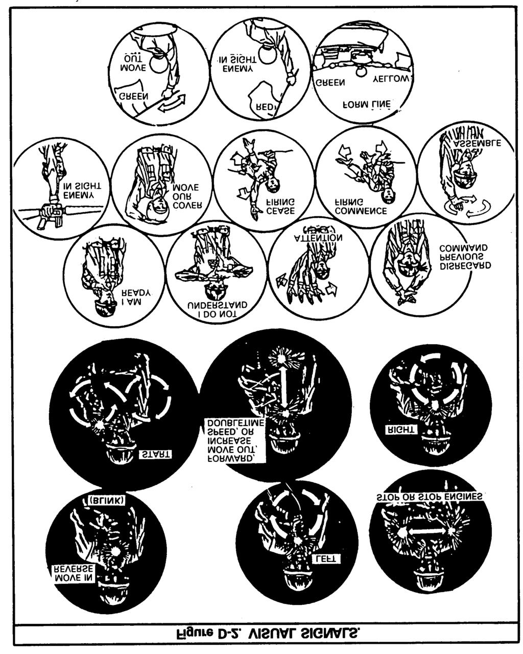
2 D-2. VISUAL Visual signals are the most common means of communicating in squads and platoons. Armand-hand signals, flags, flashlights, and pyrotechnics can be used to rapidly transmit messages and instructions. A disadvanage is that these signals may be seen by the enemy, but using the terrain properly lessens that chance. Another danger is that visual signals require visual contact between the sender and the receiver, and the signals may be misunderstood. To overcome this disadvantage, every man must be able to send, receive, and understand messages using visual signals. Squads and platoons must continually practice these signals. Arm-and-hand signals are the basic way of communicating within squads and platoons when visibility is good. Flag signals are easier to see and understand at greater distances than are arm-and-hand signals. Each APC and each tank has a set of three flags red, green, and yellow. Flashlight signals are used mainly for communicating during darkness. For identification, each squad or platoon may use a differently colored filter. Pyrotechnics can be used as signals at any time. In daylight, and in conditions of limited visibility such as fog, rain, or falling snow, they are less effective. Pyrotechnic signals are usually prescribed in the communications-electronics operating instructions. Squads and platoons are not to improvise and use their own pyrotechnic signals. They may conflict with the CEOI and confuse other units Pyrotechnic messages must be confirmed as soon as possible because the originator cannot be sure that the signal was seen and understood. CAUTION PYROTECHNIC SIGNALS ARE EASY FOR THE ENEMY TO INTERCEPT AND IMITATE. Mirrors, headlights, and panels are other means of visual communication but are difficult to use on the move. A complete list of each type of visual signal is in FM D-2
3 D-3
4 D-3. SOUND Sound communications include such simple devices as whistles, horns, gongs, and explosives. Sound signals are used mainly to attract attention, transmit prearranged messages, and spread alarms. Sound signals work but only for short distances. Battle noises cut down the range and reliability of sound signals. They are also open to enemy interception, so their use may be restricted for security. To avoid any misunderstanding, sound signals must be simple. They are usually prescribed by the unit SOP and the CEOI. D-4. MESSENGER Messengers are fairly secure means of communicating and usually the best way to send long messages that cannot be delivered personally by a commander. Using a messenger, though, is the slowest means of sending information, and it depends on the messenger not being delayed, captured, or killed. Message sent by messenger should be clear, concise, and complete. No unnecessary words should be used. If there is a chance the messenger might be captured, the message should be in code using the operational code in the CEOI. D-5. WIRE Wire communications should be used whenever tip platoon expects to stay in one place more than an hour. When possible, the whole platoon is tied together through the use of a wire net. The wire net consists of field wire laid among carrier teams and dismount teams. All field communications wire (WD-1 and combat assault) consists of two independently insulated strands twisted together to form one wire. There are several ways the platoon wire net can be set up, depending on whether the platoon is totally mounted or partially dismounted. In the mounted mode, the wire is laid from vehicle to vehicle and connected to the terminals on the right rear of each vehicle. Because TA-1 telephones (which are sound powered) are being used, one strand of the wire must be cut, the insulation stripped away and the wire ends attached to the wire terminal connectors on the right rear of the APC. The TA-1 is connected to the terminals on the inside of the vehicle by using a short length of wire. D-4
5 In the dismounted mode, situations are of two types. (1) In the first type, the platoon occupies one position with both the carrier element and the dismount element deployed. The wire net would be made by connecting all the platoon carrier teams and dismount teams together by wire. cause one strand of wire must be cut, the wire net is in series, which means that if the wire is bro- ken or disconnected the whole wire net will cease to function. Because the dismount teams use TA-1 s (as in the mounted mode), one strand of the wire must be cut, the insulation stripped back, and the wires attached to the binding posts of the TA-1 to connect the dismount teams to the wire net. Be- The carrier teams are connected to the wire net by stripping the insulation from the end of the strands of wire and inserting the wire ends into the binding posts of the AM/1780 audio fre- quency amplifier. The AM/1780 must be turned on while in the wire net. If it is turned off the wire net will not work. D-5
6 The T-splice method would be used for vehicles that connect to the wire net between the ends of the wire net. If the wire net starts at an APC, the wire would be connected to the binding posts of the AM/1780. This wire would be T-spliced into the wire net by cutting one strand of the wire, stripping back the insulation from the ends, and splicing the ends to the wire from the AM/1780. D-6
7 NOTE: A communications check must be made to insure that the wire net works. The C-2296 control box must be set in the ALL position. The AM/1780 is set for normal operations. If a carrier team cannot communicate with the rest of the teams, the strands of wire in the AM/1760 binding posts must be reversed and another check made. In the second type of dismounted situation, the dismount element is in a position different from that of the carrier element. In this placement, the dismount teams would use their TA-1 telephones to establish a platoon hot loop among themselves. When using the TA-1, one of the wires must be cut and the insulation stripped back to connect the wire to the telephone binding posts. The telephones do not have to be on the same single wire. Only one wire needs to be cut to connect the telephone. The wire net is laid from team to team until all teams are connected to it. Wire can also be laid between the carrier team and the dismount team of the same squad. To do this, the telephone must be with the dismount team. If a second telephone is not available, the wires must be connected directly into the APC s AM/1780. After the wire has been laid to all the carrier teams, it should be either buried several inches deep or strung overhead. This prevents vehicles damaging the wire or soldiers tripping over it. Before a vehicle moves more than a few feet, the track commander should insure that the telephone wire is disconnected. When a position is vacated, the wire should be recovered. D-6. RADIO Because Threat forces have an extensive radio intercept capability, radio is used within the platoon only when messages cannot adequately be sent by other means. If a radio transmission is intercepted, the enemy can usually find out where a unit is and what it is doing. When radios are used, transmissions must be short and to the point. The sender must know what he wants to say before he transmits. This helps to keep messages short and the radio net open for others to use. Also, it reduces vulnerability to enemy intercept. Each APC has an AN/GRC-160 radio mounted. The AN/GRC-160 can be configured as an AN/PRC-77. Additionally, the platoon leader s vehicle has either another AN/GRC-160 or an AN/VRC-46 mounted, and the platoon sergeant s vehicle may have an AN/VRC-64. Each squad, the platoon leader, and the platoon sergeant has either the squad radio AN/PRC-88 (transmitter AN/PRT-4 and receiver AN/PRR-9) or the smallunit transceiver (SUT) AN/PRC-68 for dismounted operations. There are five SUTs or AN/PRC-88 s per platoon. D
8 AN/VRC-46. The AN/VRC-46 radio is powered by the vehicle s electrical system. Its principal advantage is in its 41-kilometer planning range. If it or any other vehicular radio is operated when the vehicle engine is shut off, the driver must take care that the radio does not drain the batteries. AN/GRC-160. The AN/GRC-160 radio can be mounted in and operated from the vehicle, or it can be dismounted and used as a portable radio (AN/PRC-77). When mounted, it is powered by the vehicle s electrical system. The planning range mounted is 12 kilometers. When it is dismounted, it is called an AN/PRC-77 and can transmit up to 8 kilometers. It is powered by its own battery (BA-4836). AN/VRC-64. The AN/VRC-64 is similar to the AN/GRC-160 except that it does not come issued with the equipment necessary to make it man-portable. D-8
9 AN/PRC-88. Some units may be equipped with the AN/PRC-88 squad radio. The squad radio consists of two pieces of equipment, an AN/PRT-4 transmitter and an AN/PRR-9 receiver. Both the transmitter and receiver have preset crystal-controlled frequencies that can be changed as needed by the battalion communications platoon. AN/PRT-4. The transmitter of the squad radio is battery-powered and has two channels. Channel 1 has a range of 1,600 meters. Channel 2 has a range of 500 meters. The purpose of the about 28 hours. two channels is to give the platoon an alternate frequency. In addition to voice, the AN/PRT-4 can transmit atone. This may be used to send a prearranged signal, such as an alert from an observation post. Battery life is about 35 hours for the BA-399. AN/PRR-9. The receiver of the squad radio-will receive Channel 1 and Channel 2, one at a time. It is battery-powered. Two types of batteries can be used in the receiver. The dry cell battery (BA-505U) has a life of about 14 hours, and the magnesium battery (BA4505U) has a life of When the platoon leader is mounted, he communicates with the company commander using a vehicular radio (AN/VRC-46). He uses the second radio (AN/GRC-160) on the platoon frequency to communicate with the carrier teams and the dismount teams. When the platoon leader is dismounted, he uses the vehicular radio (AN/GRC-160) in the portable (AN/PRC-77) configuration to communicate with the company commander. He uses the AN/PRC- 68 or AN/PRC-88 on the platoon frequency to talk with the dismount teams and the carrier teams. Squad carrier teams use the vehicular radio (AN/GRC-160). The dismount team uses the AN/ PRC-68, or the AN/PRC-88. When the platoon leader stays mounted and the platoon sergeant dismounts, the platoon sergeant will use his AN/ PRC-68 or AN/PRC-88 to communicate with the dismount teams and the platoon leader. He may dismount the AN/GRC-160 as an AN/PRC-77 to monitor the company command net. D-7. INTERCOM SYSTEM The intercom system in each APC consists of three control boxes and three combat vehicle crew (CVC) helmets. The squad leader, TL/gunner, and driver use the CVC microphones and earphones to communicate over the vehicle intercom and radios. The rest of the men in each vehicle monitor D-9
10 the radio loudspeaker to stay abreast of the squad s situation. The AM/1780 amplifier should be kept in the commander-only (CDR ONLY) mode and the con- trol boxes (other than them) in the intercom- only (INT ONLY) mode. This will prevent unauthorized and accidental radio transmissions. This will also prevent accidental hot mikes which jam radio nets. During mounted movement, the crew wear the CVC helmet in place of the soldier s helmet. Before a crew member dismounts, he hangs his CVC helmet on a hook by his intercom system control box. This is done to prevent soldiers tripping over a CVC cord or headset cord or damaging the equipment. Section II. RADIOTELEPHONE PROCEDURES D-8. GENERAL Certain commonly used procedural words (prowords) have distinct meanings. They shorten the amount of time used in voice communication and avoid confusion. They are used when talking on the telephone or the radio. The most frequently used prowords include: OVER This is the end of my transmission to you and a response is necessary. Go ahead, transmit. SAY AGAIN Say again all of your last transmission. CORRECTION An error has been made in this transmission (or message indicated). The correct version is... I SAY AGAIN I am repeating transmission, or portion indicated. ROGER I have received your last transmission satisfactorily. WILCO I have received your message, understand it, and will comply. OUT This is the end of my transmission to you and no answer is required or expected. D-9. RULES FOR RADIO AND WIRE COMMUNICATIONS The following are rules for radio and wire communications: Listen before transmitting (sending). Make message short and clear. Speak clearly, slowly, in natural phrases; pronounce each word distinctly. If the receiving operator must write, allow him enough time for writing. If jammed (using radio), use the methods listed in the discussion on communication security (below). In all cases of radio and wire traffic, personnel should not waste time. Send the message and get off the net. D-10. COMMUNICATION SECURITY Communication security (COMSEC) denies or delays unauthorized persons from gaining valuable telecommunications information. It includes: Using correct authentication procedures to insure that the other communicating station is a friendly one. D-10
11 Using only approved codes. Restricting the use of radio transmitters, and monitoring radio receivers (radio listening silence). Enforcing net discipline and proper radiotelephone procedures. All stations operating in a net must use authorized call signs and prowords, and they must limit transmissions to official traffic. Selecting radio sites with a hill or other terrain feature between the sites and the enemy. Using directional antennas when it can be done, as discussed in appendix M, FM Using low power initially. Electronic counter-countermeasures (ECCM) prevent or overcome enemy electronic warfare. ECCM taken by a platoon mainly involve using proper signal security and antijamming techniques. Radio operators must use antijamming procedures to reduce enemy jamming effects. These procedures include: Recognition. When an operator s radio indicates interference, he first tries to find what is causing the interference. He should not immediately assume jamming, because jamming signs often are like other types of interference. Removal of the receiver antenna can help to find out if the interference is being produced internally by the receiver. If interference lessens when the antenna is removed, the problem is jamming. Continued operations. Normal radio operations should be continued, once jamming has been identified, so that the enemy cannot determine the jamming effects. The rule is: during jamming, continue operating unless ordered to shut down or shift to an alternate frequency. Do not say I AM BEING JAMMED over the radio. Reporting. All operators must report jamming to their next higher headquarters by some other means of communications for example, wire or messenger. The meaconing, intrusion, jamming, and interference (MIJI) report contains: Date and time of jamming. Frequencies affected. Type and strength of jamming signal. Designation of the unit making the report. D-11
LA6NCA LA6NCA
 Panzer IV communication system. From US INTELLIGENCE BULLETIN December 1942 A captured German training pamphlet contains the following information regarding the duties of the crew of a Mark IV tank, and
Appendix Suggested SOP for SINCGARS SOP
 1. References: Appendix Suggested SOP for SINCGARS a. TM 11-5820-890-10-1. b. TM 11-5820-890-20-1. c. FM 11-32. SOP 2. Purpose: This suggested SOP establishes procedures and guidelines for operating the
3 Planning the Jamming Operation
 CHAPTER 3 Planning the Jamming Operation An artillery commander s fire control element performs many geometric calculations prior to executing a fire mission. These calculations are necessary to bring
Portable Radio Fundamentals How to a use a portable, hand-held radio effectively in an emergency
 Portable Radio Fundamentals How to a use a portable, hand-held radio effectively in an emergency 6/30/04 (C) Virginia RACES, Inc. 2002, All Rights Reserved 1 Objectives: After completing this unit, you
Chapter 2 Threat FM 20-3
 Chapter 2 Threat The enemy uses a variety of sensors to detect and identify US soldiers, equipment, and supporting installations. These sensors use visual, ultraviolet (W), infared (IR), radar, acoustic,
TM OPERATOR S MANUAL
 OPERATOR S MANUAL Approved for public release; distribution is unlimited. SINCGARS GROUND COMBAT NET RADIO, NON-ICOM MANPACK RADIO AN/PRC-119 (NSN 5820-01-151-9915) (EIC: L2A) SHORT RANGE VEHICULAR RADIO
VISUAL SIGNALS TC MARCH Headquarters, Department of the Army
 TC 3-21.60 VISUAL SIGNALS MARCH 2017 DISTRIBUTION RESTRICTION: Approved for public release; distribution is unlimited. *This publication supersedes FM 21-60, 30 September 1987. Headquarters, Department
Chapter 4 FH Networks
 Chapter 4 FH Networks 4-1. FH Variables a. SINCGARS hops or changes frequencies about 100 times per second. The radio uses digital processing to control the hopping sequence and the pattern so that the
CHAPTER 19 SIGNALING TECHNIQUES
 CHAPTER 19 SIGNALING TECHNIQUES One of your first concerns when you find yourself in a survival situation is to communicate with your friends or allies. Generally, communication is the giving and receiving
Chapter 4. Meaconing, Intrusion, Jamming, and Interference Reporting
 Chapter 4 FM 24-33 Meaconing, Intrusion, Jamming, and Interference Reporting 4-1. Introduction a. Meaconing, intrusion, and jamming are deliberate actions intended to deny an enemy the effective use of
IMO. Resolution A.954(23) Adopted on 5 December 2003 (Agenda item 17) PROPER USE OF VHF CHANNELS AT SEA
 Adopted on 5 December 2003 (Agenda item 17) PROPER USE OF VHF CHANNELS AT SEA") INTERNATIONAL MARITIME ORGANIZATION E IMO ASSEMBLY 23rd session Agenda item 17 A 23/Res.954 26 February 2004 Original: ENGLISH Resolution A.954(23) Adopted on 5 December 2003 (Agenda item 17) PROPER USE
INTERNATIONAL MARITIME ORGANIZATION E IMO ASSEMBLY 23rd session Agenda item 17 A 23/Res.954 26 February 2004 Original: ENGLISH Resolution A.954(23) Adopted on 5 December 2003 (Agenda item 17) PROPER USE
TECHNICAL MANUAL DIRECT AND GENERAL SUPPORT MAINTENANCE MANUAL FOR AUDIO FREQUENCY AMPLIFIER AM-1780B/VRC (NSN ) (EIC: N/A)
 (EIC: N/A)") TECHNICAL MANUAL DIRECT AND GENERAL SUPPORT MAINTENANCE MANUAL FOR AUDIO FREQUENCY AMPLIFIER AM-1780B/VRC (NSN 5895-01-284-3057) (EIC: N/A) Distribution authorized to US Government agencies and their contractors
TECHNICAL MANUAL DIRECT AND GENERAL SUPPORT MAINTENANCE MANUAL FOR AUDIO FREQUENCY AMPLIFIER AM-1780B/VRC (NSN 5895-01-284-3057) (EIC: N/A) Distribution authorized to US Government agencies and their contractors
OTTO NoizeBarrierTM TAC
 OTTO NoizeBarrierTM TAC Advanced Communications Headset for Today s Modern Warfighter Proud United States Manufacturing Company Since 1961 OTTO NoizeBarrier TAC OTTO NoizeBarrier TM TAC Communications
Headset Intercom System. Operating Instructions
 Headset Intercom System Model C1025 Operating Instructions Headset and Transceiver Pack Base Station Model C1025 Table of Contents Intended Use...iii FCC Information...iii Service...iii System Descriptions...1
CHAPTER 11 RADIO OPERATING PROCEDURES CHAPTER
 SECTION 2 ESTABLISHMENT, MAINTENANCE AND OPERATION OF COMMUNICATION SYSTEMS AND EQUIPMENT CHAPTER 11 RADIO OPERATING PROCEDURES CHAPTER 11 INTRODUCTION 11.1 11.1 Whilst the standard radio operating procedure
Communications Technology Lab 6: Fibre-Optics Communications
 Communications Technology Lab 6: Fibre-Optics Communications Your report for this lab is to be a description of what was done. An optical fibre is a strand of glass or plastic with special optical properties
UNITED STATES MARINE CORPS FIELD MEDICAL TRAINING BATTALION Camp Lejeune, NC
 UNITED STATES MARINE CORPS FIELD MEDICAL TRAINING BATTALION Camp Lejeune, NC 28542-0042 FMSO 108 Communicate with a VHF Radio TERMINAL LEARNING OBJECTIVE. 1. Given a SL-3 complete VHF radio with a fill,
Walkie-Talkie. User Manual and Instruction. Getting Started
 Walkie-Talkie User Manual and Instruction Getting Started Installing the AA Batteries Your radio uses 3 AA Alkaline batteries. 1. With the back of the radio facing you, lift the battery latch up to release
USER MANUAL Universal Gateway U9921-GUV (P/N: 40994G-01)
") USER MANUAL Universal Gateway U9921-GUV (P/N: 40994G-01) 2012 DAVID CLARK COMPANY INCORPORATED Cautions and Warnings READ AND SAVE THESE INSTRUCTIONS. Follow the instructions in this installation manual.
USER MANUAL Universal Gateway U9921-GUV (P/N: 40994G-01) 2012 DAVID CLARK COMPANY INCORPORATED Cautions and Warnings READ AND SAVE THESE INSTRUCTIONS. Follow the instructions in this installation manual.
COMMUNICATIONS, AUTOMATION, AND POSITION/NAVIGATION SYSTEMS
 APPENDIX E COMMUNICATIONS, AUTOMATION, AND POSITION/NAVIGATION SYSTEMS E-1. Operational Facility Rules and Equipment a. The ability to communicate is esto C2 and the accomplishment of the sential assigned
COMMUNICATIONS, AUTOMATION, AND POSITION/NAVIGATION SYSTEMS
 APPENDIX E COMMUNICATIONS, AUTOMATION, AND POSITION/NAVIGATION SYSTEMS E-1. Operational Facility Rules and Equipment a. The ability to communicate is essential to C2 and the accomplishment of the assigned
CON NEX HP. OWNER'S MANUAL Full Channel AM/FM Amateur Mobile Transceiver TABLE OF CONTENTS TUNING THE ANTENNA FOR OPTIMUM S.W.R..
 TABLE OF CONTENTS PAGE SPECIFICATIONS... 2 INSTALLATION... 3 LOCATION... 3 CON NEX - 4300HP MOUNTING THE RADIO... 3 IGNITION NOISE INTERFERENCE... 4 ANTENNA... 4 TUNING THE ANTENNA FOR OPTIMUM S.W.R..
AM Radio Lab. How Stuff Works. Mission College. Brad #1 Brad #2 Brad #3 Brad #4. Introduction:
 How Stuff Works Hope College Mission College Name: AM Radio Lab Brad #1 Brad #2 Brad #3 Brad #4 Introduction: In this lab you will construct an AM radio receiver that operates without a battery. The energy
Operating Instructions
 FM Transmitter 2 Operating Instructions PLEASE READ ALL THE INSTRUCTIONS COMPLETELY BEFORE USE AND SAVE THIS MANUAL FOR FUTURE REFERENCE. Before Use Please read IMPORTANT SAFETY INSTRUCTIONS on pages 10-11
32 CHANNEL SELECTABLE CH MHZ DOWN VOLUME
 KARAOKE Professional UHF Wireless Microphone System VM-92U Operating Instructions UHF Frequency 64 Selectable Better Music Builder UHF MIC WIRELESS SYSTEM VM-92U 32 CHANNEL SELECTABLE 248 13.10 CH MHZ
STANDARD OPERATING PROCEDURES COMMUNICATIONS SYSTEM b RADIO DISCIPLINE AND TERMINOLOGY EFFECTIVE: JULY 2011
 STANDARD OPERATING PROCEDURES COMMUNICATIONS SYSTEM 204.2b RADIO DISCIPLINE AND TERMINOLOGY EFFECTIVE: JULY 2011 PURPOSE The purpose of this policy is to provide all members with general guidelines related
Reading and working through Learn Networking Basics before this document will help you with some of the concepts used in wireless networks.
 Networking Learn Wireless Basics Introduction This document covers the basics of how wireless technology works, and how it is used to create networks. Wireless technology is used in many types of communication.
3.1. Historical Overview. Citizens` Band Radio Cordless Telephones Improved Mobile Telephone Service (IMTS)
") III. Cellular Radio Historical Overview Introduction to the Advanced Mobile Phone System (AMPS) AMPS Control System Security and Privacy Cellular Telephone Specifications and Operation 3.1. Historical
III. Cellular Radio Historical Overview Introduction to the Advanced Mobile Phone System (AMPS) AMPS Control System Security and Privacy Cellular Telephone Specifications and Operation 3.1. Historical
Single Channel Radio Mic System USER MANUAL. WMU-116-H (Hand Held) WMU-116-B (Belt Pack) Single Channel Radio Mic System
 WMU-116-B (Belt Pack) Single Channel Radio Mic System") Single Channel Radio Mic System USER MANUAL WMU-116-H (Hand Held) WMU-116-B (Belt Pack) Single Channel Radio Mic System Welcome Thank you for choosing Hill Audio for your sound system. To make sure that
Single Channel Radio Mic System USER MANUAL WMU-116-H (Hand Held) WMU-116-B (Belt Pack) Single Channel Radio Mic System Welcome Thank you for choosing Hill Audio for your sound system. To make sure that
MAINTAINING OPTIMAL ALARM MONITORING COMMUNICATION
 MAINTAINING OPTIMAL ALARM MONITORING COMMUNICATION 2. MULTIUSER RF, DSSS AND PUBLIC NETWORKS Optimal communication from outstations to the control room is crucial to provide a reliable monitoring service.
Airborne Landings For WWII MicroArmour :The Game
 Airborne Landings For WWII MicroArmour :The Game by Leif Edmondson. The WWII rulebook presents some parachute landing rules in scenario #3 A Costly Setback and in the Modern MicroArmour rule book as well.
Chapter 5 SINCGARS Planning
 Chapter 5 SINCGARS Planning 5-1. Network Requirements a. The initial operations plan and unit SOP determine the type of net needed. The network planner must answer the following questions when planning
MobileRadio. Owner'sManual
 EMH MobileRadio Owner'sManual TABLE OF CONTENTS Introduction... 1 Basic Operation... 2 Code Guard Operation... 3 EMH Radio Controls... 4 Button Functions... 4 Built-in Features... 7 Keypad Microphone Operation...
TM-800 Main Station. Instruction Manual. TELIKOU Systems All Rights Reserved
 Intercom System TM-800 Main Station Instruction Manual TELIKOU Systems All Rights Reserved I. Introduction Thank you for choosing TELIKOU intercom product. TM-800 main station is suitable for television
WMD Wired microphone detector. Manufactured by SOLITON-TRON Ltd. HUNGARY
 WMD-2000 Wired microphone detector Manufactured by SOLITON-TRON Ltd. HUNGARY The WMD-2000 Acoustically Stimulated Microphone Detector is an electronic system for use by TSCM Inspectors for detecting audio
Technician Licensing Class. Antennas
 Technician Licensing Class Antennas Antennas A simple dipole mounted so the conductor is parallel to the Earth's surface is a horizontally polarized antenna. T9A3 Polarization is referenced to the Earth
SETUP and OPERATING MANUAL ADVANCED MULTI-CHANNEL VEHICLE INTERCOM SYSTEM (AMCVIS)
") SETUP and OPERATING MANUAL Sept 23, 2010 Rev D ADVANCED MULTI-CHANNEL VEHICLE INTERCOM SYSTEM (AMCVIS) with DIGITAL CREW CONTROL and RADIO BRIDGING The AMCVIS was designed, manufactured and is supported
SETUP and OPERATING MANUAL Sept 23, 2010 Rev D ADVANCED MULTI-CHANNEL VEHICLE INTERCOM SYSTEM (AMCVIS) with DIGITAL CREW CONTROL and RADIO BRIDGING The AMCVIS was designed, manufactured and is supported
TELIKOU Intercom System
 TELIKOU Intercom System DT-100 Desktop Station Instruction Manual 2006 TELIKOU Systems All Rights Reserved www.telikou.com While TELIKOU makes every attempt to maintain the accuracy of the information
Improving Performance through Superior Innovative Antenna Technologies
 Improving Performance through Superior Innovative Antenna Technologies INTRODUCTION: Cell phones have evolved into smart devices and it is these smart devices that have become such a dangerous weapon of
TACTICAL SINGLE-CHANNEL RADIO COMMUNICATIONS TECHNIQUES
 Field Manual No. 24-18 FM 24-18 HEADQUARTERS DEPARTMENT OF THE ARMY Washington, D.C. 30 September 1987 TACTICAL SINGLE-CHANNEL RADIO COMMUNICATIONS TECHNIQUES TABLE OF CONTENTS PREFACE iv CHAPTER 1 INTRODUCTION
TCI Library-
 Section L of TELEPHONE EQUIPMENT & SUPPLIES CATALOG ISSUED SEPTEMBER, 1966 RECORDERS & ANNOUNCERS Recorder,-Announcers Type INT, Single-Channel, Fixed Message Length, Compact Transistorized Recorder-Announcers;
800 System Procedures
 Emergency Button Activation: 800 System Procedures All ACFR radios are equipped with emergency button functionality. When this button is activated by the end-user, an audible alarm and a flashing visual
Heritage MedCall. Sentry E-Call Model HM-527 Resident Host Panel
 Heritage MedCall Sentry E-Call Model HM-527 Resident Host Panel 430-527B 0305 Heritage MedCall, Inc. Issue 1, March 2005 Heritage Medcall Sentry Emergency Call System Model 527 Host Panel Installation
Chapter 3 Antennas. Section I. Antenna Selection FM 24-19
 Chapter 3 Antennas One of the most important considerations when operating a radio is the type of antenna to be used. For good communications with a radio operating in the HF range (2.000 khz to 29.999
ARCHIVED REPORT. Jaguar/Caracal/Panther - Archived 6/2005
 C 4 I Forecast ARCHIVED REPORT For data and forecasts on current programs please visit www.forecastinternational.com or call +1 203.426.0800 Jaguar/Caracal/Panther - Archived 6/2005 Outlook Forecast International
BARROW COU TY BARROW COU TY EMERGE CY RADIO COMMU ICATIO PLA EMERGE CY SERVICES. This document for CERT Operations only.
 BARROW COU TY BARROW COU TY EMERGE CY SERVICES EMERGE CY RADIO COMMU ICATIO PLA The instructions contained in this handbook are intended for the use by Barrow County members only. Barrow County 233 E.
WPT-3000 Wireless Probe Transmitter. Owner s Manual
 WPT-3000 Wireless Probe Transmitter Owner s Manual Warnings This device complies with Part 15 of the FCC rules, operation of this device is subject to the following conditions: 1. This device may not cause
CMA-100. User Manual. Counter Measures Amplifier
 CMA-100 Counter Measures Amplifier User Manual Research Electronics International, LLC 455 Security Drive, Cookeville, TN 38506 U.S.A. (800) 824-3190 (US Only) +1 931-537-6032 www.reiusa.net Copyright
Team Radio Operations Standard Operating Procedures
 Team Radio Operations Standard Operating Procedures Pre-deployment check: 1. Make sure you are familiar with the radio and all of it's functions. If you need, carry the manual, or a manual "cheat sheet"
DELUXE 18CHANNEL SSB/AM CB TRANSCEIVER OWNER'S GUIDE
 DELUXE 18CHANNEL SSB/AM CB TRANSCEIVER OWNER'S GUIDE General Description The Bush Ranger is a combination transmitter and receiver designed for use in the Australian 27 MHz Citizens radio service. It is
Model: TP380 User Manual
 Model: TP380 User Manual 1 UHF RADIO TRANSCEIVER MODEL: TP380 USER MANUAL INTRODUCTION Thank you for selecting the Oregon Scientific TP380 as your product of choice. This product is a portable, easy-to-use
WS-29 DUAL CHANNEL WIRELESS BELTPACK
 WS-29 DUAL CHANNEL WIRELESS BELTPACK USER MANUAL Issue March 2011 ASL Intercom BV DESIGNED AND MANUFACTURED BY: ASL INTERCOM BV ZONNEBAAN 42 3542 EG UTRECHT THE NETHERLANDS PHONE: +31 (0)30 2411901 FAX:
Installation & User Guide. For Powering Distributed Audio Systems A45-X2 TWO CHANNEL AMPLIFIER
 Installation & User Guide For Powering Distributed Audio Systems TWO CHANNEL AMPLIFIER A45-X2 A45-X2 TWO CHANNEL AMPLIFIER TABLE OF CONTENTS Features...1 Product Overview...2 Package Contents...4 Preparing
KMA 24 and KMA 24H Bendix/King Audio Control Systems
 KMA 24 and KMA 24H Bendix/King Audio Systems Compact TSO d consoles make audio control push button simple Push button simplicity puts complete, flexible audio control right at your fingertips with Bendix/King
Users Manual. 200W HF/50MHz Band Auto Antenna Tuner. Model HC-200AT
 Users Manual 200W HF/50MHz Band Auto Antenna Tuner Model HC-200AT Caution 1. Never remove or open the tuner cover while transmitting. When there is RF in the circuits of the tuner, there will be high voltage
An analysis of Cannon By Keith Carter
 An analysis of Cannon By Keith Carter 1.0 Deploying for Battle Town Location The initial placement of the towns, the relative position to their own soldiers, enemy soldiers, and each other effects the
OPERATING INSTRUCTIONS. VHF Transceiver AR Subject to technical changes
 OPERATING INSTRUCTIONS VHF Transceiver AR 3209 BECKER FLUGFUNKWERK GMBH Baden Airpark D-77836 Rheinmünster (Germany) Tel.: +49 (0) 7229 / 305-0 Fax: +49 (0) 7229 / 305-217 Subject to technical changes
SR-102 PRODUCT SUPPORT MANUAL. Y Rev. B. GMDSS 16/6 Survival Radio. Product No. 2726A
 PRODUCT SUPPORT MANUAL Y1-03-0079-1 Rev. B SR-102 Product No. 2726A GMDSS 16/6 Survival Radio ACR Electronics, Inc. 5757 Ravenswood Road Fort Lauderdale, Fl 33312 +1(954) 981-3333 Fax +1 (954) 983-5087
VOLUSIA ARES DEPLOYMENT MANUAL
 VOLUSIA COUNTY AMATEUR RADIO EMERGENCY SERVICE VOLUSIA ARES DEPLOYMENT MANUAL Effective Date: December 1, 2010 Stephen G. Craft, W1SGC Volusia County Emergency Coordinator DEPLOYMENT MANUAL Hospital and
RU210. Dual Multi-UHF Wireless System. Item ref: UK, UK User Manual. Version 1.0
 RU210 Dual Multi-UHF Wireless System Item ref: 171.970UK, 171.971UK User Manual Version 1.0 Caution: Please read this manual carefully before operating Damage caused by misuse is not covered by the warranty
INDEX PREFACE... 1 CAUTIONS... 2 OPERATION ON SITE(9) STANDARD INSTRUMENT... 3 OPTIONAL ACCESSORIES... 4 OPERATION OF TRANSMITTER(3)...
 STANDARD INSTRUMENT... 3 OPTIONAL ACCESSORIES... 4 OPERATION OF TRANSMITTER(3)...") INDEX PREFACE... 1 CAUTIONS... 2 STANDARD INSTRUMENT... 3 OPTIONAL ACCESSORIES... 4 OPERATION OF TRANSMITTER(1)... 5 (Transmitter Unit.) OPERATION OF TRANSMITTER(2)... 6 (Operation Panel, LCD Display of
INDEX PREFACE... 1 CAUTIONS... 2 STANDARD INSTRUMENT... 3 OPTIONAL ACCESSORIES... 4 OPERATION OF TRANSMITTER(1)... 5 (Transmitter Unit.) OPERATION OF TRANSMITTER(2)... 6 (Operation Panel, LCD Display of
Installation & Operation Manual SAGA1-K Series Industrial Radio Remote Control
 Installation & Operation Manual SAGA1-K Series Industrial Radio Remote Control Gain Electronic Co. Ltd. Table Of Contents Safety Considerations ------------------------------------------------------------2
Important safety instructions
 MMR-88 Version 1 Important safety instructions 1. 2. 3. 4. 5. 6. 7. 8. 9. Please read these instructions carefully. Please keep these instructions for future reference. Heed all warnings Follow all instructions
2.1 FCC Federal Communications Commission Wireless Telecommunication Bureau.
 Effective Date: 11/29/2017 Legal Review Date: N/A Next Review Date: 07/31/2020 Replaces: 6/15/2016 Approved: 11-28-2017 1.0 Purpose and Scope: WESTERN PACIFIC RAILROAD MUSEUM POLICY Radio Policy and Protocol
M508 GPS Tracking Device
 M508 GPS Tracking Device (GPS+GPRS+GSM) Product Manual Edition 1.3 Copyright 10 th Oct., 2009 GATOR GROUP CO.,LTD. All rights reserved. http://www.gatorcn.com China Printing ADD: 312# Ansheng Building,Xixiang
DCPT-2500 Wireless Probe Transmitter. Owner s Manual
 DCPT-2500 Wireless Probe Transmitter Owner s Manual DCPT-2500 Manual.indd 1 5/5/2010 3:04:05 PM Warnings This device complies with Part 15 of the FCC rules, operation of this device is subject to the following
SP980. Cordless Stereo 863MHZ. Speaker System. User s Manual INTRODUCTION FEATURES. Please read before using the equipment
 SP980 Cordless Stereo 863MHZ Speaker System INTRODUCTION This 863 MHz stereo wireless speaker system uses latest wireless technology that enables you to enjoy music and TV sound anywhere inside or outside
2. Electronics use analogue and digital systems, the basic circuit elements of which are potential dividers and transistors
 2. Electronics use analogue and digital systems, the basic circuit elements of which are potential dividers and transistors 2.1 Describe the difference between an electronic circuit and an electric circuit
REDSUN PF2100 PLL RADIO OPERATING MANUAL
 REDSUN PF2100 PLL RADIO OPERATING MANUAL TRANSLATED BY LIYPN ALL RIGHTS RESERVED JUNE 2006 (We are the copyright holder of this manual in English. Please do NOT distribute this manual in any form nor post
DA216S DISTRIBUTION AMPLIFIER
 DISTRIBUTION AMPLIFIER IMPORTANT SAFETY INSTRUCTIONS 1. Read these instructions. 2. Keep these instructions. 3. Heed all warnings. 4. Follow all instructions. 5. Do not use this apparatus near water. 6.
RMV25 / RMV50 RMU25 / RMU45
 RMV25 / RMV50 RMU25 / RMU45 Owner's Manual TABLE OF CONTENTS INTRODUCTION... 3 FCC Requirements... 3 SAFETY WARNING INFORMATION... 3 CONTROLS and INDICATORS... 5 FRONT PANEL... 5 LCD Icons and Indicators...
Non-Ham Radio Communications Systems By Glen Sage, W4GHS
 Non-Ham Radio Communications Systems By Glen Sage, W4GHS Amateur Radio (Ham Radio) provides outstanding systems with various modes to provide communications back to the Baptist Mission Boards both state
SAFETY INFORMATION IMPORTANT FCC LICENSING INFORMATION
 This device complies with part 15 of the FCC Rules. Operation is subject to the following two conditions: (1) This device does not cause harmful interference, and (2) This device must accept any interference
MAINTAINING OPTIMAL ALARM MONITORING COMMUNICATION
 MAINTAINING OPTIMAL ALARM MONITORING COMMUNICATION 1. VHF RADIO FREQUENCY PRIVATELY OWNED NETWORKS Optimal communication from outstations to the control room is crucial to provide a reliable monitoring
Personal Role Radio. All-informed communications
 Personal Role Radio All-informed communications The SELEX Communications Personal Role Radio (PRR) can significantly enhance team effectiveness by providing all-informed communications for manned guarding,
How Radio Works by Marshall Brain
 How Radio Works by Marshall Brain "Radio waves" transmit music, conversations, pictures and data invisibly through the air, often over millions of miles -- it happens every day in thousands of different
Setup and Operating Procedures ICRI-9575P Incident Commanders Radio Interface
 COMMUNICATIONS-APPLIED TECHNOLOGY 11250-14 Roger Bacon Drive Reston, VA 20190 U.S.A. Voice: +1-703-481-0068 Support: Techsupport@c-at.com Setup and Operating Procedures ICRI-9575P Incident Commanders Radio
AT RF20 MultiBand Handheld Transceiver
 AT RF20 MultiBand Handheld Transceiver AT RF20 MultiBand Handheld Transceiver AT RF20 ECCM handheld multiband transceiver with improved resistance to electronic warfare is designated for use at the lowest
WTI-100 Simplex wireless Interface Instruction Manual
 TELIKOU Intercom System WTI-100 Simplex wireless Interface Instruction Manual 2006 TELIKOU Systems All Rights Reserved www.telikou.com While TELIKOU makes every attempt to maintain the accuracy of the
Use of UHF Radios in the Field Procedure. Issue Date: 02/05/2012 Review Date: 02/05/2014
 Use of UHF Radios in the Field Procedure Issue Date: 02/05/2012 Review Date: 02/05/2014 PROCEDURE: REV: 0 STATUS: ISSUED FOR USE DOC OWNER: HSE SYSTEMS MANAGER Purpose This Procedure details the safe use
AZATOM SONANCE T1 Digital Radio. DAB+/DAB/FM Radio Alarm Clock. User Manual. This manual is available to download online at
 AZATOM SONANCE T1 Digital Radio DAB+/DAB/FM Radio Alarm Clock User Manual This manual is available to download online at www.azatom.com Thank you for shopping with AZATOM Please read this manual carefully
WIRELESS FIRST RESPONDER OPERATING MANUAL
 WIRELESS FIRST RESPONDER OPERATING MANUAL Version: 03.16 TABLE OF CONTENTS: TOPIC PAGE #(s) Standard Components & Accessories 1 Loudspeaker, VHF Wireless Transmitter Pack & Microphone Specifications 2
IFH SS CDMA Implantation. 6.0 Introduction
 6.0 Introduction Wireless personal communication systems enable geographically dispersed users to exchange information using a portable terminal, such as a handheld transceiver. Often, the system engineer
Technician Licensing Class. Lesson 4. presented by the Arlington Radio Public Service Club Arlington County, Virginia
 Technician Licensing Class Lesson 4 presented by the Arlington Radio Public Service Club Arlington County, Virginia 1 Quiz Sub elements T6 & T7 2 Good Engineering Practice Sub element T8 3 A Basic Station
Technician License Course Chapter 2. Lesson Plan Module 3 Modulation and Bandwidth
 Technician License Course Chapter 2 Lesson Plan Module 3 Modulation and Bandwidth The Basic Radio Station What Happens During Radio Communication? Transmitting (sending a signal): Information (voice, data,
GM1200 User Guide. GM1200 User Guide. English. Contents
 GM1200 User Guide GM1200 User Guide Contents Page: General Information... 2 Radio Controls... 2 Display Icons... 3 Audio Tones... 3 Turning the Radio On/Off... 4 Making a Call... 5 Shortform Dialling...
2018 HSS Development
 Communications Intelligence - Mobile Collection - Situational Awareness - Tracking Identities Electronic Warfare - RF Jamming - Programmable Applications Prison Solutions - Managed Access - Denial of Service
ALWAYS ATTACH THE SAFETY ROPE TO A STABLE SUPPORT BEFORE ATTEMPTING TO ATTACH THE UNIVERSAL MOUNT TO A WINDOW FRAME OR RAIL.
 MFJ-1623 Introduction The MFJ-1623 was designed to provide portable or permanent HF communications on 30 through 10 meters and VHF on 6 meters. The universal mount design allows the user to install the
INSTRUCTION MANUAL VHF FM TRANSCEIVER TK-7102H UHF FM TRANSCEIVER TK-8102H KENWOOD CORPORATION B (M)
") INSTRUCTION MANUAL VHF FM TRANSCEIVER TK-7102H UHF FM TRANSCEIVER TK-8102H KENWOOD CORPORATION B62-1596-00 (M) 09 08 07 06 05 04 03 02 01 00 THANK YOU! We are grateful you chose KENWOOD for your personal
INSTRUCTION MANUAL VHF FM TRANSCEIVER TK-7102H UHF FM TRANSCEIVER TK-8102H KENWOOD CORPORATION B62-1596-00 (M) 09 08 07 06 05 04 03 02 01 00 THANK YOU! We are grateful you chose KENWOOD for your personal
WORLD BAND RADIO. AM/FM/SW/L W/AIR Band /SSB radio with LCD backlight OWNER S MANUAL
 WORLD BAND RADIO AM/FM/SW/L W/AIR Band /SSB radio with LCD backlight display and keypad direct entry OWNER S MANUAL WARNING Do not expose this appliance to rain or moisture Do not submerge or expose to
WARNING. Basic Features of the Amplifier system. Meeting
 PWMA100 PWMA200 We thank you for your purchasing this amplifier system.before you use your new amplifier system, please read the manual book thoroughly and carefully. Please keep this instruction book
TELEPHONE BUG KIT MODEL K-35. Assembly and Instruction Manual
 TELEPHONE BUG KIT MODEL K-35 Assembly and Instruction Manual Elenco Electronics, Inc. Copyright 2010, 1989 by Elenco Electronics, Inc. All rights reserved. Revised 2010 REV-L 753235 No part of this book
SUBELEMENT T4. Amateur radio practices and station set up. 2 Exam Questions - 2 Groups
 SUBELEMENT T4 Amateur radio practices and station set up 2 Exam Questions - 2 Groups 1 T4A Station setup: connecting microphones; reducing unwanted emissions; power source; connecting a computer; RF grounding;
VisorTrac A Tracking System for Mining
 VisorTrac A Tracking System for Mining Marco North America, Inc. SYSTEM APPLICATION The VISORTRAC system was developed to allow tracking of mining personnel as well as mining vehicles. The VISORTRAC system
Pair of PMR446 Two-Way Personal Radios Model: TP391
 Pair of PMR446 Two-Way Personal Radios Model: TP391 USER MANUAL MANUALE D USO MANUEL DE L UTILISATEUR BEDIENUNGSANLEITUNG MANUAL DE USUARIO MANUAL DO USUÁRIO HANDLEIDING BRUKSANVISNING P/N:086L004722-016
Owner s Manual. Model FR-1400 Two Way Family Radio A 1 of 20. Customer Service Manufacturer will reduce to 75 per cent.
 Owner s Manual Model FR-1400 Two Way Family Radio Customer Service 1-800-290-6650 Released on 8-18-00. Revision A: Changed pages 13 and 16, 11-3-00. 1 of 20 Manufacturer will reduce to 75 per cent. CONGRATULATIONS
Tactical Radio Products. U.S. Government Products. The most comprehensive. family of tactical radios, available today. FALCON II
 Tactical Radio Products U.S. Government Products The most comprehensive family of tactical radios, available today. FALCON II Outperforming the Competition. The FALCON II software-defined radios provide
On-Line Cardio Theater Wireless Digital Transmitter Installation and Instruction Manual
 On-Line Cardio Theater Wireless Digital Transmitter Installation and Instruction Manual Full installation instructions accompany your Cardio Theater equipment order. This On-Line version of our Installation/Instruction
ic-f1020 ic-f2020 INSTRUCTION MANUAL VHF LAND MOBILE RADIO UHF LAND MOBILE RADIO
 INSTRUCTION MANUAL VHF LAND MOBILE RADIO ic-f1020 UHF LAND MOBILE RADIO ic-f2020 This device complies with Part 15 of the FCC Rules. Operation is subject to the condition that this device does not cause
The Aces High Radio. by Hammer
 by Hammer There are 5 "radios" available to you in Aces High. These radios allow you to communicate with members of your country, members of your squad, friendlies who are nearby, members of other countries,