Optical Theremin Critical Design Review Yanzhe Zhao, Mason Story, Nicholas Czesak March
|
|
|
- Melina Skinner
- 6 years ago
- Views:
Transcription
1 Optical Theremin Critical Design Review Yanzhe Zhao, Mason Story, Nicholas Czesak March
2 Abstract A theremin is a musical instrument whose tone and pitch can be controlled without physical contact. A traditional theremin makes use of antennas and oscillators in order to allow the user to control the volume and pitch. However, there are a number of ways to implement the overall design for a theremin without the use of antennas and oscillators. One of them takes the form of what is known as an optical theremin, which uses the intensity of incoming light rays to control the characteristics of the theremin. A useful method of implementing an optical theremin is the use of two OP906 photodiodes. Passing each current generated through two 1 MΩ feedback resistors implemented with two Texas instrument s TL074 lownoise JFET-input Op-Amps produces two output voltages that can be thought of as the volume and pitch, respectively, of the optical theremin. The magnitude of the output voltage is therefore controlled by the intensity of light shined of the photodiodes, which can be controlled through how the user moves their hand relative to the diodes themselves. This data can then be input into an NI mydaq and processed through an NI LabVIEW program. The LabVIEW program can normalize and scale the data to fit the requirements of the optical theremin, and afterwhich include settings for auto-tuning and distortion. The final waveform should be able to be output by the mydaq and processed by a set of speakers to produce an audio signal. Introduction In order to prototype a minimalistic, functional optical theremin our team will first have to decide how best to obtain a signal from the intensity of ambient lighting. With minimal parts provided we had to come up with a simple design with most of the manipulation occurring within LabVIEW. The final design our team constructed provides the user with complete manipulation of the audio signal through LabVIEW and the intensity of the ambient lighting. With a fully customizable front panel our solution provides further customization in the future. Our team designed a solution assuming that the user is in a well lit room with basic knowledge of LabVIEW. Our vision is to develop a fully customizable LabVIEW VI in conjunction with a simple integrated circuit design. This project will provide the ability to operate a optical theremin with complete signal manipulation capabilities including scalability, auto-tune ability, and distortion. The specific problems we encountered within our design were the normalization and scaling of the signal, auto-tuning of the frequency, and distortion of the amplitude. The signal voltage obtained through the MyDAQ will vary with the intensity of the ambient lighting of the room. In order to provide a consistent signal it first needs to be normalized between 0 and 1 volt. With normalization this allows the user to take the optical theremin into any room and quickly calibrate it; our design allows this to happen. With a normalized frequency and amplitude the user can then determine the limits of the frequency via controls on the front panel. Our solution provides the user the option to limit the theremin to a single octaves or a multitude of octaves. The ambient lighting in the room will provide noise within the signal, so in order to account for the frequencies our solution provides a auto-tuning function to coerce the raw pitch to a whole note pitch. Finally our solution allows the user to distort his signal in two distinct ways providing variety from the theremin. The theory behind our solution is provided within the rationale section and the specific setup is described within the implementation section of this paper.
3 Rationale In order to make a functional optical theremin with photodiodes we decided on using a transimpedance amplifier. With the photodiodes acting as current sources, the transimpedance amplifier will produce a gain voltage dependant on the feedback resistor and the current from the diodes. With the signal produced by the photodiodes in a voltage, the mydaq can transfer the signal into LabVIEW for manipulation. Once in LabVIEW the signal will first need to be normalized. This will make any signal manipulations easier because the signal is now between zero and one volt. Normalization was achieved by implementing a calibration scale on the front panel in LabVIEW. With the given requirements that the final audio signal be contained within 20Hz to 20KHz we needed to scale that the signal and offset it accordingly. We multiplied the normalized waveform with the difference of the maximum and minimum desired frequencies. This in conjuncture of the minimum frequency offset will produce a signal within the specified frequencies. The last requirement for the first portion of this project was to implement a normalized, scaled, volume. Similar to the frequency, the voltage for the amplitude was normalized by implementing a calibration control on the front panel in LabVIEW. The next portion of the project required a user controlled switch to select the frequency used to generate the audio waveform. The two options were the unmanipulated frequency generated from the scaled normalization waveform or a auto-tuned frequency. In order to auto-tune the frequency, our signal was compared to an array of scientifically established note frequency; we decided on eight octaves ranging from 20Hz to 20KHz. Our signal was then corrected to the scientific frequency by thresholding the value to the closest determined pitch. The final portion of our lab was to add distortion to our signal. There were three options to implement no clipping, hard clipping, and soft clipping. No clipping had no effect on the original waveform. Hard and soft clipping altered the peak voltage based on a control on the front panel in LabVIEW. Hard clipping coerced the signal to stay within the values decided by the control. This results in a straight cutoff with sharp edges on the waveform. Soft clipping required the signal generated to be divided by the percentage of clipping this provides the exponent we can apply to our signal. This allows us to distort our signal while maintaining our curved peak on the waveform. Implementation We used op906 photodiodes as a negative current source leading from the LT074CN operational amplifier with feedback resistors of 1 MΩ to implement two transimpedence amplifiers using two of the opamps on the integrated circuit; specifically pins 1 through 7 see Appendix A. We sampled both analog input channels on our mydaq to create two channels corresponding to frequency and amplitude for our optical theremin which we separated in LabVIEW more information can be found in Appendix B. To eliminate noise within the waveforms we averaged out the signals using LabVIEW s mean function. For frequency we calibrated the normalization, scaled the waveform, and implemented a frequency offset within a formula node as seen in figure A. The calibration controls to normalize the frequency are MaxInt and MinInt with range of 0 to 10. Once normalized between 0 and 1 Volt the controller can set the range that the frequency can vary using the MinFreq and MaxFreq controls with the limits being 20Hz and 20KHz. The difference in this range is multiplied by the normalization in order to scale the signal to the desired level so that when the MinFreq is added to the waveform the signal is meets the specifications. Another control is used to calibrate the normalization of the amplitude. This control is split into a Max and a Min used in the normalization equation with the signal values X.
4 We then implemented a SubVI in order to auto-tune the frequency. Within this VI we use LabVIEW s threshold function, where our scaled frequency is one input and an array of scientifically accepted note frequencies is the other input. When the user selects the auto-tune function, the raw frequency is compared with the note frequency array and the thresholding function returns a fractional index. We round the index down to the nearest whole number and extract the corresponding scientific pitch to replace in our waveform. With a new frequency and amplitude we use the simulate signal function to produce an audio signal within the specifications of the mydaq audio out limits of 土 2 volts see Appendix B. To simplify the distortion portion of this project we used a case structure with enumerated states of no clipping, hard clipping, and soft clipping. We also used a slider on the front panel with a scale of.3 to.9 or the range of clipping required. The no clipping state required no manipulation of the signal. Hard clipping uses the coerce function with the input of our signal and the limits of the positive and negative value obtained by the clipping slider control. The soft clipping required our clipping control divided by the waveform value to produce a exponent to linearly compress our original waveform without hard clipping. The entirety of the LabVIEW schematic can be found in Appendix F. Conclusion By the end of the first week of March, we were able to develop a final design for the overall circuit. This included the transimpedence amplifier circuit and the virtual circuit that was developed through LabVIEW. The schematic for the amplifier, its assembly, and measurements taken presented little problems to us. The real challenge from the project came with the realization of the LabVIEW code. However, in the end, our final design met the needs for the project and was able to communicate with the signal produced by the transimpedance amplifier circuit. We were able to generate an audio signal from the mydaq that could be processed and output by a set of speakers. We were able to normalize the data coming from the amplifier circuit by making use of the function node in our Block Diagram. This helped to condense our code to a smaller section of the Block Diagram than when we tried to implement arithmetic VI s. This method of implementation would also be significantly more readable for anyone analyzing our Block Diagram and trying to comprehend what the code was trying to accomplish. In regards to the auto-tuning of the theremin, the SubVI we utilized was successful with our method of programming it, which involved setting up an array containing all the specific frequencies contained within each octave. We realize now this may not have been the most efficient way to accomplish this task. This influenced our decision to generate a SubVI for this section of LabVIEW code so it wouldn t take up significant space in our Block Diagram. After passing through the AutoTune SubVI, the new data then passed through a simulate signal function producing the audio signal. This new audio signal section of code dealt with the clipping of the audio signal to produce distortion. The method to accomplish this, which involved the use of a case structure, was deemed pretty obvious by everyone on the team after reading through the requirements. The real challenge revealed itself when we were discussing how to implement each choice for clipping provided to the user. In the end, the final result seemed to mesh well with the remaining portions of the block diagram. Overall, the LabVIEW code utilized in this project proved to be more than enough to accomplish all of the required tasks. The only problem that was encountered in our overall design was the use of a diode to change the volume of the theremin. Covering the diode actually caused the volume to rise instead of
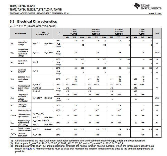
5 decrease. This is not what we were expecting to occur, although it had no effect on any of the other controls used in the final design, especially the other diode that was used to control frequency. Appendices Appendix A: Data Sheet for TL074 low-noise JFET-input Op-Amp:
6 :


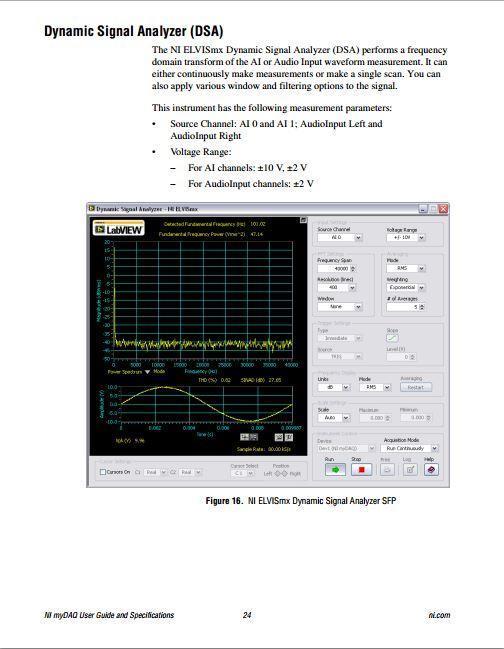
7 Appendix B: Data Sheet for NI mydaq:
8
9
10 Appendix C: OP906 Diode Datasheet:


11 Appendix D: Block Diagram for the Optical Theremin:

12 Appendix E: Gantt Chart Appendix F: LabVIEW code
13 Theremin Main VI: AutoTune SubVi: Pitch array containing 8 octaves of frequencies
EE 300W Lab 2: Optical Theremin Critical Design Review
 EE 300W Lab 2: Optical Theremin Critical Design Review Team Drunken Tinkers: S6G8 Levi Nicolai, Harvish Mehta, Justice Lee October 21, 2016 Abstract The objective of this lab is to create an Optical Theremin,
Lab 2: Optical Theremin Team 2 Flyback By Brian Pugh, Andrew Baker, and Michael Betts
 Lab 2: Optical Theremin Team 2 Flyback By Brian Pugh, Andrew Baker, and Michael Betts Table of Contents Abstract... 3 Introduction... 3 Rationale... 4 Implementation... 5 Hardware... 5 Software... 5 Conclusion...
Optical Theremin CDR
 William Cane Wissing James Jones Mackenzie Phelps EE 300w Sec 003 Abstract Optical Theremin CDR For this lab we created an optical theremin. A theremin is an electronic instrument controlled without any
EE 300W 001 Lab 2: Optical Theremin. Cole Fenton Matthew Toporcer Michael Wilson
 EE 300W 001 Lab 2: Optical Theremin Cole Fenton Matthew Toporcer Michael Wilson March 8 th, 2015 2 Abstract This document serves as a design review to document our process to design and build an optical
Lab 2: Designing an Optical Theremin. EE 300W Section 5 Team #3: Penn Power United Gregory Hodgkiss, Nasser Aljadeed 10/23/15
 Lab 2: Designing an Optical Theremin EE 300W Section 5 Team #3: Penn Power United Gregory Hodgkiss, Nasser Aljadeed 10/23/15 Abstract The purpose of this lab is to design an optical theremin, a musical
THE PENNSYLVANIA STATE UNIVERSITY. Lab 2: Designing Optical Theremin Instrument. EE 300W Section 001. Nathaniel Houtz, Ji Eun Shin, Peter Wu 2/22/2013
 THE PENNSYLVANIA STATE UNIVERSITY Lab 2: Designing Optical Theremin Instrument EE 300W Section 001 Nathaniel Houtz, Ji Eun Shin, Peter Wu 2/22/2013 1 ABSTRACT A simple Theremin must be able to produce
Optical Theremin Critical Design Review
 1 Optical Theremin Critical Design Review EE 300W Team Laplace: Richard Michael Sean Solley Ye Zhang 10/23/15 2 Abstract: Team Laplace successfully designed a working Optical Theremin with equalizing and
Infrared Communications Lab
 Infrared Communications Lab This lab assignment assumes that the student knows about: Ohm s Law oltage, Current and Resistance Operational Amplifiers (See Appendix I) The first part of the lab is to develop
Lab 9: Operational amplifiers II (version 1.5)
") Lab 9: Operational amplifiers II (version 1.5) WARNING: Use electrical test equipment with care! Always double-check connections before applying power. Look for short circuits, which can quickly destroy
Lab 9: Operational amplifiers II (version 1.5) WARNING: Use electrical test equipment with care! Always double-check connections before applying power. Look for short circuits, which can quickly destroy
Theremin with Onboard Effects by Patrick Tarantino Shaun Cinnamon PHYCS 398
 Theremin with Onboard Effects by Patrick Tarantino Shaun Cinnamon PHYCS 398 ii Abstract The theremin is a completely electronic musical instrument which is controlled by hand capacitance effects. The small
BME/ISE 3512 Bioelectronics. Laboratory Five - Operational Amplifiers
 BME/ISE 3512 Bioelectronics Laboratory Five - Operational Amplifiers Learning Objectives: Be familiar with the operation of a basic op-amp circuit. Be familiar with the characteristics of both ideal and
Amplification. Objective. Equipment List. Introduction. The objective of this lab is to demonstrate the basic characteristics an Op amplifier.
 Amplification Objective The objective of this lab is to demonstrate the basic characteristics an Op amplifier. Equipment List Introduction Computer running Windows (NI ELVIS installed) National Instruments
DEPARTMENT OF ELECTRICAL ENGINEERING AND COMPUTER SCIENCE MASSACHUSETTS INSTITUTE OF TECHNOLOGY CAMBRIDGE, MASSACHUSETTS 02139
 DEPARTMENT OF ELECTRICAL ENGINEERING AND COMPUTER SCIENCE MASSACHUSETTS INSTITUTE OF TECHNOLOGY CAMBRIDGE, MASSACHUSETTS 02139 Spring 2017 V2 6.101 Introductory Analog Electronics Laboratory Laboratory
Project 1 Final System Design and Performance Report. Class D Amplifier
 Taylor Murphy & Remo Panella EE 333 12/12/18 Project 1 Final System Design and Performance Report Class D Amplifier Intro For this project, we designed a class D amplifier circuit. Class D amplifiers work
Analog Synthesizer: Functional Description
 Analog Synthesizer: Functional Description Documentation and Technical Information Nolan Lem (2013) Abstract This analog audio synthesizer consists of a keyboard controller paired with several modules
Lab 8: Beer Bottle Symphony
 Lab 8. Beer Bottle Symphony Lab 8: Beer Bottle Symphony Introduction In college, a group of students and professors get together to build a beer bottle symphony. Beer bottles of various sizes and shapes
Dept. of Electrical, Computer and Biomedical Engineering. Inverting and non inverting amplifier
 Dept. of Electrical, Computer and Biomedical Engineering Inverting and non inverting amplifier Purpose of this lab Build an inverting and a non inverting amplifier based on a TL081 op amp - use the NI
UNIVERSITY OF NORTH CAROLINA AT CHARLOTTE Department of Electrical and Computer Engineering
 UNIVERSITY OF NORTH CAROLINA AT CHARLOTTE Department of Electrical and Computer Engineering EXPERIMENT 5 GAIN-BANDWIDTH PRODUCT AND SLEW RATE OBJECTIVES In this experiment the student will explore two
P a g e 1. Introduction
 P a g e 1 Introduction 1. Signals in digital form are more convenient than analog form for processing and control operation. 2. Real world signals originated from temperature, pressure, flow rate, force
EE 368 Electronics Lab. Experiment 10 Operational Amplifier Applications (2)
") EE 368 Electronics Lab Experiment 10 Operational Amplifier Applications (2) 1 Experiment 10 Operational Amplifier Applications (2) Objectives To gain experience with Operational Amplifier (Op-Amp). To
EE 368 Electronics Lab Experiment 10 Operational Amplifier Applications (2) 1 Experiment 10 Operational Amplifier Applications (2) Objectives To gain experience with Operational Amplifier (Op-Amp). To
When you have completed this exercise, you will be able to relate the gain and bandwidth of an op amp
 Op Amp Fundamentals When you have completed this exercise, you will be able to relate the gain and bandwidth of an op amp In general, the parameters are interactive. However, in this unit, circuit input
Capacitive Touch Sensing Tone Generator. Corey Cleveland and Eric Ponce
 Capacitive Touch Sensing Tone Generator Corey Cleveland and Eric Ponce Table of Contents Introduction Capacitive Sensing Overview Reference Oscillator Capacitive Grid Phase Detector Signal Transformer
ME 365 EXPERIMENT 7 SIGNAL CONDITIONING AND LOADING
 ME 365 EXPERIMENT 7 SIGNAL CONDITIONING AND LOADING Objectives: To familiarize the student with the concepts of signal conditioning. At the end of the lab, the student should be able to: Understand the
Week 8 AM Modulation and the AM Receiver
 Week 8 AM Modulation and the AM Receiver The concept of modulation and radio transmission is introduced. An AM receiver is studied and the constructed on the prototyping board. The operation of the AM
EE 3305 Lab I Revised July 18, 2003
 Operational Amplifiers Operational amplifiers are high-gain amplifiers with a similar general description typified by the most famous example, the LM741. The LM741 is used for many amplifier varieties
Laboratory 9. Required Components: Objectives. Optional Components: Operational Amplifier Circuits (modified from lab text by Alciatore)
") Laboratory 9 Operational Amplifier Circuits (modified from lab text by Alciatore) Required Components: 1x 741 op-amp 2x 1k resistors 4x 10k resistors 1x l00k resistor 1x 0.1F capacitor Optional Components:
Laboratory 9 Operational Amplifier Circuits (modified from lab text by Alciatore) Required Components: 1x 741 op-amp 2x 1k resistors 4x 10k resistors 1x l00k resistor 1x 0.1F capacitor Optional Components:
EKT 314/4 LABORATORIES SHEET
 EKT 314/4 LABORATORIES SHEET WEEK DAY HOUR 4 1 2 PREPARED BY: EN. MUHAMAD ASMI BIN ROMLI EN. MOHD FISOL BIN OSMAN JULY 2009 Creating a Typical Measurement Application 5 This chapter introduces you to common
EK307 Active Filters and Steady State Frequency Response
 EK307 Active Filters and Steady State Frequency Response Laboratory Goal: To explore the properties of active signal-processing filters Learning Objectives: Active Filters, Op-Amp Filters, Bode plots Suggested
University of North Carolina, Charlotte Department of Electrical and Computer Engineering ECGR 3157 EE Design II Fall 2009
 University of North Carolina, Charlotte Department of Electrical and Computer Engineering ECGR 3157 EE Design II Fall 2009 Lab 1 Power Amplifier Circuits Issued August 25, 2009 Due: September 11, 2009
Laboratory 6. Lab 6. Operational Amplifier Circuits. Required Components: op amp 2 1k resistor 4 10k resistors 1 100k resistor 1 0.
 Laboratory 6 Operational Amplifier Circuits Required Components: 1 741 op amp 2 1k resistor 4 10k resistors 1 100k resistor 1 0.1 F capacitor 6.1 Objectives The operational amplifier is one of the most
EE 210 Lab Exercise #5: OP-AMPS I
 EE 210 Lab Exercise #5: OP-AMPS I ITEMS REQUIRED EE210 crate, DMM, EE210 parts kit, T-connector, 50Ω terminator, Breadboard Lab report due at the ASSIGNMENT beginning of the next lab period Data and results
BANGLADESH UNIVERSITY OF ENGINEERING & TECHNOLOGY
 BANGLADESH UNIVERSITY OF ENGINEERING & TECHNOLOGY Electronics Circuits II Laboratory (EEE 208) Simulation Experiment No. 02 Study of the Characteristics and Application of Operational Amplifier (Part B)
Part I - Amplitude Modulation
 EE/CME 392 Laboratory 1-1 Part I - Amplitude Modulation Safety: In this lab, voltages are less than 15 volts and this is not normally dangerous to humans. However, you should assemble or modify a circuit
DESIGN OF AN ANALOG FIBER OPTIC TRANSMISSION SYSTEM
 DESIGN OF AN ANALOG FIBER OPTIC TRANSMISSION SYSTEM OBJECTIVE To design and build a complete analog fiber optic transmission system, using light emitting diodes and photodiodes. INTRODUCTION A fiber optic
Massachusetts Institute of Technology MIT
 Massachusetts Institute of Technology MIT Real Time Wireless Electrocardiogram (ECG) Monitoring System Introductory Analog Electronics Laboratory Guilherme K. Kolotelo, Rogers G. Reichert Cambridge, MA
EE320L Electronics I. Laboratory. Laboratory Exercise #2. Basic Op-Amp Circuits. Angsuman Roy. Department of Electrical and Computer Engineering
 EE320L Electronics I Laboratory Laboratory Exercise #2 Basic Op-Amp Circuits By Angsuman Roy Department of Electrical and Computer Engineering University of Nevada, Las Vegas Objective: The purpose of
ICL MHz, Four Quadrant Analog Multiplier. Features. Ordering Information. Pinout. Functional Diagram. September 1998 File Number 2863.
 Semiconductor ICL80 September 998 File Number 28. MHz, Four Quadrant Analog Multiplier The ICL80 is a four quadrant analog multiplier whose output is proportional to the algebraic product of two input
Sound Generator Jamie Maloway ( ) Polyphon nthesizer
 Polyphon nthesizer") ELEN146 Weird Sound Generator 1 Polyphon nic Syn nthesizer 2 Construction The system is comprised of two main components the synthesizer and the power amplifier. For practicality reasons, a custom PCB
ELEN146 Weird Sound Generator 1 Polyphon nic Syn nthesizer 2 Construction The system is comprised of two main components the synthesizer and the power amplifier. For practicality reasons, a custom PCB
Putting it all Together
 ECE 2C Laboratory Manual 5b Putting it all Together.continuation of Lab 5a In-Lab Procedure At this stage you should have your transmitter circuit hardwired on a vectorboard, and your receiver circuit
Testing and Stabilizing Feedback Loops in Today s Power Supplies
 Keywords Venable, frequency response analyzer, impedance, injection transformer, oscillator, feedback loop, Bode Plot, power supply design, open loop transfer function, voltage loop gain, error amplifier,
Lab 2: Common Base Common Collector Design Exercise
 CSUS EEE 109 Lab - Section 01 Lab 2: Common Base Common Collector Design Exercise Author: Bogdan Pishtoy / Lab Partner: Roman Vermenchuk Lab Report due March 26 th Lab Instructor: Dr. Kevin Geoghegan 2016-03-25
cosω t Y AD 532 Analog Multiplier Board EE18.xx Fig. 1 Amplitude modulation of a sine wave message signal
 University of Saskatchewan EE 9 Electrical Engineering Laboratory III Amplitude and Frequency Modulation Objectives: To observe the time domain waveforms and spectra of amplitude modulated (AM) waveforms
Lab 6 Prelab Grading Sheet
 Lab 6 Prelab Grading Sheet NAME: Read through the Background section of this lab and print the prelab and in-lab grading sheets. Then complete the steps below and fill in the Prelab 6 Grading Sheet. You
UNIVERSITY OF UTAH ELECTRICAL AND COMPUTER ENGINEERING DEPARTMENT ELECTROMYOGRAM (EMG) DETECTOR WITH AUDIOVISUAL OUTPUT
 DETECTOR WITH AUDIOVISUAL OUTPUT") UNIVESITY OF UTAH ELECTICAL AND COMPUTE ENGINEEING DEPATMENT ECE 3110 LABOATOY EXPEIMENT NO. 5 ELECTOMYOGAM (EMG) DETECTO WITH AUDIOVISUAL OUTPUT Pre-Lab Assignment: ead and review Sections 2.4, 2.8.2,
UNIVESITY OF UTAH ELECTICAL AND COMPUTE ENGINEEING DEPATMENT ECE 3110 LABOATOY EXPEIMENT NO. 5 ELECTOMYOGAM (EMG) DETECTO WITH AUDIOVISUAL OUTPUT Pre-Lab Assignment: ead and review Sections 2.4, 2.8.2,
Oscillations and Regenerative Amplification using Negative Resistance Devices
 Oscillations and Regenerative Amplification using Negative Resistance Devices Ramon Vargas Patron rvargas@inictel.gob.pe INICTEL The usual procedure for the production of sustained oscillations in tuned
Lab 3 Final report: Embedded Systems Digital Potentiometer Subsystem TEAM: RAR
 Lab 3 Final report: Embedded Systems Digital Potentiometer Subsystem TEAM: RAR EE 300W, Section 6 Professor Tim Wheeler Rui Xia, Yuanpeng Liao and Ashwin Ramnarayanan Table of Contents Introduction...2
DEPARTMENT OF ELECTRICAL ENGINEERING AND COMPUTER SCIENCE MASSACHUSETTS INSTITUTE OF TECHNOLOGY CAMBRIDGE, MASSACHUSETTS 02139
 DEPARTMENT OF ELECTRICAL ENGINEERING AND COMPUTER SCIENCE MASSACHUSETTS INSTITUTE OF TECHNOLOGY CAMBRIDGE, MASSACHUSETTS 019.101 Introductory Analog Electronics Laboratory Laboratory No. READING ASSIGNMENT
Lab 10: Oscillators (version 1.1)
") Lab 10: Oscillators (version 1.1) WARNING: Use electrical test equipment with care! Always double-check connections before applying power. Look for short circuits, which can quickly destroy expensive equipment.
Lab 10: Oscillators (version 1.1) WARNING: Use electrical test equipment with care! Always double-check connections before applying power. Look for short circuits, which can quickly destroy expensive equipment.
An audio circuit collection, Part 3
 Texas Instruments Incorporated An audio circuit collection, Part 3 By Bruce Carter Advanced Linear Products, Op Amp Applications Introduction This is the third in a series of articles on single-supply
Chapter 3 THE DIFFERENTIATOR AND INTEGRATOR Name: Date
 AN INTRODUCTION TO THE EXPERIMENTS The following two experiments are designed to demonstrate the design and operation of the op-amp differentiator and integrator at various frequencies. These two experiments
For the filter shown (suitable for bandpass audio use) with bandwidth B and center frequency f, and gain A:
 with bandwidth B and center frequency f, and gain A:") Basic Op Amps The operational amplifier (Op Amp) is useful for a wide variety of applications. In the previous part of this article basic theory and a few elementary circuits were discussed. In order to
Basic Op Amps The operational amplifier (Op Amp) is useful for a wide variety of applications. In the previous part of this article basic theory and a few elementary circuits were discussed. In order to
Pre-Lab. Introduction
 Pre-Lab Read through this entire lab. Perform all of your calculations (calculated values) prior to making the required circuit measurements. You may need to measure circuit component values to obtain
10: AMPLIFIERS. Circuit Connections in the Laboratory. Op-Amp. I. Introduction
 10: AMPLIFIERS Circuit Connections in the Laboratory From now on you will construct electrical circuits and test them. The usual way of constructing circuits would be to solder each electrical connection
Embedded Test System. Design and Implementation of Digital to Analog Converter. TEAM BIG HERO 3 John Sopczynski Karim Shik-Khahil Yanzhe Zhao
 Embedded Test System Design and Implementation of Digital to Analog Converter TEAM BIG HERO 3 John Sopczynski Karim Shik-Khahil Yanzhe Zhao EE 300W Section 1 Spring 2015 Big Hero 3 DAC 2 INTRODUCTION (KS)
6.101 Final Project Theremin. Pedro Brito David Gomez Patrick McCabe May 12, 2016
 6.101 Final Project Theremin Pedro Brito David Gomez Patrick McCabe May 12, 2016 1 Abstract The goal of this project is to create a theremin. A theremin is a musical instrument that is played without physical
MAS.836 HOW TO BIAS AN OP-AMP
 MAS.836 HOW TO BIAS AN OP-AMP Op-Amp Circuits: Bias, in an electronic circuit, describes the steady state operating characteristics with no signal being applied. In an op-amp circuit, the operating characteristic
Concepts to be Reviewed
 Introductory Medical Device Prototyping Analog Circuits Part 3 Operational Amplifiers, http://saliterman.umn.edu/ Department of Biomedical Engineering, University of Minnesota Concepts to be Reviewed Operational
UC Berkeley, EECS Department EECS 40/42/100 Lab LAB3: Operational Amplifier UID:
 UC Berkeley, EECS Department EECS 40/42/100 Lab LAB3: Operational Amplifier UID: B. E. Boser 1 Enter the names and SIDs for you and your lab partner into the boxes below. Name 1 SID 1 Name 2 SID 2 Sensor
Operational Amplifiers
 1. Introduction Operational Amplifiers The student will be introduced to the application and analysis of operational amplifiers in this laboratory experiment. The student will apply circuit analysis techniques
Amplitude Modulation Methods and Circuits
 Amplitude Modulation Methods and Circuits By: Mark Porubsky Milwaukee Area Technical College Electronic Technology Electronic Communications Milwaukee, WI Purpose: The various parts of this lab unit will
CHARACTERIZATION OF OP-AMP
 EXPERIMENT 4 CHARACTERIZATION OF OP-AMP OBJECTIVES 1. To sketch and briefly explain an operational amplifier circuit symbol and identify all terminals. 2. To list the amplifier stages in a typical op-amp
University of Pittsburgh
 University of Pittsburgh Experiment #1 Lab Report Frequency Response of Operational Amplifiers Submission Date: 05/29/2018 Instructors: Dr. Ahmed Dallal Shangqian Gao Submitted By: Nick Haver & Alex Williams
Lock in Amplifier. Introduction. Motivation. Liz Schell and Allan Sadun Project Proposal
 Liz Schell and Allan Sadun 6.101 Project Proposal Lock in Amplifier Introduction A lock in amplifier is an analog circuit that picks out and amplifies a particular frequency of oscillation and rejects
EKT 314/4 LABORATORIES SHEET
 EKT 314/4 LABORATORIES SHEET WEEK DAY HOUR 4 2 1 PREPARED BY: EN. MUHAMAD ASMI BIN ROMLI EN. MOHD FISOL BIN OSMAN JULY 2009 Measuring Strain 10 This chapter describes how to measure strain using DAQ devices
EMT212 Analog Electronic II. Chapter 4. Oscillator
 EMT Analog Electronic II Chapter 4 Oscillator Objectives Describe the basic concept of an oscillator Discuss the basic principles of operation of an oscillator Analyze the operation of RC, LC and crystal
Lab 15: Lock in amplifier (Version 1.4)
") Lab 15: Lock in amplifier (Version 1.4) WARNING: Use electrical test equipment with care! Always double-check connections before applying power. Look for short circuits, which can quickly destroy expensive
Lab 15: Lock in amplifier (Version 1.4) WARNING: Use electrical test equipment with care! Always double-check connections before applying power. Look for short circuits, which can quickly destroy expensive
Operational Amplifiers
 Operational Amplifiers Table of contents 1. Design 1.1. The Differential Amplifier 1.2. Level Shifter 1.3. Power Amplifier 2. Characteristics 3. The Opamp without NFB 4. Linear Amplifiers 4.1. The Non-Inverting
designideas Soft limiter for oscillator circuits uses emitter-degenerated differential pair
 Edited By brad thompson and Fran Granville readers SOLVE DESIGN PROBLEMS Soft limiter for oscillator circuits uses emitter-degenerated differential pair Herminio Martínez and Encarna Garcia, Technical
Acoustic Resonance Lab
 Acoustic Resonance Lab 1 Introduction This activity introduces several concepts that are fundamental to understanding how sound is produced in musical instruments. We ll be measuring audio produced from
Nuoptix Cross-Modulation Distortion Analyzer and Generator RA1719
 Nuoptix Cross-Modulation Distortion Analyzer and Generator RA1719 Nuoptix Inc 31336 Via Colinas #104 Westlake Village, CA 91362 USA PHONE: (818)706-0124 FAX: (818)706-0125 WEB: http://www.nuoptix.com General
EE283 Electrical Measurement Laboratory Laboratory Exercise #7: Digital Counter
 EE283 Electrical Measurement Laboratory Laboratory Exercise #7: al Counter Objectives: 1. To familiarize students with sequential digital circuits. 2. To show how digital devices can be used for measurement
multiplier input Env. Det. LPF Y (Vertical) VCO X (Horizontal)
 VCO X (Horizontal)") Spectrum Analyzer Objective: The aim of this project is to realize a spectrum analyzer using analog circuits and a CRT oscilloscope. This interface circuit will enable to use oscilloscopes as spectrum
Spectrum Analyzer Objective: The aim of this project is to realize a spectrum analyzer using analog circuits and a CRT oscilloscope. This interface circuit will enable to use oscilloscopes as spectrum
BME 3512 Bioelectronics Laboratory Five - Operational Amplifiers
 BME 351 Bioelectronics Laboratory Five - Operational Amplifiers Learning Objectives: Be familiar with the operation of a basic op-amp circuit. Be familiar with the characteristics of both ideal and real
INTEGRATED CIRCUITS. AN145 NE5517/A transconductance amplifier applications Dec
 INTEGRATED CIRCUITS NE5517/A transconductance amplifier applications 1988 Dec Application note DESCRIPTION The Philips Semiconductors NE5517 is a truly versatile dual operational transconductance amplifier.
ECE Lab #4 OpAmp Circuits with Negative Feedback and Positive Feedback
 ECE 214 Lab #4 OpAmp Circuits with Negative Feedback and Positive Feedback 20 February 2018 Introduction: The TL082 Operational Amplifier (OpAmp) and the Texas Instruments Analog System Lab Kit Pro evaluation
An Analog Phase-Locked Loop
 1 An Analog Phase-Locked Loop Greg Flewelling ABSTRACT This report discusses the design, simulation, and layout of an Analog Phase-Locked Loop (APLL). The circuit consists of five major parts: A differential
Q107/Q107A State Variable Filter
 Apr 28, 2017 The Q107 is dual-wide, full-featured State Variable filter. The Q107A is a single-wide version without the Notch output and input mixer attenuator. These two models share the same circuit
Simple Heartbeat Monitor for Analog Enthusiasts
 Abigail C Rice, Jelimo B Maswan 6.101: Project Proposal Date: 18/4/2014 Introduction Simple Heartbeat Monitor for Analog Enthusiasts An electrocardiogram (ECG or EKG) is a simple, non-invasive way of measuring
Assignment 8 Analyzing Operational Amplifiers in MATLAB and PSpice
 ECEL 301 ECE Laboratory I Dr. A. Fontecchio Assignment 8 Analyzing Operational Amplifiers in MATLAB and PSpice Goal Characterize critical parameters of the inverting or non-inverting opampbased amplifiers.
DEPARTMENT OF ELECTRICAL ENGINEERING AND COMPUTER SCIENCE MASSACHUSETTS INSTITUTE OF TECHNOLOGY CAMBRIDGE, MASSACHUSETTS 02139
 DEPARTMENT OF ELECTRICAL ENGINEERING AND COMPUTER SCIENCE MASSACHUSETTS INSTITUTE OF TECHNOLOGY CAMBRIDGE, MASSACHUSETTS 019 Spring Term 00.101 Introductory Analog Electronics Laboratory Laboratory No.
G0CWA ANALOG AF/MF SIGNAL GENERATOR APRIL 2013
 G0CWA ANALOG AF/MF SIGNAL GENERATOR APRIL 2013 INTRODUCTION Hi here is my design for a simple easily customizable signal generator generating variable levels of sin, triangular and square wave signals
WESTREX RA-1712 PHOTOGRAPHIC SOUND RECORD ELECTRONICS
 INTRODUCTION The RA-1712 solid state Record Electronics is an integrated system for recording photographic sound tracks on a Westrex photographic sound recorder. It accepts a 600Ω input signal level from
Audio Applications for Op-Amps, Part III By Bruce Carter Advanced Analog Products, Op Amp Applications Texas Instruments Incorporated
 Audio Applications for OpAmps, Part III By Bruce Carter Advanced Analog Products, Op Amp Applications Texas Instruments Incorporated This is the third in a series of articles on singlesupply audio circuits.
EE 230 Lab Lab 9. Prior to Lab
 MOS transistor characteristics This week we look at some MOS transistor characteristics and circuits. Most of the measurements will be done with our usual lab equipment, but we will also use the parameter
tyuiopasdfghjklzxcvbnmqwertyuiopas dfghjklzxcvbnmqwertyuiopasdfghjklzx cvbnmqwertyuiopasdfghjklzxcvbnmq
 qwertyuiopasdfghjklzxcvbnmqwertyui opasdfghjklzxcvbnmqwertyuiopasdfgh jklzxcvbnmqwertyuiopasdfghjklzxcvb nmqwertyuiopasdfghjklzxcvbnmqwer Instrumentation Device Components Semester 2 nd tyuiopasdfghjklzxcvbnmqwertyuiopas
CEM3378/3379 Voltage Controlled Signal Processors
 CEM3378/3379 Voltage Controlled Signal Processors The CEM3378 and CEM3379 contain general purpose audio signal processing blocks which are completely separate from each other. These devices are useful
Lab 12: FollowBot. Christopher Agostino Lab Partner: MacCallum Robertson May 12, 2015
 Lab 12: FollowBot Christopher Agostino Lab Partner: MacCallum Robertson May 12, 2015 Introduction For the great 111 final project challenge, my partner and I decided we would attempt to design a simple
Optical Attenuation Sensor for Process Control
 Optical Attenuation Sensor for Process Control Senior Project Final Report Eric Borisch Jeremy Protas Scott Ruppert Christopher Spiek EEAP 398/399 April 16, 1999 Advisor: Dr. Frank Merat Executive Summary
Q106A Oscillator. Aug The Q106A Oscillator module is a combination of the Q106 Oscillator and the Q141 Aid module, all on a single panel.
 Aug 2017 The Q106A Oscillator module is a combination of the Q106 Oscillator and the Q141 Aid module, all on a single panel. The Q106A Oscillator is the foundation of any synthesizer providing the basic
FM RADIO KIT ESSENTIAL INFORMATION. Version 2.0 GET IN TUNE WITH THIS
 ESSENTIAL INFORMATION BUILD INSTRUCTIONS CHECKING YOUR PCB & FAULT-FINDING MECHANICAL DETAILS HOW THE KIT WORKS GET IN TUNE WITH THIS FM RADIO KIT Version 2.0 Build Instructions Before you start, take
Special-Purpose Operational Amplifier Circuits
 Special-Purpose Operational Amplifier Circuits Instrumentation Amplifier An instrumentation amplifier (IA) is a differential voltagegain device that amplifies the difference between the voltages existing
UNIT 2. Q.1) Describe the functioning of standard signal generator. Ans. Electronic Measurements & Instrumentation
 Describe the functioning of standard signal generator. Ans. Electronic Measurements & Instrumentation") UNIT 2 Q.1) Describe the functioning of standard signal generator Ans. STANDARD SIGNAL GENERATOR A standard signal generator produces known and controllable voltages. It is used as power source for the
UNIT 2 Q.1) Describe the functioning of standard signal generator Ans. STANDARD SIGNAL GENERATOR A standard signal generator produces known and controllable voltages. It is used as power source for the
push-pole (2014) design / implementation /technical information
 design / implementation /technical information") push-pole (2014) design / implementation /technical information www.nolanlem.com The intention of this document is to highlight the considerations that went into the technical, spatial, temporal, and aesthetic
push-pole (2014) design / implementation /technical information www.nolanlem.com The intention of this document is to highlight the considerations that went into the technical, spatial, temporal, and aesthetic
Homework Assignment 07
 Homework Assignment 07 Question 1 (Short Takes). 2 points each unless otherwise noted. 1. A single-pole op-amp has an open-loop low-frequency gain of A = 10 5 and an open loop, 3-dB frequency of 4 Hz.
Phy 335, Unit 4 Transistors and transistor circuits (part one)
") Mini-lecture topics (multiple lectures): Phy 335, Unit 4 Transistors and transistor circuits (part one) p-n junctions re-visited How does a bipolar transistor works; analogy with a valve Basic circuit
Mini-lecture topics (multiple lectures): Phy 335, Unit 4 Transistors and transistor circuits (part one) p-n junctions re-visited How does a bipolar transistor works; analogy with a valve Basic circuit
Assist Lecturer: Marwa Maki. Active Filters
 Active Filters In past lecture we noticed that the main disadvantage of Passive Filters is that the amplitude of the output signals is less than that of the input signals, i.e., the gain is never greater
OPERATIONAL AMPLIFIERS (OP-AMPS) II
 II") OPERATIONAL AMPLIFIERS (OP-AMPS) II LAB 5 INTRO: INTRODUCTION TO INVERTING AMPLIFIERS AND OTHER OP-AMP CIRCUITS GOALS In this lab, you will characterize the gain and frequency dependence of inverting op-amp
OPERATIONAL AMPLIFIERS (OP-AMPS) II LAB 5 INTRO: INTRODUCTION TO INVERTING AMPLIFIERS AND OTHER OP-AMP CIRCUITS GOALS In this lab, you will characterize the gain and frequency dependence of inverting op-amp
ET 438B Sequential Digital Control and Data Acquisition Laboratory 4 Analog Measurement and Digital Control Integration Using LabVIEW
 ET 438B Sequential Digital Control and Data Acquisition Laboratory 4 Analog Measurement and Digital Control Integration Using LabVIEW Laboratory Learning Objectives 1. Identify the data acquisition card
LINEAR IC APPLICATIONS
 1 B.Tech III Year I Semester (R09) Regular & Supplementary Examinations December/January 2013/14 1 (a) Why is R e in an emitter-coupled differential amplifier replaced by a constant current source? (b)
CEM3389 Voltage Controlled Signal Processor
 CEM3389 Voltage Controlled Signal Processor The CEM3389 is a general purpose audio signal processing device intended for use in multichannel systems. Included on-chip are a wide-range four-pole lowpass