G0CWA ANALOG AF/MF SIGNAL GENERATOR APRIL 2013
|
|
|
- Reginald Warner
- 5 years ago
- Views:
Transcription

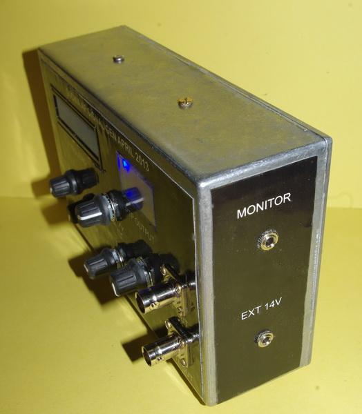
1 G0CWA ANALOG AF/MF SIGNAL GENERATOR APRIL 2013 INTRODUCTION Hi here is my design for a simple easily customizable signal generator generating variable levels of sin, triangular and square wave signals for setting up of filters etc with the added bonus of a 5v TTL compatible clock signal all from 3Hz up to around 200KHz. The whole unit is powered by either two PP3 9 volt batteries or, preferably, because of the relatively high current consumption a cheap (12V 200mA or higher) unregulated power supply. The cheap 12V wall wart types give around 15V+ peak. Any supply greater than 14V to up to around 20V will do as the onboard regulators will take care of it. I apologise for using an out of date chip for the design the ICL8038 although now out of production is still easily available on e-bay or via a lot of component suppliers as it was a very popular chip. Take care though as you should expect to pay no more than 4.00 probably a lot less I got some from Hong Kong for 1.00 each, some people are asking for up
2 to 50.00, yes At present there is no SMT equivalent available. I chose this route rather than a DDS approach because it is far easier to reproduce as a one off home brew project. Although for best performance ideally a split rail power supply should be used, a cheap split rail supply was not easily available so I designed the circuit by several simple fiddles to run on a single rail with an onboard synthetic Ground. BROAD SPECIFICATION Power supply either 2x 9volt batteries internal or an external DC of 14-20V Frequency coverage 2Hz to around 200KHz in 6 switched ranges Range no Frequency Hz K 2.3K - 43K 5.2K - 100K 12K - 210K Sin ok ok xover distortion compression compression compression Triangle ok ok ok "rounding" "rounding" "rounding" Square ok ok ok "rounding" rising distortion rising distortion TTl ok ok ok "rounding" rising distortion rising distortion Sin, Triangular and Square wave outputs of up to around 3V PTP 5V TTL compatible clock signal Optional Un-calibrated output level meter (guide to levels only) Optional Digital frequency read out Output monitor socket
3

4 MODULES The generator is built in a modular format as are most of my projects, the minimum required is the PSU and main board calibrated dials will serve the same purpose and reduce cost. The frequency meter module was bought off e-bay from jpl995 and was listed as FREQUENCY COUNTER 1HZ-80MHZ WITH 1HZ RESOLUTION I found Jim was very reliable and helpfull. Others supply similar modules but I have not dealt with them. PSU There is nothing special here just a regulator chain made up of a 7812, 7809 and 7805 the whole unit being bolted to a die-cast box which provides sufficient heat-sinking and shielding. No insulating washers were needed as the mounts are connected internally to the OV rail

")
5 PSU COMPONENT PLACEMENT PSU REAL WORLD PSU SILK SCREEN PSU TRACK (X-RAY VIEW) PSU CIRCUIT

6 MAIN BOARD Firstly an apology this board although basically the same as my prototype does have differences the major ones being on the right hand side of the board. My prototype had two extra op-amp buffers, one for the square wave signal and one for the output, I found neither were needed and removed them from the final layout, just taking the inputs to the simulated ground (5V rail). The operation of the ICL8038 chip is covered on the data sheet and is not discussed here. I have included a minimum of pre-sets to set up the board all are needed, it is not me being too lazy with the calculator to work out single resistor values. Their uses are VR1 to balance the mark space ratio of the outputs VR2 and 3 to vary the gain of the sin and triangle waveform buffers to prevent clipping of the wave forms VR13 is to optimise the sine wave shape, use a scope or the best spectrum analyser you have available, one supplied by nature, your ears, for the cleanest signal. The final two VR4 and VR8 control the frequency span control voltage and will be roughly 2/3 of the pos supply i.e. 8V to near full rail. Please note if the control high voltage is too high all sorts of distortions creep in, my prototype covered around volts but this is an SOT value and depends on the individual chip, I tried 3 different ones all needed the pots set differently for best performance. MAIN BOARD COMPONENT PLACEMENT

7 MAIN BOARD REAL WORLD MAIN BOARD SILK SCREEN MAIN BOARD TRACK (X-RAY VIEW)
8 MAIN BOARD CIRCUIT OUTPUT METER The output meter is included for giving a visual display of the output amplitude of the signals and although it works on all modes is accurate on sin waves only, even then it is not particularly accurate and is intended as an indicator only. Accurate levels would have to be measured on a scope, but, it is still a useful addition enabling quick return to values. The meter is basically a copy of my RF mv meter but tuned to operate at lower frequencies, below around 25 Hz although not giving a constant level can still be used the peak values being shown by the peak deflections of the meter. Any meter movement can be used the gain and range pre-sets VR3 and VR2 should give sufficient adjustment. It is also possible to correct for any DC offsets using VR4. R5 is an optional component and is included for meter matching to the circuit if the meter is too sensitive, it is an SOT value. The final pot VR1 is used to adjust the biasing of the diode D1 to just conduct with no input signal adjust it till a very low dc voltage can be measured at the junction of D1, C6 and VR2, the lower the better.

9 OUTPUT METER COMPONENT PLACEMENT OUTPUT METER REAL WORLD OUTPUT METER SILK SCREEN
10 OUTPUT METER TRACK (X-RAY VIEW) OUTPUT METER CIRCUIT Parts sources The frequency meter off e-bay from jpl995 and was listed as FREQUENCY COUNTER 1HZ- 80MHZ WITH 1HZ RESOLUTION The ICL8038 although now out of production is still easily available on e-bay or via a lot of component suppliers, but watch the price, don t pay more than around 4.00 maximum. All the rest of the parts are standard ones and should be easily available This again was built to replace my original unit liberated by my friend who at the moment is building up his test equipment. Hope you find this of use and happy oscillating 73 for now de Nick G0CWA. Any comments will be gratefully received and as usual I can be contacted by at n.strong@hotmail.co.uk or via the Radio Board and QRZ forums as G0CWA. I cannot guarantee to see your questions if posted elsewhere REMEMBER TO CHECK THE PCB TRACK LAYOUTS AND MIRROR THEM IF NEEDED. I HAVE PRESENTED THEM AS X-RAY VIEWS OF THE FINAL BOARD!!!! PLEASE NOTE if you downloaded this document from anywhere but
11 or I can not guarantee you will have the latest version, Please inform Dave if it was downloaded from another site. Dave s site is the ONLY ONE I HAVE AUTHORISED to distribute/display my projects and documents. However links to the projects are permitted with Daves permission. I do not supply kits, parts, PCB's or build boards for my projects but am more than willing to help talk you through a build or fault finding via my normal contact methods, or even SKYPE if required for direct contact.
GRID DIP METER DESIGN
 GRID DIP METER DESIGN BY G0CWA MAY 2013 This, my next offering of test equipment is an exceptionally useful item of test equipment with many uses, some are listed below. To coin a phrase given to me by
G0CWA Mk2 RTL SDR RADIO SEPTEMBER 2012
 G0CWA Mk2 RTL SDR RADIO SEPTEMBER 2012 For use with RTL2832U-based DVB-T USB dongle with the Elonics E4000 tuner Hi, welcome to my latest project my improved version of my SDR radio. This is based on my
Chapter 13: Comparators
 Chapter 13: Comparators So far, we have used op amps in their normal, linear mode, where they follow the op amp Golden Rules (no input current to either input, no voltage difference between the inputs).
DIY Function Generator XR2206
 DIY Function Generator XR2206 20Hz 100KHz http://radiohobbystore.com Components List: Resistors: R1, R2 1% Metal Film 5K1 R4 1% Metal Film 10K R5 1% Metal Film 3K R10 5% Carbon Film 10R R3, R9 Potentiometer
EE 368 Electronics Lab. Experiment 10 Operational Amplifier Applications (2)
") EE 368 Electronics Lab Experiment 10 Operational Amplifier Applications (2) 1 Experiment 10 Operational Amplifier Applications (2) Objectives To gain experience with Operational Amplifier (Op-Amp). To
EE 368 Electronics Lab Experiment 10 Operational Amplifier Applications (2) 1 Experiment 10 Operational Amplifier Applications (2) Objectives To gain experience with Operational Amplifier (Op-Amp). To
HIGH FREQUENCY WAVEFORM GENERATOR. Author: Carlos Rodríguez Hernández
 HIGH FREQUENCY WAVEFORM GENERATOR Author: Carlos Rodríguez Hernández ABSTRAD This Project comes from the necessity of getting a wave generator with a bandwidth over 10 Mhz and an harmonic distortion under
EE4902 C Lab 5 MOSFET Common Source Amplifier with Active Load Bandwidth of MOSFET Common Source Amplifier: Resistive Load / Active Load
 EE4902 C200 - Lab 5 MOSFET Common Source Amplifier with Active Load Bandwidth of MOSFET Common Source Amplifier: Resistive Load / Active Load PURPOSE: The primary purpose of this lab is to measure the
I'm guessing this is what has made it so no one else could get the circuit to work, I hope this helps.
 Incase I did not mention this else where, the basis of my system to provide random audio bits which the spirits can use to form their voices. The audio bits are from randomly tuning a voltage tunable AM
Lab 5: FET circuits. 5.1 FET Characteristics
 Lab 5: FET circuits Reading: The Art of Electronics (TAOE) Section 3.01 3.10, FET s, followers, and current sources. Specifically look at information relevant to today s lab: follower, current source,
6.101 Introductory Analog Electronics Laboratory
 6.101 Introductory Analog Electronics Laboratory Spring 2015, Instructor Gim Hom Project Proposal Transmitting, Receiving, and Interpreting ECG Waveforms Daniel Moon (dhmoon@mit.edu) Thipok (Ben) Rak-amnouykit
Assembly Manual for VFO Board 2 August 2018
 Assembly Manual for VFO Board 2 August 2018 Parts list (Preliminary) Arduino 1 Arduino Pre-programmed 1 Faceplate Assorted Header Pins Full Board Rev A 10 104 capacitors 1 Rotary encode with switch 1 5-volt
DESIGN OF AN ANALOG FIBER OPTIC TRANSMISSION SYSTEM
 DESIGN OF AN ANALOG FIBER OPTIC TRANSMISSION SYSTEM OBJECTIVE To design and build a complete analog fiber optic transmission system, using light emitting diodes and photodiodes. INTRODUCTION A fiber optic
Capacitive Touch Sensing Tone Generator. Corey Cleveland and Eric Ponce
 Capacitive Touch Sensing Tone Generator Corey Cleveland and Eric Ponce Table of Contents Introduction Capacitive Sensing Overview Reference Oscillator Capacitive Grid Phase Detector Signal Transformer
Injection Molding Machine Temperature Controller
 Injection Molding Machine Temperature Controller By Copyleft protects this document 1. Due to a bug between Word and Open Office, I am unable to turn off this highlighting. Hopefully it is still readable
The Walford Electronics Ford Receiver Kit Project Construction Manual
 The Walford Electronics Ford Receiver Kit Project Construction Manual Walford Electronics Ford Receiver construction manual V1.5 Page 1 of 22 Introduction The Ford receiver has four stages: The first stage
Physics 309 Lab 3 Bipolar junction transistor
 Physics 39 Lab 3 Bipolar junction transistor The purpose of this third lab is to learn the principles of operation of a bipolar junction transistor, how to characterize its performances, and how to use
LLS - Introduction to Equipment
 Published on Advanced Lab (http://experimentationlab.berkeley.edu) Home > LLS - Introduction to Equipment LLS - Introduction to Equipment All pages in this lab 1. Low Light Signal Measurements [1] 2. Introduction
An Electronic Variable Load by Dave Chute, KG4BZW
 EDITOR: GEOFF HAINES, N1GY Published Quarterly N1GY@ARRL.NET Summer Edition FROM THE EDITOR: Once again I am happy to report that we have several great articles in the Summer Edition of The WCF Experimenter.
Construction notes for the symmetrical 400 watt amplifier
 Construction notes for the symmetrical 400 watt amplifier Introduction The symmetrical amplifier is an update of one of my designs, which appeared in the Australian electronics magazine Silicon Chip in
Overview of the MSA 12/30/10
 Overview of the MSA 12/30/10 Introduction The purpose of this document is to provide an overview of the capabilities and construction of the MSA to help potential builders get oriented. Much more detailed
Optical Theremin Critical Design Review Yanzhe Zhao, Mason Story, Nicholas Czesak March
 Optical Theremin Critical Design Review Yanzhe Zhao, Mason Story, Nicholas Czesak March-07-2015 Abstract A theremin is a musical instrument whose tone and pitch can be controlled without physical contact.
THE INTERMEDIATE VFO
 THE INTERMEDIATE VFO Some Intermediate tutors have reported difficulties in either obtaining parts for the RSGB Intermediate textbook VFO or in getting the VFO going once they have the parts. This alternative
2600 VCO Operation Manual
 2600 VCO Operation Manual Introduction 3 General 3 About power supply and buffering 3 Features 3 Technical Specifications 3 Core Operation 4 Panel Layout 4 Controllers and inputs/outputs 4 Controllers
Using Circuits, Signals and Instruments
 Using Circuits, Signals and Instruments To be ignorant of one s ignorance is the malady of the ignorant. A. B. Alcott (1799-1888) Some knowledge of electrical and electronic technology is essential for
ECE 220 Laboratory 3 Thevenin Equivalent Circuits, Constant Current Source, and Inverting Amplifier
 ECE 220 Laboratory 3 Thevenin Equivalent Circuits, Constant Current Source, and Inverting Amplifier Michael W. Marcellin The first portion of this document describes preparatory work to be completed in
Experiment # (3) PCM Modulator
 PCM Modulator") Islamic University of Gaza Faculty of Engineering Electrical Department Experiment # (3) PCM Modulator Digital Communications Lab. Prepared by: Eng. Mohammed K. Abu Foul Experiment Objectives: 1. To understand
Islamic University of Gaza Faculty of Engineering Electrical Department Experiment # (3) PCM Modulator Digital Communications Lab. Prepared by: Eng. Mohammed K. Abu Foul Experiment Objectives: 1. To understand
Low Cost Screening Audiometer
 Abstract EE 389 EDL Report, EE Dept. IIT Bombay, submitted on Nov.2004 Low Cost Screening Audiometer Group No.: D3 Chirag Jain 01d07018 Prashant Yadav 01d07024 Puneet Parakh 01d07007 Supervisor: Prof.
Physics 120 Lab 1 (2018) - Instruments and DC Circuits
 - Instruments and DC Circuits") Physics 120 Lab 1 (2018) - Instruments and DC Circuits Welcome to the first laboratory exercise in Physics 120. Your state-of-the art equipment includes: Digital oscilloscope w/usb output for SCREENSHOTS.
Physics 120 Lab 1 (2018) - Instruments and DC Circuits Welcome to the first laboratory exercise in Physics 120. Your state-of-the art equipment includes: Digital oscilloscope w/usb output for SCREENSHOTS.
For the filter shown (suitable for bandpass audio use) with bandwidth B and center frequency f, and gain A:
 with bandwidth B and center frequency f, and gain A:") Basic Op Amps The operational amplifier (Op Amp) is useful for a wide variety of applications. In the previous part of this article basic theory and a few elementary circuits were discussed. In order to
Basic Op Amps The operational amplifier (Op Amp) is useful for a wide variety of applications. In the previous part of this article basic theory and a few elementary circuits were discussed. In order to
E-200D ALIGNMENT. See the end of the procedure for the location of the calibration points. EQUIPMENT REQUIRED
 E-200D ALIGNMENT NOTE: This is not an official B&K alignment procedure. This procedure was created by experimenting with an E-200D. However when this procedure is followed, the resulting calibration should
A Simple Notch Type Harmonic Distortion Analyzer
 by Kenneth A. Kuhn Nov. 28, 2009, rev. Nov. 29, 2009 Introduction This note describes a simple notch type harmonic distortion analyzer that can be constructed with basic parts. It is intended for use in
ASSEMBLY MANUAL FOR R3500D DIRECTION FINDING RECEIVER KIT
 SDR-Kits www.sdr-kits.net SDR-Kits is CRKITS Authorised Distributor for Europe ASSEMBLY MANUAL FOR R3500D DIRECTION FINDING RECEIVER KIT Rev. A May 24, 2015 Written by CRKITS http://www.crkits.com Thanks
When you have completed this exercise, you will be able to relate the gain and bandwidth of an op amp
 Op Amp Fundamentals When you have completed this exercise, you will be able to relate the gain and bandwidth of an op amp In general, the parameters are interactive. However, in this unit, circuit input
Wiring Manual NEScaf April 2010 (August 2006)
") Wiring Manual NEScaf April 2010 (August 2006) Switched Capacitor Audio Filter The NEScaf is a switched capacitor audio filter (acronym SCAF) built around a building-block type filter chip. The NEScaf will
Wiring Manual NEScaf April 2010 (August 2006) Switched Capacitor Audio Filter The NEScaf is a switched capacitor audio filter (acronym SCAF) built around a building-block type filter chip. The NEScaf will
Through-Zero VoltageControlled Oscillator
 Through-Zero VoltageControlled Oscillator Liivatera OÜ Rävala pst. 8, A211 10143 Tallinn Harjumaa Estonia T: +372 637 6441 T: +44 5603 010854 E: contact@liivatera.com Through- Zero VCO Manual 0.1 1 Contents
SIMPLE DIRECT DRIVE DESULPHATOR/ DESULFATOR KIT INSTRUCTIONS
 SIMPLE DIRECT DRIVE DESULPHATOR/ DESULFATOR KIT INSTRUCTIONS Parts List C1 470uF/ 25V 1off C2 C5 0.1uF/ 50V 4off C6 C9 0.01uF/ 50V 4off D1 12V/ 1.3W zener 1off Q1 2N2907 1off Q2 Q4 IRFB3307 3off R1 510R/
SE4 DSP + High Performance Professional Digital Stereo Encoder With DSP Filters
 PCS Electronics www.pcs-electronics.com info@pcs-electronics.com SE4 DSP + High Performance Professional Digital Stereo Encoder With DSP Filters SE4 DSP + without the LCD control module (connects to black
MM5452 MM5453 Liquid Crystal Display Drivers
 MM5452 MM5453 Liquid Crystal Display Drivers General Description The MM5452 is a monolithic integrated circuit utilizing CMOS metal gate low threshold enhancement mode devices It is available in a 40-pin
Lab 12: FollowBot. Christopher Agostino Lab Partner: MacCallum Robertson May 12, 2015
 Lab 12: FollowBot Christopher Agostino Lab Partner: MacCallum Robertson May 12, 2015 Introduction For the great 111 final project challenge, my partner and I decided we would attempt to design a simple
PHYSICS 107 LAB #9: AMPLIFIERS
 Section: Monday / Tuesday (circle one) Name: Partners: PHYSICS 107 LAB #9: AMPLIFIERS Equipment: headphones, 4 BNC cables with clips at one end, 3 BNC T connectors, banana BNC (Male- Male), banana-bnc
RF Generators. Requirements:
 Requirements: RF Generators to deliver a requested forward power (adjustable) level into an RF system power level is adjusted manually, or power level is controlled by a digital or analog input signal
Sweep / Function Generator User Guide
 I. Overview Sweep / Function Generator User Guide The Sweep/Function Generator as developed by L. J. Haskell was designed and built as a multi-functional test device to help radio hobbyists align antique
ECE Lab #4 OpAmp Circuits with Negative Feedback and Positive Feedback
 ECE 214 Lab #4 OpAmp Circuits with Negative Feedback and Positive Feedback 20 February 2018 Introduction: The TL082 Operational Amplifier (OpAmp) and the Texas Instruments Analog System Lab Kit Pro evaluation
EE 3305 Lab I Revised July 18, 2003
 Operational Amplifiers Operational amplifiers are high-gain amplifiers with a similar general description typified by the most famous example, the LM741. The LM741 is used for many amplifier varieties
User Guide V
 XV User Guide V1.10 25-02-2017 Diode Ladder Wave Filter Thank you for purchasing the AJH Synth Sonic XV Eurorack synthesiser module, which like all AJH Synth products, has been designed and handbuilt in
H BRIDGE INVERTER. Vdc. Corresponding values of Va and Vb A+ closed, Va = Vdc A closed, Va = 0 B+ closed, Vb = Vdc B closed, Vb = 0 A+ B+ A B
 1. Introduction How do we make AC from DC? Answer the H-Bridge Inverter. H BRIDGE INVERTER Vdc A+ B+ Switching rules Either A+ or A is always closed, but never at the same time * Either B+ or B is always
SoftRock v6.0 Builder s Notes. May 22, 2006
 SoftRock v6.0 Builder s Notes May 22, 2006 Be sure to use a grounded tip soldering iron in building the v6.0 SoftRock circuit board. The soldering iron needs to have a small tip, (0.05-0.1 inch diameter),
Euro Rack Series. Classic VCA. User Manual. Oakley Sound Systems. Discrete Core Voltage Controlled Amplifier V2.3
 Oakley Sound Systems Euro Rack Series Classic VCA Discrete Core Voltage Controlled Amplifier User Manual V2.3 Tony Allgood Oakley Sound Systems CARLISLE United Kingdom Introduction This is the User Manual
Multiple Instrument Station Module
 Multiple Instrument Station Module Digital Storage Oscilloscope Vertical Channels Sampling rate Bandwidth Coupling Input impedance Vertical sensitivity Vertical resolution Max. input voltage Horizontal
Sensor Comparator. Fiendish objects
 Part α: Building a simple Sensor Comparator : Step 1: Locate the following circuit parts from your bag. Part Number Fiendish objects Part name 1 Wire Kit: Contains wires. 3 10kΩ Resistor 9 Photodetector
Sapphire Instruments Co., Ltd. Calibration Procedure of SI-9101
 Sapphire Instruments Co., Ltd. Calibration Procedure of SI-9101 1. How to open the case, please follow the steps. 1.1 Remove the battery lid. 1.2 You will see the two screws and loosen them. Fig. 1 1.3
MM5452/MM5453 Liquid Crystal Display Drivers
 MM5452/MM5453 Liquid Crystal Display Drivers General Description The MM5452 is a monolithic integrated circuit utilizing CMOS metal gate, low threshold enhancement mode devices. It is available in a 40-pin
University of Utah Electrical Engineering Department ECE 2100 Experiment No. 2 Linear Operational Amplifier Circuits II
 University of Utah Electrical Engineering Department ECE 2100 Experiment No. 2 Linear Operational Amplifier Circuits II Minimum required points = 51 Grade base, 100% = 85 points Recommend parts should
Single Conversion LF Upconverter Andy Talbot G4JNT Jan 2009
 Single Conversion LF Upconverter Andy Talbot G4JNT Jan 2009 Mark 2 Version Oct 2010, see Appendix, Page 8 This upconverter is designed to directly translate the output from a soundcard from a PC running
IPR LA-3 KIT last update 15 march 06
 IPR LA-3 KIT last update 15 march 06 PART-2: Audio Circuitry CIRCUIT BOARD LAYOUT: Power and Ground Distribution Now that your power supply is functional, it s time to think about how that power will be
nonlinearcircuits QUO/LPF build notes version 2 11 April 2014
 nonlinearcircuits QUO/LPF build notes version 2 11 April 2014 This circuit is based on the 4 pole LPF in Electronotes 41, tho has been subject to a number of tweaks and prods to bring it to where it is
ELEG 205 Analog Circuits Laboratory Manual Fall 2016
 ELEG 205 Analog Circuits Laboratory Manual Fall 2016 University of Delaware Dr. Mark Mirotznik Kaleb Burd Patrick Nicholson Aric Lu Kaeini Ekong 1 Table of Contents Lab 1: Intro 3 Lab 2: Resistive Circuits
EOSC10KV3 USER MANUAL Ultra-pure reference oscillator (from AN67 from Linear-Technology) Contents
 Contents") EOSC10KV3 USER MANUAL Ultra-pure reference oscillator (from AN67 from Linear-Technology) EOSC10KV3_Manual.odt OnEAudioProjects contact@oneaudio.net www.oneaudio.net Document Revision Date Modifications
EOSC10KV3 USER MANUAL Ultra-pure reference oscillator (from AN67 from Linear-Technology) EOSC10KV3_Manual.odt OnEAudioProjects contact@oneaudio.net www.oneaudio.net Document Revision Date Modifications
Simple LFO Features. 2. Application. 3. Description. Simple and easy to build LFO module for Analog Synthesizers.
 Simple LFO. Simple and easy to build LFO module for Analog Synthesizers.. Features Square and Triangle waveforms (90 phase shifted) Dual range frequencies Frequency ranges from under Hz up to several khz
ETEK TECHNOLOGY CO., LTD.
 Trainer Model: ETEK DCS-6000-07 FSK Modulator ETEK TECHNOLOGY CO., LTD. E-mail: etek21@ms59.hinet.net mlher@etek21.com.tw http: // www.etek21.com.tw Digital Communication Systems (ETEK DCS-6000) 13-1:
Testing and Stabilizing Feedback Loops in Today s Power Supplies
 Keywords Venable, frequency response analyzer, impedance, injection transformer, oscillator, feedback loop, Bode Plot, power supply design, open loop transfer function, voltage loop gain, error amplifier,
Physics 364, Fall 2014, Lab #12 (transistors I: emitter follower) Monday, October 13 (section 401); Tuesday, October 14 (section 402)
 Monday, October 13 (section 401); Tuesday, October 14 (section 402)") Physics 364, Fall 2014, Lab #12 Name: (transistors I: emitter follower) Monday, October 13 (section 401); Tuesday, October 14 (section 402) Course materials and schedule are at positron.hep.upenn.edu/p364
Physics 364, Fall 2014, Lab #12 Name: (transistors I: emitter follower) Monday, October 13 (section 401); Tuesday, October 14 (section 402) Course materials and schedule are at positron.hep.upenn.edu/p364
1 TRANSISTOR CIRCUITS
 FM TRANSMITTERS The first group of circuits we will discuss are FM TRANSMITTERS. They can be called SPY TRANSMITTERS, FM BUGS, or a number of other interesting names. They all do the same thing. They transmit
PowerAmp Design. PowerAmp Design PAD541 COMPACT POWER OP AMP
 PowerAmp Design COMPACT POWER OP AMP Rev E KEY FEATURES LOW COST HIGH VOLTAGE 00 VOLTS HIGH OUTPUT CURRENT 5 AMPS 50 WATT DISSIPATION CAPABILITY 00 WATT OUTPUT CAPABILITY 0.63 HEIGHT SIP DESIGN APPLICATIONS
ECE4902 C Lab 5 MOSFET Common Source Amplifier with Active Load Bandwidth of MOSFET Common Source Amplifier: Resistive Load / Active Load
 ECE4902 C2012 - Lab 5 MOSFET Common Source Amplifier with Active Load Bandwidth of MOSFET Common Source Amplifier: Resistive Load / Active Load PURPOSE: The primary purpose of this lab is to measure the
UDB12x. 2xxS. xs seriers. Signal Generator. Manual. Users
 UDB12x 2xxS xs seriers Direct Digital Synthesis (DDS) Signal Generator Users Manual Introduction of the instrument This series direct digital synthesis signal generator use DDS technology and FPGA design
Lab #7: Transient Response of a 1 st Order RC Circuit
 Lab #7: Transient Response of a 1 st Order RC Circuit Theory & Introduction Goals for Lab #7 The goal of this lab is to explore the transient response of a 1 st Order circuit. In order to explore the 1
FY10xx(S) series Direct Digital Synthesis (DDS) Signal Generator Users Manual Rev
 series Direct Digital Synthesis (DDS) Signal Generator Users Manual Rev") FY10xx(S) series Direct Digital Synthesis (DDS) Signal Generator Users Manual Rev2.3 2011-5-10 Introduction of the instrument FY10xx(FY10xxS) series direct digital synthesis signal generator use DDS technology
FY10xx(S) series Direct Digital Synthesis (DDS) Signal Generator Users Manual Rev2.3 2011-5-10 Introduction of the instrument FY10xx(FY10xxS) series direct digital synthesis signal generator use DDS technology
PulsePuppy Installation and Operation Manual Oscillator Carrier Revised: 30 January TAPR
 PulsePuppy Installation and Operation Manual Oscillator Carrier Revised: 30 January 2018 2018 TAPR Introduction The PulsePuppy is a carrier board for small user-provided oven controlled ( OCXO ) and temperature
APPENDIX D DISCUSSION OF ELECTRONIC INSTRUMENTS
 APPENDIX D DISCUSSION OF ELECTRONIC INSTRUMENTS DC POWER SUPPLIES We will discuss these instruments one at a time, starting with the DC power supply. The simplest DC power supplies are batteries which
Learning Objectives:
 Learning Objectives: At the end of this topic you will be able to; recall the conditions for maximum voltage transfer between sub-systems; analyse a unity gain op-amp voltage follower, used in impedance
ALX-SSB 5 Band Filter Assembly Manual 19 November 2018
 ALX-SSB 5 Band Filter Assembly Manual 19 November 2018 Contents Theory of Operation:... 1 Figure 1... 2 Parts Included:... 4 Board Overview:... 5 Figure 2... 5 Figure 3... 5 Board Assembly:... 6 Cable
EXPERIMENT 2.2 NON-LINEAR OP-AMP CIRCUITS
 2.16 EXPERIMENT 2.2 NONLINEAR OPAMP CIRCUITS 2.2.1 OBJECTIVE a. To study the operation of 741 opamp as comparator. b. To study the operation of active diode circuits (precisions circuits) using opamps,
Knight Kit V44 VFO Stabilized by the Cumbria Design X-Lock 3.0
 Knight Kit V44 VFO Stabilized by the Cumbria Design X-Lock 3.0 The Knight V44 VFO has a place in history. It was designed in the late 1950 s as a self contained VFO intended to plug into the crystal socket
DEM Part Number L144-28INTCK 144 MHz Transverter Kit and complete kit
 DEM Part Number L144-28INTCK 144 MHz Transverter Kit and complete kit Power Out: Noise Figure and Gain: DC Power Requirement: 50 mw linear minimum 3.5 db NF nominal, 5 dbg maximum 12-15.5 VDC, 13.8 nominal
VCO Design Project ECE218B Winter 2011
 VCO Design Project ECE218B Winter 2011 Report due 2/18/2011 VCO DESIGN GOALS. Design, build, and test a voltage-controlled oscillator (VCO). 1. Design VCO for highest center frequency (< 400 MHz). 2. At
DEPARTMENT OF ELECTRICAL ENGINEERING AND COMPUTER SCIENCE MASSACHUSETTS INSTITUTE OF TECHNOLOGY CAMBRIDGE, MASSACHUSETTS 02139
 DEPARTMENT OF ELECTRICAL ENGINEERING AND COMPUTER SCIENCE MASSACHUSETTS INSTITUTE OF TECHNOLOGY CAMBRIDGE, MASSACHUSETTS 019 Spring Term 00.101 Introductory Analog Electronics Laboratory Laboratory No.
Analog Synthesizer: Functional Description
 Analog Synthesizer: Functional Description Documentation and Technical Information Nolan Lem (2013) Abstract This analog audio synthesizer consists of a keyboard controller paired with several modules
Audio Amplifier. November 27, 2017
 Audio Amplifier November 27, 2017 1 Pre-lab No pre-lab calculations. 2 Introduction In this lab, you will build an audio power amplifier capable of driving a 8 Ω speaker the way it was meant to be driven...
Connecting the FCC-2 to the Hendricks DC Kits Bob Okas, W3CD
 Connecting the FCC-2 to the Hendricks DC Kits Bob Okas, W3CD This is an application note that describes how you can connect the NorCal FCC-1/2 combination to the DC kits. It involves a few extra components
Optical Attenuation Sensor for Process Control
 Optical Attenuation Sensor for Process Control Senior Project Final Report Eric Borisch Jeremy Protas Scott Ruppert Christopher Spiek EEAP 398/399 April 16, 1999 Advisor: Dr. Frank Merat Executive Summary
Homebrew and Experimenters Group HF Inductance Bridge (Compiled by VK2TOX)
") Homebrew and Experimenters Group HF Inductance Bridge (Compiled by VK2TOX) There are a number of ways to measure inductances used in construction of RF equipment. One of the most versatile ways is with
Homebrew and Experimenters Group HF Inductance Bridge (Compiled by VK2TOX) There are a number of ways to measure inductances used in construction of RF equipment. One of the most versatile ways is with
Definitions. Spectrum Analyzer
 SIGNAL ANALYZERS Spectrum Analyzer Definitions A spectrum analyzer measures the magnitude of an input signal versus frequency within the full frequency range of the instrument. The primary use is to measure
10: AMPLIFIERS. Circuit Connections in the Laboratory. Op-Amp. I. Introduction
 10: AMPLIFIERS Circuit Connections in the Laboratory From now on you will construct electrical circuits and test them. The usual way of constructing circuits would be to solder each electrical connection
CompuLign User Guide - V2.0
 CompuLign User Guide - V2.0 I. Overview The CompuLign computer driven alignment tool as developed by L. J. Haskell was designed and built as a multi-functional test device to help radio hobbyists align
TG550 AIM & THURLBY THANDAR INSTRUMENTS. 5MHz function generator with sweep
 AIM & THURLBY THANDAR INSTRUMENTS TG550 5MHz function generator with sweep simultaneous display of frequency & amplitude crystal controlled digital frequency locking seven digit external frequency counter
SGM ns, Low-Power, 3V/5V, Rail-to-Rail Input Single-Supply Comparator
 45ns, Low-Power, 3V/5V, Rail-to-Rail GENERAL DESCRIPTION The is a single high-speed comparator optimized for systems powered from a 3V or 5V supply. The device features high-speed response, low-power consumption,
OPERATIONAL AMPLIFIERS LAB
 1 of 6 BEFORE YOU BEGIN PREREQUISITE LABS OPERATIONAL AMPLIFIERS LAB Introduction to Matlab Introduction to Arbitrary/Function Generator Resistive Circuits EXPECTED KNOWLEDGE Students should be familiar
DEPARTMENT OF ELECTRICAL ENGINEERING AND COMPUTER SCIENCE MASSACHUSETTS INSTITUTE OF TECHNOLOGY CAMBRIDGE, MASSACHUSETTS 02139
 DEPARTMENT OF ELECTRICAL ENGINEERING AND COMPUTER SCIENCE MASSACHUSETTS INSTITUTE OF TECHNOLOGY CAMBRIDGE, MASSACHUSETTS 019.101 Introductory Analog Electronics Laboratory Laboratory No. READING ASSIGNMENT
V d = "1" if V in > V m. Fig 2: Frequency analysis of the PDM signal. Fig 1: PDM signal generation
 A low voltage CMOS Pulse Duration Modulator Meena Ramani,Ashok Verma, Dr. John G Harris Dept. of Electrical & Computer Engineering University of Florida, Gainesville, FL 32611, USA Email: meena@cnel.ufl.edu,
St.MARTIN S ENGINEERING COLLEGE
 St.MARTIN S ENGINEERING COLLEGE Dhulapally, Kompally, Secunderabad-500014. Branch Year&Sem Subject Name : Electrical and Electronics Engineering : III B. Tech I Semester : IC Applications OBJECTIVES QUESTION
Lab 7: DELTA AND SIGMA-DELTA A/D CONVERTERS
 ANALOG & TELECOMMUNICATION ELECTRONICS LABORATORY EXERCISE 6 Lab 7: DELTA AND SIGMA-DELTA A/D CONVERTERS Goal The goals of this experiment are: - Verify the operation of a differential ADC; - Find the
HAMTRONICS TB901 FM EXCITER INSTALLATION, OPERATION, & MAINTENANCE
 HAMTRONICS TB901 FM EXCITER INSTALLATION, OPERATION, & MAINTENANCE GENERAL INFORMATION. The TB901 is a single-channel low power fm transmitter (exciter) designed to provide 300-600 milliwatts continuous
Electric Druid Tap Tempo LFO
 Electric Druid Tap Tempo LFO Introduction 2 Features 3 Simple Tap Tempo control 3 Ability to synchronize LFO to external clocks 3 LFO range from 0.025Hz to above 50Hz 3 Sixteen output waveforms, in two
DIGITAL ELECTRONICS WAVE SHAPING AND PULSE CIRCUITS. September 2012
 AM 5-403 DIGITAL ELECTRONICS WAVE SHAPING AND PULSE CIRCUITS September 2012 DISTRIBUTION RESTRICTION: Approved for public release. Distribution is unlimited. DEPARTMENT OF THE ARMY MILITARY AUXILIARY RADIO
3-Way Active Crossover Model XOVER-3. Xkitz.com. User s Manual. Features. Rev 2.1
 3-Way Active Crossover Model XOVER-3 User s Manual Rev 2.1 Xkitz.com Features 3-way Active Crossover for driving separate subwoofer, midrange and tweeter amplifiers Linkwitz-Riley crossover, 4 th order,
Updating KK7B, SHF,DEM or DEMI 900 and 1296 MHz. transverters
 Updating KK7B, SHF,DEM or DEMI 900 and 1296 MHz. transverters By Steve Kostro, N2CEI PREFACE: Yes, It may be hard to believe, but the original 900 and 1296 No-Tune transverter concepts have been around
GF 467F FUNCTION GENERATOR. PROTECTED RS232 + (USB OR LAN)* LabVIEW 0,01 Hz to 5 MHz CMos. Specifications. Other specifications
* LabVIEW 0,01 Hz to 5 MHz CMos. Specifications. Other specifications") FUNCTION GENERATOR EAN CODE : 3760244880468 5 MHZ+RS232++(USB or LAN)* GF 467F COMPLETE : Reciprocal frequency counter 50 MHz. - Internal linear or logarithmic sweep, and external VCF or FM modulation.
FUNCTION GENERATOR EAN CODE : 3760244880468 5 MHZ+RS232++(USB or LAN)* GF 467F COMPLETE : Reciprocal frequency counter 50 MHz. - Internal linear or logarithmic sweep, and external VCF or FM modulation.
University of North Carolina, Charlotte Department of Electrical and Computer Engineering ECGR 3157 EE Design II Fall 2009
 University of North Carolina, Charlotte Department of Electrical and Computer Engineering ECGR 3157 EE Design II Fall 2009 Lab 1 Power Amplifier Circuits Issued August 25, 2009 Due: September 11, 2009
ericssonz LBI-38640E MAINTENANCE MANUAL FOR VHF TRANSMITTER SYNTHESIZER MODULE 19D902780G1 DESCRIPTION
 MAINTENANCE MANUAL FOR VHF TRANSMITTER SYNTHESIZER MODULE 19D902780G1 TABLE OF CONTENTS Page DESCRIPTION........................................... Front Cover GENERAL SPECIFICATIONS...................................