Analog Transmission System
|
|
|
- Shona Blake
- 5 years ago
- Views:
Transcription
1 Analog Transmission System
2 Q ช องทางการส งส ญญาณแบบใดล ะ ถ อว าเป นช องส งส ญญาณ Analog A ช อง wire หร อ wirelss น า

")
3 Analog Transmission Media WIRE สายโทรศ พท (ADSL,VDSL) Coaxial Cable (DOCSIS)


4 Analog Transmission Media WIRELESS
5 Q แล วด อย างไรล ะว าเป นช องส ง ส ญญาณ Analog
6 Bandpass Channel Most of Analog Transmission Media is Bandpass Channel Cannot transmit Digital Signal Low frequency data pattern will be all lost Need Signal Conversion

7 Q ถ าอยากส งส ญญาณ Digital ไปบน ช องส ญญาณ Analog ล ะ ทาไงด A Conversion ส

8 Signal Conversion Digital signal with inf bandwidth Analog signal with limited bandwidth
9 Q Bandwidth ของ Analog Channel ต างๆท เราใช งานจร งม น เป นย งไงบ าง
10 A Mobile Channel ก อนม ย ใกล ต วด

11 Mobile Frequency Spectrum
12 Cellular communications GSM900 (AIS) MHz (uplink) MHz (downlink) 124 RF channels (channel numbers 1 to 124) spaced at 200 khz GSM1800/CDMA1800 (DTAC/AIS/TRUE) 1,710 1,785 MHz (uplink) 1,805 1,880 MHz (downlink) 374 channels (channel numbers 512 to 885) spaced at 200 khz CDMA2100 (3G/4G)(DTAC/AIS/TRUE) 1,885-2,025 MHz (uplink) 2,110-2,200 MHz(downlink) Spaced at 5 MHz
13 A TV Channel ล ะ

14 Television Channel

15
16 A ช อง Satellite บ าง

17 Terrestrial / SATELLITE microwave
18 A ช องน ๆ Bluetooth ไง ใครๆก ใช
19 Bluetooth Operate in noisy radio frequency environments GHz GHz omni-directional Point-to-multipoint frequency-hopping scheme 79 hops (RF channels) 1 MHz apart. bandwidth is reduced in Japan, France and Spain The maximum frequency hopping rate is 1600 hops/s link range Usually 10 centimeters to 10 meters Can be extended to more than 100 meters by increasing the transmit power Small amounts of data 1Mbps over short distances (up to 10 meters).
20 A NFC: near-field communication
21 NFC: near-field communication

22 NFC: near-field communication
23 A RFID น ก เคยได ย น

24 RFID: radio frequency identification

25 A เอาอ นน ด วย ช อง WiFi


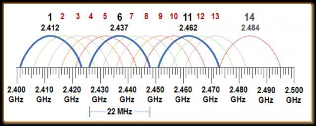
26 WiFi Band
27 A ช องว ทย (Radio Station) ล ะ


28 Radio Frequency

29 Frequency Utilization Bandwidth Limitation Transmitting Direct Digital Signal is not possible
30 Figure 5.1 Digital-to-analog conversion 5.30 Analog Selected Channel Frequency
31 Digital Modulation Digital to Analog Conversion Changing Analog Sinewave signal properties to represent digital data What sinewave properties to be changed? Amplitude Frequency Phase
32 Q แล วม นทาไงอ ะ ท ใช Analog Signal property มาเป นต วแทนข อม ล Digital A ก ทา modulation ไง


33 What property has been changed?
34 Q Modulation ม นทาไงล ะ งงอย ด A ค อม นทาได หลายแบบตาม Analog Property

35 Figure 5.2 Types of digital-to-analog conversion 5.35 เปล ยน Amplitude เปล ยน frequency เปล ยน Phase เปล ยน Amplitude & Phase
36 ASK (Amplitude Shift Keying) Changing Amplitude of channel frequency 2-ASK (Binary ASK) 0 -> A0 1 -> A1 4-ASK 00 -> A0 01 -> A1 10 -> A2 11 -> A3
37 5.37 Figure 5.3 Binary amplitude shift keying (Binary ASK, On-Off Keying (OOK) RFID/NFC Transmission

38 Figure 5.4 Implementation of binary ASK 5.38

) m(t)")
 t) =")

)] =")


39 cos cos = ½(cos ( + ) + cos ( - )) m(t) cos(2 f c t) cos(2 f c t) = ½[m(t)(cos(2 f c t+2 f c t)+cos(2 f c t-2 f c t))] = ½(m(t)(cos(4 f c t)+cos(0))) Amplitude Shift Keying
40 Signal rate / Data Rate / Bandwidth with ASK Signal rate = # signal unit / sec (baud) Data Rate = #bits/sec (bps) N = (#bits/ signal unit) x (#signal unit/s) N = r x baud N = r x S 2-ASK (OOK) r = 1 (bit/signal unit)
41 4-ASK r = 2 (bits/signal unit)
42 Signal rate / Data Rate / Bandwidth with ASK Signal rate = # signal unit / sec (baud) ข นก บ Channel Bandwidth BW = (1+d)S 0<= d <= 1 S <= BW <= 2S (BW/2) <= S <= BW
43 Example 5.3 We have an available bandwidth of 100 khz which spans from 200 to 300 khz. What are the carrier frequency and the bit rate if we modulated our data by using ASK with d = 1? Solution The middle of the bandwidth is located at 250 khz. This means that our carrier frequency can be at f c = 250 khz. We can use the formula for bandwidth to find the bit rate (with d = 1 and r = 1). N = r x S 5.43

44 Example In data communications, we normally use full-duplex links with communication in both directions. We need to divide the bandwidth into two with two carrier frequencies, as shown in Figure 5.5. The figure shows the positions of two carrier frequencies and the bandwidths. The available bandwidth for each direction is now 50 khz, which leaves us with a data rate of 25 kbps in each direction.
45 Summarize: Amplitude Shift Keying Bit representation Changing Amplitude of Carrier Signal Benefit Simple (normally used for fiber optic / RFID) Require Less Bandwidth Disadvantage Easily effected by noise
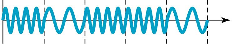
46 FSK (Frequency Shift Keying) Changing Frequency of channel frequency 2-FSK (Binary FSK) 0 -> f0 1 -> f1 4-FSK 00 -> f0 01 -> f1 10 -> f2 11 -> f3

47 Figure 5.6 Binary frequency shift keying 5.47 S <= Sub-carrier spacing (2Df) <= 2S
48 Example 5.5 We have an available bandwidth of 100 khz which spans from 200 to 300 khz. What should be the carrier frequency and the bit rate if we modulated our data by using FSK with d = 1? Solution This problem is similar to Example 5.3, but we are modulating by using FSK. The midpoint of the band is at 250 khz. We choose 2Δf to be 50 khz; this means 5.48 S <= Sub-channel spacing (2Df) <= 2S 0<= d <= 1
49 Figure 5.7 Bandwidth of MFSK used in Example
50 Example 5.6 We need to send data 3 bits at a time at a bit rate of 3 Mbps. The carrier frequency is 10 MHz. Calculate the number of levels (different frequencies), the baud rate, and the bandwidth Solution We can have L = 2^3 = 8. The baud rate is S = N/r = 3 Mbps/3 (bps / bit-per-signal unit) = 1 Mbaud. S <= sub-channel spacing <= 2S Choose d=0 -> (2Δf = S = 1 MHz) This means that the carrier frequencies must be 1 MHz apart.

51 Figure 5.8 Bandwidth of MFSK used in Example The bandwidth is B = = Figure 5.8 shows the allocation of frequencies and bandwidth.
52 PSK (Phase Shift Keying) Changing Frequency of channel frequency 2-PSK (Binary PSK) 0 -> zeta_0 1 -> zeta_1 4-PSK 00 -> zeta_0 01 -> zeta_1 10 -> zeta_2 11 -> zeta_3

53 Figure 5.9 Binary phase shift keying 5.53

54 Figure 5.10 Implementation of BPSK 5.54
; binary")


")
55 Phase Shift Keying Acos(2 fct ); binary '0' st () Acos(2 fct); binary '1' X cos( 2 f t) cos(2 f t ) C C Binary Data [0, 1] X (Digital Signal) [-1, 1] X cos(2 f t) cos(2 ft ) C C
 cos(2 C 2 C ) 2 1 X cos 4 fct X")
56 Phase Shift Keying X cos(2 f t)cos(2 f t) X f t f t f t f t C C 1 cos(2 C 2 C ) cos(2 C 2 C ) 2 1 X cos 4 fct X 2
57 Figure 5.11 QPSK and its implementation 5.57 MSB LSB Phase combination of 2 bits
58 Example Find the bandwidth for a signal transmitting at 12 Mbps for QPSK. The value of d = 0. Solution For QPSK, 2 bits is carried by one signal element. This means that r = 2. So the signal rate (baud rate) is S = N (1/r) = 6 Mbaud. With a value of d = 0, we have B = S = 6 MHz.
59 5.59 Figure 5.12 Concept of a constellation diagram
60 Example Show the constellation diagrams for an ASK (OOK), BPSK, and QPSK signals. Solution Figure 5.13 shows the three constellation diagrams.
61 Figure 5.13 Three constellation diagrams 5.61
62 DATA COMMUNICATIONS, Department of Computer Engineering, KMITL B. A. Forouzan, Data Communications and Networking, 4th Quadrature Amplitude Modulation AS K FS K PS K QA 62 M Bit representation Combination of ASK and PSK Changing Amplitude & Phase of Career Signal One bit, One signal unit Benefit Less effected by noise compared to ASK Require less bandwidth Disadvantage Complex demodulation technique
63 5.63 Note Quadrature amplitude modulation is a combination of ASK and PSK.
64 Figure 5.14 Constellation diagrams for some QAMs 5.64


65 DATA COMMUNICATIONS, Department of Computer Engineering, KMITL B. A. Forouzan, Data Communications and Networking, 4th Quadrature Amplitude Modulation AS K FS K PS K QA 65 M Quadrature amplitude modulation is a combination of ASK and PSK.

66 Quadrature Amplitude Modulation

67 Quadrature Amplitude Modulation ITU-T recommendation OSI recommendation
68 Quadrature Amplitude Modulation
![Quadrature Amplitude Modulation 11 01 00 10 01 X cos(2 fct) Y sin(2 fct) cos Bcos A sinbsin A cos( A B) X Binary Data [0, 1] + )) X (Digital Signal) [-1, 1] Y Binary Data [0, 1] Y (Digital Signal)](/docs-images/96/128298987/images/69-0.jpg "[-1, 1] Xcos + Ysin cos cos +sin sin =cos( - ) 0-1 0-1 -1 cos + -1 sin cos( +135) -135 0-1 1 1-1 cos + 1 sin cos( -135) +135 1 1 0-1 1 cos + -1 sin cos( +45) -45 1 1 1 1 1 cos + 1 sin cos( -45)")
69 Quadrature Amplitude Modulation X cos(2 fct) Y sin(2 fct) cos Bcos A sinbsin A cos( A B) X Binary Data [0, 1] + )) X (Digital Signal) [-1, 1] Y Binary Data [0, 1] Y (Digital Signal) [-1, 1] Xcos + Ysin cos cos +sin sin =cos( - ) cos + -1 sin cos( +135) cos + 1 sin cos( -135) cos + -1 sin cos( +45) cos + 1 sin cos( -45) +45
=(0,0) x=0=>-a -Acos( ) X cos(2")
 Acos( ) y=0=>-a -Asin( ) *")
70 Quadrature Amplitude Modulation (x,y)=(0,0) x=0=>-a -Acos( ) X cos(2 f t) Y sin(2 f t) C C Asin( ) A -Acos( ) Acos( ) y=0=>-a -Asin( ) * (0,0) -Asin( )
71 QAM X cos(2 f t) Ysin(2 f t) cos(2 f t) C C C X cos(2 fct)cos(2 fct) Y sin(2 fct)cos(2 fct) X 1 cos(0) cos(4 f ) 1 Ct Y sin(4 fct) X X cos(4 fct) sin(4 fct) 2 X cos(2 fct) Y sin(2 fct) cos Bcos A sinbsin A cos( A B) X cos(2 f t) Ysin(2 f t) sin(2 f t) C C C X cos(2 fct)sin(2 fct) Y sin(2 fct)sin(2 fct) 1 1 X sin(4 fct) Y cos(0) cos(4 fct) X sin(4 fct) Y Y cos(4 fct) 2
72 Q ถ า Amplitude ของ subcarrier ไม เท าก นล ะ จะเก ดอะไรข น A ลองทาด ส
73 SubCarrier Amplitude difference วาด Constellation Diagram 4-QAM: 4 subcarriers (2 amplitudes / 4 phases A1=1, A2=2 A1=2, A2=1

74 Q ถ า Amplitude ของ subcarrier ไม เท าก นล ะ จะเก ดอะไรข น A ลองทาด ส

75 Data Communications through a telephone line

76 Figure 9.11 Bandwidth division in ADSL 9.76 o Transmission: twisted-pair (1 pair) o Divides MHz bandwidth into three bands (256 channels; KHz per channel) o POT (voice) (channel 0) o Upstream (channel 6-30; 25 channels), o Downstream (channel ; 225 channels)

77 Figure 9.10 Discrete Multitone Technique (DMT) : modulation technique standard for ADSL control channel 24 data transfer 1 control channel 224 data transfer ~ 4 KHz / channel 60 Kbps/ channel
78 9.78 ANSI standard for ADSL Upstream ( KHz -> 25 channels) Each FDM sub channel: 4 KHz Discrete Multitone Technique (DMT): 15 bits per baud Data rate: 60 Kbps / channel Upstream data rate (no noise): 25 x 60Kbps = 1.5 Mbps data rate (with noise) : 64 Kbps 1 Mbps Downstream ( KHz -> 200 channels) Downstream data rate: 200 x 60 Kbps = 12 Mbps data rate (with noise): 500 Kbps 8 Mbps
79 Mobile Data Modulation PSK, QAM OFDM
80 5-2 ANALOG AND DIGITAL 5.80 Analog-to-analog conversion is the representation of analog information by an analog signal. One may ask why we need to modulate an analog signal; it is already analog. Modulation is needed if the medium is bandpass in nature or if only a bandpass channel is available to us. Topics discussed in this section: Amplitude Modulation Frequency Modulation Phase Modulation

81 Figure 5.15 Types of analog-to-analog modulation 5.81
82 Figure 5.16 Amplitude modulation 5.82
83 5.83 Note The total bandwidth required for AM can be determined from the bandwidth of the audio signal: B AM = 2B.

84 Figure 5.17 AM band allocation 5.84
85 5.85 Note The total bandwidth required for FM can be determined from the bandwidth of the audio signal: B FM = 2(1 + β)b.
86 Figure 5.18 Frequency modulation 5.86
87 87 DSBSC (Double Sideband Suppressed Carrier) Audio OSC. 2 f Max = µ X DSBSC Carrier 2 f = =


88 DSBSC (Double Sideband Suppressed Carrier) 88
89 89 v A DATA COMMUNICATIONS, Department of Computer Engineering, KMITL B. A. Forouzan, Data Communications and Networking, 4th rad/sec v A/2 = rad/sec
90 Amplitude Modulation AM G [ m( t)] g c( t) G [cos( t)] g cos( t) DATA COMMUNICATIONS, Department of Computer Engineering, KMITL B. A. Forouzan, Data Communications and Networking, 4th 90 Gcos( t)cos( t) g cos( t) G G cos( t t) cos( t t) g cos( t) ))


91 91 Amplitude Modulation DATA COMMUNICATIONS, Department of Computer Engineering, KMITL B. A. Forouzan, Data Communications and Networking, 4th Peak-to-Peak m=1 : 100% AM
92 92 Amplitude Modulation DATA COMMUNICATIONS, Department of Computer Engineering, KMITL B. A. Forouzan, Data Communications and Networking, 4th
93 Figure 5.19 FM band allocation 5.93
94 Figure 5.20 Phase modulation 5.94
95 5.95 Note The total bandwidth required for PM can be determined from the bandwidth and maximum amplitude of the modulating signal: B PM = 2(1 + β)b.
Introduction to Communications Part Two: Physical Layer Ch5: Analog Transmission. Goals of This Class. Warm Up. Outline of the Class
 Introduction to Communications Part Two: Physical Layer Ch5: Analog Transmission Kuang Chiu Huang TCM NCKU Spring/2008 2009/4/11 KuangChiu Huang 1 Goals of This Class Through the lecture of analog transmission,
Lecture (07) Digital Modulation Digital data transmission through analog signals
 Digital Modulation Digital data transmission through analog signals") Lecture (07) Digital Modulation Digital data transmission through analog signals Dr. Ahmed ElShafee Agenda Aspects of Digital Modulation Amplitude Shift Keying Frequency Shift Keying Phase Shift Keying
Lecture (07) Digital Modulation Digital data transmission through analog signals Dr. Ahmed ElShafee Agenda Aspects of Digital Modulation Amplitude Shift Keying Frequency Shift Keying Phase Shift Keying
Chapter 6 Bandwidth Utilization: Multiplexing and Spreading 6.1
 Chapter 6 Bandwidth Utilization: Multiplexing and Spreading 6.1 Copyright The McGraw-Hill Companies, Inc. Permission required for reproduction or display. Note Bandwidth utilization is the wise use of
Discussion Chapter#5
 The Islamic University of Gaza Faculty of Engineering Department of Computer Engineering ECOM 4314: Data Communication Instructor: Dr. Aiman Abu Samra T.A.: Eng. Alaa O. Shama Discussion Chapter#5 Main
College of information Technology Department of Information Networks Telecommunication & Networking I Chapter 5. Analog Transmission
 Analog Transmission 5.1 DIGITAL-TO-ANALOG CONVERSION Digital-to-analog conversion is the process of changing one of the characteristics of an analog signal based on the information in digital data. The
CS441 Mobile & Wireless Computing Communication Basics
 Department of Computer Science Southern Illinois University Carbondale CS441 Mobile & Wireless Computing Communication Basics Dr. Kemal Akkaya E-mail: kemal@cs.siu.edu Kemal Akkaya Mobile & Wireless Computing
Chapter 7 Multiple Division Techniques for Traffic Channels
 Introduction to Wireless & Mobile Systems Chapter 7 Multiple Division Techniques for Traffic Channels Outline Introduction Concepts and Models for Multiple Divisions Frequency Division Multiple Access
Analog Transmission 5.1 DIGITAL-TO-ANALOG CONVERSION
 Analog Transmission In Chapter 3, we discussed the advantages and disadvantages of digital and analog transmission. We saw that while digital transmission is very desirable, a low-pass channel is needed.
CHAPTER 2. Instructor: Mr. Abhijit Parmar Course: Mobile Computing and Wireless Communication ( )
") CHAPTER 2 Instructor: Mr. Abhijit Parmar Course: Mobile Computing and Wireless Communication (2170710) Syllabus Chapter-2.3 Modulation Techniques Reasons for Choosing Encoding Techniques Digital data,
CHAPTER 2 Instructor: Mr. Abhijit Parmar Course: Mobile Computing and Wireless Communication (2170710) Syllabus Chapter-2.3 Modulation Techniques Reasons for Choosing Encoding Techniques Digital data,
Mobile Communication An overview Lesson 03 Introduction to Modulation Methods
 Mobile Communication An overview Lesson 03 Introduction to Modulation Methods Oxford University Press 2007. All rights reserved. 1 Modulation The process of varying one signal, called carrier, according
The Physical Layer Outline
 The Physical Layer Outline Theoretical Basis for Data Communications Digital Modulation and Multiplexing Guided Transmission Media (copper and fiber) Public Switched Telephone Network and DSLbased Broadband
Wireless Communication Fading Modulation
 EC744 Wireless Communication Fall 2008 Mohamed Essam Khedr Department of Electronics and Communications Wireless Communication Fading Modulation Syllabus Tentatively Week 1 Week 2 Week 3 Week 4 Week 5
Point-to-Point Communications
 Point-to-Point Communications Key Aspects of Communication Voice Mail Tones Alphabet Signals Air Paper Media Language English/Hindi English/Hindi Outline of Point-to-Point Communication 1. Signals basic
Chapter 5 Analog Transmission
 5-1 DIGITAL-TO-ANALOG CONVERSION Chapter 5 Analog Transmission Digital-to-analog conversion is the process of changing one of the characteristics of an analog signal depending on the information in digital
Data Communications and Networking (Module 2)
") Data Communications and Networking (Module 2) Chapter 5 Signal Encoding Techniques References: Book Chapter 5 Data and Computer Communications, 8th edition, by William Stallings 1 Outline Overview Encoding
Data Communications and Networking (Module 2) Chapter 5 Signal Encoding Techniques References: Book Chapter 5 Data and Computer Communications, 8th edition, by William Stallings 1 Outline Overview Encoding
Chapter 7. Multiple Division Techniques
 Chapter 7 Multiple Division Techniques 1 Outline Frequency Division Multiple Access (FDMA) Division Multiple Access (TDMA) Code Division Multiple Access (CDMA) Comparison of FDMA, TDMA, and CDMA Walsh
Analog Transmission CHAPTER
 CHAPTER 5 Analog Transmission n Chapter 3, we discussed the advantages and disadvantages of digital and analog transmission. We saw that while digital transmission is very desirable, a low-pass channel
CS420/520 Axel Krings Page 1 Sequence 8
 Chapter 8: Multiplexing CS420/520 Axel Krings Page 1 Multiplexing What is multiplexing? Frequency-Division Multiplexing Time-Division Multiplexing (Synchronous) Statistical Time-Division Multiplexing,
CSCD 433 Network Programming Fall Lecture 5 Physical Layer Continued
 CSCD 433 Network Programming Fall 2016 Lecture 5 Physical Layer Continued 1 Topics Definitions Analog Transmission of Digital Data Digital Transmission of Analog Data Multiplexing 2 Different Types of
Wireless Communications
 2. Physical Layer DIN/CTC/UEM 2018 Periodic Signal Periodic signal: repeats itself in time, that is g(t) = g(t + T ) in which T (given in seconds [s]) is the period of the signal g(t) The number of cycles
5.1 DIGITAL-TO-ANALOG CONVERSION
 CHAPTERS Analog Transmission n Chapter 3, we discussed the advantages and disadvantages of digital and analog transmission. We saw that while digital transmission is very desirable, a low-pass channel
Digital communication
 Chapter 4 Digital communication A digital is a discrete-time binary m : Integers Bin = {0, 1}. To transmit such a it must first be transformed into a analog. The is then transmitted as such or modulated
DEPARTMENT OF INFORMATION TECHNOLOGY CS 6304 ANALOG AND DIGITAL COMMUNICATION. 2 MARKS and 16 MARKS QUESTIONS AND ANSWERS
 DEPARTMENT OF INFORMATION TECHNOLOGY CS 6304 ANALOG AND DIGITAL COMMUNICATION 2 MARKS and 16 MARKS QUESTIONS AND ANSWERS 2 MARKS UNIT 1 1. Define noise Noise is an unwanted electrical signal which gets
EITF25 Internet Techniques and Applications L2: Physical layer. Stefan Höst
 EITF25 Internet Techniques and Applications L2: Physical layer Stefan Höst Data vs signal Data: Static representation of information For storage Signal: Dynamic representation of information For transmission
CSCD 433 Network Programming Fall Lecture 5 Physical Layer Continued
 CSCD 433 Network Programming Fall 2016 Lecture 5 Physical Layer Continued 1 Topics Definitions Analog Transmission of Digital Data Digital Transmission of Analog Data Multiplexing 2 Different Types of
ECE5713 : Advanced Digital Communications
 ECE5713 : Advanced Digital Communications Bandpass Modulation MPSK MASK, OOK MFSK 04-May-15 Advanced Digital Communications, Spring-2015, Week-8 1 In-phase and Quadrature (I&Q) Representation Any bandpass
Question Paper Profile
 Question Paper Profile Max. Marks : 70 Time: 3 Hrs. Q.1) A) Attempt any FIVE of the following. 10 Marks a) Define the term Standard. State its two categories. b) List any two advantages of Unguided Media.
Wireless PHY: Modulation and Demodulation
 Wireless PHY: Modulation and Demodulation Y. Richard Yang 09/6/2012 Outline Admin and recap Frequency domain examples Basic concepts of modulation Amplitude modulation Amplitude demodulation frequency
Digital Modulation Lecture 01. Review of Analogue Modulation Introduction to Digital Modulation Techniques Richard Harris
 Digital Modulation Lecture 01 Review of Analogue Modulation Introduction to Digital Modulation Techniques Richard Harris Objectives You will be able to: Classify the various approaches to Analogue Modulation
DHANALAKSHMI SRINIVASAN COLLEGE OF ENGINEERING AND TECHNOLOGY CS6304- ANALOG AND DIGITAL COMMUNICATION BE-CSE/IT SEMESTER III REGULATION 2013 Faculty
 DHANALAKSHMI SRINIVASAN COLLEGE OF ENGINEERING AND TECHNOLOGY CS6304- ANALOG AND DIGITAL COMMUNICATION BE-CSE/IT SEMESTER III REGULATION 2013 Faculty Name: S.Kalpana, AP/ECE QUESTION BANK UNIT I ANALOG
Mobile Communication Systems. Part 7- Multiplexing
 Mobile Communication Systems Part 7- Multiplexing Professor Z Ghassemlooy Faculty of Engineering and Environment University of Northumbria U.K. http://soe.ac.uk/ocr Contents Multiple Access Multiplexing
Chapter 12: Digital Modulation and Modems
 Chapter 12: Digital Modulation and Modems MULTIPLE CHOICE 1. FSK stands for: a. Full-Shift Keying c. Full-Signal Keying b. Frequency-Shift Keying d. none of the above 2. PSK stands for: a. Pulse-Signal
Objectives. Presentation Outline. Digital Modulation Lecture 01
 Digital Modulation Lecture 01 Review of Analogue Modulation Introduction to Digital Modulation Techniques Richard Harris Objectives You will be able to: Classify the various approaches to Analogue Modulation
 DEPARTMENT OF COMPUTER GCE@Bodi_ SCIENCE GCE@Bodi_ AND ENIGNEERING GCE@Bodi_ GCE@Bodi_ GCE@Bodi_ Analog and Digital Communication GCE@Bodi_ DEPARTMENT OF CsE Subject Name: Analog and Digital Communication
EE3723 : Digital Communications
 EE3723 : Digital Communications Week 8-9: Bandpass Modulation MPSK MASK, OOK MFSK 04-May-15 Muhammad Ali Jinnah University, Islamabad - Digital Communications - EE3723 1 In-phase and Quadrature (I&Q) Representation
Direct Link Communication II: Wireless Media. Current Trend
 Direct Link Communication II: Wireless Media Current Trend WLAN explosion (also called WiFi) took most by surprise cellular telephony: 3G/4G cellular providers/telcos/data in the same mix self-organization
Chapter-15. Communication systems -1 mark Questions
 Chapter-15 Communication systems -1 mark Questions 1) What are the three main units of a Communication System? 2) What is meant by Bandwidth of transmission? 3) What is a transducer? Give an example. 4)
Data and Computer Communications. Tenth Edition by William Stallings
 Data and Computer Communications Tenth Edition by William Stallings Data and Computer Communications, Tenth Edition by William Stallings, (c) Pearson Education, 2013 CHAPTER 8 Multiplexing It was impossible
Data Encoding g(p (part 2)
") Data Encoding g(p (part 2) CSE 3213 Instructor: U.T. Nguyen 10/11/2007 12:44 PM 1 Analog Data, Digital Signals (5.3) 2 1 Analog Data, Digital Signals Digitization Conversion of analog data into digital
Data Encoding g(p (part 2) CSE 3213 Instructor: U.T. Nguyen 10/11/2007 12:44 PM 1 Analog Data, Digital Signals (5.3) 2 1 Analog Data, Digital Signals Digitization Conversion of analog data into digital
28. What is meant by repetition rate of the AM envelope? (ADC,AU-2010) 29. Describe the upper and lower sidebands. (ADC, AU-2010) 30.
 29. Describe the upper and lower sidebands. (ADC, AU-2010) 30.") Institute of Road and Transport Technology, Erode Department of Electronics and Communication Engineering Class/Sem: 2 nd Year Information Technology-3rd Semester Subject: Principles of Communication (IT)
Institute of Road and Transport Technology, Erode Department of Electronics and Communication Engineering Class/Sem: 2 nd Year Information Technology-3rd Semester Subject: Principles of Communication (IT)
6. Modulation and Multiplexing Techniques
 6. Modulation and Multiplexing Techniques The quality of analog transmission is S/N (signal to noise ratio). signal power S/N = ---------------------------- baseband noise power S/N can be greater than
มอเตอร ไฟฟ ากระแสตรง หร อมอเตอร ด ช (Direct Current Electrical Motor or DC Motor)
") MOTOR DC Motors มอเตอร ไฟฟ ากระแสตรง หร อมอเตอร ด ช (Direct Current Electrical Motor or DC Motor) มอเตอร ไฟฟ ากระแสตรง ชน ดของมอเตอร ด ซ มอเตอร ด ซ แบ งเป น 2 ประเภทใหญ ๆ ค อ ชน ด 1. ใช Bush (Brush DC
MOTOR DC Motors มอเตอร ไฟฟ ากระแสตรง หร อมอเตอร ด ช (Direct Current Electrical Motor or DC Motor) มอเตอร ไฟฟ ากระแสตรง ชน ดของมอเตอร ด ซ มอเตอร ด ซ แบ งเป น 2 ประเภทใหญ ๆ ค อ ชน ด 1. ใช Bush (Brush DC
Radio Technology and Architectures. 1 ENGN4521/ENGN6521: Embedded Wireless L#1
 Radio Technology and Architectures 1 ENGN4521/ENGN6521: Embedded Wireless L#1 Radio (Architectures) Spectrum plan and legal issues Radio Architectures and components 2 ENGN4521/ENGN6521: Embedded Wireless
ส ปดาห ท 4. Axonometric & Oblique Projection เน อหาในส ปดาห ท 4. Methods of Projections. Perspective Projections. Three-Dimensional Pictorials
 ส ปดาห ท 4 Three-imensional Pictorials เน อหาในส ปดาห ท 4 1. onometric and Oblique Projection 2. Isometric projection and Isometric drawing 3. Isometric Sketching 4. Oblique Sketching ว ตถ ประสงค เข าใจหล
a. Find the minimum number of samples per second needed to recover the signal without loosing information.
 1. The digital signal X(t) given below. X(t) 1 0 1 2 3 4 5 7 8 t (msec) a. If the carrier is sin (2000 π t), plot Amplitude Shift Keying (ASK) Modulated signal. b. If digital level 1 is represented by
Signal Encoding Techniques
 2 Techniques ITS323: to Data Communications CSS331: Fundamentals of Data Communications Sirindhorn International Institute of Technology Thammasat University Prepared by Steven Gordon on 3 August 2015
INTRODUCTION TO COMMUNICATION SYSTEMS AND TRANSMISSION MEDIA
 COMM.ENG INTRODUCTION TO COMMUNICATION SYSTEMS AND TRANSMISSION MEDIA 9/9/2017 LECTURES 1 Objectives To give a background on Communication system components and channels (media) A distinction between analogue
Week 2. Topics in Wireless Systems EE584-F 03 9/9/2003. Copyright 2003 Stevens Institute of Technology - All rights reserved
 Week Topics in Wireless Systems 43 0 th Generation Wireless Systems Mobile Telephone Service Few, high-power, long-range basestations -> No sharing of spectrum -> few users -> expensive 44 Cellular Systems
The Last Mile Problem
 The Last Mile Problem LAN, MAN, WAN how to connect private users at home to such networks? Problem of the last mile: somehow connect private homes to the public Internet without laying many new cables
CHETTINAD COLLEGE OF ENGINEERING & TECHNOLOGY NH-67, TRICHY MAIN ROAD, PULIYUR, C.F , KARUR DT.
 CHETTINAD COLLEGE OF ENGINEERING & TECHNOLOGY NH-67, TRICHY MAIN ROAD, PULIYUR, C.F. 639 114, KARUR DT. DEPARTMENT OF ELECTRONICS AND COMMUNICATION ENGINEERING COURSE MATERIAL Subject Name: Analog & Digital
Direct Link Communication II: Wireless Media. Motivation
 Direct Link Communication II: Wireless Media Motivation WLAN explosion cellular telephony: 3G/4G cellular providers/telcos in the mix self-organization by citizens for local access large-scale hot spots:
William Stallings Data and Computer Communications. Chapter 8 Multiplexing. Multiplexing
 William Stallings Data and Computer Communications Chapter 8 Multiplexing Multiplexing 1 Frequency Division Multiplexing FDM Useful bandwidth of medium exceeds required bandwidth of channel Each signal
Chapter 1 Acknowledgment:
 Chapter 1 Acknowledgment: This material is based on the slides formatted by Dr Sunilkumar S. Manvi and Dr Mahabaleshwar S. Kakkasageri, the authors of the textbook: Wireless and Mobile Networks, concepts
OFDMA and MIMO Notes
 OFDMA and MIMO Notes EE 442 Spring Semester Lecture 14 Orthogonal Frequency Division Multiplexing (OFDM) is a digital multi-carrier modulation technique extending the concept of single subcarrier modulation
COMM 601: Modulation I
 Prof. Ahmed El-Mahdy, Communications Department The German University in Cairo Text Books [1] Couch, Digital and Analog Communication Systems, 7 th edition, Prentice Hall, 2007. [2] Simon Haykin, Communication
Transmission of Analog Signal - II
 CS311: DATA COMMUNICATION Transmission of Analog Signal - II Dr. Manas Khatua Assistant Professor Dept. of CSE IIT Jodhpur E-mail: manaskhatua@iitj.ac.in Transmission of Analog Signal-II On completion,
SEN366 Computer Networks
 SEN366 Computer Networks Prof. Dr. Hasan Hüseyin BALIK (5 th Week) 5. Signal Encoding Techniques 5.Outline An overview of the basic methods of encoding digital data into a digital signal An overview of
ECE 4203: COMMUNICATIONS ENGINEERING LAB II
 DEPARTMENT OF ELECTRICAL & COMPUTER ENGINEERING ECE 4203: COMMUNICATIONS ENGINEERING LAB II SEMESTER 2, 2017/2018 DIGITAL MODULATIONS INTRODUCTION In many digital communication systems, cable (as for data
Digital Modulation Schemes
 Digital Modulation Schemes 1. In binary data transmission DPSK is preferred to PSK because (a) a coherent carrier is not required to be generated at the receiver (b) for a given energy per bit, the probability
The Physical Layer Chapter 2. The Physical Layer
 The Physical Layer Chapter 2 Theoretical Basis for Data Communications Guided Transmission Media Wireless Transmission Communication Satellites Digital Modulation and Multiplexing Public Switched Telephone
EE 304 TELECOMMUNICATIONs ESSENTIALS HOMEWORK QUESTIONS AND ANSWERS
 Homework Question 1 EE 304 TELECOMMUNICATIONs ESSENTIALS HOMEWORK QUESTIONS AND ANSWERS Allocated channel bandwidth for commercial TV is 6 MHz. a. Find the maximum number of analog voice channels that
 UNIT 2 DIGITAL COMMUNICATION DIGITAL COMMUNICATION-Introduction The techniques used to modulate digital information so that it can be transmitted via microwave, satellite or down a cable pair is different
Digital modulation techniques
 Outline Introduction Signal, random variable, random process and spectra Analog modulation Analog to digital conversion Digital transmission through baseband channels Signal space representation Optimal
ECE 271 INTRODUCTION TO TELECOMMUNICATION NETWORKS HOMEWORK QUESTIONS ECE 271 HOMEWORK-1
 ECE 271 INTRODUCTION TO TELECOMMUNICATION NETWORKS HOMEWORK QUESTIONS Homework Question 1 ECE 271 HOMEWORK-1 Allocated channel bandwidth for commercial TV is 6 MHz. a. Find the maximum number of analog
ENSC327 Communication Systems 27: Digital Bandpass Modulation. (Ch. 7) Jie Liang School of Engineering Science Simon Fraser University
 Jie Liang School of Engineering Science Simon Fraser University") ENSC37 Communication Systems 7: Digital Bandpass Modulation (Ch. 7) Jie Liang School of Engineering Science Simon Fraser University 1 Outline 7.1 Preliminaries 7. Binary Amplitude-Shift Keying (BASK) 7.3
ENSC37 Communication Systems 7: Digital Bandpass Modulation (Ch. 7) Jie Liang School of Engineering Science Simon Fraser University 1 Outline 7.1 Preliminaries 7. Binary Amplitude-Shift Keying (BASK) 7.3
Announcements : Wireless Networks Lecture 3: Physical Layer. Bird s Eye View. Outline. Page 1
 Announcements 18-759: Wireless Networks Lecture 3: Physical Layer Please start to form project teams» Updated project handout is available on the web site Also start to form teams for surveys» Send mail
EITG05 Digital Communications
 Fourier transform EITG05 Digital Communications Lecture 4 Bandwidth of Transmitted Signals Michael Lentmaier Thursday, September 3, 08 X(f )F{x(t)} x(t) e jπ ft dt X Re (f )+jx Im (f ) X(f ) e jϕ(f ) x(t)f
Mobile & Wireless Networking. Lecture 2: Wireless Transmission (2/2)
") 192620010 Mobile & Wireless Networking Lecture 2: Wireless Transmission (2/2) [Schiller, Section 2.6 & 2.7] [Reader Part 1: OFDM: An architecture for the fourth generation] Geert Heijenk Outline of Lecture
192620010 Mobile & Wireless Networking Lecture 2: Wireless Transmission (2/2) [Schiller, Section 2.6 & 2.7] [Reader Part 1: OFDM: An architecture for the fourth generation] Geert Heijenk Outline of Lecture
Data and Computer Communications. Tenth Edition by William Stallings
 Data and Computer Communications Tenth Edition by William Stallings Data and Computer Communications, Tenth Edition by William Stallings, (c) Pearson Education - Prentice Hall, 2013 CHAPTER 8 Multiplexing
AM Limitations. Amplitude Modulation II. DSB-SC Modulation. AM Modifications
 Lecture 6: Amplitude Modulation II EE 3770: Communication Systems AM Limitations AM Limitations DSB-SC Modulation SSB Modulation VSB Modulation Lecture 6 Amplitude Modulation II Amplitude modulation is
ISHIK UNIVERSITY Faculty of Science Department of Information Technology Fall Course Name: Wireless Networks
 ISHIK UNIVERSITY Faculty of Science Department of Information Technology 2017-2018 Fall Course Name: Wireless Networks Agenda Lecture 4 Multiple Access Techniques: FDMA, TDMA, SDMA and CDMA 1. Frequency
Chapter 3 Communication Concepts
 Chapter 3 Communication Concepts 1 Sections to be covered 3.1 General Considerations 3.2 Analog Modulation 3.3 Digital Modulation 3.4 Spectral Regrowth 3.7 Wireless Standards 2 Chapter Outline Modulation
Amplitude Modulation II
 Lecture 6: Amplitude Modulation II EE 3770: Communication Systems Lecture 6 Amplitude Modulation II AM Limitations DSB-SC Modulation SSB Modulation VSB Modulation Multiplexing Mojtaba Vaezi 6-1 Contents
Data Communication (CS601)
") Data Communication (CS601) MOST LATEST (2012) PAPERS For MID Term (ZUBAIR AKBAR KHAN) Page 1 Q. Suppose a famous Telecomm company AT&T is using AMI encoding standard for its digital telephone services,
Data Communication (CS601) MOST LATEST (2012) PAPERS For MID Term (ZUBAIR AKBAR KHAN) Page 1 Q. Suppose a famous Telecomm company AT&T is using AMI encoding standard for its digital telephone services,
CPSC Network Programming. How do computers really communicate?
 CPSC 360 - Network Programming Data Transmission Michele Weigle Department of Computer Science Clemson University mweigle@cs.clemson.edu February 11, 2005 http://www.cs.clemson.edu/~mweigle/courses/cpsc360
CSE 561 Bits and Links. David Wetherall
 CSE 561 Bits and Links David Wetherall djw@cs.washington.edu Topic How do we send a message across a wire? The physical/link layers: 1. Different kinds of media 2. Encoding bits 3. Model of a link Application
CSE 461 Bits and Links. David Wetherall
 CSE 461 Bits and Links David Wetherall djw@cs.washington.edu Topic How do we send a message across a wire or wireless link? The physical/link layers: 1. Different kinds of media 2. Fundamental limits 3.
Data and Computer Communications Chapter 8 Multiplexing
 Data and Computer Communications Chapter 8 Multiplexing Eighth Edition by William Stallings 1 Multiplexing multiple links on 1 physical line common on long-haul, high capacity, links have FDM, TDM, STDM
Outline / Wireless Networks and Applications Lecture 5: Physical Layer Signal Propagation and Modulation
 Outline 18-452/18-750 Wireless Networks and Applications Lecture 5: Physical Layer Signal Propagation and Modulation Peter Steenkiste Carnegie Mellon University Spring Semester 2017 http://www.cs.cmu.edu/~prs/wirelesss17/
Data Transmission via Modem. The Last Mile Problem. Modulation of Digital Signals. Modem Standards (CCITT)
") The Last Mile Problem LN, MN, WN how to connect private users at home to such networks? Problem of the last mile: somehow connect private homes to the public Internet without laying many new cables By
The Last Mile Problem LN, MN, WN how to connect private users at home to such networks? Problem of the last mile: somehow connect private homes to the public Internet without laying many new cables By
Multiplexing. Chapter 8. Frequency Division Multiplexing Diagram. Frequency Division Multiplexing. Multiplexing
 Multiplexing Chapter 8 Multiplexing Frequency Division Multiplexing FDM Useful bandwidth of medium exceeds required bandwidth of channel Each signal is modulated to a different carrier frequency Carrier
Physical Layer. Networks: Physical Layer 1
 Physical Layer Networks: Physical Layer 1 Physical Layer Part 1 Definitions Nyquist Theorem - noiseless Shannon s Result with noise Analog versus Digital Amplifier versus Repeater Networks: Physical Layer
11 Distinguish between low level and high level modulation. 12 What are the advantages of the super heterodyne receiver?
 Course B.E-EEE(Marine) Batch 8 Semester V Subject Code Subject Name UAEE511 Communication Engineering Part-A Unit-1 1 Define Modulation. 2 Define Amplitude Modulation. 3 Define Modulation index. 4 What
Chapter 2 Overview - 1 -
 Chapter 2 Overview Part 1 (last week) Digital Transmission System Frequencies, Spectrum Allocation Radio Propagation and Radio Channels Part 2 (today) Modulation, Coding, Error Correction Part 3 (next
Lecture 2: Links and Signaling"
 Lecture 2: Links and Signaling" CSE 123: Computer Networks Alex C. Snoeren HW 1 out tomorrow, due next 10/9! Lecture 2 Overview" Signaling Types of physical media Shannon s Law and Nyquist Limit Encoding
Chapter 2 Overview - 1 -
 Chapter 2 Overview Part 1 (last week) Digital Transmission System Frequencies, Spectrum Allocation Radio Propagation and Radio Channels Part 2 (today) Modulation, Coding, Error Correction Part 3 (next
Outline / Wireless Networks and Applications Lecture 3: Physical Layer Signals, Modulation, Multiplexing. Cartoon View 1 A Wave of Energy
 Outline 18-452/18-750 Wireless Networks and Applications Lecture 3: Physical Layer Signals, Modulation, Multiplexing Peter Steenkiste Carnegie Mellon University Spring Semester 2017 http://www.cs.cmu.edu/~prs/wirelesss17/
CSEP 561 Bits and Links. David Wetherall
 CSEP 561 Bits and Links David Wetherall djw@cs.washington.edu Topic How do we send a message across a wire or wireless link? The physical/link layers: 1. Different kinds of media 2. Fundamental limits
CHAPTER -15. Communication Systems
 CHAPTER -15 Communication Systems COMMUNICATION Communication is the act of transmission and reception of information. COMMUNICATION SYSTEM: A system comprises of transmitter, communication channel and
Physical Layer. Transfers bits through signals overs links Wires etc. carry analog signals We want to send digital bits. Signal
 Physical Layer Physical Layer Transfers bits through signals overs links Wires etc. carry analog signals We want to send digital bits 10110 10110 Signal CSE 461 University of Washington 2 Topics 1. Coding
QUESTION BANK SUBJECT: DIGITAL COMMUNICATION (15EC61)
") QUESTION BANK SUBJECT: DIGITAL COMMUNICATION (15EC61) Module 1 1. Explain Digital communication system with a neat block diagram. 2. What are the differences between digital and analog communication systems?
QUESTION BANK SUBJECT: DIGITAL COMMUNICATION (15EC61) Module 1 1. Explain Digital communication system with a neat block diagram. 2. What are the differences between digital and analog communication systems?
Outline. Wireless PHY: Modulation and Demodulation. Admin. Page 1. G[k] = 1 T. g(t)e j2πk t dt. G[k] = = k L. ) = g L (t)e j2π f k t dt.
![Outline. Wireless PHY: Modulation and Demodulation. Admin. Page 1. G[k] = 1 T. g(t)e j2πk t dt. G[k] = = k L. ) = g L (t)e j2π f k t dt.](/thumbs/89/97558237.jpg "Outline. Wireless PHY: Modulation and Demodulation. Admin. Page 1. G[k] = 1 T. g(t)e j2πk t dt. G[k] = = k L. ) = g L (t)e j2π f k t dt.") Outline Wireless PHY: Modulation and Demodulation Y. Richard Yang Admin and recap Basic concepts o modulation Amplitude modulation Amplitude demodulation requency shiting 9/6/22 2 Admin First assignment
Outline Wireless PHY: Modulation and Demodulation Y. Richard Yang Admin and recap Basic concepts o modulation Amplitude modulation Amplitude demodulation requency shiting 9/6/22 2 Admin First assignment
Analog Transmission of Digital Data: ASK, FSK, PSK, QAM
 Analog Transmission of Digital Data: ASK, FSK, PSK, QAM Required reading: Forouzan 5. Garia 3.7 CSE 33, Fall 6 Instrutor: N. Vlaji Why Do We Need Digital-to-Analog Conversion?! ) The transmission medium
DIGITAL COMMUNICATIONS SYSTEMS. MSc in Electronic Technologies and Communications
 DIGITAL COMMUNICATIONS SYSTEMS MSc in Electronic Technologies and Communications Bandpass binary signalling The common techniques of bandpass binary signalling are: - On-off keying (OOK), also known as
Chapter 2: Wireless Transmission. Mobile Communications. Spread spectrum. Multiplexing. Modulation. Frequencies. Antenna. Signals
 Mobile Communications Chapter 2: Wireless Transmission Frequencies Multiplexing Signals Spread spectrum Antenna Modulation Signal propagation Cellular systems Prof. Dr.-Ing. Jochen Schiller, http://www.jochenschiller.de/
Chapter 2. Bandwidth-Limited Signals (2) The Theoretical Basis for Data Communication
 The Theoretical Basis for Data Communication") Chapter 2 The Physical Layer The Theoretical Basis for Data Communication Fourier Analysis Bandwidth-Limited Signals Maximum Data Rate of a Channel Bandwidth-Limited Signals Bandwidth-Limited Signals (2)
Chapter 2 The Physical Layer The Theoretical Basis for Data Communication Fourier Analysis Bandwidth-Limited Signals Maximum Data Rate of a Channel Bandwidth-Limited Signals Bandwidth-Limited Signals (2)
Outline. Wireless PHY: Modulation and Demodulation. Admin. Page 1. g(t)e j2πk t dt. G[k] = 1 T. G[k] = = k L. ) = g L (t)e j2π f k t dt.
![Outline. Wireless PHY: Modulation and Demodulation. Admin. Page 1. g(t)e j2πk t dt. G[k] = 1 T. G[k] = = k L. ) = g L (t)e j2π f k t dt.](/thumbs/76/74238457.jpg "Outline. Wireless PHY: Modulation and Demodulation. Admin. Page 1. g(t)e j2πk t dt. G[k] = 1 T. G[k] = = k L. ) = g L (t)e j2π f k t dt.") Outline Wireless PHY: Modulation and Demodulation Y. Richard Yang Admin and recap Basic concepts o modulation Amplitude demodulation requency shiting 09/6/202 2 Admin First assignment to be posted by this
Outline Wireless PHY: Modulation and Demodulation Y. Richard Yang Admin and recap Basic concepts o modulation Amplitude demodulation requency shiting 09/6/202 2 Admin First assignment to be posted by this
ADSL. Surasak Sanguanpong Last updated: 9 Feb 2001
 1/6 Surasak Sanguanpong nguan@ku.ac.th http://www.cpe.ku.ac.th/~nguan Last updated: 9 Feb 2001 What is? 2/6 stands for Asymmetric Digital Subscriber Line is a new, super high-speed modem technology that
Bandwidth Utilization:
 CHAPTER 6 Bandwidth Utilization: In real life, we have links with limited bandwidths. The wise use of these bandwidths has been, and will be, one of the main challenges of electronic communications. However,
COSC 3213: Computer Networks I: Chapter 3 Handout #4. Instructor: Dr. Marvin Mandelbaum Department of Computer Science York University Section A
 COSC 3213: Computer Networks I: Chapter 3 Handout #4 Instructor: Dr. Marvin Mandelbaum Department of Computer Science York University Section A Topics: 1. Line Coding: Unipolar, Polar,and Inverted ; Bipolar;