Overview of experiments and projects
|
|
|
- Cecil Carroll
- 5 years ago
- Views:
Transcription
1 Overview of experiments and projects
2 Pathways: Experiments Experiment EE ECE Media Eng D: Op Amps 1 1 F: Digital Communications S: Pulses and Bandwidth 1 J: Transformers 1 K: Wave Propagation 1 Software Project (Linux) 4 Loudspeaker Response 1 Audio-Visual Production Project 5 Acoustic Noise Measurement 1 Room Impulse Response 1 FM Receiver Project 5 5
3 Location of Labs In the main Elec Eng UG laboratories or the Tels Lab Op-Amps Digital Communications Pulses and Bandwidth Transformers Wave Propagation Software Project FM Receiver Project In the Media Lab Loudspeaker Response Audio-Visual Production Project Acoustic Noise Measurement Measurement and processing of room impulse responses
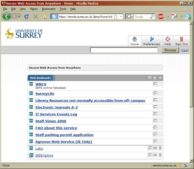
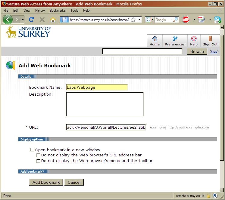
4 Lab Web Page Web Page Online lab manual Videos about experiments Timetables, group lists etc. Experiments not in the lab manual, only on web Software Project Loudspeaker Response Audio-Visual Production Project Acoustic Noise Measurement
5 Remote Access to Web Page Access to some parts only via university IP address Copyright issues with some material Use when off-campus
6
7
8 FM Receiver Project Objective Create a prototype FM receiver Basic design PIC controls FM Receiver Chip LCD Display Programme PIC in C using MPLAB Work in groups of 3-4

9 FM Receiver: System Overview Development Platform Debugger Channel Change Push Buttons Serial Converter Microcontroller PIC18LF6490 Frequency Readout LCD Display Antenna Tuner / Demodulator Audio Amplifier
10 D1: Operational Amplifier Objectives/aims Investigate non-ideal properties of op-amps Bias current, offset voltages, slew rate, etc. Gain vs. frequency plots Integrators Preparation tips Study Clayton book in particular Look at data sheet for 741 op-amp Try some example calculations using data sheet values, particularly for part 1 Sketch out the circuits required Predict the results, sketch some example graphs Briefly describe necessary experiment steps instructions do not say absolutely everything


11 Experiment Part 1 Find offset voltage, bias currents using circuits like this one Too small to measure directly How? Try putting values from the data sheet into equations (a),(b),(c) Are some values much smaller than others?


12 Experiment Part 1 Measure gain and frequency response How do different Rf values change the response? How to use log-linear graph paper? How to find cut-off frequency?
13 J: Transformers Objectives/aims Learn The construction of low frequency transformers The relationship between magnetic flux, induced EMF and magnetising current The idea of a magnetic circuit The limitations of iron as a magnetic material One of the simplest equivalent circuits for the transformer Sources of loss in a transformer and the effect of frequency on the relative magnitude of these losses Preparation tips Basic transformer principles try Wikipedia? Books are usually better Read material in lab manual Answer questions in lab manual Predict results

14 Transformers: Method Goal Design secondary winding to give exactly 6A in the 0.11Ω load resistor, with the primary voltage adjusted to exactly 12V First Analysis of transformer See video for more details
15 Transformers Video
16 K: Wave Propagation Aims/objectives Study standing waves in Coaxial cable Waveguide Free space Learn about standing wave and transmission theory Preparation Read suggested reading material Answer questions in lab manual

17 Part b: Waveguide Standing wave detector Load Gunn Diode Source Cavity Wave Meter Variable Attenuator Crystal Detector* Crystal Detector To CRO To CRO
18 S: Pulse And Wide Bandwidth Measurements Aims/objectives Demonstrate loading and mis-match problems associated with oscilloscope leads and probes Show the effect of parasitic resonances in decoupling circuits. Observe the variation in "ground" potential at different points on a PCB Preparation Answer questions May be able to predict some results based on theory
19 F: Digital Communications Aims/objectives Familiarise you with some of the concepts and problems involved in transmitting digital data from a remote transmitter to a receiver Familiarisation Different pulse shapes, effects of filtering pulse Covers material not in telecoms lectures Preparation Lab manual specifies exercises Equipment manual contains exercise details Available online via web page, also in labs Preparation as specified in lab manual
20 Group Software Design Project: Online publications database Aims/objectives Implement a publications database Record and display summary of university conference and journal publications Work in teams (3-5 people) Learn about MySQL, Perl, CGI Final technical report Preparation Read web page, follow links MySQL reading Look for example publication databases on the web
21 S4: Loudspeaker Frequency Response Objectives/aims Determine the frequency response of a loudspeaker use recordings of the voltage and current, and sound pressure using a measurement microphone Observe the resonant properties of the loudspeaker enclosure, and account for these in the loudspeaker response measurements Preparation Read experiment instructions Can you predict results? How does the Matlab script work?
22 S5: Audio Distortion Measurements Aims/objectives To characterise an audio processing algorithm using various audio distortion measurements To gain familiarity with frequency representations of audio Preparation Read experiment and required reading Study matlab scripts Predict results
23 Summary Experiments likely to start in week 1 Keep checking your , lab web page for updates Printed manual provided in week 1 All material will be placed online during Xmas holidays All labs located in main L2 labs Apart from Media Eng experiments Lab groups should be same as previous semester Check web page for updates
7. Experiment K: Wave Propagation
 7. Experiment K: Wave Propagation This laboratory will be based upon observing standing waves in three different ways, through coaxial cables, in free space and in a waveguide. You will also observe some
ECE3204 D2015 Lab 1. See suggested breadboard configuration on following page!
 ECE3204 D2015 Lab 1 The Operational Amplifier: Inverting and Non-inverting Gain Configurations Gain-Bandwidth Product Relationship Frequency Response Limitation Transfer Function Measurement DC Errors
Practical 2P12 Semiconductor Devices
 Practical 2P12 Semiconductor Devices What you should learn from this practical Science This practical illustrates some points from the lecture courses on Semiconductor Materials and Semiconductor Devices
University of North Carolina, Charlotte Department of Electrical and Computer Engineering ECGR 3157 EE Design II Fall 2009
 University of North Carolina, Charlotte Department of Electrical and Computer Engineering ECGR 3157 EE Design II Fall 2009 Lab 1 Power Amplifier Circuits Issued August 25, 2009 Due: September 11, 2009
UNIVERSITY OF NORTH CAROLINA AT CHARLOTTE Department of Electrical and Computer Engineering
 UNIVERSITY OF NORTH CAROLINA AT CHARLOTTE Department of Electrical and Computer Engineering EXPERIMENT 8 AMPLITUDE MODULATION AND DEMODULATION OBJECTIVES The focus of this lab is to familiarize the student
Experiment 5.A. Basic Wireless Control. ECEN 2270 Electronics Design Laboratory 1
 .A Basic Wireless Control ECEN 2270 Electronics Design Laboratory 1 Procedures 5.A.0 5.A.1 5.A.2 5.A.3 5.A.4 5.A.5 5.A.6 Turn in your pre lab before doing anything else. Receiver design band pass filter
10 GHz Microwave Link
 10 GHz Microwave Link Project Project Objectives System System Functionality Testing Testing Procedures Cautions and Warnings Problems Encountered Recommendations Conclusion PROJECT OBJECTIVES Implement
GCSE Electronics. Scheme of Work
 GCSE Electronics Scheme of Work Week Topic Detail Notes 1 Practical skills assemble a circuit using a diagram recognize a component from its physical appearance (This is a confidence building/motivating
EE12: Laboratory Project (Part-2) AM Transmitter
 AM Transmitter") EE12: Laboratory Project (Part-2) AM Transmitter ECE Department, Tufts University Spring 2008 1 Objective This laboratory exercise is the second part of the EE12 project of building an AM transmitter in
EE12: Laboratory Project (Part-2) AM Transmitter ECE Department, Tufts University Spring 2008 1 Objective This laboratory exercise is the second part of the EE12 project of building an AM transmitter in
ECE 4670 Spring 2014 Lab 1 Linear System Characteristics
 ECE 4670 Spring 2014 Lab 1 Linear System Characteristics 1 Linear System Characteristics The first part of this experiment will serve as an introduction to the use of the spectrum analyzer in making absolute
BME/ISE 3512 Bioelectronics. Laboratory Five - Operational Amplifiers
 BME/ISE 3512 Bioelectronics Laboratory Five - Operational Amplifiers Learning Objectives: Be familiar with the operation of a basic op-amp circuit. Be familiar with the characteristics of both ideal and
EE 3305 Lab I Revised July 18, 2003
 Operational Amplifiers Operational amplifiers are high-gain amplifiers with a similar general description typified by the most famous example, the LM741. The LM741 is used for many amplifier varieties
EE 368 Electronics Lab. Experiment 10 Operational Amplifier Applications (2)
") EE 368 Electronics Lab Experiment 10 Operational Amplifier Applications (2) 1 Experiment 10 Operational Amplifier Applications (2) Objectives To gain experience with Operational Amplifier (Op-Amp). To
EE 368 Electronics Lab Experiment 10 Operational Amplifier Applications (2) 1 Experiment 10 Operational Amplifier Applications (2) Objectives To gain experience with Operational Amplifier (Op-Amp). To
Experiment 8 Frequency Response
 Experiment 8 Frequency Response W.T. Yeung, R.A. Cortina, and R.T. Howe UC Berkeley EE 105 Spring 2005 1.0 Objective This lab will introduce the student to frequency response of circuits. The student will
Week 8 AM Modulation and the AM Receiver
 Week 8 AM Modulation and the AM Receiver The concept of modulation and radio transmission is introduced. An AM receiver is studied and the constructed on the prototyping board. The operation of the AM
describe sound as the transmission of energy via longitudinal pressure waves;
 1 Sound-Detailed Study Study Design 2009 2012 Unit 4 Detailed Study: Sound describe sound as the transmission of energy via longitudinal pressure waves; analyse sound using wavelength, frequency and speed
Laboratory 6. Lab 6. Operational Amplifier Circuits. Required Components: op amp 2 1k resistor 4 10k resistors 1 100k resistor 1 0.
 Laboratory 6 Operational Amplifier Circuits Required Components: 1 741 op amp 2 1k resistor 4 10k resistors 1 100k resistor 1 0.1 F capacitor 6.1 Objectives The operational amplifier is one of the most
DESIGN OF AN ANALOG FIBER OPTIC TRANSMISSION SYSTEM
 DESIGN OF AN ANALOG FIBER OPTIC TRANSMISSION SYSTEM OBJECTIVE To design and build a complete analog fiber optic transmission system, using light emitting diodes and photodiodes. INTRODUCTION A fiber optic
Properties of Inductor and Applications
 LABORATORY Experiment 3 Properties of Inductor and Applications 1. Objectives To investigate the properties of inductor for different types of magnetic material To calculate the resonant frequency of a
MICROWAVE MICROWAVE TRAINING BENCH COMPONENT SPECIFICATIONS:
 Microwave section consists of Basic Microwave Training Bench, Advance Microwave Training Bench and Microwave Communication Training System. Microwave Training System is used to study all the concepts of
EXPERIMENT NUMBER 8 Introduction to Active Filters
 EXPERIMENT NUMBER 8 Introduction to Active Filters i-1 Preface: Preliminary exercises are to be done and submitted individually. Laboratory hardware exercises are to be done in groups. This laboratory
Laboratory 9. Required Components: Objectives. Optional Components: Operational Amplifier Circuits (modified from lab text by Alciatore)
") Laboratory 9 Operational Amplifier Circuits (modified from lab text by Alciatore) Required Components: 1x 741 op-amp 2x 1k resistors 4x 10k resistors 1x l00k resistor 1x 0.1F capacitor Optional Components:
Laboratory 9 Operational Amplifier Circuits (modified from lab text by Alciatore) Required Components: 1x 741 op-amp 2x 1k resistors 4x 10k resistors 1x l00k resistor 1x 0.1F capacitor Optional Components:
Application Note 5525
 Using the Wafer Scale Packaged Detector in 2 to 6 GHz Applications Application Note 5525 Introduction The is a broadband directional coupler with integrated temperature compensated detector designed for
Homework Assignment 03
 Question (75 points) Homework Assignment 03 Overview Tuned Radio Frequency (TRF) receivers are some of the simplest type of radio receivers. They consist of a parallel RLC bandpass filter with bandwidth
Electronics Design Laboratory Lecture #1, Fall 2014
 Electronics Design Laboratory Lecture #1, Fall 2014 Dr. Daniel Seltzer Teaching Assistants: Fenglong Lu & Ali Sepahvand Electronics Design Laboratory 1 Daniel Seltzer seltzer@colorado.edu Fenglong Lu Fenglong.Lu@colorado.edu
EE2210 Laboratory Project 1 Fall 2013 Function Generator and Oscilloscope
 EE2210 Laboratory Project 1 Fall 2013 Function Generator and Oscilloscope For students to become more familiar with oscilloscopes and function generators. Pre laboratory Work Read the TDS 210 Oscilloscope
Mechatronics. Analog and Digital Electronics: Studio Exercises 1 & 2
 Mechatronics Analog and Digital Electronics: Studio Exercises 1 & 2 There is an electronics revolution taking place in the industrialized world. Electronics pervades all activities. Perhaps the most important
FREQUENCY RESPONSE AND PASSIVE FILTERS LABORATORY
 FREQUENCY RESPONSE AND PASSIVE FILTERS LABORATORY In this experiment we will analytically determine and measure the frequency response of networks containing resistors, AC source/sources, and energy storage
Matrix Multimedia Limited Tel Fax
 matrix multimedia Electronic Circuits and Components v2.0 Course material with Virtual Laboratories that stimulate, teach & test. This second version of Electronic Circuits and Components is bigger and
Optical Infrared Communications
 10/22/2010 Optical Infrared Communications.doc 1/17 Optical Infrared Communications Once information has been glued onto a carrier signal the information is used to modulate the carrier signal in some
Intro To Engineering II for ECE: Lab 7 The Op Amp Erin Webster and Dr. Jay Weitzen, c 2014 All rights reserved.
 Lab 7: The Op Amp Laboratory Objectives: 1) To introduce the operational amplifier or Op Amp 2) To learn the non-inverting mode 3) To learn the inverting mode 4) To learn the differential mode Before You
UNIVERSITY OF NORTH CAROLINA AT CHARLOTTE Department of Electrical and Computer Engineering
 UNIVERSITY OF NORTH CAROLINA AT CHARLOTTE Department of Electrical and Computer Engineering EXPERIMENT 5 GAIN-BANDWIDTH PRODUCT AND SLEW RATE OBJECTIVES In this experiment the student will explore two
XRT6164A Digital Line Interface Transceiver
 Digital Line Interface Transceiver October 2007 FEATURES Single 5V Supply Compatible with CCITT G.703 64Kbps Co- Directional Interface Recommendation When Used With Either XRT6165 or XRT6166 Low Power
EE301 ELECTRONIC CIRCUITS CHAPTER 2 : OSCILLATORS. Lecturer : Engr. Muhammad Muizz Bin Mohd Nawawi
 EE301 ELECTRONIC CIRCUITS CHAPTER 2 : OSCILLATORS Lecturer : Engr. Muhammad Muizz Bin Mohd Nawawi 2.1 INTRODUCTION An electronic circuit which is designed to generate a periodic waveform continuously at
Transmit filter designs for ADSL modems
 EE 233 Laboratory-4 1. Objectives Transmit filter designs for ADSL modems Design a filter from a given topology and specifications. Analyze the characteristics of the designed filter. Use SPICE to verify
Lecture Week 4. Homework Voltage Divider Equivalent Circuit Observation Exercise
 Lecture Week 4 Homework Voltage Divider Equivalent Circuit Observation Exercise Homework: P6 Prove that the equation relating change in potential energy to voltage is dimensionally consistent, using the
UNIT 2. Q.1) Describe the functioning of standard signal generator. Ans. Electronic Measurements & Instrumentation
 Describe the functioning of standard signal generator. Ans. Electronic Measurements & Instrumentation") UNIT 2 Q.1) Describe the functioning of standard signal generator Ans. STANDARD SIGNAL GENERATOR A standard signal generator produces known and controllable voltages. It is used as power source for the
UNIT 2 Q.1) Describe the functioning of standard signal generator Ans. STANDARD SIGNAL GENERATOR A standard signal generator produces known and controllable voltages. It is used as power source for the
Noise by the Numbers
 Noise by the Numbers 1 What can I do with noise? The two primary applications for white noise are signal jamming/impairment and reference level comparison. Signal jamming/impairment is further divided
KULLIYYAH OF ENGINEERING
 KULLIYYAH OF ENGINEERING DEPARTMENT OF ELECTRICAL & COMPUTER ENGINEERING ANTENNA AND WAVE PROPAGATION LABORATORY (ECE 4103) EXPERIMENT NO 3 RADIATION PATTERN AND GAIN CHARACTERISTICS OF THE DISH (PARABOLIC)
Class #9: Experiment Diodes Part II: LEDs
 Class #9: Experiment Diodes Part II: LEDs Purpose: The objective of this experiment is to become familiar with the properties and uses of LEDs, particularly as a communication device. This is a continuation
BME 3512 Bioelectronics Laboratory Five - Operational Amplifiers
 BME 351 Bioelectronics Laboratory Five - Operational Amplifiers Learning Objectives: Be familiar with the operation of a basic op-amp circuit. Be familiar with the characteristics of both ideal and real
OPERATIONAL AMPLIFIERS (OP-AMPS) II
 II") OPERATIONAL AMPLIFIERS (OP-AMPS) II LAB 5 INTRO: INTRODUCTION TO INVERTING AMPLIFIERS AND OTHER OP-AMP CIRCUITS GOALS In this lab, you will characterize the gain and frequency dependence of inverting op-amp
OPERATIONAL AMPLIFIERS (OP-AMPS) II LAB 5 INTRO: INTRODUCTION TO INVERTING AMPLIFIERS AND OTHER OP-AMP CIRCUITS GOALS In this lab, you will characterize the gain and frequency dependence of inverting op-amp
Radio Frequency Power Meter Design Project
 Radio Frequency Power Meter Design Project Timothy Holt and Andrew Milks University of Akron, Akron Ohio Abstract This student paper discusses a radio frequency power meter developed and prototyped as
The Principle V(SWR) The Result. Mirror, Mirror, Darkly, Darkly
 The Result. Mirror, Mirror, Darkly, Darkly") The Principle V(SWR) The Result Mirror, Mirror, Darkly, Darkly 1 Question time!! What do you think VSWR (SWR) mean to you? What does one mean by a transmission line? Coaxial line Waveguide Water pipe Tunnel
The Principle V(SWR) The Result Mirror, Mirror, Darkly, Darkly 1 Question time!! What do you think VSWR (SWR) mean to you? What does one mean by a transmission line? Coaxial line Waveguide Water pipe Tunnel
Lab E2: B-field of a Solenoid. In the case that the B-field is uniform and perpendicular to the area, (1) reduces to
 reduces to") E2.1 Lab E2: B-field of a Solenoid In this lab, we will explore the magnetic field created by a solenoid. First, we must review some basic electromagnetic theory. The magnetic flux over some area A is
E2.1 Lab E2: B-field of a Solenoid In this lab, we will explore the magnetic field created by a solenoid. First, we must review some basic electromagnetic theory. The magnetic flux over some area A is
ITT Technical Institute. ET275 Electronic Communications Systems I Onsite Course SYLLABUS
 ITT Technical Institute ET275 Electronic Communications Systems I Onsite Course SYLLABUS Credit hours: 4 Contact/Instructional hours: 50 (30 Theory Hours, 20 Lab Hours) Prerequisite(s) and/or Corequisite(s):
Rf Circuit Design Theory And Applications 2nd Edition Download
 Rf Circuit Design Theory And Applications 2nd Edition Download We have made it easy for you to find a PDF Ebooks without any digging. And by having access to our ebooks online or by storing it on your
University of Pittsburgh
 University of Pittsburgh Experiment #7 Lab Report Analog-Digital Applications Submission Date: 08/01/2018 Instructors: Dr. Ahmed Dallal Shangqian Gao Submitted By: Nick Haver & Alex Williams Station #2
Filters And Waveform Shaping
 Physics 3330 Experiment #3 Fall 2001 Purpose Filters And Waveform Shaping The aim of this experiment is to study the frequency filtering properties of passive (R, C, and L) circuits for sine waves, and
EE 421L Digital Electronics Laboratory. Laboratory Exercise #9 ADC and DAC
 EE 421L Digital Electronics Laboratory Laboratory Exercise #9 ADC and DAC Department of Electrical and Computer Engineering University of Nevada, at Las Vegas Objective: The purpose of this laboratory
4. Digital Measurement of Electrical Quantities
 4.1. Concept of Digital Systems Concept A digital system is a combination of devices designed for manipulating physical quantities or information represented in digital from, i.e. they can take only discrete
When you have completed this exercise, you will be able to relate the gain and bandwidth of an op amp
 Op Amp Fundamentals When you have completed this exercise, you will be able to relate the gain and bandwidth of an op amp In general, the parameters are interactive. However, in this unit, circuit input
Laboratory Project 4: Frequency Response and Filters
 2240 Laboratory Project 4: Frequency Response and Filters K. Durney and N. E. Cotter Electrical and Computer Engineering Department University of Utah Salt Lake City, UT 84112 Abstract-You will build a
ENEE 307 Electronic Circuit Design Laboratory Spring 2012
 ENEE 307 Electronic Circuit Design Laboratory Spring 2012 Agis A. Iliadis Electrical Engineering Department University of Maryland College Park MD 20742 Wireless Communications-Transmitters 4.1. Wireless
6.101 Introductory Analog Electronics Laboratory
 6.101 Introductory Analog Electronics Laboratory Spring 2015, Instructor Gim Hom Project Proposal Transmitting, Receiving, and Interpreting ECG Waveforms Daniel Moon (dhmoon@mit.edu) Thipok (Ben) Rak-amnouykit
Kent Bertilsson Muhammad Amir Yousaf
 Today s topics Analog System (Rev) Frequency Domain Signals in Frequency domain Frequency analysis of signals and systems Transfer Function Basic elements: R, C, L Filters RC Filters jw method (Complex
Practical Testing Techniques For Modern Control Loops
 VENABLE TECHNICAL PAPER # 16 Practical Testing Techniques For Modern Control Loops Abstract: New power supply designs are becoming harder to measure for gain margin and phase margin. This measurement is
University of North Carolina-Charlotte Department of Electrical and Computer Engineering ECGR 3157 Electrical Engineering Design II Fall 2013
 Exercise 1: PWM Modulator University of North Carolina-Charlotte Department of Electrical and Computer Engineering ECGR 3157 Electrical Engineering Design II Fall 2013 Lab 3: Power-System Components and
Exercise 1: RF Stage, Mixer, and IF Filter
 SSB Reception Analog Communications Exercise 1: RF Stage, Mixer, and IF Filter EXERCISE OBJECTIVE DISCUSSION On the circuit board, you will set up the SSB transmitter to transmit a 1000 khz SSB signal
Rowan University Freshman Clinic I Lab Project 2 The Operational Amplifier (Op Amp)
") Rowan University Freshman Clinic I Lab Project 2 The Operational Amplifier (Op Amp) Objectives Become familiar with an Operational Amplifier (Op Amp) electronic device and it operation Learn several basic
Rowan University Freshman Clinic I Lab Project 2 The Operational Amplifier (Op Amp) Objectives Become familiar with an Operational Amplifier (Op Amp) electronic device and it operation Learn several basic
PHYS 536 The Golden Rules of Op Amps. Characteristics of an Ideal Op Amp
 PHYS 536 The Golden Rules of Op Amps Introduction The purpose of this experiment is to illustrate the golden rules of negative feedback for a variety of circuits. These concepts permit you to create and
Transformer Waveforms
 OBJECTIVE EXPERIMENT Transformer Waveforms Steady-State Testing and Performance of Single-Phase Transformers Waveforms The voltage regulation and efficiency of a distribution system are affected by the
Oct 10 & 17 EGR 220: Engineering Circuit Theory Due Oct 17 & 24 Lab 4: Op Amp Circuits
 Oct 10 & 17 EGR 220: Engineering Circuit Theory Due Oct 17 & 24 Lab 4: Op Amp Circuits Objective The objective of this lab is to build simple op amp circuits and compare observed behavior with theoretical
EE 233 Circuit Theory Lab 2: Amplifiers
 EE 233 Circuit Theory Lab 2: Amplifiers Table of Contents 1 Introduction... 1 2 Precautions... 1 3 Prelab Exercises... 2 3.1 LM348N Op-amp Parameters... 2 3.2 Voltage Follower Circuit Analysis... 2 3.2.1
Practical 2P12 Semiconductor Devices
 Practical 2P12 Semiconductor Devices What you should learn from this practical Science This practical illustrates some points from the lecture courses on Semiconductor Materials and Semiconductor Devices
Chapter 8: Field Effect Transistors
 Chapter 8: Field Effect Transistors Transistors are different from the basic electronic elements in that they have three terminals. Consequently, we need more parameters to describe their behavior than
Test No. 2. Advanced Scope Measurements. History. University of Applied Sciences Hamburg. Last chance!! EEL2 No 2
 University of Applied Sciences Hamburg Group No : DEPARTMENT OF INFORMATION ENGINEERING Laboratory for Instrumentation and Measurement L1: in charge of the report Test No. 2 Date: Assistant A2: Professor:
PowerAmp Design. PowerAmp Design PAD541 COMPACT POWER OP AMP
 PowerAmp Design COMPACT POWER OP AMP Rev E KEY FEATURES LOW COST HIGH VOLTAGE 00 VOLTS HIGH OUTPUT CURRENT 5 AMPS 50 WATT DISSIPATION CAPABILITY 00 WATT OUTPUT CAPABILITY 0.63 HEIGHT SIP DESIGN APPLICATIONS
Microwave Circuit Design and Measurements Lab. INTRODUCTION TO MICROWAVE MEASUREMENTS: DETECTION OF RF POWER AND STANDING WAVES Lab #2
 EE 458/558 Microwave Circuit Design and Measurements Lab INTRODUCTION TO MICROWAVE MEASUREMENTS: DETECTION OF RF POWER AND STANDING WAVES Lab #2 The purpose of this lab is to gain a basic understanding
LFR: flexible, clip-around current probe for use in power measurements
 LFR: flexible, clip-around current probe for use in power measurements These technical notes should be read in conjunction with the LFR short-form datasheet. Power Electronic Measurements Ltd Nottingham
ET275P Electronic Communications Systems I [Onsite]
![ET275P Electronic Communications Systems I [Onsite]](/thumbs/85/92760903.jpg "ET275P Electronic Communications Systems I [Onsite]") ET275P Electronic Communications Systems I [Onsite] Course Description: In this course, several methods of signal transmission and reception are covered, including such techniques as mixing, modulating
ET275P Electronic Communications Systems I [Onsite] Course Description: In this course, several methods of signal transmission and reception are covered, including such techniques as mixing, modulating
UNIT-1: CIRCUIT CONCEPT. capacitor. the market to purchase a resistor, apart from resistance what else will you quote so that the safety is ensured?
 UNIT-1: CIRCUIT CONCEPT * 1) Explain in brief about Lumped circuit elements called resistor and capacitor. ** 2) Write a short note on Ammeter and Voltmeter. ** 3) How does a voltmeter differ from an ammeter?
Michael Hermansen. Low-Noise Piezoelectric Driver for External Cavity Diode Lasers. Physics 492R Capstone. 10 April Advisor: Dr.
 1 Michael Hermansen Low-Noise Piezoelectric Driver for External Cavity Diode Lasers Physics 492R Capstone 10 April 2012 Advisor: Dr. Dallin Durfee 2 1. Abstract: I built a piezoelectric amplifier for a
Laboratory Project 1a: Power-Indicator LED's
 2240 Laboratory Project 1a: Power-Indicator LED's Abstract-You will construct and test two LED power-indicator circuits for your breadboard in preparation for building the Electromyogram circuit in Lab
ECEN Network Analysis Section 3. Laboratory Manual
 ECEN 3714----Network Analysis Section 3 Laboratory Manual LAB 07: Active Low Pass Filter Oklahoma State University School of Electrical and Computer Engineering. Section 3 Laboratory manual - 1 - Spring
Design and Implementation of Digital Stethoscope using TFT Module and Matlab Visualisation Tool
 World Journal of Technology, Engineering and Research, Volume 3, Issue 1 (2018) 297-304 Contents available at WJTER World Journal of Technology, Engineering and Research Journal Homepage: www.wjter.com
Lab #5 Steady State Power Analysis
 Lab #5 Steady State Power Analysis Steady state power analysis refers to the power analysis of circuits that have one or more sinusoid stimuli. This lab covers the concepts of RMS voltage, maximum power
CHARACTERIZATION OF OP-AMP
 EXPERIMENT 4 CHARACTERIZATION OF OP-AMP OBJECTIVES 1. To sketch and briefly explain an operational amplifier circuit symbol and identify all terminals. 2. To list the amplifier stages in a typical op-amp
ELEC3242 Communications Engineering Laboratory Amplitude Modulation (AM)
") ELEC3242 Communications Engineering Laboratory 1 ---- Amplitude Modulation (AM) 1. Objectives 1.1 Through this the laboratory experiment, you will investigate demodulation of an amplitude modulated (AM)
ELEC3242 Communications Engineering Laboratory 1 ---- Amplitude Modulation (AM) 1. Objectives 1.1 Through this the laboratory experiment, you will investigate demodulation of an amplitude modulated (AM)
MAHARASHTRA STATE BOARD OF TECHNICAL EDUCATION (Autonomous) (ISO/IEC Certified) SUMMER 14 EXAMINATION Model Answer
 (ISO/IEC Certified) SUMMER 14 EXAMINATION Model Answer") MAHARASHTRA STATE BOARD OF TECHNICAL EDUCATION (Autonomous) (ISO/IEC 27001 2005 Certified) SUMMER 14 EXAMINATION Model Answer Subject Code : 17317 Page No: 1 Important Instructions to examiners: 1) The
MAHARASHTRA STATE BOARD OF TECHNICAL EDUCATION (Autonomous) (ISO/IEC 27001 2005 Certified) SUMMER 14 EXAMINATION Model Answer Subject Code : 17317 Page No: 1 Important Instructions to examiners: 1) The
EC 554 Data Communications
 EC 554 Data Communications Mohamed Khedr http://webmail. webmail.aast.edu/~khedraast.edu/~khedr Syllabus Tentatively Week 1 Week 2 Week 3 Week 4 Week 5 Week 6 Week 7 Week 8 Week 9 Week 10 Week 11 Week
Dev Bhoomi Institute Of Technology Department of Electronics and Communication Engineering PRACTICAL INSTRUCTION SHEET REV. NO. : REV.
 Dev Bhoomi Institute Of Technology Department of Electronics and Communication Engineering PRACTICAL INSTRUCTION SHEET LABORATORY MANUAL EXPERIMENT NO. ISSUE NO. : ISSUE DATE: July 200 REV. NO. : REV.
Homework Assignment 06
 Question 1 (2 points each unless noted otherwise) Homework Assignment 06 1. True or false: when transforming a circuit s diagram to a diagram of its small-signal model, we replace dc constant current sources
DATA CONVERSION AND LAB (17.368) Fall Class # 07. October 16, 2008
 Fall Class # 07. October 16, 2008") DATA CONVERSION AND LAB (17.368) Fall 2008 Class # 07 October 16, 2008 Dohn Bowden 1 Today s Lecture Outline Course Admin Lab #3 next week Exam in two weeks 10/30/08 Detailed Technical Discussions Digital
DATA CONVERSION AND LAB (17.368) Fall 2008 Class # 07 October 16, 2008 Dohn Bowden 1 Today s Lecture Outline Course Admin Lab #3 next week Exam in two weeks 10/30/08 Detailed Technical Discussions Digital
Putting it all Together
 ECE 2C Laboratory Manual 5b Putting it all Together.continuation of Lab 5a In-Lab Procedure At this stage you should have your transmitter circuit hardwired on a vectorboard, and your receiver circuit
Analog RF Electronics Education at SDSMT: A Hands-On Method for Teaching Electrical Engineers
 Analog RF Electronics Education at : A Hands-On Method for Teaching Electrical Engineers Dr., Professor Department of Electrical and Computer Engineering South Dakota School of Mines and Technology (whites@sdsmt.edu)
EE 210: CIRCUITS AND DEVICES
 EE 210: CIRCUITS AND DEVICES OPERATIONAL AMPLIFIERS PART II This is the second of two laboratory sessions that provide an introduction to the op amp. In this session you will study three amplifiers designs:
Intruder Alarm Name Mohamed Alsubaie MMU ID Supervisor Pr. Nicholas Bowring Subject Electronic Engineering Unit code 64ET3516
 Intruder Alarm Name MMU ID Supervisor Subject Unit code Course Mohamed Alsubaie 09562211 Pr. Nicholas Bowring Electronic Engineering 64ET3516 BEng (Hons) Computer and Communication Engineering 1. Introduction
GOVERNMENT OF KARNATAKA KARNATAKA STATE PRE-UNIVERSITY EDUCATION EXAMINATION BOARD II YEAR PUC EXAMINATION MARCH-2012 SCHEME OF VALUATION
 GOVERNMENT OF KARNATAKA KARNATAKA STATE PRE-UNIVERSITY EDUCATION EXAMINATION BOARD II YEAR PUC EXAMINATION MARCH-0 SCHEME OF VALUATION Subject Code: 0 Subject: Qn. PART - A 0. Which is the largest of three
Radar Shield System Design
 University of California, Davis EEC 193 Final Project Report Radar Shield System Design Lit Po Kwong: lkwong853@gmail.com Yuyang Xie: szyuyxie@gmail.com Ivan Lee: yukchunglee@hotmail.com Ri Liang: joeliang914@gmail.com
MASSACHUSETTS INSTITUTE OF TECHNOLOGY Hands-On Introduction to EE Lab Skills Laboratory No. 2 BJT, Op Amps IAP 2008
 Name MASSACHUSETTS INSTITUTE OF TECHNOLOGY 6.09 Hands-On Introduction to EE Lab Skills Laboratory No. BJT, Op Amps IAP 008 Objective In this laboratory, you will become familiar with a simple bipolar junction
ELEC3106 Electronics. Lab 3: PCB EMI measurements. Objective. Components. Set-up
 ELEC3106 Electronics Lab 3: PCB EMI measurements Objective The objective of this laboratory session is to give the students a good understanding of critical PCB level Electromagnetic Interference phenomena
Linear electronic. Lecture No. 1
 1 Lecture No. 1 2 3 4 5 Lecture No. 2 6 7 8 9 10 11 Lecture No. 3 12 13 14 Lecture No. 4 Example: find Frequency response analysis for the circuit shown in figure below. Where R S =4kR B1 =8kR B2 =4k R
The Discussion of this exercise covers the following points:
 Exercise 3-2 Frequency-Modulated CW Radar EXERCISE OBJECTIVE When you have completed this exercise, you will be familiar with FM ranging using frequency-modulated continuous-wave (FM-CW) radar. DISCUSSION
Department of Electronic Engineering NED University of Engineering & Technology. LABORATORY WORKBOOK For the Course SIGNALS & SYSTEMS (TC-202)
") Department of Electronic Engineering NED University of Engineering & Technology LABORATORY WORKBOOK For the Course SIGNALS & SYSTEMS (TC-202) Instructor Name: Student Name: Roll Number: Semester: Batch:
Department of Electronic Engineering NED University of Engineering & Technology LABORATORY WORKBOOK For the Course SIGNALS & SYSTEMS (TC-202) Instructor Name: Student Name: Roll Number: Semester: Batch:
INFLUENCE OF THE PERFOMANCE PARAMETERS IN TRANSMISSION LINE LOUDSPEAKER SYSTEM
 INFLUENCE OF THE PERFOMANCE PARAMETERS IN TRANSMISSION LINE LOUDSPEAKER SYSTEM PACS number: 43.38.Ja Basilio Pueo, José Escolano, and Miguel Romá Department of Physics, System Engineering and Signal Theory,
THIRD SEMESTER ELECTRONICS - II BASIC ELECTRICAL & ELECTRONICS LAB DEPARTMENT OF ELECTRICAL ENGINEERING
 THIRD SEMESTER ELECTRONICS - II BASIC ELECTRICAL & ELECTRONICS LAB DEPARTMENT OF ELECTRICAL ENGINEERING Prepared By: Checked By: Approved By: Engr. Saqib Riaz Engr. M.Nasim Khan Dr.Noman Jafri Lecturer
ECE 5670/6670 Project. Brushless DC Motor Control with 6-Step Commutation. Objectives
 ECE 5670/6670 Project Brushless DC Motor Control with 6-Step Commutation Objectives The objective of the project is to build a circuit for 6-step commutation of a brushless DC motor and to implement control
Testing Motorola DMR MOTOTRBO Radios with the Cobham 3920B Radio Test Platform
 Application Note Testing Motorola DMR MOTOTRBO Radios with the Cobham 3920B Radio Test Platform The Cobham 3920B is the complete tool for anyone wishing to test Analog or Digital MOTOTRBO mobile or portable
Volunteer Audio. Glossary
 Volunteer Audio Glossary A Aftermarket Designates audio components produced by manufacturers other than the OEMs designed to replace and/or upgrade those installed in a vehicle when it was first placed