ATC Air Traffic Control - Catalogue 13
|
|
|
- Sara Stevenson
- 5 years ago
- Views:
Transcription
1

2


3
4 ATC Air Traffic Control - Catalogue 1 Via Senatore Simonetta,2 287 Caponago (MB) - Italy tel.: fax info@sira.mi.it
5
 Italy.")


6 history SIRA SIRA is a privately owned company, founded in 1977 by a group of technicians active in the telecommunication field and specialized in RF technology. Sira has 11, sq.meters of manufacturing and support facility based in Caponago (MI) Italy. SIRA is a customer oriented company, which has adopted the philosophy of working together with its customers to meet the critical technical requirements for their systems with an attitude of enthusiasm and concern in order to provide the best results in the final products. This approach has given Sira a position of leadership in its field. Sira products are designed and manufactured in accordance with the particular international standards in force in the area. As a major position of its cross revenues, Sira has been investing in research and development, quality and reliability control and products safety in the RF field. This policy of investments has provided Sira with an extremely high level of experience in its field: there are Sira installations in more than 8 countries in the world. 1
 and is certified according to the norms UNI EN ISO 91 (2) and UNI EN 141 (199).")


7 quality SIRA s aim is to give to all its customers reliable products and services with the highest quality standards, this ambitious goal is achieved mainly by means of an integrated management system (Quality-Safety-environment) and is certified according to the norms UNI EN ISO 91 (2) and UNI EN 141 (199). The enhancement of company efficiency through the continuous improvement of the operative quality of the internal functions (effectiveness), the reduction of defects on sold products and the notable attention to the quality culture at all company levels have become SIRA s fundamental cares. Moreover SIRA is committed in a thorough policy of environmental protection: a training and information process on all personnel is continuously carried out in order to grant a responsible management of all the activities in a special respect of the environment. For instance, the development and the implementation of new technologies, products and production processes is carried out with a thorough control for a rational use of energetic sources and of raw materials, minimizing the production of waste and the use of non-renewable resources, everything with the aim of keeping environmental impact on air and water as lowest as it is possible. For all SIRA s activities it is fundamental to oppose the conditions of life and work which are against the health of the workers, as well as promoting freedom principles and self-respect for any human being. An extract from SIRA s ethic code states that Sira refuses any discrimination based on sex, race, languages, personal and social conditions, religion and political choices and to this aim Sira promotes a working environment that, inspired to the principles of respect, fairness and collaboration, is meant to support the involvement of all Employees and Contributors giving the common sense of responsibility in reaching all the Company goals. 2
8 index VHF and UHF broadband omnidirectional antenna Vertical Polarization 5 Multi dipole UHF omnidirectional antenna Vertical Polarization 11 Multi dipole VHF omnidirectional antenna Vertical Polarization 2 Multi dipole VHF/UHF omnidirectional antenna Vertical Polarization 29 Anti-Icing System 7
9
10 VHF and UHF broadband omnidirectional antenna Vertical Polarization TBT 2-/V 7 TBT 2-/U 9 VHF and UHF broadband omnidirectional antenna Vertical Polarization TYPE NO. TYPE # INPUTS ANT/TBT 2-/U ANT/TBT 2-/V VPol Omni VPol Omni MHz MHz 2 dbi 2 dbi 1xNf 1xNf HEIGHT 94 mm 192 mm 5
11
12 TBT 2-/V GROUND TO AIR COMMUNICATION OMNIDIRECTIONAL ANTENNA FEATURES vertical polarization broadband MHz 2 dbi gain omnidirectional pattern ELECTRICAL DATA TYPE FREQUENCY RANGE IMPEDANCE CONNECTOR MAX POWER VSWR POLARIZATION GAIN HALF POWER BEAMWIDTH LIGHTNING PROTECTION TBT 2-/V MHz 5 ohm NF 5 W ( MHz) Vertical 2 dbi E-plane 75 H-plane (omni ±. db) All metal parts of the antenna, including the mounting kit and the inner conductor, are DC grounded RADIATION PATTERNS (Mid Band) 27 9 MECHANICAL DATA DIMENSIONS WEIGHT (braket excluded) WIND SURFACE WIND LOAD (wind speed 15 km/h) MAX. WIND VELOCITY ICING PROTECTION RADOME COLOUR MOUNTING PACKING 192 x ø 82 mm 7 kg.11 m 2 12 N 24 km/h Full radome Grey (std.), other on request On pole 157 x 19 x 19 mm 1 18 H-plane E-plane DS /4 Specifications are subject to change without prior notice 7
13 ADDITIONAL INFORMATION Mounting: The antenna can be attached laterally at the tip of a tubular mast of -12 mm diameter with two brackets supplied with the antenna (connecting cable runs outside the mast). Materials: Radiator: Aluminium. Radome: Fiberglass, colour: Grey. Base: Weather-proof aluminium. Mounting kit, screws and nuts: Stainless steel. PLEASE NOTE: As a result of more stringent legal regulations and judgements regarding product liability, we are obliged to point out certain risks that may arise when products are used under extraordinary operating conditions. The mechanical design is based on the environmental conditions as stipulated in ETS , which include the static mechanical load imposed on an antenna by wind at maximum velocity. Extraordinary operating conditions, such as heavy icing or exceptional dynamic stress (e.g. strain caused by oscillating support structures), may result in the breakage of an antenna or even cause it to fall to the ground. These facts must be considered during the site planning process. The installation team must be properly qualified and also be familiar with the relevant national safety regulations. The details given in our data sheets have to be followed carefully when installing the antennas and accessories. The limits for the coupling torque of RF-connectors, recommended by the connector manufactures must be obeyed. DS /4 Specifications are subject to change without prior notice 8
14 TBT 2-/U GROUND TO AIR COMMUNICATION OMNIDIRECTIONAL ANTENNA FEATURES vertical polarization broadband MHz 2 dbi gain omnidirectional pattern ELECTRICAL DATA TYPE FREQUENCY RANGE IMPEDANCE CONNECTOR MAX POWER VSWR POLARIZATION GAIN HALF POWER BEAMWIDTH LIGHTNING PROTECTION TBT 2-/U MHz 5 ohm NF W 2. Vertical 2 dbi E-plane 75 H-plane (omni ±.5 db) All metal parts of the antenna, including the mounting kit and the inner conductor, are DC grounded RADIATION PATTERNS (Mid Band) 27 9 MECHANICAL DATA DIMENSIONS WEIGHT (braket excluded) WIND SURFACE WIND LOAD (wind speed 15 km/h) MAX. WIND VELOCITY ICING PROTECTION RADOME COLOUR MOUNTING PACKING 94 x ø 82 mm kg.8 m 2 85 N 24 km/h Full radome Grey (std.), other on request On pole 1125 x 19 x 19 mm 1 18 H-plane E-plane DS / Specifications are subject to change without prior notice 9
15 ADDITIONAL INFORMATION Mounting: The antenna can be attached laterally at the tip of a tubular mast of -12 mm diameter with two brackets supplied with the antenna (connecting cable runs outside the mast). Materials: Radiator: Aluminium. Radome: Fiberglass, colour: Grey. Base: Weather-proof aluminium. Mounting kit, screws and nuts: Stainless steel. PLEASE NOTE: As a result of more stringent legal regulations and judgements regarding product liability, we are obliged to point out certain risks that may arise when products are used under extraordinary operating conditions. The mechanical design is based on the environmental conditions as stipulated in ETS , which include the static mechanical load imposed on an antenna by wind at maximum velocity. Extraordinary operating conditions, such as heavy icing or exceptional dynamic stress (e.g. strain caused by oscillating support structures), may result in the breakage of an antenna or even cause it to fall to the ground. These facts must be considered during the site planning process. The installation team must be properly qualified and also be familiar with the relevant national safety regulations. The details given in our data sheets have to be followed carefully when installing the antennas and accessories. The limits for the coupling torque of RF-connectors, recommended by the connector manufactures must be obeyed. DS / Specifications are subject to change without prior notice 1
16 Multi dipole UHF omnidirectional antenna Vertical Polarization TBT 2-/U2 1 TBT 2-/U 15 TBT 2-/U4 17 TBT 2-/U5 19 TBT 2-/U 21 Multi dipole UHF omnidirectional antenna Vertical Polarization TYPE NO. ANT/TBT 2-/U2 ANT/TBT 2-/U ANT/TBT 2-/U4 ANT/TBT 2-/U5 ANT/TBT 2-/U TYPE # INPUTS HEIGHT VPol Omni VPol Omni MHz MHz 2 dbi 2 dbi 2xNf xnf 29 mm 7 mm VPol Omni MHz 2 dbi 4xNf 4785 mm VPol Omni MHz 2 dbi 5xNf 581 mm VPol Omni MHz 2 dbi xnf 85 mm 11
17
18 TBT 2-/U2 GROUND TO AIR COMMUNICATION OMNIDIRECTIONAL ANTENNA FEATURES vertical polarization broadband MHz 2 dbi gain omnidirectional multi-element antenna consisting of two indipendently fed UHF dipoles ELECTRICAL DATA TYPE FREQUENCY RANGE IMPEDANCE CONNECTOR MAX POWER VSWR POLARIZATION GAIN HALF POWER BEAMWIDTH DECOUPLING LIGHTNING PROTECTION TBT 2-/U MHz 5 ohm NF 4 W 2. Vertical 2 dbi E-plane 75 H-plane >27 db The metal parts of the antenna, including the mounting kit and the inner conductors are DC grounded RADIATION PATTERNS (Mid Band) 27 9 MECHANICAL DATA DIMENSIONS WEIGHT WIND SURFACE WIND LOAD (wind speed 15 km/h) MAX. WIND VELOCITY ICING PROTECTION RADOME COLOUR MOUNTING 29 x ø 19 mm 4.5 kg.45 m 2 45 N 24 km/h Full radome Grey (std.), other on request On a flanged supporting pipe Flange 29 mm diameter 1 18 H-plane E-plane DS /1 Specifications are subject to change without prior notice 1
19 ADDITIONAL INFORMATION Mounting: The antenna can be attached on the top of a flanged supporting pipe. Materials: Radiator: Aluminium, brass. Radome: Fiberglass, colour: grey. Base: Hot dip galvanized steel. All screws and nuts: Stainless steel. Two eyebolts for an easy lifting of the antenna PLEASE NOTE: As a result of more stringent legal regulations and judgements regarding product liability, we are obliged to point out certain risks that may arise when products are used under extraordinary operating conditions. The mechanical design is based on the environmental conditions as stipulated in ETS , which include the static mechanical load imposed on an antenna by wind at maximum velocity. Extraordinary operating conditions, such as heavy icing or exceptional dynamic stress (e.g. strain caused by oscillating support structures), may result in the breakage of an antenna or even cause it to fall to the ground. These facts must be considered during the site planning process. The installation team must be properly qualified and also be familiar with the relevant national safety regulations. The details given in our data sheets have to be followed carefully when installing the antennas and accessories. The limits for the coupling torque of RF-connectors, recommended by the connector manufactures must be obeyed. DS /1 Specifications are subject to change without prior notice 14
20 TBT 2-/U GROUND TO AIR COMMUNICATION OMNIDIRECTIONAL ANTENNA FEATURES vertical polarization broadband MHz 2 dbi gain omnidirectional multi-element antenna consisting of three indipendently fed UHF dipoles ELECTRICAL DATA TYPE FREQUENCY RANGE IMPEDANCE CONNECTOR MAX POWER VSWR POLARIZATION GAIN HALF POWER BEAMWIDTH DECOUPLING (between adjacent dipoles) LIGHTNING PROTECTION TBT 2-/U MHz 5 ohm NF 4 W 2. Vertical 2 dbi E-plane 75 H-plane >27 db The metal parts of the antenna, including the mounting kit and the inner conductors are DC grounded RADIATION PATTERNS (Mid Band) 27 9 MECHANICAL DATA DIMENSIONS WEIGHT WIND SURFACE WIND LOAD (wind speed 15 km/h) MAX. WIND VELOCITY ICING PROTECTION RADOME COLOUR MOUNTING 7 x ø 19 mm 9 kg. m N 24 km/h Full radome Grey (std.), other on request On a flanged supporting pipe Flange 29 mm diameter 1 18 H-plane E-plane DS /1 Specifications are subject to change without prior notice 15
21 ADDITIONAL INFORMATION Mounting: The antenna can be attached on the top of a flanged supporting pipe. Materials: Radiator: Aluminium, brass. Radome: Fiberglass, colour: grey. Base: Hot dip galvanized steel. All screws and nuts: Stainless steel. Two eyebolts for an easy lifting of the antenna PLEASE NOTE: As a result of more stringent legal regulations and judgements regarding product liability, we are obliged to point out certain risks that may arise when products are used under extraordinary operating conditions. The mechanical design is based on the environmental conditions as stipulated in ETS , which include the static mechanical load imposed on an antenna by wind at maximum velocity. Extraordinary operating conditions, such as heavy icing or exceptional dynamic stress (e.g. strain caused by oscillating support structures), may result in the breakage of an antenna or even cause it to fall to the ground. These facts must be considered during the site planning process. The installation team must be properly qualified and also be familiar with the relevant national safety regulations. The details given in our data sheets have to be followed carefully when installing the antennas and accessories. The limits for the coupling torque of RF-connectors, recommended by the connector manufactures must be obeyed. DS /1 Specifications are subject to change without prior notice 1
22 TBT 2-/U4 GROUND TO AIR COMMUNICATION OMNIDIRECTIONAL ANTENNA FEATURES vertical polarization broadband MHz 2 dbi gain omnidirectional multi-element antenna consisting of four indipendently fed UHF dipoles ELECTRICAL DATA TYPE FREQUENCY RANGE IMPEDANCE CONNECTOR MAX POWER VSWR POLARIZATION GAIN HALF POWER BEAMWIDTH DECOUPLING (between adjacent dipoles) LIGHTNING PROTECTION TBT 2-/U MHz 5 ohm NF 4 W 2. Vertical 2 dbi E-plane 75 H-plane >27 db The metal parts of the antenna, including the mounting kit and the inner conductors are DC grounded RADIATION PATTERNS (Mid Band) 27 9 MECHANICAL DATA DIMENSIONS WEIGHT WIND SURFACE WIND LOAD (wind speed 15 km/h) MAX. WIND VELOCITY ICING PROTECTION RADOME COLOUR MOUNTING 477 x ø 19 mm 44 kg.81 m 2 1 N 24 km/h Full radome Grey (std.), other on request On a flanged supporting pipe Flange 29 mm diameter 1 18 H-plane E-plane DS /1 Specifications are subject to change without prior notice 17
23 ADDITIONAL INFORMATION Mounting: The antenna can be attached on the top of a flanged supporting pipe. Materials: Radiator: Aluminium, brass. Radome: Fiberglass, colour: grey. Base: Hot dip galvanized steel. All screws and nuts: Stainless steel. Two eyebolts for an easy lifting of the antenna PLEASE NOTE: As a result of more stringent legal regulations and judgements regarding product liability, we are obliged to point out certain risks that may arise when products are used under extraordinary operating conditions. The mechanical design is based on the environmental conditions as stipulated in ETS , which include the static mechanical load imposed on an antenna by wind at maximum velocity. Extraordinary operating conditions, such as heavy icing or exceptional dynamic stress (e.g. strain caused by oscillating support structures), may result in the breakage of an antenna or even cause it to fall to the ground. These facts must be considered during the site planning process. The installation team must be properly qualified and also be familiar with the relevant national safety regulations. The details given in our data sheets have to be followed carefully when installing the antennas and accessories. The limits for the coupling torque of RF-connectors, recommended by the connector manufactures must be obeyed. DS /1 Specifications are subject to change without prior notice 18
24 TBT 2-/U5 GROUND TO AIR COMMUNICATION OMNIDIRECTIONAL ANTENNA FEATURES vertical polarization broadband MHz 2 dbi gain omnidirectional multi-element antenna consisting of five indipendently fed UHF dipoles ELECTRICAL DATA TYPE FREQUENCY RANGE IMPEDANCE CONNECTOR MAX POWER VSWR POLARIZATION GAIN HALF POWER BEAMWIDTH DECOUPLING (between adjacent dipoles) LIGHTNING PROTECTION TBT 2-/U MHz 5 ohm NF 4 W 2. Vertical 2 dbi E-plane 75 H-plane >27 db The metal parts of the antenna, including the mounting kit and the inner conductors are DC grounded RADIATION PATTERNS (Mid Band) 27 9 MECHANICAL DATA DIMENSIONS WEIGHT WIND SURFACE WIND LOAD (wind speed 15 km/h) MAX. WIND VELOCITY ICING PROTECTION RADOME COLOUR MOUNTING 581 x ø 19 mm 48.5 kg.98 m 2 74 N 24 km/h Full radome Grey (std.), other on request On a flanged supporting pipe Flange 29 mm diameter 1 18 H-plane E-plane Specifications are subject to change without prior notice 19
25 ADDITIONAL INFORMATION Mounting: The antenna can be attached on the top of a flanged supporting pipe. Materials: Radiator: Aluminium, brass. Radome: Fiberglass, colour: grey. Base: Hot dip galvanized steel. All screws and nuts: Stainless steel. Two eyebolts for an easy lifting of the antenna PLEASE NOTE: As a result of more stringent legal regulations and judgements regarding product liability, we are obliged to point out certain risks that may arise when products are used under extraordinary operating conditions. The mechanical design is based on the environmental conditions as stipulated in ETS , which include the static mechanical load imposed on an antenna by wind at maximum velocity. Extraordinary operating conditions, such as heavy icing or exceptional dynamic stress (e.g. strain caused by oscillating support structures), may result in the breakage of an antenna or even cause it to fall to the ground. These facts must be considered during the site planning process. The installation team must be properly qualified and also be familiar with the relevant national safety regulations. The details given in our data sheets have to be followed carefully when installing the antennas and accessories. The limits for the coupling torque of RF-connectors, recommended by the connector manufactures must be obeyed Specifications are subject to change without prior notice 2
26 TBT 2-/U GROUND TO AIR COMMUNICATION OMNIDIRECTIONAL ANTENNA FEATURES vertical polarization broadband MHz 2 dbi gain omnidirectional multi-element antenna consisting of six indipendently fed UHF dipoles ELECTRICAL DATA TYPE FREQUENCY RANGE IMPEDANCE CONNECTOR MAX POWER VSWR POLARIZATION GAIN HALF POWER BEAMWIDTH DECOUPLING (between adjacent dipoles) LIGHTNING PROTECTION TBT 2-/U MHz 5 ohm NF 4 W 2. Vertical 2 dbi E-plane 75 H-plane >27 db The metal parts of the antenna, including the mounting kit and the inner conductors are DC grounded RADIATION PATTERNS (Mid Band) 27 9 MECHANICAL DATA DIMENSIONS WEIGHT WIND SURFACE WIND LOAD (wind speed 15 km/h) MAX. WIND VELOCITY ICING PROTECTION RADOME COLOUR MOUNTING 85 x ø 19 mm 5.5 kg 1.1 m N 24 km/h Full radome Grey (std.), other on request On a flanged supporting pipe Flange 29 mm diameter 1 18 H-plane E-plane DS /1 Specifications are subject to change without prior notice 21
27 ADDITIONAL INFORMATION Mounting: The antenna can be attached on the top of a flanged supporting pipe. Materials: Radiator: Aluminium, brass. Radome: Fiberglass, colour: grey. Base: Hot dip galvanized steel. All screws and nuts: Stainless steel. Two eyebolts for an easy lifting of the antenna PLEASE NOTE: As a result of more stringent legal regulations and judgements regarding product liability, we are obliged to point out certain risks that may arise when products are used under extraordinary operating conditions. The mechanical design is based on the environmental conditions as stipulated in ETS , which include the static mechanical load imposed on an antenna by wind at maximum velocity. Extraordinary operating conditions, such as heavy icing or exceptional dynamic stress (e.g. strain caused by oscillating support structures), may result in the breakage of an antenna or even cause it to fall to the ground. These facts must be considered during the site planning process. The installation team must be properly qualified and also be familiar with the relevant national safety regulations. The details given in our data sheets have to be followed carefully when installing the antennas and accessories. The limits for the coupling torque of RF-connectors, recommended by the connector manufactures must be obeyed. DS /1 Specifications are subject to change without prior notice 22
28 Multi dipole VHF omnidirectional antenna Vertical Polarization TBT 2-/V2 25 TBT 2-/V 27 Multi dipole VHF omnidirectional antenna Vertical Polarization TYPE NO. TYPE ANT/TBT 2-/V2 ANT/TBT 2-/V VPol Omni VPol Omni MHz MHz 2 dbi 2 dbi # INPUTS 2xNf xnf HEIGHT 4785 mm 725 mm 2
29
30 TBT 2-/V2 GROUND TO AIR COMMUNICATION OMNIDIRECTIONAL ANTENNA FEATURES vertical polarization broadband MHz 2 dbi gain omnidirectional multi-element antenna consisting of two indipendently fed VHF dipoles ELECTRICAL DATA TYPE FREQUENCY RANGE IMPEDANCE CONNECTOR MAX POWER VSWR POLARIZATION GAIN HALF POWER BEAMWIDTH DECOUPLING LIGHTNING PROTECTION TBT 2-/V MHz 5 ohm NF 5 W 2. Vertical 2 dbi E-plane 75 H-plane >2 db (typical >25 db) The metal parts of the antenna, including the mounting kit and the inner conductors are DC grounded RADIATION PATTERNS (Mid Band) 27 9 MECHANICAL DATA DIMENSIONS WEIGHT WIND SURFACE WIND LOAD (wind speed 15 km/h) MAX. WIND VELOCITY ICING PROTECTION RADOME COLOUR MOUNTING 4785 x ø 19 mm 45.5 kg.81 m 2 1 N 24 km/h Full radome Grey (std.), other on request On a flanged supporting pipe Flange 29 mm diameter 1 18 H-plane E-plane DS /1 Specifications are subject to change without prior notice 25
31 ADDITIONAL INFORMATION Mounting: The antenna can be attached on the top of a flanged supporting pipe. Materials: Radiator: Aluminium, brass. Radome: Fiberglass, colour: grey. Base: Hot dip galvanized steel. All screws and nuts: Stainless steel. Two eyebolts for an easy lifting of the antenna PLEASE NOTE: As a result of more stringent legal regulations and judgements regarding product liability, we are obliged to point out certain risks that may arise when products are used under extraordinary operating conditions. The mechanical design is based on the environmental conditions as stipulated in ETS , which include the static mechanical load imposed on an antenna by wind at maximum velocity. Extraordinary operating conditions, such as heavy icing or exceptional dynamic stress (e.g. strain caused by oscillating support structures), may result in the breakage of an antenna or even cause it to fall to the ground. These facts must be considered during the site planning process. The installation team must be properly qualified and also be familiar with the relevant national safety regulations. The details given in our data sheets have to be followed carefully when installing the antennas and accessories. The limits for the coupling torque of RF-connectors, recommended by the connector manufactures must be obeyed. DS /1 Specifications are subject to change without prior notice 2
32 TBT 2-/V GROUND TO AIR COMMUNICATION OMNIDIRECTIONAL ANTENNA FEATURES vertical polarization broadband MHz 2 dbi gain omnidirectional multi-element antenna consisting of three indipendently fed VHF dipoles ELECTRICAL DATA TYPE FREQUENCY RANGE IMPEDANCE CONNECTOR MAX POWER VSWR POLARIZATION GAIN HALF POWER BEAMWIDTH DECOUPLING LIGHTNING PROTECTION TBT 2-/V MHz 5 ohm NF 5 W 2. Vertical 2 dbi E-plane 75 H-plane >2 db (typical >25 db) The metal parts of the antenna, including the mounting kit and the inner conductors are DC grounded RADIATION PATTERNS (Mid Band) 27 9 MECHANICAL DATA DIMENSIONS WEIGHT WIND SURFACE WIND LOAD (wind speed 15 km/h) MAX. WIND VELOCITY ICING PROTECTION RADOME COLOUR MOUNTING 725 x ø 19 mm 57.5 kg 1.19 m N 24 km/h Full radome Grey (std.), other on request On a flanged supporting pipe Flange 29 mm diameter 1 18 H-plane E-plane DS /1 Specifications are subject to change without prior notice 27
33 ADDITIONAL INFORMATION Mounting: The antenna can be attached on the top of a flanged supporting pipe. Materials: Radiator: Aluminium, brass. Radome: Fiberglass, colour: grey. Base: Hot dip galvanized steel. All screws and nuts: Stainless steel. Two eyebolts for an easy lifting of the antenna PLEASE NOTE: As a result of more stringent legal regulations and judgements regarding product liability, we are obliged to point out certain risks that may arise when products are used under extraordinary operating conditions. The mechanical design is based on the environmental conditions as stipulated in ETS , which include the static mechanical load imposed on an antenna by wind at maximum velocity. Extraordinary operating conditions, such as heavy icing or exceptional dynamic stress (e.g. strain caused by oscillating support structures), may result in the breakage of an antenna or even cause it to fall to the ground. These facts must be considered during the site planning process. The installation team must be properly qualified and also be familiar with the relevant national safety regulations. The details given in our data sheets have to be followed carefully when installing the antennas and accessories. The limits for the coupling torque of RF-connectors, recommended by the connector manufactures must be obeyed. DS /1 Specifications are subject to change without prior notice 28
34 Multi dipole VHF/UHF omnidirectional antenna Vertical Polarization TBT 2-/UV 1 TBT 2-/UVU TBT 2-/VUV 5 Multi dipole VHF/UHF omnidirectional antenna Vertical Polarization TYPE NO. ANT/TBT 2-/UV VPol Omni TYPE / MHz 2 dbi # INPUTS 2xNf HEIGHT 5 mm ANT/TBT 2-/UVU VPol Omni / / MHz 2 dbi xnf 4785 mm ANT/TBT 2-/VUV VPol Omni / / MHz 2 dbi xnf 725 mm 29
35
36 TBT 2-/UV GROUND TO AIR COMMUNICATION OMNIDIRECTIONAL ANTENNA FEATURES vertical polarization broadband and MHz 2 dbi gain omnidirectional multi-element antenna consisting of one VHF and one UHF dipole (indipendently fed) ELECTRICAL DATA TYPE FREQUENCY RANGE IMPEDANCE CONNECTOR MAX POWER VSWR POLARIZATION GAIN HALF POWER BEAMWIDTH DECOUPLING LIGHTNING PROTECTION TBT 2-/UV VHF: MHz UHF: MHz 5 ohm NF 5 W 4 W 2. Vertical 2 dbi E-plane 75 H-plane at UHF >2 db (typical >25 db) at VHF >2 db (typical >25 db) The metal parts of the antenna, including the mounting kit and the inner conductors are DC grounded RADIATION PATTERNS (Mid Band) 27 9 MECHANICAL DATA DIMENSIONS WEIGHT WIND SURFACE WIND LOAD (wind speed 15 km/h) MAX. WIND VELOCITY ICING PROTECTION RADOME COLOUR MOUNTING 5 x ø 19 mm 8.5 kg.2 m 2 45 N 24 km/h Full radome Grey (std.), other on request On a flanged supporting pipe Flange 29 mm diameter 1 18 H-plane E-plane DS /1 Specifications are subject to change without prior notice 1
37 ADDITIONAL INFORMATION Mounting: The antenna can be attached on the top of a flanged supporting pipe. Materials: Radiator: Aluminium, brass. Radome: Fiberglass, colour: grey. Base: Hot dip galvanized steel. All screws and nuts: Stainless steel. Two eyebolts for an easy lifting of the antenna PLEASE NOTE: As a result of more stringent legal regulations and judgements regarding product liability, we are obliged to point out certain risks that may arise when products are used under extraordinary operating conditions. The mechanical design is based on the environmental conditions as stipulated in ETS , which include the static mechanical load imposed on an antenna by wind at maximum velocity. Extraordinary operating conditions, such as heavy icing or exceptional dynamic stress (e.g. strain caused by oscillating support structures), may result in the breakage of an antenna or even cause it to fall to the ground. These facts must be considered during the site planning process. The installation team must be properly qualified and also be familiar with the relevant national safety regulations. The details given in our data sheets have to be followed carefully when installing the antennas and accessories. The limits for the coupling torque of RF-connectors, recommended by the connector manufactures must be obeyed. DS /1 Specifications are subject to change without prior notice 2
38 TBT 2-/UVU GROUND TO AIR COMMUNICATION OMNIDIRECTIONAL ANTENNA FEATURES vertical polarization broadband and MHz 2 dbi gain omnidirectional multi-element antenna consisting of one VHF and two UHF dipoles (indipendently fed) ELECTRICAL DATA TYPE FREQUENCY RANGE IMPEDANCE CONNECTOR MAX POWER VSWR POLARIZATION GAIN HALF POWER BEAMWIDTH DECOUPLING LIGHTNING PROTECTION TBT 2-/UVU VHF: MHz UHF: MHz 5 ohm NF 5 W 4 W 2. Vertical 2 dbi E-plane 75 H-plane UHF - UHF >25 db UHF - VHF at UHF >24 db (typical >25 db) UHF - VHF at VHF >22 db (typical >25 db) The metal parts of the antenna, including the mounting kit and the inner conductors are DC grounded RADIATION PATTERNS (Mid Band) 27 9 MECHANICAL DATA DIMENSIONS WEIGHT WIND SURFACE WIND LOAD (wind speed 15 km/h) MAX. WIND VELOCITY ICING PROTECTION RADOME COLOUR MOUNTING 49 x ø 19 mm 4.5 kg.79 m 2 N 24 km/h Full radome Grey (std.), other on request On a flanged supporting pipe Flange 29 mm diameter 1 18 H-plane E-plane DS /1 Specifications are subject to change without prior notice
39 ADDITIONAL INFORMATION Mounting: The antenna can be attached on the top of a flanged supporting pipe. Materials: Radiator: Aluminium, brass. Radome: Fiberglass, colour: grey. Base: Hot dip galvanized steel. All screws and nuts: Stainless steel. Two eyebolts for an easy lifting of the antenna PLEASE NOTE: As a result of more stringent legal regulations and judgements regarding product liability, we are obliged to point out certain risks that may arise when products are used under extraordinary operating conditions. The mechanical design is based on the environmental conditions as stipulated in ETS , which include the static mechanical load imposed on an antenna by wind at maximum velocity. Extraordinary operating conditions, such as heavy icing or exceptional dynamic stress (e.g. strain caused by oscillating support structures), may result in the breakage of an antenna or even cause it to fall to the ground. These facts must be considered during the site planning process. The installation team must be properly qualified and also be familiar with the relevant national safety regulations. The details given in our data sheets have to be followed carefully when installing the antennas and accessories. The limits for the coupling torque of RF-connectors, recommended by the connector manufactures must be obeyed. DS /1 Specifications are subject to change without prior notice 4
40 TBT 2-/VUV GROUND TO AIR COMMUNICATION OMNIDIRECTIONAL ANTENNA FEATURES vertical polarization broadband and MHz 2 dbi gain omnidirectional multi-element antenna consisting of one UHF and two VHF dipoles (indipendently fed) ELECTRICAL DATA TYPE FREQUENCY RANGE IMPEDANCE CONNECTOR MAX POWER VSWR POLARIZATION GAIN HALF POWER BEAMWIDTH DECOUPLING LIGHTNING PROTECTION TBT 2-/VUV VHF: MHz UHF: MHz 5 ohm NF 5 W 4 W 2. Vertical 2 dbi E-plane 75 H-plane VHF - VHF >22 db (typical >25 db) VHF - UHF at VHF >25 db VHF - UHF at UHF >22 db (typical >25 db) The metal parts of the antenna, including the mounting kit and the inner conductors are DC grounded RADIATION PATTERNS (Mid Band) 27 9 MECHANICAL DATA DIMENSIONS (mm) WEIGHT (kg) WIND SURFACE (m 2 ) WIND LOAD (wind speed 15 km/h) (N) MAX. WIND VELOCITY ICING PROTECTION RADOME COLOUR MOUNTING x ø 19 mm km/h Full radome Grey (std.), other on request On a flanged supporting pipe Flange 29 mm diameter 1 18 H-plane E-plane DS /1 Specifications are subject to change without prior notice 5
41 ADDITIONAL INFORMATION Mounting: The antenna can be attached on the top of a flanged supporting pipe. Materials: Radiator: Aluminium, brass. Radome: Fiberglass, colour: grey. Base: Hot dip galvanized steel. All screws and nuts: Stainless steel. Two eyebolts for an easy lifting of the antenna PLEASE NOTE: As a result of more stringent legal regulations and judgements regarding product liability, we are obliged to point out certain risks that may arise when products are used under extraordinary operating conditions. The mechanical design is based on the environmental conditions as stipulated in ETS , which include the static mechanical load imposed on an antenna by wind at maximum velocity. Extraordinary operating conditions, such as heavy icing or exceptional dynamic stress (e.g. strain caused by oscillating support structures), may result in the breakage of an antenna or even cause it to fall to the ground. These facts must be considered during the site planning process. The installation team must be properly qualified and also be familiar with the relevant national safety regulations. The details given in our data sheets have to be followed carefully when installing the antennas and accessories. The limits for the coupling torque of RF-connectors, recommended by the connector manufactures must be obeyed. DS /1 Specifications are subject to change without prior notice


42 Anti-Icing System 7


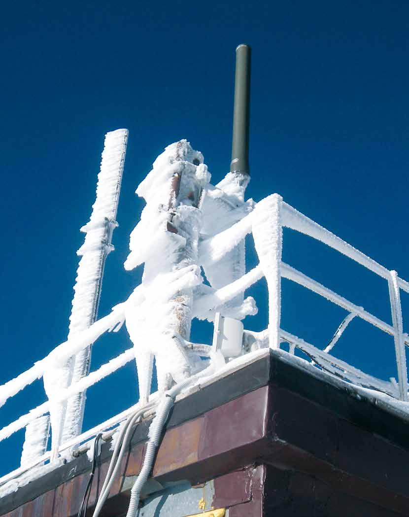
43 ANTI-ICING SYSTEM SIRA has developed an anti-icing system to be connected to the base flange of the multi coaxial dipole VHF/UHF antennas. This anti-icing system allows the control of the hot air flow inside the antenna radome. MAIN FEATURES OF THE SIRA SOLUTION: Redundancy of system s components Reduction of energy consumption The ANTI-ICING system modulates heating power in accordance to the external environmental conditions. The system is designed only using passive components inside the antenna (no maintenance). Distribution of the heating over the entire length of the antenna. CAlling Air-Intake Hot air The activation of the remote control can be made through RS22 or TCP-IP. Anti-Icing kit ON HEATING RADOME 8


44 ANTI-ICING SYSTEM Schematic block - Master and Slave Multi coaxial dipole VHF/UHF antennas 1 2 N RESISTANCE FAN SLAVE > PLUG AND PLAY Master POWER SUPPLY REMOTE CONTROL The system is based on a programmable Logic controller (PLC) that receives data from a professional weather station on temperature and frost conditions. Professional Weather Station with calibration certificate. 9


45 ANTI- ICING SYSTEM Trial Terminillo site mountain 2 m Multi coaxial dipole antennas UVU Height = 4.7 mt Professional Weather Station Anti-Icing system Remote control 4
46
MHz Base Station Antennas for Mobile Communications
 27 512 MHz Base Station Antennas for Mobile Communications Photo on title page: Applications for TETRA. Catalogue Issue /4 All data published in previous catalog issues hereby becomes invalid. We reserve
MHz Base Station Antennas for Mobile Communications
 27 512 27 512 MHz Base Station Antennas for Mobile Communications Photo on title page: Applications for TETRA. Catalogue Issue 2/27 All data published in previous catalog issues hereby becomes invalid.
4-Port Antenna Frequency Range Dual Polarization HPBW Adjust. Electr. DT
 4-Port Antenna Frequency Range Dual Polarization HPB Adjust. Electr. DT R1 790 960 0.5 9.5 0 6 set by hand or by optional RCU (Remote Control Unit) X 65 B1 1710 2180 X 65 4-Port Antenna 790 960/1710 2180
6-Port Antenna Frequency Range Dual Polarization HPBW Adjust. Electr. DT set by hand or by optional RCU (Remote Control Unit)
") 6-Port Antenna Frequency Range Dual Polarization HPBW Adjust. Electr. DT R1 698 960 1710 2690 1710 2690 1.5 10 0 10 2 10 set by hand or by optional RCU (Remote Control Unit) X Y1 X Y2 65 65 65 X 6-Port
6-Port Antenna Frequency Range Dual Polarization HPBW Adjust. Electr. DT R1 698 960 1710 2690 1710 2690 1.5 10 0 10 2 10 set by hand or by optional RCU (Remote Control Unit) X Y1 X Y2 65 65 65 X 6-Port
4-Port Antenna Frequency Range Dual Polarization HPBW Adjust. Electr. DT
 4-Port Antenna Frequency Range Dual Polarization HPB Adjust. Electr. DT R1 790 960 0 10 2 8 set by hand or by optional RCU (Remote Control Unit) X 65 Y1 1710 2690 X 65 4-Port Antenna 790 960/1710 2690
6-Port Antenna Frequency Range Dual Polarization HPBW Adjust. Electr. DT
 6-Port Antenna Frequency Range Dual Polarization HPBW Adjust. Electr. DT R1 1710 1880 0 10 0 6 0 6 set by hand or by optional RCU (Remote Control Unit) B1 B2 1920 2170 6-Port Antenna /1710 1880/1920 2170
4-Port Antenna ircu / /65 16/18.5dBi 0 10 /0 10 T V01
 4-Port Antenna Frequency Range Dual Polarization Half-power Beam Width Integrated replaceable Remote Control Unit Adjustable Electrical Downtilt 0 10 0 10 4-Port Antenna 698 894/1710 2170 65 /65 16/18.5dBi
Accessories Stand-off Brackets
 ccessories Stand-off Brackets The omni antennas radiate horizontally in a circular fashion. However, they can also be mounted laterally to a mast by using an extension bracket. Depending on the spacing
MHz KATHREIN-Antennas and Antenna Line Products. For Public Safety, Ports, Airports, Distribution, Public Transport, Utilities
 27 512 MHz KATHREIN-Antennas and Antenna Line Products For Public Safety, Ports, Airports, Distribution, Public Transport, Utilities Photo on title page: Applications for TETRA. Catalogue Issue 1/211 All
2-Port Antenna Frequency Range Dual Polarization HPBW Adjust. Electr. DT Enhanced Sidelobe Suppression
 2-Port Antenna Frequency Range Dual Polarization HPBW Adjust. Electr. DT Enhanced Sidelobe Suppression 1710 2690 18 Downtilt set by hand or by optional RCU (Remote Control Unit) X 65 2 14 2-Port Antenna
clamps included Single Unit Double Unit
 Designed for co-siting purposes Enables feeder sharing Can be used as a combiner near the BTS or in a reciprocal function near the antenna Suitable for indoor or outdoor applications Wall or mast mounting
DTMA-1800-UMTS-12-AISG
 DTMA--UMTS-12- Double units for easy use with XXPol antennas Suitable for antenna RET control according to /3GPP standard Bypass mode to ensure cell operation in case of power down Supports 1.1 and 2.0
Omnidirectional Antenna Vertical Polarization Indoor and outdoor use
 db Omnidirectional Antenna and outdoor use 17 27 Omni 17 27 6 2dBi 8 41 N female Connector position Bottom or top 17 27 MHz SWR < 1.8 2 dbi Intermodulation IM < 15 dbc (2 x 4 dbm carrier) ertical 5 W (at
8-Port Antenna Frequency Range Dual Polarization HPBW Adjust. Electr. DT set by hand or by optional RCU (Remote Control Unit)
") Frequency Range Dual Polarization HPB Adjust. Electr. DT R1 790 960 790 960 X 1710 2180 1710 2180 0 10 0 10 0 6 0 6 set by hand or by optional RCU (Remote Control Unit) X 65 65 R2 B1 B2 X X 60 60 8-Port
Frequency Range Dual Polarization HPB Adjust. Electr. DT R1 790 960 790 960 X 1710 2180 1710 2180 0 10 0 10 0 6 0 6 set by hand or by optional RCU (Remote Control Unit) X 65 65 R2 B1 B2 X X 60 60 8-Port
DTMA AISG. Fullband Double Dual Duplex Tower Mounted Amplifier (Masthead Amplifier)
") Compact line Double units for easy use with XPol antennas Supports AISG 1.1 and AISG 2.0 (default) Suitable for antenna RET control according to AISG/3GPP standard By-pass mode to ensure cell operation
Compact line Double units for easy use with XPol antennas Supports AISG 1.1 and AISG 2.0 (default) Suitable for antenna RET control according to AISG/3GPP standard By-pass mode to ensure cell operation
4-Port Antenna Frequency Range Dual Polarization HPBW Adjust. Electr. DT
 Frequency Range Dual Polarization HPB Adjust. Electr. DT R1 698 960 Y1 1710 2690 1.5 10 2 8 set by hand or by optional RCU (Remote Control Unit) X 65 X 65 4-Port Antenna 698 960/1710 2690 65 /65 17/18.5dBi
The coupling torque at 7-16 connectors is Nm! The tightning torque for fi xing the AISG connector must be Nm!
 Attention: The coupling torque at 7-16 connectors is 25-30 Nm! The tightning torque for fi xing the AISG connector must be 0.5-1 Nm! 936.2179a Änderungen vorbehalten Internet: http://www.kathrein.de Page
8-Port Antenna Frequency Range Dual Polarization HPBW Adjust. Electr. DT
 Frequency Range Dual Polarization HPB Adjust. Electr. DT R1 790 960 B1 1710 1880 B2 1920 2170 Y1 2490 2690 X X X X 65 65 65 65 0.5 9.5 2 8 2 8 2 8 set by hand or by optional RCU (Remote Control Unit) 8-Port
4-Port Antenna Frequency Range Dual Polarization HPBW Adjust. Electr. DT Enhanced Sidelobe Suppression
 Frequency Range Dual Polarization HPB Adjust. Electr. DT Enhanced Sidelobe Suppression Y1 18dB 18dB Downtilt set by hand or by optional RCU (Remote Control Unit) X 65 2 14 X 65 2 14 4-Port Antenna / 65
4-Port Antenna Frequency Range Dual Polarization HPBW Adjust. Electr. DT
 Frequency Range Dual Polarization HPB Adjust. Electr. DT R1 790 960 B1 1710 2180 0 14 0 8 set by hand or by optional RCU (Remote Control Unit) X 65 X 65 4-Port Antenna 790 960/1710 2180 65 /65 14.5/17.5dBi
6-Port Antenna Frequency Range Dual Polarization HPBW Adjust. Electr. DT set by
 6-Port Antenna Frequency Range Dual Polarization HPBW Adjust. Electr. DT set by R1 Y1 Y2 698 960 1710 2690 1710 2690 X X X 65 65 65 1 10 2.5 12 2.5 12 6-Port Antenna 698 960/1710 2690/1710 2690 65 /65
6-Port Antenna Frequency Range Dual Polarization HPBW Adjust. Electr. DT set by hand or by optional RCU (Remote Control Unit)
") Frequency Range Dual Polarization HPB Adjust. Electr. DT 698 960 1710 2690 1710 2690 1.5 10 0 10 2 10 set by hand or by optional RCU (Remote Control Unit) X X 65 65 65 X 6-Port Antenna 698 960/1710 2690/1710
Frequency Range Dual Polarization HPB Adjust. Electr. DT 698 960 1710 2690 1710 2690 1.5 10 0 10 2 10 set by hand or by optional RCU (Remote Control Unit) X X 65 65 65 X 6-Port Antenna 698 960/1710 2690/1710
6-Port Antenna Frequency Range Dual Polarization HPBW Adjust. Electr. DT set by hand or by optional RCU (Remote Control Unit)
") Frequency Range Dual Polarization HPB Adjust. Electr. DT 698 960 1710 2690 1710 2690 1 12 2 12 2 12 set by hand or by optional RCU (Remote Control Unit) X X 65 65 65 X 6-Port Antenna 698 960/1710 2690/1710
Frequency Range Dual Polarization HPB Adjust. Electr. DT 698 960 1710 2690 1710 2690 1 12 2 12 2 12 set by hand or by optional RCU (Remote Control Unit) X X 65 65 65 X 6-Port Antenna 698 960/1710 2690/1710
4-Port Antenna Frequency Range Dual Polarization HPBW Adjust. Electr. DT set by
 4-Port Antenna Frequency Range Dual Polarization HPB Adjust. Electr. DT set by R1 698 960 X 65 2 12 R2 698 960 X 65 2 12 4-Port Antenna 698 960/698 960 65 /65 15.5/15.5dBi 2 12 /2 12 T Type No. 80010901
4-Port Antenna Frequency Range Dual Polarization HPBW Adjust. Electr. DT
 4-Port Antenna Frequency Range Dual Polarization HPB Adjust. Electr. DT Y1 Y2 3300 3800 3300 3800 2 12 set by hand or by optional RCU (Remote Control Unit) X X 65 65 4-Port Antenna 3300 3800/3300 3800
12-Port Antenna Frequency Range Dual Polarization HPBW Adjust. Electr. DT set by
 12-Port Antenna Frequency Range Dual Polarization HPB Adjust. Electr. DT set by R1 R2 Y1 Y2 Y3 Y4 698 803 824 894 1695 2690 1695 2690 1695 2690 1695 2690 X X X X X X 65 65 65 65 65 65 1.5 10 1.5 10 2.5
12-Port Antenna Frequency Range Dual Polarization HPBW Adjust. Electr. DT set by
 12-Port Antenna Frequency Range Dual Polarization HPB Adjust. Electr. DT set by R1 R2 Y1 Y2 Y3 Y4 698 803 824 894 1695 2690 1695 2690 1695 2690 1695 2690 X X X X X X 65 65 65 65 65 65 2 12 2 12 2 14 2
4-Port Antenna Frequency Range Dual Polarization HPBW Adjust. Electr. DT
 4-Port Antenna Frequency Range Dual Polarization HPBW Adjust. Electr. DT R1 0.5 7 0 6 set by hand or by optional RCU (Remote Control Unit) X 90 B1 X 90 4-Port Antenna / 90 /90 16.5/18i 0.5 7 /0 6 T Type
Product Catalogue. WiMAX & Wireless Antennas. permission of All Max Electronics Ltd. Specifications subject to change without prior notice.
 Ver. 2.4 Ver. 2.4 REVISED MARCH 2014 All Max Electronics Ltd. Product Catalogue WiMAX & Wireless Antennas Revision: 2.4 This document is the exclusive property of All Max Electronics Ltd. and should not
Special Communication
 CATALOGUE 2018/2 Special Counication Antennas and Solutions for Blue Light and Armed Forces SPECIAL COMMUNICATION Who we are and what we stand for Kathrein is a specialist for reliable, high-quality counication
700 MHz MiMO Yagi Antenna
 Seriously Smart Radios for Linking Critical Communications Infrastructure 700 MHz MiMO Yagi Antenna The 700 MHz MiMO Yagi Antenna with Dual Polarization is a high gain, premium quality antenna with excellent
6-Port Antenna Frequency Range Dual Polarization HPBW Adjust. Electr. DT set by hand or by optional RCU (Remote Control Unit)
") 6-Port Antenna Frequency Range Dual Polarization HPBW Adjust. Electr. DT R1 790 960 1710 2180 1710 2180 2 14 0 14 0 14 set by hand or by optional RCU (Remote Control Unit) X B1 X B2 65 65 65 X 6-Port Antenna
6-Port Antenna Frequency Range Dual Polarization HPBW Adjust. Electr. DT R1 790 960 1710 2180 1710 2180 2 14 0 14 0 14 set by hand or by optional RCU (Remote Control Unit) X B1 X B2 65 65 65 X 6-Port Antenna
Wideband Quasi-Omni Antenna
 DATA SHEET Two foot (0.5 m), two port, quasi-omni antenna with uniform horizontal beamwidths covering the extended band from 1710-2690 MHz 360 of coverage area across all bands of operation in a single
BCA. Combiners and Filters for FM Broadcast and TV Systems
 BCA Combiners and Filters for FM Broadcast and TV Systems Photo on title page: FM Multipattern Combiner, 3x 10 kw Catalogue Issue 03/2007 All data published in previous catalog issues hereby becomes invalid.
FM FILTERS AND COMBINERS - CATALOGUE 14
 SIRA ANYWHERE THE SOLUTION FM Filters and Combiners Catalogue 14 FM Filters and Combiners Via Senatore Simonetta,26-20867 Caponago (MB) - Italy phone +39.02.95.961.1 - fax +39.02.95.961.311 E-mail info@sira.mi.it
Microwave Antennas making the world smaller
 Microwave Antennas making the world smaller www.procom.dk Index MICROWAVE ANTENNAS 10 GHz Omnidirectional Antennas WGSL 10 2 Parabolic Antennas PRO-10-001/25 3 PRO-10-001/50 4 Accessories PRO-10-... 5
P300/P350 Series. Vertically Polarized FM Antenna. Features. Characteristics
 Vertically Polarized FM Features Low VSWR, superior VSWR band width, minimal weather related VSWR problems Fully pressurized, internal feed, welded feed connections, series fed radiating elements High
AIR BAND ANTENNAS SUMMARY
 SUMMARY Collinear 85 140 MHz, any 5% Coaxial Dipoles 118 136 MHz, any 3% Sidemount Dipoles 118 136 MHz Stack Dipole Arrays 118 136 MHz Monocones 118 136 MHz Discones 70 1000 MHz G12 Air Band Collinear
SpecifIcations DCF 500 DCF 2000 DCF 5000 TCF 3000
 FM Double & Triple Cavity Filters DCF 500 DCF 2000 DCF 5000 TCF 3000 These high quality Cavity Filters are one-quarter wavelength coaxial cavities designed for the 87,5 108 MHz band. They are band pass
HyperLink Wireless 2.4/ 5 GHz Dual Band / Dual Polarized Omni Antenna Model: HG DPU
 HyperLink Wireless 2.4/ 5 GHz Dual Band / Dual Polarized Omni Antenna Model: HG2458-11DPU Applications 2.4/5 GHz IEEE 802.11a/b/g applications Supports 1x2, 2x2 and 4x4 MIMO AP/Routers WiMax, WISP and
Multi-Band Quasi-Omni Antenna
 DATA SHEET Two foot (0.6 m), multi-band, four port quasi-omni antenna with 360 of coverage, covering 698-896 MHz and 1710-2360 MHz frequencies Two wide high band ports covering 1710-2360 MHz and two wide
Independent tilt for high bands and single tilt for low bands
 Electrical Specifications 8-port sector antenna, 2x 698 787, 2x 824-894 and 4x 1695 2360 MHz, 65 HPBW, 3x RET and low bands have diplexers Interleaved dipole technology providing for attractive, low wind
Mast Mount Omnidirectional (MMO) Antennas
 Antennas") Mast Mount Omnidirectional Antennas Mast Mount Omnidirectional (MMO) Antennas The MMO series base antenna provides outstanding coverage in a rugged U.V. stable, plastic radome with an aluminum base that
Mast Mount Omnidirectional Antennas Mast Mount Omnidirectional (MMO) Antennas The MMO series base antenna provides outstanding coverage in a rugged U.V. stable, plastic radome with an aluminum base that
UHF Band IV-V TV Antennas I230E Series -4 dipoles Panels-
 Broadcast Antennas TV UHF UHF Band IV-V TV Antennas I230E Series -4 dipoles Panels- Electrical characteristics I230 EH I230 EV I230 EC Frequency range (MHz) 470-860 Input impedance (ohm) 50 Horizontal
HyperLink Wireless High Density 2.4/5 GHz Four Element Dual Polarized Flat Panel Antenna Model: HG HDP-4NF
 HyperLink Wireless High Density 2.4/5 GHz Four Element Dual Polarized Flat Panel Antenna Model: HG2458-13HDP-4NF Features Four independent antennas, two vertical and two horizontal Narrow beamwidth for
Band I (Low VHF) TV Panel Arrays MHz. 606L Series BROADCAST ANTENNA SYSTEMS
 TV Panel Arrays MHz. 606L Series BROADCAST ANTENNA SYSTEMS") Band I (Low VHF) TV Panel Arrays 44-88 MHz L Series The L series of panels are low wind load antennas suitable to provide a customized coverage for any single TV channel in Band I. Low wind load Pressurizable
Band I (Low VHF) TV Panel Arrays 44-88 MHz L Series The L series of panels are low wind load antennas suitable to provide a customized coverage for any single TV channel in Band I. Low wind load Pressurizable
6-port sector antenna, 2x and 4x MHz, 65 HPBW, RET compatible
 6-port sector antenna, 2x 790 960 and 4x 1710 2690 MHz, 65 HPBW, 3x RET with manual override OBSOLETE This product was discontinued on: June 1, Replaced By RVV65A-M RVV65A-3X2 6-port sector antenna, 2x
The quality you expect at the price you want to pay. Available at: 1 (888) (866)
 (866)") The quality you expect at the price you want to pay Available at: www.wirelessource.ca 1 (888) 430-0660 1 (866) 244-4844 October 2014 VHF Mobile Antennas... P1-5 UHF Mobile Antennas... P6-9 CB Mobile Antennas...
The quality you expect at the price you want to pay Available at: www.wirelessource.ca 1 (888) 430-0660 1 (866) 244-4844 October 2014 VHF Mobile Antennas... P1-5 UHF Mobile Antennas... P6-9 CB Mobile Antennas...
KATHREIN-Werke KG ist jetzt KATHREIN SE KATHREIN-Werke KG is now KATHREIN SE
 KATHREIN SE P.O. Box 10 04 44 83004 Rosenheim Germany KATHREIN-erke KG ist jetzt KATHREIN SE KATHREIN-erke KG is now KATHREIN SE Rosenheim, 01.05.2018 KATHREIN SE Anton-Kathrein-Straße 1 3 83022 Rosenheim
db Systems Model 5100A-HS-ICE DME Antenna
 Installation Manual db Systems Model 5100A-HS-ICE DME Antenna HEATED RADOME HIGH PERFORMANCE DME ANTENNA MANUFACTURER db SYSTEMS, INC. 2005 SOUTH TURF SOD ROAD HURRICANE, UT 84737 DATE OF ORIGINAL ISSUE:
65 Wideband Tri-Sector Antenna
 DATA SHEET Two foot (0.5 m), six port, tri-sector antenna each sector with uniform horizontal beamwidths covering the extended band from 1710-2690 MHz Three individual 65 sectors arranged in a cloverleaf
 Electrical Specifications 2-port sector antenna, 2x 1710 2690 MHz, 65 HPBW, RET compatible Provides a future-ready antenna solution with flexibility to reassign antenna, for example GSM 1800 service to
AS-3226C/URC VHF ANTENNA
 TECHNICAL MANUAL OPERATION AND INSTALLATION INSTRUCTIONS AS-3226C/URC VHF ANTENNA REVISION SHEET Revision Description Date - - Original Issue - November 13, 2007 Errors in this publication can be reported
KATHREIN-Werke KG ist jetzt KATHREIN SE KATHREIN-Werke KG is now KATHREIN SE
 KATHREIN SE P.O. Box 10 04 44 83004 Rosenheim Germany KATHREIN-erke KG ist jetzt KATHREIN SE KATHREIN-erke KG is now KATHREIN SE Rosenheim, 01.05.2018 KATHREIN SE Anton-Kathrein-Straße 1 3 83022 Rosenheim
Comrod Modular 8 m, 7 m, 6 m, HF Transmitting, MF - HF Receiving Antennas
 Comrod Modular 8 m, 7 m, 6 m, HF Transmitting, MF - HF Receiving Antennas Antennas & Masts High quality and high performance fibreglass rod antennas Transmitting antennas for simplex and duplex SSB Application
OMNI-50IS MHZ INTRINSICALLY SAFE HIGH GAIN OMNI-DIRECTIONAL ANTENNA
 Making wireless happen ANTENNAS 2400-2500 MHZ INTRINSICALLY SAFE HIGH GAIN OMNI-DIRECTIONAL ANTENNA 2400-2500 MHz < 1.5:1 OMNIDIRECTIONAL Increase x Mb/s IP 65 UL 94 V-0 MASC Reliable Wi-Fi connectivity
SD230T. Frequency Range, MHz Average, 0.6 PEP,1 Average, 3 PEP. <2.0:1 for 3 to 20MHz, <2.5:1 for 2 to 30MHz
 Tactical Semidelta Antennas 2-30MHz SD-T Series The RFS Model SD230T antenna is a transportable, broadband, lightweight, traveling wave antenna for short to medium range ionospheric communications. For
ROTOTILLER. Circularly Polarized FM Antenna. Benefits. Characteristics
 Benefits Low VSWR, superior VSWR band width, and minimal weather related VSWR problems Fully pressurized, internal feed and welded feed connections High input power capacity Modular construction facilitates
Corporate Antenna Solutions MHz MHz
 Corporate Antenna Solutions 380-512MHz 746-870MHz 1 About RFI RFI is a global technology solutions company, specialising in wireless coverage. RFI has one of the largest, most innovative and experienced
HIGH PERFORMANCE 2X2 MIMO LINEAR MARINE & COASTAL 410MHZ 2700MHZ ANTENNA
 ANTENNAS SERIES OMNI DIRECTIONAL MARINE ANTENNA HIGH PERFORMANCE 2X2 MIMO LINEAR MARINE & COASTAL 410MHZ 2700MHZ ANTENNA 410-470; 690-960; 1710-2170; 2300-2700 MHz 6.2 dbi Increase x Mb/s Omni-Directional
Small Cell 65 Degree Panel Antenna
 DATA SHEET Small Cell Sector antenna optimized over the PCS (1850-1995 MHz) and BRS (2496 to 2690 MHz) bands Cross-Pol design for 2x2 MIMO Excellent upper sidelobe suppression Designed for superior Front
8-Port Antenna Frequency Range Dual Polarization HPBW Adjust. Electr. DT set by
 8-Port Antenna Frequency Range Dual Polarization HPBW Adjust. Electr. DT set by B1 B2 Y1 Y2 1710 2170 1710 2170 2490 2690 2490 2690 X X X X 65 65 60 60 2 11 2 11 2 14 2 14 8-Port Antenna 1710 2170/1710
BCA. Combiners and Filters for FM Broadcast and TV Systems ABRIDGEMENT
 BCA Combiners and Filters for FM Broadcast and TV Systems ABRIDGEMENT Photo on title page: FM Multipattern Combiner, 3x 10 kw Catalogue Issue 02/2007 All data published in previous catalog issues hereby
Low Wideband Quasi-Omni Antenna
 DATA SHEET Two foot (0.7 m), singleband, two port quasi-omni antenna with 360 of coverage, covering 694-960 MHz frequencies Two wide low band ports covering 694-960 MHz in a low weight and low profile
D4000 AND D5000 SERIES OMNIDIRECTIONAL
 INSTRUCTION BOOKLET D4000 AND D5000 SERIES OMNIDIRECTIONAL VHF/UHF ANTENNAS BY www.tacocommunications.com 390146 Rev. F Please Note: A qualified structural engineer should be consulted prior to mounting
8-Port Antenna Frequency Range Dual Polarization HPBW Adjust. Electr. DT set by
 Frequency Range Dual Polarization HPB Adjust. Electr. DT set by 698 862 880 960 Y1 Y2 X X X X 65 65 65 65 2 12 2 12 2.5 12 2.5 12 8-Port Antenna 698 862/880 960// 65 /65 /65 /65 15.5/16/18/18dBi 2 12 /2
HF ANTENNA HFD2-30 HFD2-30 GENERAL OVERVIEW, WHEN MOUNTED TO TWO 500/30-30 MASTS. Impedance 2,5 max (depending on ground properties)
") HF : HFD2-30 HF ANTENNA HFD2-30 HFD2-30 GENERAL OVERVIEW, WHEN MOUNTED TO TWO 500/30-30 MASTS. HFD2-30 2-30 MHz 28 MHz 50 Ω 2,5 max (depending on ground properties) 6...8 dbi,(depending on ground properties).
HF : HFD2-30 HF ANTENNA HFD2-30 HFD2-30 GENERAL OVERVIEW, WHEN MOUNTED TO TWO 500/30-30 MASTS. HFD2-30 2-30 MHz 28 MHz 50 Ω 2,5 max (depending on ground properties) 6...8 dbi,(depending on ground properties).
87.5 TO MHz BAND II 2 WAY 4.8dBi STACKED DIPOLE ANTENNA
 87.5 TO 108.0 MHz BAND II 2 WAY 4.8dBi STACKED DIPOLE ANTENNA 1. INTRODUCTION 3 1.1. GENERAL INFORMATION 3 1.2. UNPACKING AND CHECKING 3 1.3. WARRANTY 3 1.4. USER SAFETY RESPONSIBILITY 4 1.5. INSTALLATION
The Reverse Polarity TNC(m) RF connector can be easily secured or removed from equipment in the field by a single gloved hand, no tools required.
 RF connector can be easily secured or removed from equipment in the field by a single gloved hand, no tools required.") Overview Southwest Antennas is a half wave dipole omni antenna with a frequency range of 1.35 to 1.40 GHz and 2.15 dbi of peak gain. This product features an integrated RF bandpass filter to help eliminate
Overview Southwest Antennas is a half wave dipole omni antenna with a frequency range of 1.35 to 1.40 GHz and 2.15 dbi of peak gain. This product features an integrated RF bandpass filter to help eliminate
Antennas. You re heard, loud and clear.
 Antennas You re heard, loud and clear. PIM-RATED ANTENNAS COL Series VHF and UHF Meander Collinear The Meander Collinear Antennas, available in both the VHF, UHF and 700/800 MHz bands, have been specifically
First DTV Antenna on the Hancock Building Chicago, USA
 FRONT COVER (Front Cover Photo) UHF Top-mount Combined Antenna System Highest Power Antenna in Asia (Jakarta, Indonesia) First DTV Antenna on the Hancock Building Chicago, USA JAMPRO ANTENNAS, INC. Your
Cisco Outdoor Omnidirectional Antenna for 2G/3G/4G Cellular (ANT-4G-OMNI-OUT-N)
") CHAPTER 4 Cisco Outdoor Omnidirectional Antenna for 2G/3G/4G Cellular (ANT-4G-OMNI-OUT-N) The Cisco Outdoor Omnidirectional Antenna for 2G/3G/4G Cellular antenna is designed to cover domestic LTE700/Cellular/PCS/AWS/MDS,
CHAPTER 4 Cisco Outdoor Omnidirectional Antenna for 2G/3G/4G Cellular (ANT-4G-OMNI-OUT-N) The Cisco Outdoor Omnidirectional Antenna for 2G/3G/4G Cellular antenna is designed to cover domestic LTE700/Cellular/PCS/AWS/MDS,
I TECH S.r.l. Via Pompei n. 35, gallarate (VA) - ITALY VAT / CF PEC
 - ITALY VAT / CF PEC") I TECH S.r.l. Via Pompei n. 35, 21013 gallarate (VA) - ITALY VAT / CF 03479116123 Email: broadcasting@irte.it, PEC Itechsrl@legalmail.it - Tel +39 0331 797286 Broadcast FM NFV71000 FM Dipole FM Band Product
I TECH S.r.l. Via Pompei n. 35, 21013 gallarate (VA) - ITALY VAT / CF 03479116123 Email: broadcasting@irte.it, PEC Itechsrl@legalmail.it - Tel +39 0331 797286 Broadcast FM NFV71000 FM Dipole FM Band Product
FEI TENG WIRELESS TECHNOLOGY CO., LTD. APPROVAL SHEET
 Customer Date 2014 / 05/ 08 Product OA-3088M02B-BF 30MHz 88MHz VHF Broadband Antenna REV 1 FEI TENG WIRELESS TECHNOLOGY CO., LTD. APPROVAL SHEET Customer Approved By Approve Chief Responsible 30MHz 88MHz
6.2 dbi , MHz IP C to +70 C
 Making wireless happen ANTENNAS OMNI-6 SERIES HIGH PERFORMANCE 2X2 MIMO LINEAR MHZ 3MHZ ANTENNA 6.2 dbi -, - -217-34-3 MHz Omni-Directional Increase x Mb/s 2.4 GHz IP 65 UL 94 HB 2x2 MIMO 2x2 MIMO High
Model:OS NM GHz 5.875GHz 12dBi Outdoor Mini Omni-Directional Antenna. Accessories
 5.125GHz 5.875GHz 12dBi Outdoor Mini Omni-Directional Antenna OS-515912-NM is a high quality of the ISM Band 5.125-5.875ghz Omni-directional antenna can be used for IEEE 802.11a, wireless networks can
ANTENNA & FILTER TECHNOLOGY
 ANTENNA & FILTER TECHNOLOGY www.comprodcom.com Tel: 1.800.603.1454 / Fax: 1.800.554.1033 ANTENNA & FILTER TECHNOLOGY COMPROD COMMUNICATIONS LTD High Quality Dependable Performance Excellent Technical Support
Installation Guide. 2x2 MIMO Dish Antenna TL-ANT2424MD & TL-ANT5830MD
 Installation Guide 2x2 MIMO Dish Antenna TL-ANT2424MD & TL-ANT5830MD Contents Introduction 1 Specifications 1 Safety Notice 2 Package Contents 2 Installation Requirements 3 Hardware Overview 3 Hardware
ASTRO 25 The STR 3000 is compatible with Project MHz and 800 MHz trunking systems.
 Specification Sheet STR 3000 Pre-packaged Digital Base Radio Sub-System The STR 3000 provides the transmit/receive operation within the ASTRO 25 sub-system. Its components include 1 to 6 base radios, multicoupler(s),
ID SERIES OUTDOOR INDUSTRIAL DIPOLE ANTENNA
 ID SERIES OUTDOOR INDUSTRIAL DIPOLE ANTENNA Phone: (8) 736-6677 / Int: +1 541-471-6256 Email: info@linxtechnologies.com / Address: 159 Ort Lane, Merlin, OR 97532 ID SERIES OUTDOOR INDUSTRIAL DIPOLE ANTENNA
TZ-RD-1740 Rotary Dipole Instruction Manual
 TZ-RD-1740 17/40m Rotary Dipole Instruction Manual The TZ-RD-1740 is a loaded dipole antenna for the 40m band and a full size rotary dipole for the 17m band. The antenna uses an aluminium radiating section
HexPort Multi-Band Antenna
 DATA SHEET Six foot (1.8 m), six port antenna with a 65 azimuth beamwidth covering 698-894 MHz and 1710-2360 MHz frequencies Four high band and two low band ports including the WCS band in a single antenna
(2x) / (4x) / (2x) / (1x) MHz
 / (4x) / (2x) / (1x) MHz") Features Omni configuration with 18 connectors Ideal for Small Cell / DAS applications This antenna meets the requirements of the U-NII Available for order with a grey, brown or black radome Connector
Features Omni configuration with 18 connectors Ideal for Small Cell / DAS applications This antenna meets the requirements of the U-NII Available for order with a grey, brown or black radome Connector
I TECH S.r.l. Via Pompei n. 35, gallarate (VA) - ITALY VAT / CF PEC
 - ITALY VAT / CF PEC") I TECH S.r.l. Via Pompei n. 35, 21013 gallarate (VA) - ITALY VAT / CF 03479116123 Email: broadcasting@irte.it, PEC Itechsrl@legalmail.it - Tel +39 0331 797286 Broadcast FM NFV71000 FM Dipole FM Band Product
I TECH S.r.l. Via Pompei n. 35, 21013 gallarate (VA) - ITALY VAT / CF 03479116123 Email: broadcasting@irte.it, PEC Itechsrl@legalmail.it - Tel +39 0331 797286 Broadcast FM NFV71000 FM Dipole FM Band Product
Antenna Overview. Version /11/19
 Antenna Overview Version 3.8 2018/11/19 Contents ANT-RSMA-Omni Set Order No.: 5510000397... 3 Antenna-Kit II WOx003n Order No.: 5520000145... 4 ANT-Omni-vehicle-1.2m Order No.: 600519... 4 ANT-Omni-5-2G-1.2m
SPECIFICATION. MIMO Dual Band 2.4/5.0GHz. ISM Bands/ZigBee/WLAN/Bluetooth. IEEE n/IEEE ac. High Isolation between Antenna Elements
 SPECIFICATION Part No. : MA510.C.CG.005 Product Name : Heavy Duty Screw Mount Antenna MIMO Dual Band 2.4/5.0GHz Features : 2.4GHz/5.0GHz suitable for ISM Bands/ZigBee/WLAN/Bluetooth IEEE.802.11n/IEEE.802.11ac
Installation of Mobile Communication Network Sites
 Installation of Mobile Communication Network Sites Photo on title page: Installation of a new antenna pole with a helicopter at the skiing area Brauneck Bavaria/Germany. Please note: As a result of more
Standard Pole Mount Parabolic Antenna Mounting Instructions 3 ft. (90cm) & 4 ft. (120cm)
 & 4 ft. (120cm)") 495 R Billerica Ave. N. Billerica, MA 01862 USA Tel: (978) 459-8800 Fax: (978) 459-3310 / 8814 www.radiowavesinc.com email: sales@radiowavesinc.com Standard Pole Mount Parabolic Antenna Mounting Instructions
495 R Billerica Ave. N. Billerica, MA 01862 USA Tel: (978) 459-8800 Fax: (978) 459-3310 / 8814 www.radiowavesinc.com email: sales@radiowavesinc.com Standard Pole Mount Parabolic Antenna Mounting Instructions
INSTRUCTION MANUAL V-42R. Dual Band Collinear Gain Vertical for MHz and GENERAL DESCRIPTION
 308 Industrial Park Road, Starkville, MS 39759 USA Ph: (662) 323-9538 FAX: (662) 323-6551 V-42R Dual Band Collinear Gain Vertical for 144-148 MHz and 436-450 INSTRUCTION MANUAL GENERAL DESCRIPTION The
ANTENNAS FEED POINTS. An antenna is a mechanical structure by which electromagnetic waves are sent out or received.
 ANTENNAS An antenna is a mechanical structure by which electromagnetic waves are sent out or received. An antenna accomplishes this by being made so that its structure will be resonant at the frequency
MaxWave 4x4 MIMO Train Antenna
 Electrical Features High Efficiency Superior Isolation Patented Pattern Diversity System Features 4x4 Cellular MIMO 4x4 WiFi/WiMAX MIMO GPS/GLONASS Mechnical Features Fully Certified Rugged Design Standard
COMROD MODULAR ANTENNAS
 Nr: 06-6-018/3 COMROD MODULAR ANTENNAS 8m, 7m, 6m, HF Transmitting,MF-HF Receiving Antennas High quality and high performance fiberglass rod antennas Transmitting antennas for simplex and duplex SSB Receiving
Cisco Aironet 12 dbi High Gain Omnidirectional Antenna (AIR-ANT24120)
") Cisco Aironet 12 dbi High Gain Omnidirectional Antenna (AIR-ANT24120) Overview This document outlines the specifications and description of the 12-dBi high gain omnidirectional antenna. This antenna operates
Cisco Aironet 12 dbi High Gain Omnidirectional Antenna (AIR-ANT24120) Overview This document outlines the specifications and description of the 12-dBi high gain omnidirectional antenna. This antenna operates
Panel Antenna Solutions. Low Profile, Low PIM, Directional Antennas
 Panel Antenna Solutions Low Profile, Low PIM, Directional Antennas About RFI RFI is a global technology solutions company, specialising in wireless coverage. RFI has one of the largest, most innovative
PROFESSIONAL RADIOFREQUENCY TECHNOLOGY SOLUTIONS
 PROFESSIONAL RADIOFREQUENCY TECHNOLOGY SOLUTIONS AIR TRAFFIC CONTROL BROADCASTING DEFENCE SCIENTIFIC INSTALLATIONS S RYMSA has been leading the market thanks to its RF technology products for more than
Low Power FM Antenna Systems
 Low Power FM Antenna Systems J3YF J3YF 3 ELEMENT FM YAGI ANTENNA JAMPRO Yagi 3 Element Antenna Hot Dip Galvanized Steel Directional Radiation Pattern Suitable for Medium and High Power FM Stacked Array
Twelve Port Multi-Band Antenna
 DATA SHEET Eight High Broadband ports covering PCS, AWS / AWS-3 and WCS bands (698-798 MHz, 824-896 MHz. & 1695-2360 MHz.) Four Low Band ports covering 700 MHz and 850 MHz bands Supports 8x8 MIMO in high
10-Port Antenna Frequency Range Dual Polarization HPBW Adjust. Electr. DT set by
 10-Port Antenna Frequency Range Dual Polarization HPB Adjust. Electr. DT set by R1 Y1 Y2 Y3 Y4 698 960 1695 2690 1695 2690 1695 2690 1695 2690 X X X X X 65 65 65 65 65 2 12 2 14 2 14 2 14 2 14 10-Port
AN-80i. Advanced Broadband Wireless Infrastructure Solutions. 5 GHz Antenna Guide
 AN80i Advanced Broadband Wireless Infrastructure Solutions 5 GHz 70001150102a Proprietary Redline Communications 2011 Page 1 of 18 February 18, 2011 AN80i Copyright Information All rights reserved February
10-Port Antenna Frequency Range Dual Polarization HPBW Adjust. Electr. DT set by
 10-Port Antenna Frequency Range Dual Polarization HPB Adjust. Electr. DT set by R1 Y1 Y2 Y3 Y4 698 960 1695 2690 1695 2690 1695 2690 1695 2690 X X X X X 65 65 65 65 65 1.5 10 2.5 12 2.5 12 2.5 12 2.5 12