Pulsars How To Detect
|
|
|
- Laureen Simmons
- 5 years ago
- Views:
Transcription

1 Pulsars How To Detect In the following article I will describe how you can detect pulsars, at least the strongest, using amateur radio EME equipment. The first question is what hardware and band to use: Pulsars are stronger on 70cm than on 23cm, therefore this ist he band to choose, unless you have too much RFI there. In my case the best frequency with low interference is between 422MHz and 424MHz. With my 3m diameter dish I can detect the strong pulsar B on every attempt, a 70cm yagi group is probably less effective if you do not stay on 432MHz, for a dish it is easy to adjust a feed for different frequencies. If you are using a dish on higher frequencies and not on 70cm yet, I recommend a dual dipole feed. It is good for f/d=0.35 up to f/d=0.55, and you can just mount it at the mouth of the 23cm feed for example. EME stations have most oft he hardware already, not much is needed additionally, as you can see from the block diagram below. Using a SDR has become standard for amateurs, for detecting pulsars the minimum bandwidth is 2MHz, therefore I recommend the cheap RTL-SDR based on RTL2832U chip. Possible sources for a high accuracy SDR (needed for long time observations) are: or 1

2 A good filter in front oft he SDR is essential. I built a 4-pole interdigital filter following the VK3UM design. It is an advantage if you can adjust the filter, because if the gain of your preamplifier is not constant enough over the 2MHz, you can get the overall frequncy response flat. The preamplifier should have <0.5dB noise figure and around 30dB gain, normal for EME. Software: Presto is professional pulsar software for Linux and a bit tricky to use. In my opinion it is better to start with the Labview software for Windows OS, written by Andrea dell Immagine, IW5BHY He kindly gave permission for amateurs to use his software. All pulsars I could detect in 2MHz bandwidth using Presto, I could detect as well with Andreas software, just great! I will describe a step by step procedure how to install and test the SDR, and install and use the pulsar software. First install USB drivers and SDR# software, following these instructions: 2

3 Next step ist to test the hardware, running SDR# software. Adjust RF-gain to a value that you see a noise difference of minimum 15dB switching ON/OFF the preamplifier. Check sun noise, using a 3m diameter dish it should be around 6dB at SFI=70. Look fort he best 2MHz with low RFI, constant carriers are less a problem compared to for example intermittent broadband noise. If possible readjust the filter for a flat noise floor within the 2MHz passband. An example for the settings and how the waterfall looks like you can see from the screenshot below. Now you need the software for 1. Recording 2. Calculating pulsar frequency 3. Analyzing First install Labview Runtime Engine 2012: Instead I can provide you an installable version of filterbank_4ch_2k for recording, the Runtime Engine 2012 is included and usable for the analyzing software as well. All Labview EXE files you can get from me or IW5BHY, but Andreas EXE are compiled under Labview2013, in that case you need Labview Runtime Engine 2013 instead of Additional files needed for 1. (recording) you see from the screenshot below. 3
 Now start rtl_sdr, a window should open with the following content: Next")

.")
4 Edit rtl_tcp.bat and modify frequency and gain. (422MHz and 38dB in my settings) Now start rtl_sdr, a window should open with the following content: Next open filterbank_4ch_2h, modify recording length (example 7200 seconds), choose a bin data filename in an existing folder and if you like the start time. Start the Labview recording software (red arrow), and if you want to start the recording immediately click at START NOW (yellow arrow). In the DOS window you should read now client accepted and in the Labview window a cloud with rather constant amplitude should show up. File length oft he *.bin will be 57,6 MByte per hour of recording. 4

5 For a recording time up to two hours and a 3m diameter dish it is not necessary to track the pulsar, you can make a drift scan instead. For longer observation times you should have a tracking system with the possibility to choose RA and DEC oft he target. If not, you can track manually. The software Murmur written by Mario,I0NAA, provides beside lots of other useful information Azimuth and Elevation of pulsars for your location. Download site is: Now, if you have recorded a *.bin file and you are very curious about the result, you can send it to me and I will do analyzing for you first before you do 2. and 3. yourself. For both, calculating pulsar frequency (2.) and analyzing (3.) you can get the software in form of ZIP files from me (compiled for Labview2012) or IW5BHY (Labview2013). Pulsar frequency calculation for the date and time oft he observation is done by a software called tempo, together with some more Labview programs written by IW5BHY. It is not necessary to install something, just place the folder tempo directly to drive C:\ Open the folder and edit obsys.dat and tz.in 5


6 In obsys.dat add a new line containing your personal data (lat.,lon.,alt etc), the corresponding letter will be m. You have to modify obsys.dat only once. Then change the letter in tz.in from k to m. Default pulsar is B , that will be the one to start with in the northern hemisphere. Now starting tz.bat, a DOS window will show up. Insert the MJD two times, for the current date it is idicated already, normally only the integer values are needed, sometimes also the decimals. Now hit ENTER, the DOS window disappears. For a different date you can calculate MJD using the MJD converter in the subfolder LV2012. Now open readpoly in the subfolder LV2012 and run it, be sure the right date is indicated, otherwise modify decimals of MJD running tz.bat again. 6

7 It might happen that readpoly.exe does not read C1...C5, the program needs a comma as a delimiter. In case of problems try in Windows: Settings....Time & Language....Related settings....additional time & regional settings....region....change date, time or number format....select Italian....Additional settings....change decimal symbol to, To calculate the pulsar frequency now open Fcalc_OBS in the same directory. Run it after setting date, time and OBS time ( 2 hours in the example). The result Fmean you can use for (3.) analyzing. If the little OK lamp will not be coloured green but black instead, the obsevation time might be too long or some mistake was made doing the previous steps. For analyzing the recorded *.BIN file I recommend to check it first with recviewer, to see how to set upper and lower limits fort he folding process. This is important for example to supress pulses caused by RFI, and to avoid indication of fake pulses. 7

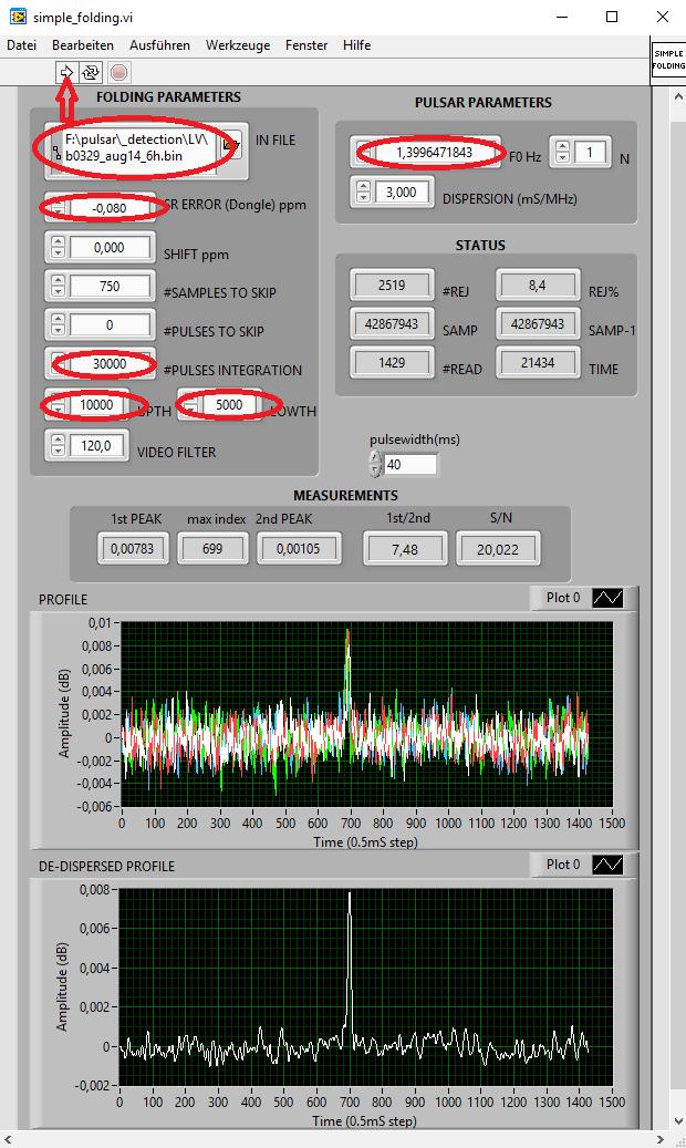
8 As an example I took a 6 hours observation of B I made Aug.14th The value Samples to read is observation time in seconds multiplied by Running the program another time after setting ULIMIT and LLIMIT, the percentage of rejected samples to be 0,14% is indicated. Rather low, although we can see strong RFI. Obviously the interference is short pulses only. Now all is prepared to try to find a pulse in the observation *.BIN file! Open simple_folding, for some values you can use default numbers. Insert the value for #PULSES INTEGRATION, for the B this is 5000 per hour. Then set upper and lower limit from recviewer, in the example and For F0 take Fmean from calculation by tempo (note the difference between the values of Aug.14th to Oct.30th). Now run the program, hopefully you see a pulse! #SAMPLES TO SKIP is for centering the pulse in the display. Especially for long observations the frequency error oft he RTL-SDR can be an issue. In the example the value for compensation is -0,08 ppm. To measure the error of the SDR, I used the ON0EME beacon on 23cm. Any other exact RF source will do the job as well. It is worth the effort to change the parameters in small steps to achieve an improvement of S/N. But stay within +/-1ppm for F0. If you see a pulse for example with F0 offset 10ppm, it is for sure a fake pulse! 8
9 9
, wait until all samples are loaded and now click at the START button (yellow arrow).")
10 A nice tool is also waterfall, insert the same F0, upper and lower limit, ERROR ppm and #SAMPLES TO SKIP as in simple_folding. Then start the program (red arrow), wait until all samples are loaded and now click at the START button (yellow arrow). In the example you see that during the observation there was strong RFI several times. The second part was worse in general, therefore the displayed time is abbreviated. To keep this article short, I did not describe all options in detail. But following the steps, everybody should have first success! Try it and have fun! Special thanks go to Andrea, IW5BHY and his son Giorgio for making the software available!! 10
Amateur Pulsar Detection With EME Equipment
 Amateur Pulsar Detection With EME Equipment Pulsar: Neutron star with offset between magnetic and rotation axis emitting radio waves in a cone (lighthouse effect) Neutron star End of star lifetime: Supernova
Amateur Pulsar Detection. Using the RTL2832U DVB-T. and a 3m Dish
 Amateur Pulsar Detection Using the RTL2832U DVB-T and a 3m Dish Peter East, with assistance from Guillermo Gancio, Michiel Klaassen and Steve Olney Introduction Background Why RTL SDR? RTL Radio Telescope
Lab 4: Measuring Received Signal Power EE 361 Signal Propagation Spring 2017
 Lab 4: Measuring Received Signal Power EE 361 Signal Propagation Spring 2017 This is a one-week lab, plus an extra class period next week outside taking measurements. The lab period is 04-May, and the
N-Channel Scalable Coherent Receiver
 N-Channel Scalable Coherent Receiver Coherent Receiver Family based on the RTL-SDR technology CR0x is an N-channel scalable coherent receiver that employs the RTL-SDR technology in order to create inexpensive
Lab 2: Digital Modulations
 Lab 2: Digital Modulations Due: November 1, 2018 In this lab you will use a hardware device (RTL-SDR which has a frequency range of 25 MHz 1.75 GHz) to implement a digital receiver with Quaternary Phase
Pulsars detection for amateurs
 Pulsars detection for amateurs Mario Armando Natali, I0NAA December 10, 2017 1 Introduction The pulsars, whose name is originated from the contraction of the two words Pulsating Star, are a special class
VK3UM Impedance Calculator. Table of Contents
 Table of Contents Concentric Tube Ratio 3 Centered Strip Line 5 Quarter Wave transition. 6 Coaxial Lengths 7 VSWR Calculator. 8 Dish Reflection Coefficient 10 Convert Fractions to a decimal value. 12 Author
SDR 4++ Dual Diversity SDR Receiver. Operating Guide. version 1.0
 Cross Country Wireless, 7 Thirlmere Grove, BOLTON, BL4 0QB, UK Email chrism@crosscountrywireless.net Web page http://www.crosscountrywireless.net Telephone +44 (0) 1204 410626 Mobile / Workshop +44 (0)
and RTL-SDR Wireless Systems
 Laboratory 4 FM Receiver using MATLAB and RTL-SDR Wireless Systems TLEN 5830 Wireless Systems This Lab introduces the working of FM Receiver using MATLAB and Software Defined Radio This exercise encompasses
Session Three: Pulsar Data and Dispersion Measure
 Slide 1 Session Three: Pulsar Data and Dispersion Measure Sue Ann Heatherly and Sarah Scoles Slide 2 Plot Review Average pulse profile Time domain Reduced χ 2 Recall that last week, we learned about three
The VK3UM Radiation and System Performance Calculator
 The VK3UM Radiation and System Performance Calculator 1. Disclaimer... 2 2. Background... 2 3. Calculations... 2 4. Features... 2 5. Default Parameters... 3 6. Parameter Description... 4 7. On Axis Exclusion
AirScope Spectrum Analyzer User s Manual
 AirScope Spectrum Analyzer Manual Revision 1.0 October 2017 ESTeem Industrial Wireless Solutions Author: Date: Name: Eric P. Marske Title: Product Manager Approved by: Date: Name: Michael Eller Title:
Detection of 21cm Jean-Jacques MAINTOUX - F1EHN
 Detection of Pulsars @ 21cm Jean-Jacques MAINTOUX - F1EHN Pulsar : Pulsating star Table of Contents 1 Signal Research and Choice of Techniques :... 2 1.1 Evaluation : First Reception Test... 2 1.2 Effect
The VK3UM Radiation and System Performance Calculator
 The VK3UM Radiation and System Performance Calculator 1. Disclaimer... 3 2. Background... 3 3. Program Aim... 3 4. Screen Options... 4 5. Features... 5 6. Default Parameters... 6 7. Parameter Descriptions...
Scanning: pictures and text
 Scanning: pictures and text 2010 If you would like this document in an alternative format please ask staff for help. On request we can provide documents with a different size and style of font on a variety
RF-LAMBDA LEADER OF RF BROADBAND SOLUTIONS
 Electrical Specifications Summary The is an easy to use high frequency signal generator controlled through a standard USB port. Using advanced VCO and DDS based technology along with a temperature compensated
Pick a time of day when you can copy WWV 2.5, 5, 10 and 15 MHz, usually late afternoon works for me. (5 p.m.)
") Preparation: Make sure your radio is well warmed up, been on for at least an hour. AGC on Fast, Noise Blankers OFF, RIT OFF, WSJT-X F Tol, set as far open as you can (200) Pick a time of day when you are
Preparation: Make sure your radio is well warmed up, been on for at least an hour. AGC on Fast, Noise Blankers OFF, RIT OFF, WSJT-X F Tol, set as far open as you can (200) Pick a time of day when you are
Introduction to basic laboratory instruments
 BEE 233 Laboratory-1 Introduction to basic laboratory instruments 1. Objectives To learn safety procedures in the laboratory. To learn how to use basic laboratory instruments: power supply, function generator,
IT-24 RigExpert. 2.4 GHz ISM Band Universal Tester. User s manual
 IT-24 RigExpert 2.4 GHz ISM Band Universal Tester User s manual Table of contents 1. Description 2. Specifications 3. Using the tester 3.1. Before you start 3.2. Turning the tester on and off 3.3. Main
Radio Receivers. Al Penney VO1NO
 Radio Receivers Al Penney VO1NO Role of the Receiver The Antenna must capture the radio wave. The desired frequency must be selected from all the EM waves captured by the antenna. The selected signal is
Patrick Lindecker (F6CTE) the 26th of November 2017 EGC EASY WITH MULTIPSK (Version 4.33)
 the 26th of November 2017 EGC EASY WITH MULTIPSK (Version 4.33)") Patrick Lindecker (F6CTE) the 26th of November 2017 EGC EASY WITH MULTIPSK (Version 4.33) Introduction In this document (revision A), it will be found a small guide about : the equipment to use for monitoring
Patrick Lindecker (F6CTE) the 26th of November 2017 EGC EASY WITH MULTIPSK (Version 4.33) Introduction In this document (revision A), it will be found a small guide about : the equipment to use for monitoring
DopplerPSK Quick-Start Guide for v0.20
 DopplerPSK Quick-Start Guide for v0.20 Program Description DopplerPSK is an experimental program for transmitting Doppler-corrected PSK31 on satellite uplinks. It uses an orbital propagator to estimate
Enhancing Analog Signal Generation by Digital Channel Using Pulse-Width Modulation
 Enhancing Analog Signal Generation by Digital Channel Using Pulse-Width Modulation Angelo Zucchetti Advantest angelo.zucchetti@advantest.com Introduction Presented in this article is a technique for generating
PN9000 PULSED CARRIER MEASUREMENTS
 The specialist of Phase noise Measurements PN9000 PULSED CARRIER MEASUREMENTS Carrier frequency: 2.7 GHz - PRF: 5 khz Duty cycle: 1% Page 1 / 12 Introduction When measuring a pulse modulated signal the
Ultra Wide-band Coverage SDR Receiver MK4
 Ultra Wide-band Coverage SDR Receiver MK4 *New What can we listen with DXpatrol? The Dxpatrol can be used as a wide band radio scanner. Applications include: Listening to unencrypted Police/Ambulance/Fire/EMS
Unprecedented wealth of signals for virtually any requirement
 Dual-Channel Arbitrary / Function Generator R&S AM300 Unprecedented wealth of signals for virtually any requirement The new Dual-Channel Arbitrary / Function Generator R&S AM300 ideally complements the
CLOUDSDR RFSPACE #CONNECTED SOFTWARE DEFINED RADIO. final design might vary without notice
 CLOUDSDR #CONNECTED SOFTWARE DEFINED RADIO final design might vary without notice 1 - PRELIMINARY SPECIFICATIONS http://www.rfspace.com v0.1 RFSPACE CloudSDR CLOUDSDR INTRODUCTION The RFSPACE CloudSDR
Technician License Course Chapter 3. Lesson Plan Module 7 Types of Radio Circuits
 Technician License Course Chapter 3 Lesson Plan Module 7 Types of Radio Circuits The Basic Transceiver Combination of transmitter and receiver Abbreviated XCVR (X = trans) Antenna switched between transmitter
3 GHz Carrier Backhaul Radio. Model: AF-3X. Tel: +44 (0) Fax: +44 (0) LINK GPS MGMT DATA DATA
 Fax: +44 (0) LINK GPS MGMT DATA DATA") LINK GPS MGMT DATA DATA MGMT GPS LINK 3 GHz Carrier Backhaul Radio Model: AF-3X LINK GPS MGMT DATA 3 GHz Carrier Backhaul Radio Model: AF-3X LINK GPS MGMT DATA DATA MGMT GPS LINK Introduction Thank you
LINK GPS MGMT DATA DATA MGMT GPS LINK 3 GHz Carrier Backhaul Radio Model: AF-3X LINK GPS MGMT DATA 3 GHz Carrier Backhaul Radio Model: AF-3X LINK GPS MGMT DATA DATA MGMT GPS LINK Introduction Thank you
Transceiver. Quick Start Guide. What is in the box What does it do How to build a setup Verification of the setup...
 Transceiver Quick Start Guide What is in the box... 3 What does it do... 5 How to build a setup... 6 Verification of the setup... 10 Help and troubleshooting... 11 Technical specifications... 12 Declaration
2.3GHz Dish Feed Antenna
 I have not been convinced my very old 2.3GHz 44 element Loop Yagi has been working as well as it should do, particularly as the elements have become severely corroded over the years. I decided to see if
Quiver User Guide. Xcor-QUG-v /13/12
 Quiver User Guide Xcor-QUG-v.3.0.4 8/13/12 This document details the full features and functionality of Quiver. Included is information on the various modes of operation and instruction on how to best
DEM A32 Synthesizer. /PD/A32-pd.doc x 1 Rev. A 7/24/12
 DEM A32 Synthesizer The DEM A32 is a preprogrammed 750-1300 MHz. synthesizer designed exclusively for DEMI by N5AC. This synthesizer is a derivative of his original USB controllable ApolLO-1 design. The
Final Report (Group 15-22)
") Group 15-22 Ultrasound Imaging 1 Final Report (Group 15-22) Ultrasound Imaging System Project members Advisor and Client: Timothy Bigelow bigelow@iastate.edu Aaron Tainter (Programming) atainter@iastate.edu
Group 15-22 Ultrasound Imaging 1 Final Report (Group 15-22) Ultrasound Imaging System Project members Advisor and Client: Timothy Bigelow bigelow@iastate.edu Aaron Tainter (Programming) atainter@iastate.edu
Ground System Training Department
 Module 7: IPSTAR Uplink Access Test (IUAT) Ground System Training Department 2012-03-Standard (iuat1.14)-uti-101 THAICOM Public Company Limited Module Objectives At the end of the module the participant
Software Defined Radio. Bella Vista Radio Club 1 February 2018
 Software Defined Radio Bella Vista Radio Club 1 February 2018 Agenda for Software Defined Radio (SDR) What is it? How does it work? Demonstration. How do you hook it up? What hardware is available (Cost)?
Norfolk Amateur Radio Club
 Norfolk Amateur Radio Club The Transmitter & Transmitter Interference Nick M0HGU & Steve G3PND Plan for the Day The Transmitter Introduction, Block diagrams Oscillators, Buffers & Multipliers Modulation
Radio Receivers. Al Penney VO1NO
 Radio Receivers Role of the Receiver The Antenna must capture the radio wave. The desired frequency must be selected from all the EM waves captured by the antenna. The selected signal is usually very weak
DopplerPSK Quick-Start Guide for v0.10
 DopplerPSK Quick-Start Guide for v0.10 Program Description DopplerPSK is an experimental program for transmitting Doppler-corrected PSK31 on satellite uplinks. It uses an orbital propagator to estimate
A SDR-based receiver for Es hail-2 and the BACAR 6, 10 GHz beacons 30 July 2018
 A SDR-based receiver for Es hail-2 and the BACAR 6, 10 GHz beacons 30 July 2018 Hannes Coetzee, ZS6BZP Introduction If all goes according to plan the Qatar Satellite Company (Es hailsat) will place its
by Cliff Pulis, KE0CP SDR Presentation - Cliff Pulis, KE0CP 1
 by Cliff Pulis, KE0CP SDR Presentation - Cliff Pulis, KE0CP 1 Basic Receiver Principles Mixing Frequencies Hetrodyn ing The IF Amplifier SDR Principles & Quadrature Phase (IQ) VHF / UHF DVB-T Dongle SDR
Using Signal Studio Waveform Licenses. Procedure
 Using Signal Studio Waveform Licenses Procedure This Document This document describes how to: Use the Signal Studio software to configure, generate, and download waveform files to your instrument Play
Resonant Antennas: Wires and Patches
 Resonant Antennas: Wires and Patches Dipole Antennas Antenna 48 Current distribution approximation Un-normalized pattern: and Antenna 49 Radiating power: For half-wave dipole and,, or at exact resonance.
by Robert A. Landry, Central Mass Caricature Carvers, 12/5/14, Rev A
 FaceGen Modeler by Robert A. Landry, Central Mass Caricature Carvers, 12/5/14, Rev A If you are interested in creating a bust, or a bottle stopper carving please consider using the following software.
Software Defined Radio hardware for Osmocom BTS. Alexander Chemeris CTO, Fairwaves, Inc.
 Software Defined Radio hardware for Osmocom BTS Alexander Chemeris CTO, Fairwaves, Inc. CC BY 4.0 Software Defined Radio (SDR): a sound-card for radio waves 0 1 0 1 0 1 digital IQ samples radio signal
USB-UT350(T) Portable Ultrasonic Pulser/Receiver and Analog to Digital Converter. User s Guide
 Portable Ultrasonic Pulser/Receiver and Analog to Digital Converter. User s Guide") USB-UT350(T) Portable Ultrasonic Pulser/Receiver and Analog to Digital Converter User s Guide 2000-2009 US Ultratek, Inc. Revision 1.77 September 30, 2009 US Ultratek, Inc. 4070 Nelson Ave., Suite B Concord,
USB-UT350(T) Portable Ultrasonic Pulser/Receiver and Analog to Digital Converter User s Guide 2000-2009 US Ultratek, Inc. Revision 1.77 September 30, 2009 US Ultratek, Inc. 4070 Nelson Ave., Suite B Concord,
Range Considerations for RF Networks
 TI Technology Days 2010 Range Considerations for RF Networks Richard Wallace Abstract The antenna can be one of the most daunting components of wireless designs. Most information available relates to large
SATELLITES WITH A COLLINEAR ANTENNA
 SATELLITES WITH A COLLINEAR ANTENNA Juan Antonio Fernández Montaña EA4CYQ Radio amateurs have not yet been able to cross the Atlantic Ocean in the high bands (145 MHz up), but we have to say in terrestrial
Keywords: GPS, receiver, GPS receiver, MAX2769, 2769, 1575MHz, Integrated GPS Receiver, Global Positioning System
 Maxim > Design Support > Technical Documents > User Guides > APP 3910 Keywords: GPS, receiver, GPS receiver, MAX2769, 2769, 1575MHz, Integrated GPS Receiver, Global Positioning System USER GUIDE 3910 User's
Signal Safari. Welcome! Curious about RF? Looking for awesome new projects? Seeking adventure?
 ++ BSidesNYC 2018 Welcome! Curious about RF? Looking for awesome new projects? Seeking adventure? + Agenda + Safari Guide + RF Overview / Exploration + GQRX + Light Switch Reversing + RTL_433 + Fan Controller
6.S02 MRI Lab Acquire MR signals. 2.1 Free Induction decay (FID)
") 6.S02 MRI Lab 1 2. Acquire MR signals Connecting to the scanner Connect to VMware on the Lab Macs. Download and extract the following zip file in the MRI Lab dropbox folder: https://www.dropbox.com/s/ga8ga4a0sxwe62e/mit_download.zip
6.S02 MRI Lab 1 2. Acquire MR signals Connecting to the scanner Connect to VMware on the Lab Macs. Download and extract the following zip file in the MRI Lab dropbox folder: https://www.dropbox.com/s/ga8ga4a0sxwe62e/mit_download.zip
QUICK START GUIDE FOR DEMONSTRATION CIRCUIT BIT DIFFERENTIAL INPUT DELTA SIGMA ADC LTC DESCRIPTION
 LTC2433-1 DESCRIPTION Demonstration circuit 745 features the LTC2433-1, a 16-bit high performance Σ analog-to-digital converter (ADC). The LTC2433-1 features 0.12 LSB linearity, 0.16 LSB full-scale accuracy,
GXCapture 8.1 Instruction Manual
 GT Vision image acquisition, managing and processing software GXCapture 8.1 Instruction Manual Contents of the Instruction Manual GXC is the shortened name used for GXCapture Square brackets are used to
SonoLab Echo-I User Manual
 SonoLab Echo-I User Manual Overview: SonoLab Echo-I is a single board digital ultrasound pulse-echo solution. The system has a built in 50 volt high voltage generation circuit, a bipolar pulser, a transmit/receive
EME ON 77.5 Ghz. Sergei RW3BP, EME Meeting in Orebro, Sweden, May First of all few words about difficulties we have for EME on this band.
 EME ON 77.5 Ghz Sergei RW3BP, EME Meeting in Orebro, Sweden, May 2013. First of all few words about difficulties we have for EME on this band. You can see formula for signal to noise ratio. It is based
QUICK START GUIDE FOR DEMONSTRATION CIRCUIT BIT, 250KSPS ADC
 DESCRIPTION QUICK START GUIDE FOR DEMONSTRATION CIRCUIT 1255 LTC1605CG/LTC1606CG The LTC1606 is a 250Ksps ADC that draws only 75mW from a single +5V Supply, while the LTC1605 is a 100Ksps ADC that draws
PXIe Contents CALIBRATION PROCEDURE
 CALIBRATION PROCEDURE PXIe-5632 This document contains the verification and adjustment procedures for the PXIe-5632 Vector Network Analyzer. Refer to ni.com/calibration for more information about calibration
Select the Right Operational Amplifier for your Filtering Circuits
 Select the Right Operational Amplifier for your Filtering Circuits 2003 Microchip Technology Incorporated. All Rights Reserved. for Low Pass Filters 1 Hello, my name is Bonnie Baker, and I am with Microchip.
VDSL2 radiation and its signal characterisation
 VDSL2 radiation and its signal characterisation Overview The EMC committee of the Radio Society of Great Britain has been monitoring sources of RFI for many years. A particular problem for HF communications
5008 Dual Synthesizer Configuration Manager User s Guide (admin Version) Version valontechnology.com
 Version valontechnology.com") 5008 Dual Synthesizer Configuration Manager User s Guide (admin Version) Version 1.6.1 valontechnology.com 5008 Dual Synthesizer Module Configuration Manager Program Version 1.6.1 Page 2 Table of Contents
5008 Dual Synthesizer Configuration Manager User s Guide (admin Version) Version 1.6.1 valontechnology.com 5008 Dual Synthesizer Module Configuration Manager Program Version 1.6.1 Page 2 Table of Contents
Screen shots vary slightly according to Windows version you have.
 http://www.w1hkj.com/fldigihelp/audio_adjust_page.html Screen shots vary slightly according to Windows version you have. Receive audio Setting the correct hardware, operating system, and fldigi received
Electronics Design Laboratory Lecture #10. ECEN 2270 Electronics Design Laboratory
 Electronics Design Laboratory Lecture #10 Electronics Design Laboratory 1 Lessons from Experiment 4 Code debugging: use print statements and serial monitor window Circuit debugging: Re check operation
Optika ISview. Image acquisition and processing software. Instruction Manual
 Optika ISview Image acquisition and processing software Instruction Manual Key to the Instruction Manual IS is shortened name used for OptikaISview Square brackets are used to indicate items such as menu
SCD-0017 Firegrab Documentation
 SCD-0017 Firegrab Documentation Release XI Tordivel AS January 04, 2017 Contents 1 User Guide 3 2 Fire-I Camera Properties 9 3 Raw Color Mode 13 4 Examples 15 5 Release notes 17 i ii SCD-0017 Firegrab
Specifications Sheet: PRIME FOCUS MESH DISH KIT 1.2 Meter DISH
 Specifications Sheet: PRIME FOCUS MESH DISH KIT 1.2 Meter DISH Available F/D: 0.35 / 0.4 / 0.45 / 0.5 (Example Picture: 1.2 Meter dish (6mm mesh) 1M2_KIT_SPEC RF HAMDESIGN www.rfhamdesign.com This 8-Rib
MESA-HPX. Assembly and Installation Manual. w/appendix A for Prodelin Antenna. 901-Manual-MESA-HPX
 MESA-HPX Assembly and Installation Manual w/appendix A for Prodelin Antenna 901-Manual-MESA-HPX Rev 30 March 2011 2 INDEX Installation Cautions 4 Installation Pole Height Orientation of the Mount on the
Ascent Ground and Satellite Demonstration
 Ascent Ground and Satellite Demonstration By Ray Roberge, WA1CYB & Howie DeFelice, AB2S WA1CYB s1 Big Picture Goals Place more capable satellites into higher orbits Utilize software defined radios A programmable
Cisco CleanAir Accessory for Chanalyzer
 Cisco CleanAir Accessory for Chanalyzer System Requirements SOFTWARE: Chanalyzer 5 OPERATING SYSTEM: Microsoft Windows 8, 7, Vista * * support for XP (SP3) to be announced Mac OS X VIRTUALIZATION: VMware
Heterodyne Sweeping Radiometer
 46 Robezu str. LV-1004 Riga, Latvia Fax: +371-7-065102 Mm-wave Division in St. Petersburg, Russia Fax: +7-812- 326-10-60 Tel: +7-812-326-59-24 E-mail: ivanovph@nnz.ru Heterodyne Sweeping Radiometer Operation
User Manual Rev 3.5 SmartRF Studio 4.50
 User Manual Rev 3.5 SmartRF Studio 4.50 Chipcon AS, Gaustadalléen 21, N-0349 Oslo, Norway, Tel: (+47) 22 95 85 45, Fax: (+47) 22 95 85 46 E-mail: support@chipcon.com Table of contents 1 INTRODUCTION...
Vela Pulsar Project Early Results
 Vela Pulsar Project Early Results Steve Olney (VK2XV) NRARAO 13th April 2015 Some encouraging results are described and possible future developments Introduction main GUI overview. As you can see there
SIGNAL GENERATORS. MG3633A 10 khz to 2700 MHz SYNTHESIZED SIGNAL GENERATOR GPIB
 SYNTHESIZED SIGNAL GENERATOR MG3633A GPIB For Evaluating of Quasi-Microwaves and Measuring High-Performance Receivers The MG3633A has excellent resolution, switching speed, signal purity, and a high output
Using Wavemaker: A Guide to Creating Arbitrary Waveforms for Syscomp CircuitGear and Waveform Generators
 Using Wavemaker: A Guide to Creating Arbitrary Waveforms for Syscomp CircuitGear and Waveform Generators Peter D. Hiscocks Syscomp Electronic Design Limited phiscock@ee.ryerson.ca www.syscompdesign.com
PXA Configuration. Frequency range
 Keysight Technologies Making Wideband Measurements Using the Keysight PXA Signal Analyzer as a Down Converter with Infiniium Oscilloscopes and 89600 VSA Software Application Note Introduction Many applications
USB Multifunction Arbitrary Waveform Generator AWG2300. User Guide
 USB Multifunction Arbitrary Waveform Generator AWG2300 User Guide Contents Safety information... 3 About this guide... 4 AWG2300 specifications... 5 Chapter 1. Product introduction 1 1. Package contents......
DAC1627D Demo boards Quick Start v2
 DAC1627D Demo boards Quick Start v2 1 DAC1627D demoboard+ CGAP2 Board presentation CGAP2 board: Storage and Generation of complex patterns up to 32M (I,Q)- words DAC1627D board 2 DAC1627D demoboard+ CGAP2
FLATBED MEMORIES Working with Your Scanner
 FLATBED MEMORIES Working with Your Scanner Scanners are both extremely useful and about as cheap a peripheral device as you can get. They allow you to take either images or pages of text and input them
II. LAB. * Open the LabVIEW program (Start > All Programs > National Instruments > LabVIEW 2012 > LabVIEW 2012)
") II. LAB Software Required: NI LabVIEW 2012, NI LabVIEW 4.3 Modulation Toolkit. Functions and VI (Virtual Instrument) from the LabVIEW software to be used in this lab: niusrp Open Tx Session (VI), niusrp
II. LAB Software Required: NI LabVIEW 2012, NI LabVIEW 4.3 Modulation Toolkit. Functions and VI (Virtual Instrument) from the LabVIEW software to be used in this lab: niusrp Open Tx Session (VI), niusrp
Trimble S6 Robotic Total Station Field Guide Provided by: California Surveying & Drafting Supply Technical Support Services
 Trimble S6 Robotic Total Station Field Guide Provided by: California Surveying & Drafting Supply Technical Support Services Table of Contents: Procedure: Page: Field Checklist 2 Setting Up Your Trimble
3 USRP2 Hardware Implementation
 3 USRP2 Hardware Implementation This section of the laboratory will familiarize you with some of the useful GNURadio tools for digital communication system design via SDR using the USRP2 platforms. Specifically,
Antenna and Propagation
 Antenna and Propagation This courseware product contains scholarly and technical information and is protected by copyright laws and international treaties. No part of this publication may be reproduced
The DesignaKnit USB E6000 Link 1 & 2
 The DesignaKnit USB E6000 Link 1 & 2 for the Passap / Pfaff Electronic 6000 USB E6000 Link 1 USB E6000 Link 2 What these links do The USB E6000 Link 1 enables downloading of stitch patterns from DesignaKnit
Characteristics of HF Coastal Radars
 Function Characteristics System 1 Maximum operational (measurement) range** Characteristics of HF Coastal Radars 5 MHz Long-range oceanographic 160-220 km average during (daytime)* System 2 System 3 System
Pulse Doppler Flow-Dop
 EDUCATION Pulse Doppler Flow-Dop GAMPT-50100 User Manual Fon: +49 (0) 3461-278 691-0 Fax: +49 (0) 3461-278 691-101 email: info@gampt.de Gesellschaft für Angewandte Medizinische Physik und Technik mbh (GAMPT
Analog Devices Welcomes Hittite Microwave Corporation NO CONTENT ON THE ATTACHED DOCUMENT HAS CHANGED
 Analog Devices Welcomes Hittite Microwave Corporation NO CONTENT ON THE ATTACHED DOCUMENT HAS CHANGED www.analog.com www.hittite.com THIS PAGE INTENTIONALLY LEFT BLANK HMC6383 Evaluation Kit Analog, Digital
Weather Satellite Receiver APT-06 / APT-06 AD Operating Manual
 Weather Satellite Receiver APT-06 / APT-06 AD Operating Manual WRAASE electronic WeSaCom-Systems Kronsberg 10 24161 Altenholz Tel. 0431 32528 Fax 0431 32579 www.wesacom.de E-mail: info@wesacom.de 1 Weather
To: Deuterium Array Group From: Alan E.E. Rogers, K.A. Dudevoir and B.J. Fanous Subject: Low Cost Array for the 327 MHz Deuterium Line
 DEUTERIUM ARRAY MEMO #068 MASSACHUSETTS INSTITUTE OF TECHNOLOGY HAYSTACK OBSERVATORY WESTFORD, MASSACHUSETTS 01886 August 2, 2007 Telephone: 978-692-4764 Fax: 781-981-0590 To: Deuterium Array Group From:
Module 8 Theory. dbs AM Detector Ring Modulator Receiver Chain. Functional Blocks Parameters. IRTS Region 4
 Module 8 Theory dbs AM Detector Ring Modulator Receiver Chain Functional Blocks Parameters Decibel (db) The term db or decibel is a relative unit of measurement used frequently in electronic communications
EU1 OPERATION MANUAL
 EU1 OPERATION MANUAL A. Install the USB driver on the windows Download the windows driver for CP2102, and Plug the USB programmer and install the driver, then after installed the driver, from the windows
APNT#1166 Banner Engineering Driver v How To Guide
 Application Note #1166: Banner Engineering Driver v1.10.02 How To Guide Introduction This Application Note is intended to assist users in using the GP-Pro EX Version 2..X\2.10.X Banner Engineering Corp.
VB-99 V-Bass System. On-the-Gig Sound Settings. Workshop ÂØÒňΠVB99WS03
 ÂØÒňΠWorkshop VB-99 V-Bass System On-the-Gig Sound Settings 009 Roland Corporation U.S. All rights reserved. No part of this publication may be reproduced in any form without the written permission of
My experience with the ANC-4 on 50 MHz Rev. 1
 My experience with the ANC-4 on 50 MHz Rev. 1 by Antonio Vernucci, I0JX 1. General The ANC-4 (Antenna Noise Canceller - 4) is intended to reduce the impairment of weak DX signals reception caused by local
BUILD A 10 MHZ EXTERNAL REFERENCE DEVICE PART 2
 First published in the July-August 2016 issue of The Canadian Amateur BUILD A 10 MHZ EXTERNAL REFERENCE DEVICE PART 2 Special thanks to Brian Grant, VE3GEN, in providing the initial information for this
DSA-815 Demo Guide. Solution: The DSA 800 series of spectrum analyzers are packed with features.
 FAQ Instrument Solution FAQ Solution Title DSA-815 Demo Guide Date:08.29.2012 Solution: The DSA 800 series of spectrum analyzers are packed with features. Spectrum analyzers are similar to oscilloscopes..
Phone:
 Email: Support@signalforge.com Phone: 512.275.3733 Web: www.signalforge.com Customer Service Email: Sales@signalforge.com Phone: 512.275.3733 Fax: 512.275.3735 Address: Signal Forge, LLC 2115 Saratoga
Build your own SDR. By Julie VK3FOWL and Joe VK3YSP
 2018 Build your own SDR By Julie VK3FOWL and Joe VK3YSP Introduction Why build your own Software Defined Radio? Learn about Digital Signal Processing, GNU Radio Flow Graphs, IQ, Linux and Python Create
Signal Generators for Anritsu RF and Microwave Handheld Instruments
 Measurement Guide Signal Generators for Anritsu RF and Microwave Handheld Instruments BTS Master Spectrum Master Tracking Generator Option 20 Vector signal Generator Option 23 Anritsu Company 490 Jarvis
RECOMMENDATION ITU-R SM Method for measurements of radio noise
 Rec. ITU-R SM.1753 1 RECOMMENDATION ITU-R SM.1753 Method for measurements of radio noise (Question ITU-R 1/45) (2006) Scope For radio noise measurements there is a need to have a uniform, frequency-independent
NI USRP Lab: DQPSK Transceiver Design
 NI USRP Lab: DQPSK Transceiver Design 1 Introduction 1.1 Aims This Lab aims for you to: understand the USRP hardware and capabilities; build a DQPSK receiver using LabVIEW and the USRP. By the end of this
Example running cadrcs adding RAM material on a ship.
 1 Example running cadrcs adding RAM material on a ship. Step1 identifying the Hot Spots. Start cadrcs and accept the license agreement. Go to: File - > Project name and working directory Choose a directory