18-Channel Digital Proportional R/C System INSTRUCTION MANUAL
|
|
|
- Anastasia Francis
- 5 years ago
- Views:
Transcription


1 INSTRUCTION MANUAL
2 TABLE OF CONTENTS INTRODUCTION
3 TABLE OF CONTENTS
4 INTRODUCTION
5 IC
6
7 Application, Export, and Modification Precautions. 1. This product is only designed for use with radio control models. Use of the product described in this instruction manual is limited to radio control models. 2. Export precautions: a) When this product is exported, it cannot be used where prohibited by the laws governing radio waves of the destination country. b) Use of this product with other than models may be restricted by Export and Trade Control Regulations. 3. Modification, adjustment, and parts replacement: Futaba is not responsible for unauthorized modification, adjustment, or replacement of parts on this product. Please observe the following precautions to ensure safe use of this product at all times. Meaning of Special Markings: The parts of this manual indicated by the following marks require special attention from the standpoint of safety.
8
9
10
11 BEFORE USE FASSTest system The T16SZ transmitter has adopted the bidirectional communication system "FASSTest". Data from the receiver can be checked in your transmitter. FASSTest is a maximum 18 channels 2.4GHz dedicated system. Color touch screen LCD enables both indoor and outdoor visibility. S.BUS2 system minimum amount of cables. Model types are available for airplanes and gliders. Functions and mixing functions necessary for each model type are set in advance at the factory. NiMH battery T16SZ is operated by a 6.0 V/1,800 mah NiMH battery. SD card (Secure Digital memory card) (Not included) Model data can be saved to an SD card (SD:32MB-2GB SDHC:4GB-32GB). When T16SZ transmitter Edit button sensor. Vibration function Selects a function that alerts the operator to various alarms by vibrating the transmitter in addition to sounding a buzzer. Speech function
12 Note: The battery in the T16SZ transmitter does not arrive already attached to the battery connector. Please connect the battery connector before use.
13 Optional Parts The following additional accessories are available from your dealer. Refer to a Futaba catalog for more information: HT5F1800B transmitter battery pack - the (1,800mAh) transmitter NiMH battery pack may be easily Trainer cord - the optional training cord may be used to help a beginning pilot learn to fly easily by placing the instructor on a separate transmitter. Note that the T16SZ transmitter may be connected to Servos - there are various kinds of servos. Please choose the Futaba servos that best suit your model and used if "FASSTest12CH mode" is used. Telemetry sensor - please purchase an optional sensor, in order to utilize bidirectional communication system and to acquire the information from a model high up in the sky. magnet type : SBS- Neckstrap - a neckstrap may be connected to your T16SZ system to make it easier to handle and improve Y-harnesses, servo extensions, hub,etc - Genuine Futaba extensions and Y-harnesses, including a heavy- Gyros - a variety of genuine Futaba gyros is available for your aircraft or helicopter needs. FASSTest and FASST, T-FHSS, S-FHSS types are available.) SBD-2, S.BUS decoder -The SBD-2 is a converter for using conventional servos (other than an S.BUS system and eight servos can be used. SBD-2 can change the output CH by selecting from 9 groups using

14
15 The antenna can be rotated 180 degrees and angles 90 degrees. Forcing the antenna further than this can damage it. The antenna is not removable.
16 *Self retum
17 analog input. knob reaches the center position. *You can use each setting screen of the mixing functions to select volumes and define the direction of movement. *You can select a slide lever and set the movement direction on the setting screen of mixing functions.
18 referencing the LCD screen. *You can select the trim step amount and the display unit linkage menu.
19
20 Note: If you remove the battery while the power is on, the data you have set will not be saved. 1. Open the battery cover. 2. Disconnect the battery connector. 3. Close the battery cover completely. 1.Plug the transmitter cord of the special charger into the charging jack on the side of the transmitter. 2. Plug the charger into an AC outlet. 3. Check that the charging LED lights. hours. 4. Disconnect the charge plug. 5. Disconnect the AC plug. move the battery and transmitter from the charger cling several times if the battery has not been used for a long period. performance of the battery if you have used the battery only for a short period or if you repeat charging gested to discharge the battery to the recommended
21 part of the front of a T16SZ.
22 data. be careful so that you don't scratch the Touch Panel anything on the panel. plastic panel due to environmental changes such problems. pixels hold lighting. Moreover, some pixels go out. And a screen may flicker. Such condition is the HOME/EXIT U.MENU/MON.

23 Temporarily activating this function makes it impossible to change data by mistakenly touching keys How to lock 1. The home screen is displayed. 2. Press the HOME/EXIT button for about 1 second. "Key mark" is displayed and the keys disabled. How to unlock 1. Press the Home/Exit button for about 1 second, and the panel will then become unlocked.

24
25
26
27
28 *In case of mode 1 2. Next, using a hand, remove the transmitter's side cover (rubber). When using Mode 1, you will need to remove the side cover to expose the tension screw. head "A" counter-clockwise. The lock will be released. 2. Turn the lever-head "A" clockwise as you hold It is only the mode 1 3. Using your hand remove the transmitter's rear rubber grips. The tension of the self-return type stick lever can 1. First, remove the battery cover on the bottom of the transmitter. Next, unplug the battery wire and remove the battery from the transmitter.
 (Mode 2) Stick Tension (J3) (Mode 1) 5.")
29 Stick Tension (J1) (Mode 1/2) Stick Tension (J4) (Mode 1/2) 4. Use a screw driver to adjust the spring strength as you prefer by turning the adjusting screw of the stick you want to adjust. CAUTION: Loosening the screw too much can interfere with the internal stick operation. Stick Tension (J2) (Mode 2) Stick Tension (J3) (Mode 1) 5. At the end of adjustment, re-install the side cover and rear grips. The T16SZ transmitter model data can be stored by using any commonly found SD card. When capable of using SD and SDHC cards (SD:32MB-2GB SDHC:4GB-32GB). Saving model data and update files (released from Futaba) into the SD card, you can use those electronics stores. When you have a problem of saving or reading card. *We are not responsible for, and offer no compensation for, memory card data that fails or is damaged for any reason. Be sure to keep a backup of all important data stored in your SD card.
30 -When an SD card is installed in the T16SZ transmitter, a folder called "Futaba" is cre- folder stores the telemetry log data. SD card slot -The telemetry log data recorded on the SD card can be converted to CSV format by the telemeter log converter released on our home page. When copying or moving a log SD card slot
31 When using an S.BUS servo and telemetry sensor, connect them both here. Earphone Plug Charge Plug Connecting a stereo headphone to this plug, the speech information of telemetry can be heard. This is the connector for charging the NiMH battery HT5F1800B that is installed in the transmitter. Do not use any other chargers except the attached special charger corresponding to NiMH battery. Trainer Connector S.BUS (S.I/F) Connector When you use the trainer function, connect the teacher and student. *You can set the trainer function on the Trainer Function screen in the System menu.
32 Before using the receiver, be sure to read the Connector "1 through 6": outputs for the channels 1 through 6 "8/SB": outputs of 8 channels or S.BUS port. [S.BUS Servo S.BUS Gyro ] *When using 8/SB as S.BUS, you have to set mode D. "S.BUS2": outputs of S.BUS2 port. [S.BUS2 Servo S.BUS2 Gyro Telemetry Sensor ] *When using 9 or more channels, use an S.BUS both to your transmitter. connected to the S.BUS2 ports on any receiver. LED Monitor This monitor is used to check the CH mode of the receiver. Link/Mode Switch mode selection. Connector insertion Firmly insert the connector in the direction it 90 degrees. Do not connect either a switch or battery in this manner. Extra Voltage Connector telemetry device to send the battery voltage (DC0
33 outputs. Additionally the PWM outputs can be you only desire to use it as an 8 channel receiver setting changes. channels 1-8 and the other outputting channels for this configuration and S.BUS operation R7008SB CH MODE TABLE 1. Press and hold down the Link/Mode button 2. Turn the receiver on while holding down the Link/Mode button. When the LED begins to blink green/red the button may be released. 3. The LED should now be blinking red in one of the patterns described by the chart below. 4. Each press of the Mode/Link button advances the receiver to the next mode. 5. When you reach the mode that you wish to operate in, press and hold the Mode/ Link button for more than 2 seconds. 6. Once locked into the correct mode the LED will change to a solid color. 7. Please cycle the receiver(s) power off and back on again after changing the Channel Mode.
34 *Must be kept as straight as possible. Antenna Coaxial cable To obtain the best results of the diversity instructions: 1. The two antennas must be kept as straight as possible. Otherwise it will reduce the effective range. 2. The two antennas should be placed at 90 degrees to each other. R7008SB Receiver This is not a critical figure, but the most important thing is to keep the antennas away from each other as much as possible. Larger models can have large metal objects that can weaken the RF signal. In this case the antennas should be placed at both sides of the model. Then the best attitude. 3. The antennas must be kept away from conductive materials, such as metal, carbon and fuel tank, by at least half an inch. The coaxial part of the antennas does not need to follow these guidelines, but do not bend it in a tight radius. 4. Keep the antennas away from the motor, ESC, and other noise sources as much as possible. Antenna Antenna
35 Wood screw Rubber grommet Brass eyelet Servo mount (Airplane/Glider) mm nut washer Rubber grommet Brass eyelet Servo mount mm screw (Helicopter) To prevent the servo lead cable from being broken by vibration during flight, provide a little slack in the cable and fasten it at suitable points. Periodically check the cable during daily maintenance. Margin in the lead wire. Fasten about 5-10cm from the servo outlet so that the lead wire is neat and secure. airframe, make a rectangular hole that is a little binding.
36 number of servos used.
37 *When using 8/SB as S.BUS, you must set the receiver to Mode B or Mode D. See R7008SB CH MODE TABLE. Page 33 Since the channel number is memorized by the S.BUS itself, any connector can be used. When the SBD-1, SBD-2 (sold separately) is used, ordinary servos can be used with the S.BUS system. *SBD-1 S.BUS Decoders cannot be used by S.BUS2 port. Optional Parts Six connectors can be inserted Used when using a separate power supply battery. Three connectors can be inserted. When a large number of servos are used or when high current servos are used, the servos can be driven by a separate power supply by using a separate Power Supply 3-way hub with orange connector. *When using 8/SB as S.BUS, you must set the receiver to Mode B or Mode D. See R7008SB CH MODE TABLE.
38 When using the S.BUS2 port, an impressive array of telemetry sensors may be utilized. S.BUS2 TABLE S.BUS servos and gyros and S.BUS2 servos and gyros must be used in the correct receiver ports. Please refer to the instruction manual to make sure you connect to the correct one.
39 S.BUS/S.BUS2 servos or a telemetry sensor can be connected directly to the T16SZ. Channel setting and other data can be entered for the S.BUS/S.BUS2 servos or sensors. 2. Turn on the transmitter power. 3. Call the setup screen. Servo: System Menu Sensor: Linkage Menu Sensor 4. Perform setting in accordance with each screen. 5. This sets the channel and other data for each
40 Battery voltage for receivers In FASSTest/T-FHSS mode, it is displayed. Receiver voltage and Ext voltage display BASIC OPERATION This is the Home screen and descriptions of its menus. Use your finger to operate the touch screen. Condition name The condition name that is currently used is displayed here. Battery Indicator When the battery voltage reaches 5.8V, the alarm will beep. Land your aircraft immediately. Model Tap the button to call Model Menu screen. System mode System(FASSTest18CH etc.) mode is displayed here. The reception of the signal from the receiver to the transmitter is shown. Timer1, Timer2 Timer is displayed here. Tap the time button to start/stop the timer. (When the screen is tapped for 1 second, timer is reset to the initial value.) User's name RF Indicator Model Name The model name that is currently used is displayed here. System Linkage Model select Tap the button to call each Menu screen. System timer This shows the accumulated time since the latest reset. (Each model / Total) (Hour):(Minute):(Second) Digital trim (T1 to T4) Trim position is displayed here.

41 Each transmitter has an individually assigned, unique ID code. In order to start operation, the receiver must be linked with the ID code of the transmitter to which it is being paired. Once the link is made, the ID code is stored in the receiver and no further linking is necessary unless the receiver is to be used with another transmitter. When you purchase additional R7008SB receivers, this procedure is necessary; otherwise the receiver will not work. 1. Place the transmitter and the receiver close to each other within half (0.5m) meter. 6.[Link] is tapped. The transmitter will emit a chime as it starts the linking process. 2. Turn on the transmitter. 3. Select [System type] at the Linkage menu and access the setup screen shown below by tapping the screen. 7. When the transmitter starts to chime, power on the receiver. The receiver should link to the transmitter within about 1 second. 4. When you use two receivers on one model, you must change from [Single] to [Dual]. *Only two receivers can be used. In "Dual", two setting items come out. Input, respectively. ID of a primary receiver displays. ID of a secondary receiver displays. In Dual, a primary receiver (Rx1) is linked first. Next, a secondary (Rx2) receiver is linked. 5. Battery fail-safe voltage can be changed from the initial value of 3.8V here. * Only in FASSTest/T-FHSS Mode. 8. If linking fails, an error message is displayed. Bring the transmitter closer to the receiver and repeat the procedure above from Step 2.
42 9. ACT will be chosen if telemetry is used. It is INH when not using it. 10. When a telemetry function is enabled, the receiving interval (down-link interval) of sensor data can be changed. If a D/ L interval is increased, the response of the sensor data display becomes slower, but stick response will improve. Initial value: 1.0s Adjustment range: 0.1s~2.0s setup a "Rx1" and "Rx2" in the "dual" mode. *Telemetry function cannot be used for the 2nd receiver. FASSTest18CH *Telemetry function cannot be used for the dual receiver. T-FHSS, FASSTest12CH *You must link one receiver at a time. If both power supplies to the receivers are switched on simultaneously, data is received incorrectly by the transmitter. *You cannot link three receivers. *Link is required when a system type is changed. *Linking is required whenever a new model is made. *If there are many FASSTest (T-FHSS) systems turned on around your receiver, it might not link to your transmitter. In this case, even if the receiver's LED stays solid green, unfortunately the receiver might have established a link to one of other transmitters. This is very dangerous if you do not notice this situation. In order to avoid the problem, we strongly recommend you to double check whether your receiver is really under control by your transmitter by giving the stick input and then checking the servo response. *Do not perform the linking operation when the drive motor is connected or the engine is running. *When you use two receivers, please be sure to
43


44 transmitter incorporates a system that reduces its power output and allows you to perform such a range check. During this mode, the RF power output is reduced so the range test can be performed. In addition, when this mode is activated the right LED on the front of the transmitter starts blinking and the transmitter gives users a warning with a beeping sound. and after that the power will return to the normal level. press the "HOME/EXIT" button. NEVER start flying when the "Range check mode" is active. Should you require additional time to perform a range check, highlight Restart before your time expires and tap the screen one time. 1. With the "Range check mode" on, walk away from the model while simultaneously operating the controls. Have an assistant stand by the model to confirm that all controls are completely and correctly operational. You should be able to walk approximately paces from the model without losing control. 2. If everything operates correctly, return to the model. Set the transmitter in a safe, yet accessible, location so it will be within reach after starting the engine or motor. Be certain the throttle stick is in the low throttle position, then start the engine or motor. Perform another range check with your assistant holding the aircraft with the engine running at various speeds. If the servos jitter or move inadvertently, there may be a problem. We Look for loose servo connections or binding pushrods. Also, be certain that the battery has been fully charged.


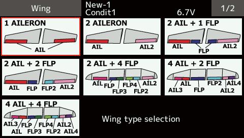
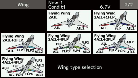
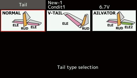
45 MODEL BASIC SETTING PROCEDURE Initial setting assigns 1 model to the T16SZ transmitter. The Model Select function is used to add models and to select models which are already set. The data for up to 30 models can be saved to the transmitter. Data can also be saved to the optional SD card. The currently selected model name is displayed at the Select the model type matched to the aircraft with the Model type select function of the Linkage menu. For an airplane, select the model type from among the 2 types: airplane and glider. After the wing type is selected the tail type select screen is displayed. Select the tail type matched to the aircraft. There are 13 wing types and 3 tail types for airplane and glider. the direction with the Reverse function of the Linkage menu. angle with the linkage, and fine tune them with the Sub trim and End point functions a limit position can also be set with the End point function. The End point function can movement, limit, and servo speed of each channel. Connect the ailerons, elevators, throttle, rudder, etc. in accordance with the model's instruction manual. For a description of the connection method, see the "Servos connection by model type". Note: The channel assignment of the T16SZ is different from that of our existing systems. Note that even for the same "airplane model", when the wing type and tail type are different, the channel assignment may be different. (The channel assigned to each function can be checked at the "Function" of the Linkage menu.) Throttle cut can be performed with one touch by a switch without changing the throttle trim position. Set throttle cut with the Throttle cut function of the Linkage menu. After activating the throttle cut function and selecting the switch, adjust the throttle position so that the carburetor becomes fully closed. For safety, the throttle cut function operates the throttle stick in the 1/3 or less (slow side) position.


46 The idling speed can be lowered with one touch by a switch without changing the throttle trim position. Perform this setting with the Idle down function of the Linkage menu. After activating the Idle down function and selecting the switch, adjust the idle down speed. For safety, the idle down function acts only when the throttle stick is slow side. *While the Throttle cut function is in operation, the Idle down function does not work. This function is used when an air brake is necessary when taking off or diving, etc. offset amount can be activated by a switch. The offset amount of the aileron, elevator, and flap servos can be adjusted as needed. Also the speed of the aileron, elevator, and flap servos can be adjusted. (In side/out side) A delay can be set for each condition, and a cut switch which will turn OFF the delay can be You can also set the auto mode, which will link Airbrake to a stick, switch, or dial. A separate stick switch or dial can also be set as the ON/OFF switch. AFR function is used to adjust the throw and operation curve of the stick, lever, and switch functions for each flight condition. This is normally used after End point The Condition select function automatically allocates the Condition 1 for each model. Condition 1 is the default condition and is the only one active when a new description of the Condition select function. *The Condition 1 is always on, and remains on until other conditions are activated by switches. *When a new condition is added, the model data of the Condition 1 is automatically copied to the new condition. *You can set the model data of new condition in the switch ON state. However, if the group mode (Gr) was selected in advance, the same data will be input at all the conditions. Select the single mode (Sngl) and adjust only the condition you want to change. For Group/Single mode switching, refer to the description at the back of this manual. *The Condition delay can be programmed for each channel. The Condition delay is used to change the servo throw smoothly when switching conditions.


47 match the fuselage used. Default setting assigns 1 model to the T16SZ. To add new models or to call a model already set, use the Model select function. per model. This is convenient when calling a model after registering the model names in advance. (The data of up to 30 models can be saved at the transmitter. Data can also be saved to the optional SD card.) The currently called model is displayed at the top of the screen. Before flying and before changing any If a different model type is already selected, select helicopter with the Model type function of the Linkage menu, and then select the swash type matched to the helicopter. *The Model type function automatically selects the functions for the chosen model type. Eight swash types are available for helicopters. *For a description of the swash type selection, refer to the Model type function. The Condition select function automatically allocates (General setting) Note: Delete conditions you have not set up and will not use. Otherwise you may cause a crash. *For a description of the condition deletion, refer to the Condition select function. The Normal condition is always on, and remains on until other conditions are activated by switches. The priority is throttle hold/idle up 2/idle up 1/normal. Throttle hold has the highest priority. Add other conditions, as required. The Condition delay can be programmed for each channel. The Condition delay is used to change the servo throw smoothly when switching conditions. when switch OFF) maneuvers.

 *If any interactions are noticed, for a description of the linkage correction function, please refer to the SWASH function.")
48 Connect the throttle rudder, aileron, elevator, pitch, and other servos in accordance with the kit instruction manual. For a description of the connection method, see "Servos connection by model type". Note: The channel assignment of the T16SZ is different from that of our existing systems. (The channel assigned to each function can be checked at the Function menu of the Linkage menu.) *If any interactions are noticed, for a description of the linkage correction function, please refer to the SWASH function. This function adjusts the throttle or pitch operation curve in relation to the movement of the throttle stick for each condition. incorrect, use the Reverse function of the (Gyro side function) carburetor can fully close at full trim throttle cut. and End point function (rudder angle position can also be set with the End point function. Call the throttle curve of each condition with the condition select switch. Normal curve creates a basic throttle curve together with the pitch curve (Normal) so that the easiest. The low side Throttle curve creates a curve The curve is not used when performing auto rotation dives. < Call the pitch curve of each condition with the condition select switch. º~6º. Set the pitch at hovering with the stick position at *Stability at hovering may be connected to the throttle curve. Adjustment is easy by using the hovering throttle function and hovering pitch function together. The idle up 1 pitch curve function creates a curve
 function is used to adjust the throw and operation curve of aileron, elevator and rudder for each condition.")

49 ºº as standard. The high side pitch setting is less than idle up 1. The standard is +8º. the high and low sides. ºº AFR (D/R) function is used to adjust the throw and operation curve of aileron, elevator and rudder for each condition. mentioned "Throttle/Pitch curve setting" *If throttle hold is necessary, please refer to the Throttle hold function. Throttle cut provides an easy way to stop the engine, by flipping a switch with the throttle stick at idle. The action is not functional at high throttle to avoid accidental dead sticks. The switch s location and direction must be chosen, as it defaults to INH. *With throttle stick at idle, adjust the cut position until the engine consistently shuts off, but throttle linkage is not binding. swash plate in the aileron (Left/Right Cyclic) and elevator (Forward/Aft Cyclic) direction corresponding to each operation of each condition. The gyro sensitivity and mode switching function is for each condition. maximum sensitivity minimum helicopter, this function may not have any effect at high gyro sensitivity. slowing caused when the swash plate operates at the same time as ailerons or elevator, please refer to the Throttle This mixing is used with engines that allow needle This mixing is dedicated governor mixing when a switched for each condition.
50 The T16SZ transmitter channels are automatically assigned for optimal combination according to the type selected with the Model type function of the Linkage menu. The channel assignment (initial setting) for each model type is shown below. Connect the receiver and servos to match the type used. *The set channels can be checked at the Function screen of the Linkage menu. The channel assignments can also be changed. For more information, read the description of the Function menu.
51
52
53 * Output channels differ by each system of a table. When using a system with few channels, there is a wing type which cannot be used. It cannot be used when there is a function
54
55
![SYSTEM MENU The System menu sets up functions of the transmitter. This does not set up any model data. [Display]: Display adjustment.](/docs-images/92/109992498/images/56-1.jpg "[Sound volume]: Adjust the volume of: Other sound, Warning, Voice [System timer]: Resets the system timer. [H/W setting]: Stick mode selection (Mode 1 - Mode 4 ).")
56 SYSTEM MENU The System menu sets up functions of the transmitter. This does not set up any model data. [Display]: Display adjustment. [Sound volume]: Adjust the volume of: Other sound, Warning, Voice [System timer]: Resets the system timer. [H/W setting]: Stick mode selection (Mode 1 - Mode 4 ). J1-J4 sticks correction can be performed. [Battery] Battery alarm voltage setting. Auto power off time setting. [Range check] The output of the transmitter is lowered, for Range checking. [S.Bus servo]: S.Bus servo setting. [Information]: Sets the User name, Language, and Unit system. Displays the program version, and SD card information.

57 The following LCD screen adjustments: Backlight max. brightness adjustment becomes darker. Backlight min. brightness adjustment becomes darker. *It cannot be made brighter than Backlighting brightness adjustment. Backlight decrease time *The backlight consumes a large amount of power. We recommend that you turn off the backlight by setting the backlight power-off time to about one minute. Touch calibration *In ordinary operation, this calibration is not necessary. If you notice the Touch Panel is not functioning correctly after long use, we recommend that you carry out this calibration.


58 This function can set the volume of "Other sound," "Warning," and "Voice," respectively. Sound volume Setting method *If you tap " ", the volume will increase. If you tap the " ", the volume will decrease. This function adjusts the system timer of the T16SZ transmitter. The system timer can also be reset. *The system timer is displayed on the Home screen. System timer reset


59 Usually, this H/W setting is unnecessary. Please perform this calibration only if a change at the center of a stick should arise after prolonged use. Stick mode Mode 1-4 can be chosen. But, it isn't changed until data is reset. To change the mode the stick ratchet must be changed. Request that this be done by Futaba Service. (Charged How to Calibrate doing the calibration. *Check after calibration to make sure that neutral is 0%, the bottom right side is +100%, and the top left side is -100%.

60 Select the battery alarm voltage according to the battery to be used. Auto power off time setting *When the time the transmitter is inactive reaches the set time, the power is turned off automatically. This time can be set up to 1 hour in 10 minutes increments. The auto power off function can also be deactivated. *An audible alarm is sounded from 3 minutes before auto power off. When a stick or switch is operated, the alarm is cleared. *When the low battery voltage setting is changed, it is changed for every model in the transmitter. A unique voltage cannot be set for each model. A change in the low battery voltage setting also does not reset other data. The 'range check mode' reduces the transmission range of the radio waves to allow for a ground range check. *The range check mode, when activated, will continue for 60 seconds unless the user exits this mode early. When the progress bar reaches 60 second mark, the RF transmission automatically returns to the normal operating power.
 servos, there are some functions which cannot be used.")
 * After reading completion, with connection of the above Procedure for changing S.BUS servo setting If you use multiple S.")
61 An S.BUS(2) servo can memorize the channel and various settings you input. Servo setting can be performed on the T16SZ screen by wiring the * With some S.BUS(2) servos, there are some functions which cannot be used. If a function cannot be used, the display screen will change. (Only the function which can be used by a servo is displayed.) * After reading completion, with connection of the above Procedure for changing S.BUS servo setting If you use multiple S.BUS servos, only the desired servo in the group can be set by entering the ID of 3-way hub or Y-harnesses
62 S.BUS Servo Description of each parameter's function ID *There are functions that can and cannot be performed according to the servo type. Displays the ID of the servo whose parameters are to be read. It cannot be changed. Channel Channel of the S.BUS system assigned to the servo. Always assign a channel before use. Reverse The direction in which the servo rotates can be changed. Soft Start Restricts operation in the specified direction the instant the power is turned on. By using this setting, the first initial movement when the power is turned on slowly moves the servo to the specified position. Stop Mode The state of the servo when the servo input signal is lost can be specified. The "Hold" mode setting holds the servo in its last commanded position even if using AM or FM system. Smoother This function changes smoothness of the servo operation relative to stick movement changes. Smooth setting is used for normal flight. Select the "OFF" mode when quick operation is necessary such as 3D. Neutral Offset The neutral position can be changed. When the neutral offset is large value, the servo's range of travel is restricted on one side. Speed Control Speeds can be matched by specifying the operating speed. The speed of multiple servos can be matched without being affected by motor fluctuations. This is effective for load torques below the maximum torque. However, note that the maximum speed will not exceed what the servo is capable of even if the servo's operating voltage is increased. Dead band The dead band angle at stopping can be specified. [Relationship between dead band set value and servo operation] Small Value Setting Dead band angle is small and the servo is immediately operated by a small signal change. Large Value Setting Dead band angle is large and the servo does not operate at small signal changes. (Note) If the dead band angle is too small, the servo will operate continuously and the current consumption will increase and the life of the servo will be shortened. Travel Adjust The left and right travels centered about the neutral position can be set independently. Boost The minimum current applied to the internal motor when starting the servo can be set. Since a small travel does not start the motor, it essentially feels like the dead band was expanded. The motor can be immediately started by adjusting the minimum current which can start the motor. [Relationship between boost set value and servo operation] Small Value Setting Motor reacts to a minute current and operation becomes smooth. Large Value Setting Initial response improves and output torque increases. However, if the torque is too large, operation will become rough.
63 Boost ON/OFF OFF : It is the boost ON at the time of low-speed operation.(in the case of usual) ON : It is always the boost ON.(When quick operation is hope) Damper The characteristic when the servo is stopped can be set. When smaller than the standard value, the characteristic becomes an overshoot characteristic. If the value is larger than the standard value, the brake is applied before the stop position. Especially, when a large load is applied, overshoot, etc. are suppressed by inertia and hunting may occur, depending on the conditions. If hunting (phenomena which cause the servo to oscillate) occurs even though the Dead Band, Stretcher, Boost and other parameters are suitable, adjust this parameter to a value larger than the initial value. [Relationship between damper set value and servo operation] Small Value Setting When you want to overshoot. Set so that hunting does not occur. Large Value Setting When you want to operate so that braking is not applied. However, it will feel like the servo response has worsened. (Note) If used in the hunting state, not only will the current consumption increase, but the life of the servo will also be shortened. Stretcher The servo hold characteristic can be set. The torque which attempts to return the servo to the target position when the current servo position has deviated from the target position can be adjusted. This is used when stopping hunting, etc., but the holding characteristic changes as shown below. [Relationship between stretcher and servo operation] Small Value Setting Servo holding force becomes weaker. Large Value Setting Servo holding force becomes stronger. (Note) When this parameter is large, the current consumption increases. Buzzer When a servo is powered up without a transmitter signal, a buzzer sounds. (When transmitter signal is lost, a buzzer sounds until the servo regains the signal. This is not unusual. The transmitter has been turned OFF ahead of a servo power supply The buzzer sound of about 1.25 Hz continues sounding as servo power supply end failure alarm. (Do not insert or remove the servo connector while the receiver power is ON. A buzzer may sound by incorrect recognition.) Buzzer sound is generated by vibrating the motor of a servo. Since current is consumed and a servo generates heat, please do not operate the number more than needed or do not continue sounding a buzzer for a long time.
 units.")

64 This function registers the T16SZ user name and the language displayed at proportional can be changed. Telemetry numerical values can be displayed in either metric or SAE (yard-pound) units. The Information screen displays the T16SZ system program version information, SD card (memory size, card free size) information. *If an SD card is not inserted, no memory card information will be displayed. 1/3 T16SZ transmitter can register user's name. How to register user's name
65 LINKAGE MENU The Linkage menu is made up of functions which perform model addition, model type selection, end point setting, and other model basic settings. [Servo monitor]: Displays the servo test and operation position [Model select]: Model addition, call, deletion, copy, model name setting [Model type]: Model type, wing type, tail type, swash type, selection [Servo reverse]: Servo direction reversal [End point]: Servo basic rate adjustment and limit setting [Servo speed]: Servo speed setting [Sub-trim]: Adjusts the neutral position of each servo [Function]: Channel assignment of each function can be changed [Fail safe]: Fail safe function and battery fail safe function setting [System type]: System mode selection, link of a transmitter and receiver, telemetry mode selection [Trim setting]: Control step amount and mode selection of the digital trim [Throttle cut]: Stops the engine safely and easily [Idle down]: Lowers the idle speed of the engine [Stick alarm]: Can be set so that an audible alarm sounds when the throttle stick reaches the set position. [Timer]: Timer setting [Function name]: Function name can be changed [Sensor]: Various telemetry sensors setting [Telemetry]: Displays various data sent from the receiver [Tele.setting]: Telemetry data log [Trainer]: Starts and sets the trainer system. [User menu setting]: Original menu making

66 This is used for testing servo movement. neutral position of a servo horn. In order to prevent any potential difficulties, the servo test function will be inoperable, or the Servo Test function is not operational if the mode.


67 This function is used to load the settings of the The settings may be selected from either the memories are available in the transmitter. The name of the model stored in the transmitter and the SD card may be changed. This can be very useful to tell different models settings apart. Each the model name always appears in the display screen. The Copy function is used to copy one set of model data into a second memory within the transmitter and the SD card. It may be used for getting a head-start on setting up models with make a backup copy of a model setup before any changes are made. Model addition *The added model is displayed in the model list. *When a model is added, a receiver link is required.
68 Model call Model deletion (The model currently selected cannot be deleted.)


69 Model name change Model copy *If there is no model with the same name in the copy destination, the name of the copied model is saved. If there is a model of the same name, a number is added at the end of the model name and the model is copied. You can change the name later. *Indication date : When the model data is copied, the creation date for the current model is recorded.

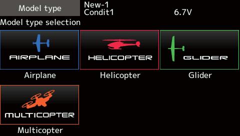
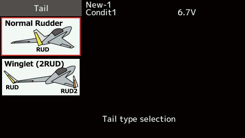
70 for airplanes. Eight swash types are available for helicopters. Seven types of main wings and three types of tail wings are available for gliders. model type are set in advance at the factory. Model type selection

71

72 Servo Reverse changes the direction of an movement. For CCPM helicopters, be sure to read the section on Swash AFR before reversing any servos. With CCPM helicopters, always complete your servo reversing prior to any other programming. control multiple servos, it may be confusing to tell whether the servo needs to be reversed or a setting in the function needs to be reversed. See the instructions for each specialized function for further details. Always check servo direction prior to every model memory, hook ups, and radio function. Servo reversing procedure After setting up a new model, be sure to are plugged into the proper receiver channels. channels by moving each stick and observing the
73 The End point function adjusts the left and right servo throws, generates differential throws, and will correct improper linkage settings. Servo travel adjustment Limit point adjustment
74 The Servo speed setting is used to set the servo delay for each channel, from channel l to channel to slow down servo position changes. The Servo channel. Servo speed setting The Sub-Trim function is used to set the servo neutral position, and may be used to make fine adjustments to the control surface after linkages and pushrods are hooked up. When you begin to set up a model, be sure that the digital trims are set to their center position. Sub-trim adjustment *See above


75 you will find that the optimized combinations of servo output channels and functions have been already preset. If you would like, on the functionsetting screen of the linkage menu, you can freely change combinations of servo output channels, multiple servo output channels such as assigning DG1, DG2 (switch channels) between servo output channels and input controllers Channel restrictions by a System Type Function change Operation control change *The same control can be assigned to multiple channels.

76 Trim change H/W reverse This function reverses the operation signal of the sticks, switches, trim levers, and knobs. signal, but does not change the display of the long as there is no special reason to use the reverse mode.

77 The Fail safe function is used to set up positions that the servos will move to in the case of radio lost and when receiver battery voltage becomes low. You may set either of two positions for each commanded position, or fail safe, where each servo moves to a predetermined position. You may choose either mode for each channel. an advanced battery monitoring function that warns you when the receiver battery has only a little power remaining. In this case, each servo is Do not continue to fly. Land as soon as possible. Remember, if the predefined control suddenly moves to a position you did not command, land at once and check your receiver battery. Defines servo position when signals are lost and when receiver battery voltage becomes low. Fail safe setting procedure Decide which channels you want to go to preset positions, and which ones you want to maintain their last commanded position. To select the fail safe mode you wish to set, use the F/S button. This F/S mode setting: the [F/S] button again. Battery fail safe setting procedure Each time the button is tapped, it toggles between B.F/S setting: button again. Battery Fail safe release function This function releases the predefined control from its held position after indicating that your receiver battery is low.
 Two receivers are recognized individually by ID setting function is used, by setting the first as as Two sets of receivers can be used as a set in the")
78 System Type selection *If you change the System type, other model data is not reset. *After any change, remember to test the model and fully check servo direction and motion. Dual receiver function (only FASSTest 18CH ) Two receivers are recognized individually by ID setting function is used, by setting the first as as Two sets of receivers can be used as a set in the voltage can be set to each receiver. receiver. Receiver linking transmitter it is linked to. When using a receiver other than one purchased as a set, linking is necessary. Moreover, a re-link is required when a new model is added by model selection, and at the time of system type change. Linking method Telemetry function (FASSTest /T-FHSS mode only) To use the telemetry function, set Telemetry to ACT. DL Interval (FASSTest/T-FHSS mode only) When a telemetry function is enabled, the data can be changed. If a DL interval is increased, the response of the sensor data display becomes slower, but stick response will improve. Battery fail-safe voltage setup (FASSTest / T-FHSS mode only) The voltage at which battery fail-safe activates memorizes the setting as it was at link. Since power consumption varies with battery type, servos and condition, please select the failsafe activation voltage for your own model.
79 The example for choosing System Type R7008SB R7003SB R7014SB R7018SB R7006SB R7008SB R7003SB R7014SB R7018SB R7006SB R608FS R6008HS R6108SB R6208SB R6014HS R6014FS R6203SB R6203SBE R6202SBW R6303SB R6303SBE R7014SB R7018SB R7006SB R617FS R6004FF R616FFM R6106HF R6106HFC R6203SB R6203SBE R6202SBW R6303SB R6303SBE R7006SB R3006SB R3008SB R3001SB *R3106GF R2006GS R2106GF R2008SB R2001SB ( Analog servos cannot be used with the R7008SB in the FASSTest 12CH mode.

80 This function adjusts the digital trim's control When the flight conditions are set, the trim operation can be coupled with any of the conditions selected through combination mode. Control step amount setting *When the value is made large, the change per step becomes larger. Separate/combination mode selection [Comb.] [Separ.]
81 Throttle cut provides an easy way to stop the idle. The action is not functional at high throttle to and direction must be chosen, as it defaults to ". Throttle cut setting procedure *With throttle stick at idle, adjust the rate until the engine consistently shuts off.


82 The Idle down function lowers the engine's idle The action is not functional at high throttle to avoid direction must be chosen, as it defaults to ". Idle down setting procedure

83 This function limits the travel of the swash plate to prevent linkage damage as the aileron and setting. Swash ring setting procedure *The movement area monitor shows the current aileron and elevator values and limit ranges by the yellow circle. *The swash movement is limited within the circle.


84 Neutral Point At your linkages, if the servo horn deviates from a perpendicular position at neutral, the linkage compensation functions in this menu may not compensate effectively. To correct this use the neutral point function. This will move the neutral point of the servos to the actual perpendicular menu, and does not affect the neutral position of other functions. Swash AFR Swash AFR function reduces/increases/reverses collective pitch functions, by adjusting or reversing the motion of all servos involved in that function, only when using that function. Mixing Rate the tendency of the swash-plate for each control. PIT to AIL, PIT to ELE, AIL to PIT, ELE to AIL, plate to operate correctly for each control using the Linkage Compensation tendency of the swash-plate for pitch control at low pitch and high pitch. Speed Compensation This function is used to cancel the reaction that is generated by the difference of the operation amount of each servo when the swash-plate moves.
85 Neutral point setting procedure *Adjusting the servo horn so that the neutral point position is *The neutral point is displayed on the screen. Swash AFR setting procedure Mixing rate setting procedure *A little adjustment using sub trim should be OK. *Adjust so that pitch operation when the pitch curve *Adjust the left and right sides separately. *Adjust the up and down sides separately. *Adjust the slow and high sides separately. Linkage correction setting procedure rate. *This function compensates for elevator interference by aileron operation or aileron interference by *The left and right sides can be adjusted separately. *If the interference increases when the compensation amount is increased, make the compensation direction "-". Speed compensation setting procedure Notes:
86

87 The Timer function may be set for any desired time, i.e. engine run time, specified times for competitions, etc. Two independent timers are provided for your use. The timers are stored independently with each model, meaning that when you switch between model setups, the timer associated with the new model is brought up automatically. The timers may be set to start and stop from the motion of any switch or stick. freely. Each timer has a capacity of up to Each timer may be set for count-down or count up operation with a target time. If a target time is set and the timer reaches the set time, a buzzer sound for each count is generated. Up timer/down timer selection Start/Stop/Reset switch setting
88 of the throttle stick. When the throttle stick is raised for faster speed, the speed of the timer usually throttle is positioned at low end, the timer's progress stops. It's possible to set it in the time which

89 Function name change method
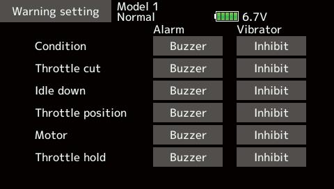
90 This screen displays and sets the various information from the receiver. An alarm and vibration can be in the aircraft can be reported by an alarm.

91

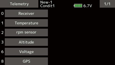
92 This screen registers the telemetry sensors used with the transmitter. When only one of a certain type of sensor is used, this setting is unnecessary and the sensor can be used by simply connecting it sensor, they must be registered here. [What is a slot?] sensors are classified in units called slot. There are slots from No. 1 to No. 31. Altitude sensors, GPS sensors and other data sensor units may use multiple slots. When using a sensor which uses two or more slots, the required number of slots is automatically assigned by setting up a start slot. the sensors themselves must allocate unused slots and memorize that slot. *Depending on the type of sensor, the slot numbers that can be allocated may be limited. Sensor The required number of slots The number which can be used as a start slot TEMP (SBS-01T/TE) 1 slot 1-31 RPM (SBS01RM/RO/RB) 1 slot 1-31 Voltage (SBS-01V) 2 slots 1,2,3,4,5,6,8,9,10,11,12,13,14,16,17,18,19, 20,21,22,24,25,26,27,28,29,30 Altitude (SBS-01/02A) 3 slots 1,2,3,4,5,8,9,10,11,12,13,16,17,18,19,20,21, 24,25,26,27,28,29 Current (SBS-01C) 3 slots 1,2,3,4,5,8,9,10,11,12,13,16,17,18,19,20,21, 24,25,26,27,28,29 S.BUS Servo sennsor 1,2,8,9,10,16,17,18, 6 slots SBS-01S) 24,25,26 GPS(SBS-01/02G) 8 slots 8,16,24 TEMP125-F slot 1-31 VARIO-F slots 1,2,3,4,5,6,8,9,10,11,12,13,14,16,17,18,19, 20,21,22,24,25,26,27,28,29,30 VARIO-F slots 1,2,3,4,5,6,8,9,10,11,12,13,14,16,17,18,19, 20,21,22,24,25,26,27,28,29,30 CURR-F slots 1,2,3,4,5,8,9,10,11,12,13,16,17,18,19,20,21, 24,25,26,27,28,29 GPS-F slots 8,16,24 Kontronik ESC 8 slots 8,16,24 Castle TL0 8 slots 8,16,24 JetCat V10 14 slots 1,2,3,4,5,6,7,8,9,10,11,12,13,14,15,16,17, 18 PowerBox 16 slots 8,16 Selling area Global Europe
93 When using multiple sensors of the same type the sensors must be registered in the transmitter. the following procedure. The ID of each sensor is registered in the transmitter. Reading all the sensors to be used *It is not necessary to carry out multiple battery connections like This function registers an additional sensor. Connect the sensor as shown in the figure at the right and register it by the following procedure. The sensor ID is registered in the transmitter. Additional sensor registration *When the number of slots needed in registration is insufficient, an error is displayed and registration cannot be performed. Disable unused slots or perform the following reload.


94 This procedure changes the slot number of one registered sensor. sensor is changed, the sensor cannot be used. Sensor slot change

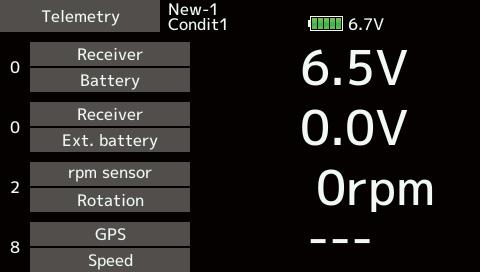
95 This screen displays your choice of data from the receiver. Also warnings can be activated regarding the Display Sensors Default display sensors can only be used by connecting the sensors to the receiver. For display of other sensors or to use the same type of sensor in multiple cases, either register them via the "Sensor" option on the Linkage menu or allocate the sensors to empty slots to have them display on the Telemetry pages for how to do this.
96 In this screen, the battery voltage of a receiver is displayed. If it becomes higher or lower than the settin, an alarm and/or vibration will alert you. *Only receiver voltage and EXT voltage can be used in functions. Alarm set *When the screen is tapped for one second, the rate is reset to the initial value.
97 The EXT-VOLT screen will display the data from In order to use this function, it is necessary to voltage of the EXT-battery. You will be alerted by an alarm or vibration if *Only receiver voltage and EXT voltage can be used in functions. Alarm set *When the screen is tapped for one second, the rate is reset to the initial value.
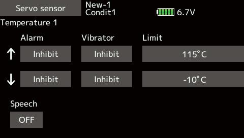
98 Temperature is a screen which displays/sets up the temperature information from an optional temperature sensor. If it becomes higher or lower than the setting, an alarm and/or vibration will alert you. *Only receiver voltage and EXT voltage can be used in functions. Alert set : Temperature warning *When the screen is tapped for one second, the rate is reset to the initial value.
99 The RPM Sensor screen is used to set up an optional rpm sensor and display the rotation information it transmits. If it becomes higher or lower than the setting, an alarm and/or vibration will alert you. *Only receiver voltage and EXT voltage can be used in functions. Alarm set : Over Under rotations *When the screen is tapped for one second, the rate is reset to the initial value.
100 Altitude is a screen which displays / sets up the altitude alarm. Warning by vibration can also be chosen. Data when altitude which changed from there. Even if the altitude of an from an airfield is displayed. This sensor calculates the altitude from atmospheric pressure. Atmospheric pressure will get lower as you go up in altitude. Using this, the sensor will estimate the altitude. Please understand that an pressure changes in a weather situation. *Only receiver voltage and EXT voltage can be used in functions. First, the set of a reference is required. *Atmospheric pressure is changed according to the weather Alarm set : Altitude *When the screen is tapped for one second, the rate is reset to the initial value.
101 VARIO is a screen which displays / sets up the variometer information from an optional altitude be known. If it becomes higher or lower than the setting, an alarm and/or vibration will alert you. To ensure that the pilot is aware as to the model's for ascent and descent. Additionally, depending upon the rate of climb or descent, the tones vary to indicate whether or not the airplane is climbing or descending at a rapid rate. *Only receiver voltage and EXT voltage can be used in functions. First, the set of a reference is required. *Atmospheric pressure is changed according to the weather Alert set : variometer *When the screen is tapped for one second, the rate is reset to the initial value.
102 Vario Melody Setting Tap the [Set] button *These settings can be made for each sensor. Next page Setting range Initial value Setting range Initial value Setting range Initial value Setting range Initial value Setting range Initial value


103 Setting range Initial value *This parameter is effective to all variometers.
104 In this screen, the battery voltage is displayed. In order to use this function, it is necessary to battery connected to two lines is displayed on EXT- lines is displayed here. In this screen, the battery voltage of a receiver is displayed. If it becomes higher or lower than the settin, an alarm and/or vibration will alert you. *Only receiver voltage and EXT voltage can be used in functions. Alarm set *When the screen is tapped for one second, the rate is reset to the initial value. EXT Line Normal Line EXT Line Normal Line wiring.
105 In this screen, the EXT battery voltage is displayed. In order to use this function, it is battery connected to two lines is displayed on EXT- VOLT. *Only receiver voltage and EXT voltage can be used in functions. Alarm set *When the screen is tapped for one second, the rate is reset to the initial value.
106 The Distance screen displays and sets altitude aircraft to be read by the transmitter. When the aircraft flies inside or outside the set distance, an alarm and vibration alerts the pilot. and connect the sensor in accordance with the sensor instruction manual. *Only receiver voltage and EXT voltage can be used in functions.
107 First, the set of a reference is required. Setting a "too far" alarm distance *When the screen is tapped for one second, the rate is reset to the initial value. Setting a "too close" alarm distance *When the screen is tapped for one second, the rate is reset to the initial value. *Positioning time of GPS take several minutes. Please do not move the model during this process. During acquisition, after the satellite's signals have been acquired, signal strength display on the transmitter will show three bars. Moving the model before the satellites are fully acquired will cause a delay in acquiring the satellite signal.
108 The speed screen displays and sets the speed data from an air speed. Consequently, with a head wind, the displayed speed decreases and with a tail wind, the displayed speed increases. and connect the sensor in accordance with the sensor instruction manual. *Only receiver voltage and EXT voltage can be used in functions. Alarm setting when speed increases *When the screen is tapped for one second, the rate is reset to the initial value. *Speed alarm precaution

109 The Altitude, Variometer, Position screen and connect the sensor in accordance with the sensor instruction manual. *Only receiver voltage and EXT voltage can be used in functions.
110 in-flight current, operating angle, and internal If you forget to connect the servo wiring during fuselage assembly, or the servo was disconnected, an alarm can be activated at the transmitter.
111

112 drive battery all at the same time.
113 Set the speech interval of telemetry data, and the logging of telemetry data to an SD card at chosen intervals. Telemetry data can be checked on your PC after Telemetry data has been adapted to the log function which is recorded at the SD card. Open the linkage menu Tele. setting screen. Log recording can be started and stopped by operating a switch. The Logging switch is selected. The log output interval can be set. * The data to be recorded is updated at the time set by Linkage menu System Type screen D/L interval. For example, when the log output interval is 1 second and the D/L interval is 2 seconds the same data is overlapped and recorded twice. Insert the SD card into the card slot. Set the switch set by Log Start/Stop Switch to ON. A beep sounds and a log file is created and recording of the telemetry data begins. Set the switch set by Logging switch to OFF. A beeping sound is generated and recording of the telemetry data stops. Turn off the transmitter power and remove the SD card. Log file A log file is created in the SD card LOG folder. Two files with the same filename, but a different extension are created. (Example: FLI, FLD) Extension FLI: Slot allocation information file Extension FLD: Log data file *When copying or moving a log file, always select both the.fli file and.fld file. Log files can be converted to CSV format by using the telemetry log converter available at the Futaba website. Notes Altimeter altitude data and GPS distance and altitude data output with the point that time logging started as the reference (0m). When the transmitter preset position and the log start position are different, the transmitter display and the log data display will also be different. The altitude and distance from the take-off position can be recorded by starting logging immediately after take-off. The transmitter gear ratio or number of fins setting is not reflected in the speedometer log data (speed). Multiply the gear ratio or number of fins by the speed data. When the SD card becomes full, recording stops and does not resume even if logging is restarted.
")
114 The repeat time and duration time for the telemetry alarm (buzzer, vibration and speech) can be set.
115 instructor to choose which channels and operation modes can be used in the student's transmitter. The function and rate of each channel can be set. The training method can also be matched to the student's skill level. Two transmitters must be connected by an optional Trainer Cord, and the Instructor's transmitter should be programmed for trainer operation, as described below. When the Instructor activates the trainer switch, When the switch is released the Instructor regains control. This is very useful if the student gets the aircraft into an undesirable situation. Note: This trainer system can be used in the following manner: transmitter, if the channel order is different, it is necessary to match the channel order before using this function. You can select the channel of input data from student's PPM. the instructor's transmitter which requires the student's from the trainer jack. Corresponding types of transmitters and trainer mode settings:

116 When using at the student side *When changing the mode, tap to the item you want to the mode. When using at the teacher side *When changing the mode, tap to the item you want to the mode. item, call the switch setup screen and set the desired switch *The switch mode can also be selected when setting the [Alternate] is selected, the trainer function is alternately turned on and off each time the switch is operated. This
117 Trainer student channel setting function In training mode, the instructor's transmitter can pick up the student's signal on both the "Function" two transmitters to connect even if the student and instructor have set up their transmitters differently. the signal of the same channel of the student's transmitter is *The setting above allows setting of the servo throw relative to the amount of student side operation when [MIX] or *When the value is tapped, the rate is reset to the initial value. *When setting the switch at each channel, tap to the "SW" item of the channel you want to change, call the switch setup screen, and select the switch.
118

119 System, Linkage, and Model. Also, you can create a personalized User menu that can include all of the menus that you use most often. *Any change made to data entered from the User menu or from the normal method of use are the same. Changes made in either way are saved into the transmitter memory. How to call a User menu
: Reset the digital trim setting.")
120 This function is designed to allow you to reset selected portions or all of the settings saved in the active model memory. You may individually choose to reset the following sets of data: Trim (All condition): Reset the digital trim setting. *All the conditions, or the condition currently being displayed *The trim step amount and trim rate are not reset. Trim (Current and Group condition): Reset the digital trim setting. *Current condition, group condition, can be selected. *The trim step amount and trim rate are not reset. Model menu setting: Resets all the functions in the Model menu All model setting: Resets all Linkage and Model menu functions Function Name: A function name is reset. Telemetry: Reset the telemetry setting. Data resetting method
121 MODEL MENU (Common functions) This section describes the AFR, program mixing, and other functions common to all model types. Before setting the model data, use the Model Type function of the Linkage menu to select the model type matched to the fuselage. When another model type is selected thereafter, the AFR, program mixing, and other setting data are reset. The functions in the Model menu can be set for each flight condition. When you want to use the system by switching the settings for each condition by switch, stick position, etc., use the Condition Select function to add flight conditions. (Up to 8 conditions can be used) Note: The T16SZ is designed so that the airplane and glider model types are compatible with aircraft of similar type wings. This section outlines the relationship between the functions common to airplanes and gliders, except some dedicated functions, and model type. The setting items depend on the number of servos and other differences according to the wing type used, but reread them. The setup screens in the instruction manual are typical examples. name and return to the Home screen. Program.mixes (Model menu screen example) *The Model menu screen depends on the model type. [Servo monitor]: Displays the servo test and operation position [Condition select]: Flight conditions addition, deletion, copy, condition renaming, and condition delay can be set. [AFR]: Sets the angle and curve of all the operation functions. [Dual rate]: D/R curve which can be switched with a switch, etc. can also be added. [Program. mixes]: Program mixing which can be freely customized. Up to 10 mixes can be used for each condition.
122 Flight condition's addition, deletion, copy, condition renaming, and condition delay can be set. [All model types] The functions in the Model menu can be used by switching the settings of up to 8 flight conditions conditions. Add conditions, as required. When you do not want to use the Condition select function, this setting is unnecessary. In this case, use the flight conditions assigned at initial setting. addition to ordinary toggle switch, is possible as the flight condition selector switch, this Unnecessary fuselage motion generated when there are sudden changes in the servo positions and when there are variations in the operating time between channels during condition switching can be suppressed. The delay can be set for each channel. When setting the delay function at the switching destination condition, the related function changes after a delay corresponding to the set amount. operation priority can be freely changed. selected condition name is displayed on the screen. When a condition has been added, give it a name which can be easily call the setup screen shown below. 1. Select the condition by tapping the condition you List. 2. Tap the [Rename] button. 3. Enter the new name from the the screen. name is registered. 1. When the [Add] button is tapped, the *Only the number of buttons corresponding to the conditions which can be added are displayed. 2. Select the desired conditions by tapping the buttons. *The selected conditions are added to Conditions List. 3. Tap the [--] button to call the <Switch> screen. 4. Select the switch to be used in condition switching. (See "Switch selection method" at the end of this manual for selection method details.) conditions is copied.
 1. Select the condition by tapping the condition you List. 2. Tap the [Remove] button. 3.")
123 appears. 2. Select the condition by tapping the button of the copy source conditions. 3. Next, select the condition by tapping the copy destination condition. 5. When the [Yes] button is tapped, the data is copied. (To abort copying, tap the [No] button.) 1. Select the condition by tapping the condition you List. 2. Tap the [Remove] button. 3. When the [Yes] button is tapped, the condition is reset. (To abort resetting, tap the [No] button.) 1. Tap the condition whose priority you want to change priority [ ] or [ ] button. (The last condition has the highest priority.) *The initial setting condition cannot be moved. It has the lowest priority. 1. Switch to the condition you want to set. want to set. 3. Use the value input buttons to set the delay.
![The angle and curve of each operation function can be set. [All model types] AFR function is used to adjust the throw and operation curve of the stick, lever, and switch the maximum throw.](/docs-images/92/109992498/images/124-1.jpg "When mixing is applied from one channel to another channel, both channels can be adjusted at the same time by adjusting the operation rate through the AFR function.")
124 The angle and curve of each operation function can be set. [All model types] AFR function is used to adjust the throw and operation curve of the stick, lever, and switch the maximum throw. When mixing is applied from one channel to another channel, both channels can be adjusted at the same time by adjusting the operation rate through the AFR function. of curves (EXP1, EXP2, and Point) can be used for the point curve type. (Initial setting: 9 points) The number of points can also be increased and decreased and curves from complex curves to simple curves can be used. speed of each function when the function is operated (including at flight condition operates smoothly at a constant speed corresponding to the set speed. the setup screen shown below. 1. When the function select button is tapped, a selection screen appears. 2. Select the function you want to set at the selection screen.

125 D/R curves which can be switched by switch, etc. can be added. The curve can be adjusted by the AFR function. condition. call the setup screen shown below.


126 mixings can be used for each condition. [All model types] Programmable mixing may be used to correct undesired tendencies of the aircraft, and it may also means that the motion of a command channel, called the "master," is added to the motion of the mixed channel, called "slave." You may choose to have the Masters trim added to the Slave channel response, if you desire ("Trim" setting). The mixing curve can be changed so that the undesired tendencies can be corrected effectively by setting the EXP1/EXP2/Point modes. Offset-type mixing applies a fixed offset or preset to the programmed channel servo operation and may control up to four circuits simultaneously. The Programmable mixing includes a powerful link function, which allows Programmable mixing to be linked with the special mixing functions, or with other programmable mixing functions. The link function can be set up for Master and Slave channel individually. the setup screen shown below.
127 Activating functions for only the selected conditions: mode. *Each time the button is tapped, it toggles between the Gr and Sngl modes. Using the offset mode: *Each time the button is tapped, it toggles between the Mixing and Offset modes. 1. Tap the button of the mixing you want to set. The mixing setup screen is displayed. Activate the function. 2. Activate the function by tapping the [INH] button. *Each time this button is tapped, it toggles between [INH] and [ON/OFF]. direction switching *An ON/OFF switch is not set even when the function is activated. switch, tap the [--] button to call the <Switch> direction. *For a description of the selection method, see [Switch setting method] at the back of this manual. mixing) menu and select the master channel. *Each time the button is tapped, it toggles between mixing direction + and - and "OFF" (no link). *Master channel control can be set to stick, VR, and other simple travels which do not include End point, AFR, D/R, mixing setting, etc. In this case, display the <Function,H/ W> screen by tapping the [Stick, Switch, Dial] button and then select master channel side control. 1. Tap the Slave button to call the Function menu and select the slave channel. *Each time the button is pressed, it toggles between mixing direction + and - and "OFF" (no link). button on the screen. *When mixing includes master side trim, set the Trim button to [ON]. When mixing does not include master side trim, set the Trim button to [OFF]. *Each time this button is pressed, it toggles between [ON] and [OFF]. *This is effective when the master channel is set by Function. 1. Tap the curve type selection button of the curve type you want to use to display the selection screen. Then, select the curve you want to use. *For a description of the curve setting method, see the description at the back of this manual. 1. When using the curve fine tuning function, tap the [--] button of the Fine Tuning item to call the <Switch> screen and then select the lever, VR, etc. you want to use. the description at the back of this manual. 1. When setting the servo speed, tap the speed button. The Servo speed setup screen is displayed. *For a description of the servo speed setting method, see the description at the back of this manual. *Offset mixing changes the speed. Use the Speed In and Speed Out buttons to readjust the speed. The mixing switch can set a delay with a different rate at starting and stopping. *This function is inactive when a mixing switch is not set.
128 MODEL MENU (Airplane/Glider/Multicopter functions) The dedicated mixes, etc. usable when airplane or glider model type is selected are displayed in this Model menu functions section. First use the Model type function of the Linkage menu to preset the model type, wing type, and tail type matched to the fuselage used. Other settings reset the data used in mixing function, etc. These dedicated mixes can be set for each flight condition, as required. When you want to use the system by switching the settings for each condition by switch or stick position, use the (Up to 8 conditions can be used) Note: The T16SZ is designed so that the airplane and glider model types can handle aircraft of the same wing type. The functions common to airplanes and gliders, except some dedicated functions, are summarized without regard to the model type. The setting items are different, depending on the number of servos, etc. according to the wing type used. The setup screens in the instruction manual are typical examples. name and return to the Home screen. Aileron differential This function adjusts the left and right ailerons. possible. This is convenient when making settings [Airplane/glider, 2 ailerons or more] Flap setting The flaps can be adjusted independently. For a 4 flaps model, the camber flaps can be mixed with the AIL This mix operates the camber flaps in the aileron mode. It improves the operation characteristic of the (Model menu screen example) *The Model menu screen depends on the model type. This mix operates the brake flaps in the aileron mode. It improves the operation characteristic of the This mix is used when you want to operate the rudder at aileron operation. Banking at a shallow bank angle is possible. [Airplane/glider, general] This mix is used when you want to the mix camber flaps with elevator operation. Lifting force can be increased at elevators up. [Airplane/glider, 2 ailerons or more]
129 Camber mixing This mix adjusts the camber and corrects the elevators. [Airplane/glider, 2 ailerons or more] This mix is used to correct operation of the airbrakes (spoilers) when landing. [Airplane/glider, general] This mix is used to correct for attitude changes when the camber flaps are being used. [Airplane/glider, 2 This function is used to correct roll knife edge, etc. of stunt planes. [Airplane/glider, general] This function is used to correct roll maneuvers, knife edge, etc. of stunt planes. [Airplane, general] This function is used when powerful brake operation is necessary. [Glider, 2 ailerons or more] Trim mix 1/2 The ailerons, elevators, and flaps trim offset rate can be called by switch or condition selection. [Glider general] Snap roll This function selects the snap roll switch and adjusts the steering angle of each rudder. Servo speed can also be adjusted. [Airplane general] This function is used when airbrakes are necessary when landing or when diving, etc. during flight. [Airplane, general] This is a dedicated mix when a GYA Series gyro is used. [Airplane/glider/multicopter, general] Ailevator This function adjusts the elevators and ailerons of models with elevator specifications. [Airplane/glider, Acceleration Allows a brief "overload" in response to sudden general] Motor The operation speed when the motor of F5B and other EP gliders is started by switch can be set. [Airplane/glider, general] V-Tail This function adjusts the elevators and rudder of Winglet This function adjusts the left and right rudders of
![[Airplane/glider, 2 ailerons or more] The left and right aileron differential can be adjusted independently.](/docs-images/92/109992498/images/130-0.jpg "The differential rate can also be adjusted according to the flying state by menu and call the setup screen shown below. Aileron differential *The display screen is an example.")
130 [Airplane/glider, 2 ailerons or more] The left and right aileron differential can be adjusted independently. The differential rate can also be adjusted according to the flying state by menu and call the setup screen shown below. Aileron differential *The display screen is an example. The actual screen depends on the Model Type. Aileron differential Setting method setting item. Adjust the aileron angles. item and tap the screen to call the selection
![[Corresponding model type]: Airplane/ The up/down travel of each flap (camber flaps: FLP1/2, brake](/docs-images/92/109992498/images/131-0.jpg "flaps: FLP3/4) can be adjusted independently at each servo according to the wing type.")

131 [Corresponding model type]: Airplane/ The up/down travel of each flap (camber flaps: FLP1/2, brake flaps: FLP3/4) can be adjusted independently at each servo according to the wing type. offset call the setup screen shown below. Setting method the wing type. Adjust the travel independently. the reference point. the switch and tap the screen to call the selection screen. Then, select the switch and
![[Corresponding model type]: Airplane/ This mix operates the camber flaps (FLP1/2) in the aileron mode.](/docs-images/92/109992498/images/132-0.jpg "When the aileron stick is manipulated, the ailerons and camber flaps perform aileron operation simultaneously and the operation")

132 [Corresponding model type]: Airplane/ This mix operates the camber flaps (FLP1/2) in the aileron mode. When the aileron stick is manipulated, the ailerons and camber flaps perform aileron operation simultaneously and the operation characteristic of the roll axis is improved. model menu and call the setup screen shown below. AIL AIL Setting method the switch and tap the screen to call the selection screen, and then select the switch Adjust the mixing rate. *When the mixing direction is reversed by the linkage, adjustments can be made by changing the mixing rate
133 [Corresponding model type]: Airplane/ This mix operates the brake flaps (FLP3/4) in the aileron mode. When the aileron stick is manipulated, the aileron and brake flaps perform the aileron operation simultaneously and the operation characteristic of the roll axis is improved. menu and call the setup screen shown below. AIL AIL of the switch and tap the screen to call the selection screen, and then select the switch Adjust the mixing rate. *When the mixing direction is reversed by the linkage, adjustments can be made by reversing the mixing rate
134 [Corresponding model type]: Airplane/glider, general Use this mix when you want to mix the rudders with aileron operation. model menu and call the setup screen shown below. Aileron Rudder Aileron Rudder Setting method of the switch and tap the screen to call the selection screen, and then select the switch mode can also be selected. increases and decreases, respectively. increases. increases. right of the neutral position, the mixing rate increases.
![[Corresponding model type]: Airplane/glider, 2 ailerons or more This function is used when you want to mix the be increased. menu and call the setup screen shown below.](/docs-images/92/109992498/images/135-0.jpg "Elevator Camber Elevator Camber Elevator Camber Setting method the switch and tap the screen to call the selection screen, and then select the switch adjustment rate can be set.")
135 [Corresponding model type]: Airplane/glider, 2 ailerons or more This function is used when you want to mix the be increased. menu and call the setup screen shown below. Elevator Camber Elevator Camber Elevator Camber Setting method the switch and tap the screen to call the selection screen, and then select the switch adjustment rate can be set. selected.


136 This function adjusts the rate of camber operation which operates the wing camber (ailerons, camber flaps, brake flaps) in the negative and positive directions. The aileron, flap, and elevator rates can also be adjusted independently by curve, and attitude changes caused by camber operation can be corrected. *Initial setting assigns camber operation to side lever LS. menu and call the setup screen shown below. [Corresponding model type]: Airplane/glider, 2 ailerons or more adjustments can be made by changing the be set.
137 Setting method of the switch and tap the screen to call the selection screen, and then select the switch [Condition delay] item. Set the delay. the aileron, flap, and elevator curve/rate screens. The rate and curve of each servo can be set the curve setting method, see the description The servo speed can also be adjusted. and tap the screen to call the selection screen, and then select the switch and set its
138 [Corresponding model type]: Airplane/glider, general This mix is used when you want to mix the elevators with airbrake (spoiler) operation. It raises the elevators to correct for dropping of the nose during airbrake operation. *This function does not operate when airbrake is not assigned at the Function menu in the Linkage menu. elevator servos can be adjusted. menu and call the setup screen shown below. *The display screen is an example. The actual screen depends on the model type. Setting method the switch and tap the screen to call the selection screen, and then select the switch this manual. mode can also be set.
![[Corresponding model type]: Airplane/ glider, This mixing is used to correct changes (elevator menu and call the setup screen shown below.](/docs-images/92/109992498/images/139-1.jpg "Camber flap ELE Camber flap ELE Setting method of the switch and tap the screen to call the selection screen.")
139 [Corresponding model type]: Airplane/ glider, This mixing is used to correct changes (elevator menu and call the setup screen shown below. Camber flap ELE Camber flap ELE Setting method of the switch and tap the screen to call the selection screen. Then, select the switch and *When the mixing direction is reversed by the linkage, adjustments can be made by changing the mixing rate polarity (+ or ). item and tap the screen to call the selection operation mode can be selected.
140 [Corresponding model type]: Airplane/glider, general This function is used when you want to mix the ailerons with rudder operation. It is used when rudder is applied during roll maneuvers, knife edge, etc. of acrobatic planes. It can be used to bank scale models, large models, etc. like a full size plane. and call the setup screen shown below. Setting method of the switch and tap the screen to call the selection screen. Then, select the switch and adjustment rate can be set.
![[Corresponding model type]: Airplane, general This function is used when you want to mix elevator operation with rudder operation.](/docs-images/92/109992498/images/141-1.jpg "It is used to correct undesirable tendencies when rudder is applied in roll maneuvers, knife edge, etc. of acrobatic planes. model menu and call the setup screen shown below.")
141 [Corresponding model type]: Airplane, general This function is used when you want to mix elevator operation with rudder operation. It is used to correct undesirable tendencies when rudder is applied in roll maneuvers, knife edge, etc. of acrobatic planes. model menu and call the setup screen shown below. Setting method of the switch and tap the screen to call the selection screen. Then, select the switch and adjustment rate can be set.
![[Corresponding model type]: Glider, 2 ailerons or more This function allows powerful brake operation by simultaneously raising the left and right ailerons and lowering the flaps (camber flap, This](/docs-images/92/109992498/images/142-0.jpg "setting will allow the ailerons to be raised while the flaps are simultaneously lowered. Butterfly (crow) produces an extremely efficient landing configuration by accomplishing the following: 1.")

142 [Corresponding model type]: Glider, 2 ailerons or more This function allows powerful brake operation by simultaneously raising the left and right ailerons and lowering the flaps (camber flap, This setting will allow the ailerons to be raised while the flaps are simultaneously lowered. Butterfly (crow) produces an extremely efficient landing configuration by accomplishing the following: 1. Slow the aircraft s velocity. the tendency to tip stall. 3. Create more lift toward the center of the item selected when operated to the position to reference point is offset too much, unexpected operation may be performed. also be set. *When servo binding occurs when setting the ailerons and rate. *The display screen is an example. The actual screen depends on the model type. menu and call the setup screen shown below.

143
144 [Corresponding model type]: Glider, general These functions call the ailerons, elevators, and The amount of ailerons, elevator, and flaps a switch. As an example Trim mix 1 can be set up for and a slight amount of up elevator. Trim mix 2 can be used for high speed flying, with both of down elevator. The trim functions can be activated during can be set to provide a smooth transition between the two. Trim mix 2 will have priority over Trim mix 1. menu and call the setup screen shown below. Example. Set the trim mix function to *When separating the settings for each condition, move to the [Group] item and set it to [Single]. 3. Select the [Manual] or [Auto] mode. <Speed> <Condition Delay> can be set for each condition. Condition delay operation can be interrupted and each rudder cut switch.
![[Corresponding model type]: Airplane, general This function selects the switch and rate adjustment of each rudder, (ailerons, elevators, or switch in the state in which the](/docs-images/92/109992498/images/145-0.jpg "direction switch was switched to the direction in which you want roll in each direction can be executed by means of independent switches.")

145 [Corresponding model type]: Airplane, general This function selects the switch and rate adjustment of each rudder, (ailerons, elevators, or switch in the state in which the direction switch was switched to the direction in which you want roll in each direction can be executed by means of independent switches. the switch can be set so that snap roll is not executed when, for instance, the landing gear is lowered, even if the switch is turned on accidentally. The snap roll switch is activated only *The snap roll up side left and right and down side left and right direction switches are selected here. The operation speed of each control be changed and snap roll executed by performed. and call the setup screen shown below.
 offset amount can be activated by a switch.")
 A delay can be set for each condition, and a Cut switch which will turn OFF the delay can be chosen.")
146 This function is used when an air brake is necessary when landing or diving, etc. The preset elevators and flaps (camber flap, brake flap) offset amount can be activated by a switch. The offset amount of the aileron, elevator, and flap servos can be adjusted as needed. Also the be adjusted. (In side/out side) A delay can be set for each condition, and a Cut switch which will turn OFF the delay can be chosen. Trim amounts set the Auto Mode, which will link Airbrake to a stick, switch, or dial. A separate stick switch or dial can also be set as the ON/OFF switch. setup screen shown below.
![[Corresponding model type]: Airplane/glider/multicopter, general This function is used when a GYA Series gyro is used to stabilize the aircraft's attitude.](/docs-images/92/109992498/images/147-0.jpg "The sensitivity and operation mode (Normal mode/gy mode) can be switched with a switch. switched. simultaneously controlled. *Initial setting does not assign a sensitivity channel.")
147 [Corresponding model type]: Airplane/glider/multicopter, general This function is used when a GYA Series gyro is used to stabilize the aircraft's attitude. The sensitivity and operation mode (Normal mode/gy mode) can be switched with a switch. switched. simultaneously controlled. *Initial setting does not assign a sensitivity channel. Use the Function menu of the Linkage menu to assign the sensitivity channel (Gyro/Gyro2/Gyro3) used to a vacant channel beforehand. call the setup screen shown below.
148 : at *Set so that Rate 1 is turned on at the back position of switch E and Rate 3 is turned ON at the front position. Since switch E is turned OFF at the center, Rate 2 remains [INH].
149 [Corresponding model type]: Airplane/glider, Tail type Ailevator (Effective only when 2 servos used at the elevators) This function improves the operating performance of the roll axis by operating the elevators as ailerons. Ailevator is where each elevator in a standard ailerons on a wing. In addition to each elevator side moving up and down together, each side moves in opposite directions when moving as an ailevator. as they can serve the same purpose. Typically, both ailevator and ailerons are coupled together to maximize roll performance, especially on larger wingspan planes. Note: Select ailevator as the Model type at the Model type screen. This changes the output menu and call the setup screen shown below. Tap to the item you want to adjust. buttons. *If the mixing direction is reversed by the linkage, adjustments can be made by changing the mixing rate moved at the same time, the controls may bind or run out of travel. Decrease the travel until no binding occurs.
![[Corresponding model type]: Glider, general Acceleration setting can be performed at Elevator, only) setting. The setting method is the same.](/docs-images/92/109992498/images/150-0.jpg "side and down side. menu and call the setup screen shown below. Setting method can be set.")
150 [Corresponding model type]: Glider, general Acceleration setting can be performed at Elevator, only) setting. The setting method is the same. side and down side. menu and call the setup screen shown below. Setting method can be set. operation point is exceeded, acceleration is performed.
![[Corresponding model type]: Airplane/glider, general This function lets you set the operation speed when the motor of an F5B or other EP glider is started by switch.](/docs-images/92/109992498/images/151-0.jpg "The operation speed can be set in 2 ranges of slow speed flight and high speed operated as a safety function by setting 2 switches. call the setup screen shown below.")
151 [Corresponding model type]: Airplane/glider, general This function lets you set the operation speed when the motor of an F5B or other EP glider is started by switch. The operation speed can be set in 2 ranges of slow speed flight and high speed operated as a safety function by setting 2 switches. call the setup screen shown below. A switch that turns the function itself direction of the motor switch is memorized. changes. screen. The speed 1 and speed 2 region boundary can be changed, The speed when speed 1 and speed 2 are Notes

152 This function lets you adjust for left and right rudder angle changes at elevator and rudder operation of a rudder movement as elevators. In addition to each rudder side moving up and down together, each side moves in opposite directions when moving as elevators. can serve the same purpose. the setup screen shown below. Tap to the item you want to adjust. buttons. *If the mixing direction is reversed by the linkage, adjustments can be made by changing the mixing rate moved at the same time, the controls may bind or run out of travel. Decrease the travel until no binding occurs.

153 This function adjusts the left and right rudder angles of airplanes with winglets. Winglets are used to improve the efficiency of wingtip vortices. The winglet is a vertical or angled extension at the tips of each wing. Winglets work by increasing the effective aspect ratio wing without adding greatly to the structural stress and hence necessary weight of its structure lowering of induced drag, though it would cause parasitic drag and would require boosting the would come a point at which no overall useful saving would be made. A winglet helps to solve this by effectively increasing the aspect ratio without adding to the span of the wing. call the setup screen shown below. Tap to the item you want to adjust. buttons. *If the mixing direction is reversed by the linkage, adjustments can be made by changing the mixing rate


154 MODEL MENU (Helicopter functions) This section contains information on the commands that apply to helicopters only. For instructions on airplane, glider and multicopter, refer to the sections pertaining to those aircraft. Use the Model type function in the Linkage menu to select the swash type matched to the fuselage beforehand. Also, add flight conditions at the Condition Select screen if necessary before setting the model data at each function. (Up to 8 conditions can be used) The AFR function, dual rate function and other functions common to all model types, are described in a separate section. When performing adjustments, such as idling up, when the engine is engaged, keep the throttle stable so as to prevent the engine from revving too high. Once your adjustments are complete, always make sure to set the function to [OFF]. *Condition hold ON/OFF operation is possible under normal conditions and the throttle stick is more than 1/3rd into the slow throttle range. Throttle servos will remain at the throttle stick position during ON operation. Under the conditions described above, tap the Condition hold [OFF] displayed on the screen. During function operation, Condition hold will display [ON] and an alarm will sound. Program.mixes (Model menu screen example) *The Model menu screen depends on the model type. Pitch curve: Pitch curve and hovering trim adjustment Throttle curve: Throttle curve and hovering trim adjustment Acceleration: Allows a brief "overload" in response to sudden throttle and pitch commands Throttle hold: Moves the throttle to idle during autorotation Swash mixing: Compensates for each control response Throttle mixing: Compensates for power loss when cyclic applied Handles torque changes from pitch angle inputs Gyro: Used to switch gyro sensitivity Governor: Used to switch RPM of the helicopter s head
155 This function adjusts the pitch operation curve relative to movement of the throttle stick. *Up to 17 points can be set for the point curve types. create a curve, a simple curve can be created by reducing the number of input points to 3 or 5, and then entering the a curve. Operation precautions
156 Setting method Curve setting examples The screens shown below are curves created by entering the pitch rate at low, center, and high side (3 points or 5 points) at each condition. When the fuselage (or the reference value). *For a description of the curve setting method, see the description at the back of this manual. Normal Curve Idle-up 1 Curve Idle-up 2 Curve Hold Curve

157 The hovering pitch, low pitch, and high pitch trim setup screen can be called from the Pitch curve setup screen. Hovering pitch trim The Hovering Pitch trim function trims the pitch near the hovering point. Normally, it is used with the hovering condition. The hovering pitch can be conditions. Adjust the hovering pitch so that rotor speed is constant. This function can be used together with the hovering Throttle Trim function for more delicate operation. Setting method High Pitch/Low Pitch Trim High Pitch/Low Pitch Trim is the pitch servo high side and low side trim function. Setting method
158 This function adjusts the throttle operation curve for each condition for optimum engine speed to throttle stick movement. Up to 17 curve points can be set for the point curve type. However, when the 5 points and other point data is used, a simple curve can be easily created by reducing the number of input points of the curve to 5 and entering the specified value at the corresponding points. Operation precautions Setting method

159 Curve setting examples The curves shown below are created by using the point curve type and inputting the data of the 5 points 0% (low side), 25%, 50% (center), 75%, 100% (high) side at each condition. They are *For a description of the curve creation method, see the description at the back of this manual. Normal Curve Idle-up 1 Curve Idle-up 2 Curve created by reducing the number of points on the line to 5. When actually creating a curve, enter value). The Throttle Hover trim setup screen can be called from the Throttle curve setup screen. The Throttle Hover function trims the throttle near the hovering point. Normally, use it with hovering conditions. Changes in rotor speed accompanying changes in the temperature, humidity, and other flight conditions can be trimmed. Adjust the throttle so that rotor rotation is most stable. More delicate trimming is also possible by using this function along with the Hover Pitch function. Setting method
160 This function is used to adjust the pitch and the throttle rise characteristic at acceleration/ deceleration operation. An acceleration function which temporarily increases the pitch and throttle operations at throttle stick acceleration/deceleration operation can be set. Example of acceleration function use Setting method

161 This function sets the throttle cut position for autorotation. The throttle position can also be set to an idling position. Setting of these 2 positions can be selected by switch. This allows use for switching during training. Example of use Setting method Operation precautions
162 The swash mix function is used to correct the swash plate in the aileron (roll) direction and elevator (cyclic pitch) corresponding to each operation of each condition. Adjustment by independent curve for aileron, elevator, and pitch operations is possible. The operation can be smoothly adjusted by calling up the Curve setup screen by tapping the mixing item that corresponds to the mixing and direction which needs correction. Example of use Setting method

163 This function corrects slowing of engine speed caused by swash plate operation during aileron or elevator operation. The method of applying clockwise or counterclockwise torque when pirouetting can also be corrected. An acceleration function which temporarily increases the throttle side correction rate relative to rapid stick operation can also be set. When correction is necessary, tap to the mixing item corresponding to the mixing that needs correction and tap the screen to call the curve setup screen, and then correct the slowing. Setting example Setting method <Acceleration function setting>

164 This mixing is used when the engine is equipped with needle control or other fuel-air mixture adjustment. A needle curve can be set. An acceleration function which temporarily increases needle operation at throttle stick acceleration/deceleration operation can be set. The rise characteristic of the needle servo at acceleration and deceleration operation can be adjusted. Setting method < Acceleration function setting>
165 Use this mix when you want to suppress the reaction torque generated by main rotor pitch and speed changes during pitch operation. Adjust so that the nose does not move in the rudder direction. An acceleration function which temporarily increases the correction rate at throttle stick acceleration/deceleration operation can be set. The mixing rate at acceleration/deceleration can be set. However, when a GY Series or other heading hold gyro is used, since correction is performed by the gyro, this mix is not used. If this function is used when the gyro operation mode is the AVCS mode, the neutral position will change. Setting method <Idle up condition mixing curve> <Acceleration function setting>
 *Compatible with 3 axis gyro (CGY750).")
166 This function is used to adjust gyro sensitivity. The sensitivity and operation mode (Normal mode/ AVCS mode) can be set for each condition. The gyro sensitivity can be switched with each condition or the switch. (3 sensitivities) *Compatible with 3 axis gyro (CGY750). CH6CH5 CH9 CH10 Setting method
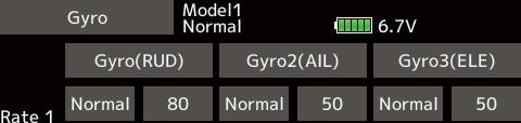
167
168 When using a Futaba governor, this function is used to switch the RPM of the helicopter's head. Up to 3 rates can be set for each condition. *The governor is used by connecting the governor speed setting channel to CH7 (initial setting). *When using an independent governor [ON]/[OFF] switch, connect the AUX([ON]/[OFF]) connector of the governor to CH8 (initial setting) and set the switch to CH8 (Governor2) at the Function menu of the Linkage menu. *When using the Fuel Mixture function, the mixture servo is controlled from the governor. When transmitting the mixture curve data from the transmitter to the governor, the governor AUX (m.trm) connector must be connected to CH8 (initial setting) and governor side setting performed. See the governor instruction manual. Setting method *When the function is set ON/OFF at the governor setup screen, the governor rpm setting channel end point servo travel and limit point are now initialized. *When changed from INH to ACT (ON), the servo travel is initialized to 100 and the limit point is initialized to 155. *When operation is changed to INH at all conditions, the servo travel is initialized to 100 and the limit point is initialized to 135. *When the value is tapped reset to the initial value.
169 *When [rpm] mode is selected above setting, the display mode can be selected. * There is no change in the transmitter output even when the "Mode" is changed. Calibration should be performed via the governor. * In order to use the Governor function of the T16SZ, it is necessary to change the settings on the governor for the low side 700 rpm mode. *For a description of the switch selection method, see the description at the back of this manual. *When the screen is tapped for one second, the sensitivity is reset to the initial value.
170 Common operations used in function setup screen This section describes the functions often used at the function setup screen. Refer to it when setting each function. Tapping the value setting buttons on each screen will cause value input buttons to appear at the top of the panel. Group/single mode switching (Gr/Singl) When setting multiple flight conditions, linking the setting contents with all conditions (group mode) or setting independently (single mode) can be selected. The mode can be changed at the [Gr] item on each setup screen. [Group/single mode switching] Condition delay setting Unnecessary fuselage motion generated when there are sudden changes in the servo position and variations in the operating time between channels can be suppressed by using the condition delay function of the condition select function [Condition select]. When the delay function is set at the switching destination condition, a delay corresponding to that amount is applied and the related functions change smoothly. The same setting contents are set to all " (When the value is tapped, the delay is reset to the initial value.)

171 <Hardware select> screen, and then select " (When the value is tapped, the rate is reset to the initial value.) [Fine tuning VR operation mode] When the VR is turned clockwise and
 and return speed (Out side) can be set individually.")
172 Servo speed setting The servo speed at each function operation (including flight condition switching) can be adjusted. The servos operate smoothly at a fixed speed corresponding to the set speed. The operating speed (In side) and return speed (Out side) can be set individually. Switch the operation mode according to the set function.
173 This section describes the setting procedure of curves which are used with the AFR function and each mixing function. Curve type selection Four types of curves (EXP1, EXP2, Point and Spline) can be selected. Curve type selection
174 Setting by curve type When the curve type is selected as described above, adjustment items corresponding to the curve type appear on the screen. Adjust each curve as described below. EXP1/EXP2 curve adjustment (When the value is tapped, the rate is reset to the initial value.) Using the EXP1 curve is effective in smoothing starting of the ailerons, elevator, rudder, etc. *[Separ.] mode: Normal setting *[Comb.] mode: Using the EXP2 curve is effective in engine rise and other engine control. The curve left and right rates ([Rate A], [Rate B]) and EXP curve rate ([EXP A], [EXP B]) can be adjusted individually. ([EXP] for EXP2) The curve can also be offset horizontally ([Offset]) in the vertical direction. [Rate setting] *Initial value differs depending on function. (When the value is tapped, the rate is reset to the initial value.)
175 Point curves or spline curves of up to 11/17 points can be used. (Initial value: 7/9 points) The set points can be freely increased, decreased, and offset. Point addition method Point deletion method *A new point is created. *The point is deleted.
 *The set points can be freely increased, decreased, and offset. and select the point whose *The mark on the curve shows the currently selected point.")
176 Curve setting operation Spline curve A smoother curve is made. Setting method is same at spline and point. Up to 11 or 17 points curve can be used. (differs with function) *The set points can be freely increased, decreased, and offset. and select the point whose *The mark on the curve shows the currently selected point. Point curve (Point) adjustment Repeat steps 1 through 2 and adjust the Up to 11 or 17 points curve can be used. (differs with function) *[Separ.] mode: Normal setting *[Comb.] mode:

177 The various functions used in the T16SZ can be selected by switch. The switch (including when stick, trim lever, or VR are used as a switch) setting method is common to all functions. Switch selection When a switch is selected at a mixing function, etc., the selection screen shown below is called. When switch is selected Switch ON/OFF setting is possible at each position. When stick, trim lever, or VR is selected. When a stick, trim lever, or VR is used as a switch, the following 4 modes can be selected. Next page
178 Hysteresis-type and box-type can be selected in a hardware select screen. When a stick, trim lever, or VR is used as a switch, the following 4 modes can be selected. This setting method selects function ON/OFF based on the set point. Hysteresis (dead band) can be set to ON and OFF. The ON and OFF positions can be reversed with the Reverse button. The operation is the same as the linear hysteresis mode, but left and right (up and down) operations are symmetrical about the neutral position. For example, when you want to switch DR1 with the aileron stick, when the stick is moved to the left or right, DR1 can be turned ON at the same left and right position. This mode turns on the switch within a range of 2 points. Each point can be set. The ON and OFF positions can be reversed with the Reverse switch. The operation is the same as the linear box mode, but left and right (up and down) operation is symmetrical about the neutral position.

179 When shifting the ON/OFF point The ON/OFF and hysteresis (dead band) boundary point (there are 2 points: top and bottom) position can be shifted. ON/OFF is possible at a free position. and touch the [ON/OFF] same time, Lower Hysteresis Hysteresis (dead band) can be set to ON and OFF set, at the same time,

180 Logic switch (Condition select and DG1, DG2) The logic switch function lets you turn operation on and off by combining two switches. For instance, the condition is activated when 2 switches are turned on. Logic mode Switch mode selection Switch selection Logic mode selection

181 Your Futaba T16SZ transmitter programming can be updated easily online. When functions are added and then use the following procedure to update the program. Check our web site for the FAQ regarding updating for more information. Updating procedure Note: Note: The model data in the transmitter can "FUTABA" "FUTABA" Note:
182 Possible Problems "Low battery." "Write error." In that case, please update again
 First, update a T14SG or FX-22 to the latest software.")
 Save the updated model data to a SD card.")

 complete check of operation with the model to be used.")
183 The model data (only latest version) of T14SG/FX-22 can be copied to T16SZ. * SD card is required. * The model data of T16SZ cannot be copied to T14SG/FX-22. (a) First, update a T14SG or FX-22 to the latest software. (b) Load the model data which failed to convert into the T14SG or FX-22 with the latest software, and the model data should be updated to the latest format. (c) Save the updated model data to a SD card. (d) Retry to convert the updated model data on a T16SZ. * When SD card cannot be recognized, it may be able to be used if it reformats by SD formatter offered from SD Association. SD formatter is downloadable from SD Association (As of June, 2017) complete check of operation with the model to be used. Check well all the directions of operation and all the operation switches. FUTABA CORPORATION Makuhari Techno-Garden Bldg. B-6F, 1-3 Nakase, Mihama-ku, Chiba, , Japan Phone: , Facsimile: FUTABA CORPORATION 2017, 10 (2)
TABLE OF CONTENTS INTRODUCTION... 4 IC O R TION T... 15
 TABLE OF CONTENTS INTRODUCTION... 4... 4... 5 C I... 5 D... 7... 7 OR U... 11... 11 C... 12 R... 12... 13 T... 14 T... 15... 16... 17... 17 D TT1 T6... 18 T T2 212... 19 ON O... 21 T... 22 OITU. NU ON....
14 CHANNEL COMPUTER SYSTEM
 TM TM 1M23N27902 TM TM Technical updates and additional programming examples available at: http://www.futaba-rc.com/faq Entire Contents 2012 INTRODUCTION... 4... 4... 5... 6... 6... 10... 10... 11... 12...
T14MZ Software Update Function Modification Contents (Version: 1.1.0, 1.2.0)
") T14MZ Software Update Function Modification Contents (Version: 1.1.0, 1.2.0) 1M23N14837 Hardware setting This function is for adjusting the sticks, switches and trim characteristics. [System menu] Swash
T14MZ Software Update Function Modification Contents (Version: 1.1.0, 1.2.0) 1M23N14837 Hardware setting This function is for adjusting the sticks, switches and trim characteristics. [System menu] Swash
T18MZ SOFTWARE UPDATE CHANGES
 T18MZ SOFTWARE UPDATE CHANGES (Editor Version: 2.6 Encoder version: 2.3) This software updates or alters the functions and features noted below. The instructions and information that follow are meant as
T18MZ SOFTWARE UPDATE CHANGES
 T18MZ SOFTWARE UPDATE CHANGES (Editor Version: 2.7 Encoder version: 2.3) This software updates or alters the functions and features noted below. The instructions and information that follow are meant as
T18MZ SOFTWARE UPDATE CHANGES
 T18MZ SOFTWARE UPDATE CHANGES (Editor Version: 2.5 Encoder version: 2.2) This software updates or alters the functions and features noted below. The instructions and information that follow are meant as
8-Channel Digital Proportional R/C System INSTRUCTION MANUAL
 INSTRUCTION MANUAL Technical updates and additional programming examples available at: http://www.futaba-rc.com/faq Introduction...6...6...7...9...9...13...13...14...14...15...16...18.22...22...23...24...24...
A3 Pro INSTRUCTION MANUAL. Oct 25, 2017 Revision IMPORTANT NOTES
 A3 Pro INSTRUCTION MANUAL Oct 25, 2017 Revision IMPORTANT NOTES 1. Radio controlled (R/C) models are not toys! The propellers rotate at high speed and pose potential risk. They may cause severe injury
Detrum GAVIN-8C Transmitter
 Motion RC Supplemental Guide for the Detrum GAVIN-8C Transmitter Version 1.0 Contents Review the Transmitter s Controls... 1 Review the Home Screen... 2 Power the Transmitter... 3 Calibrate the Transmitter...
INSTRUCTION MANUAL 1M23N26403
 INSTRUCTION MANUAL 1M23N26403 TABLE OF CONTENTS INTRODUCTION... 4... 33... 4... 5... 6... 6 BEFORE USE... 10... 10... 12... 13... 14 Cautions on handling antenna... 14 LED monitor... 15 Switch reallocation
User Manual Version 1.0
 1 Thank you for purchasing our products. The A3 Pro SE controller is the updated version of A3 Pro. After a fully improvement and optimization of hardware and software, we make it lighter, smaller and
10-Channel Digital Proportional R/C System INSTRUCTION MANUAL
 INSTRUCTION MANUAL Technical updates and additional programming examples available at: http://www.futaba-rc.com/faq Introduction...6...6...7...8...9...12...12...13...13...14...15... 17... 18... 18... 19...
T14MZ Software Update (Editor Version:1.6.0, Encoder Version:1.44)
") T14MZ Software Update (Editor Version:1.6.0, Encoder Version:1.44) 1M23N14850 The T14MZ transmitter software version has been updated; the following functions have been added or modified. Reread the instruction
T14MZ Software Update (Editor Version:1.6.0, Encoder Version:1.44) 1M23N14850 The T14MZ transmitter software version has been updated; the following functions have been added or modified. Reread the instruction
Caution Notes. Features. Specifications. Installation. A3-L 3-axis Gyro User Manual V1.0
 Caution Notes Thank you for choosing our products. If any difficulties are encountered while setting up or operating it, please consult this manual first. For further help, please don t hesitate to contact
14 CHANNEL COMPUTER SYSTEM
 14 CHANNEL COMPUTER SYSTEM TM TM Technical updates and additional programming examples available at: http://www.futaba-rc.com/faq Entire Contents 2012 TABLE OF CONTENTS INTRODUCTION... 4 Support and Service...
EXMITTER -- Professional Remote Control Products Expert
 EXMITTER -- Professional Remote Control Products Expert WARNING The following terms are used throughout the product literature to indicate various levels of potential harm when operating this product.
Introduction. Overview. Outputs Normal model 4 Delta wing (Elevon) & Flying wing & V-tail 4. Rx states
 & Flying wing & V-tail 4. Rx states") Introduction Thank you for purchasing FrSky S6R/S8R (SxR instead in this manual) multi-function telemetry receiver. Equipped with build-in 3-axis gyroscope and accelerometer, SxR supports various functions.
Introduction Thank you for purchasing FrSky S6R/S8R (SxR instead in this manual) multi-function telemetry receiver. Equipped with build-in 3-axis gyroscope and accelerometer, SxR supports various functions.
Detrum MSR66A Receiver
 Motion RC User Guide for the Detrum MSR66A Receiver Version 1.0 Contents Review the Receiver s Features... 1 Review the Receiver s Ports and Connection Orientation... 2 Bind the Receiver to a Transmitter
A3 SUPER 3 INSTRUCTION MANUAL. For Firmware Version 1.0, Data Version 1.0 Oct 25, 2017 Revision.
 A3 SUPER 3 INSTRUCTION MANUAL For Firmware Version 1.0, Data Version 1.0 Oct 25, 2017 Revision support@hobbyeagle.com 1 CONTENTS IMPORTANT NOTES.....3 1. Introduction......4 2. Setup Procedure Overview...5
ORANGE R610V2 RECEIVER USER MANUAL FEATURES:
 ORANGE R610V2 RECEIVER USER MANUAL FEATURES: Compatible with DSM2 aircraft radio and module systems 6 channel cppm output allowing for single line connection with compatible devices True diversity antennas
Fixed Wing Models 55
 Fixed Wing Models 55 Two Snap-Roll programs Automatic switching of control characteristics (access via Set-Up Menu) (access via Set-Up Menu) 56 Fixed Wing Models AUTOMATIC MANOEUVRE The switches to operate
Castle Multi-Rotor ESC Series User Guide
 Castle Multi-Rotor ESC Series User Guide This user guide is applicable to all models of Castle Multi-Rotor ESC. Important Warnings Castle Creations is not responsible for your use of this product or for
CX-1X Mini Heading-Hold Gyro System. Copyright 2014 KY MODEL Company Limited.
 CX-1X2000 Mini Heading-Hold Gyro System INSTRUCTION MANUAL www.copterx.com Copyright 2014 KY MODEL Company Limited. MENU 1. 2. 3. 4. 5. 6. 7. 8. 9. 10. Table of content Introduction Features Specifications
Post-Installation Checkout All GRT EFIS Models
 GRT Autopilot Post-Installation Checkout All GRT EFIS Models April 2011 Grand Rapids Technologies, Inc. 3133 Madison Avenue SE Wyoming MI 49548 616-245-7700 www.grtavionics.com Intentionally Left Blank
T18SZ Model Data Converter (from T18MZ/T14SG to T18SZ only)
") 1M23Z04904 T18SZ Model Data Converter (from T18MZ/T14SG to T18SZ only) Ver.2 Original data of T14SG could be used now. T14SG T18MZ T18SZ The T18SZ Model Data Converter is a software that converts model
1M23Z04904 T18SZ Model Data Converter (from T18MZ/T14SG to T18SZ only) Ver.2 Original data of T14SG could be used now. T14SG T18MZ T18SZ The T18SZ Model Data Converter is a software that converts model
The igyro Simplified!
 The igyro Simplified! I have a confession. Frankly, I am an older person. As such, the common wisdom is that I should move slowly, complain a lot and struggle with new technology. Unfortunately, all three
12FG. 12 CHANNEL RADIO CONTROL SYSTEM PCMG3/PCM1024/FM selectable INSTRUCTION MANUAL
 12FG 12 CHANNEL RADIO CONTROL SYSTEM PCMG3/PCM1024/FM selectable INSTRUCTION MANUAL Note: The battery in the T12FG transmitter is not connected to the battery connector at initial. Please connect the battery
Precaution of Safety. Before using this product, check that you have all of the following items. If any items are missing, please contact dealer.
 USER MANUAL 1 2 Content Before using this product, check that you have all of the following items. If any items are missing, please contact dealer. Introduction Thank you for purchasing HobbyKing.com HK-7X
Smart Bus RRS. Quick Start Guide
 Smart Bus RRS Quick Start Guide Thank you for your purchase of the Advance Radio Smart Bus. In this quick start guide we will show you how to connect your new Smart Bus, General use and Set Up. Please
3PRKA. 3-channel, FHSS Radio control system for Car INSTRUCTION MANUAL 1M23N Digital Proportional R/C System
 3PRKA 3-channel, FHSS Radio control system for Car 1M23N25002 INSTRUCTION MANUAL R Digital Proportional R/C System Thank you for purchasing a Futaba FHSS 3PRKA 2.4GHz system. This system is based on the
System Handling Manual
 Hitec Optic 6 Radio Tutorial For ACRO functions Table of Contents System Modes MODEL SELECTION MODEL NAME MODEL TYPE COPY TRANSMIT SHIFT DIRECTION MODULATION MODE I or MODE II STICK STYLE TIMER SETUP RESET
2.4GHz 6-CHANNEL COMPUTER RADIO INSTRUCTION MANUAL
 TM TTX660 2.4GHz 6-CHANNEL COMPUTER RADIO INSTRUCTION MANUAL Tactic s c TTX660 computer transmitter uses the advanced 2.4GHz spread spectrum SLT Secure Link Technology protocol for solid, interference-free
HM4050 AVCS HEADING LOCK GYRO
 INCLUDES HM4050 gyro with connectors Foam adhesive tape Manual HM4050 AVCS HEADING LOCK GYRO FEATURES AVCS (Angular Vector Control System) Small size Lightweight Able to operate in Heading Hold as well
RADIOLINK T8FB (FHSS) INSTRUCTION MANUAL. 8CH remote control system
 INSTRUCTION MANUAL. 8CH remote control system") RADIOLINK T8FB (FHSS) INSTRUCTION MANUAL 8CH remote control system RADIOLINK ELETRONIC LIMITED Technical updates and additional programming examples available at: www. radiolink.com INTRODUCTION Thank
RADIOLINK T8FB (FHSS) INSTRUCTION MANUAL 8CH remote control system RADIOLINK ELETRONIC LIMITED Technical updates and additional programming examples available at: www. radiolink.com INTRODUCTION Thank
DragonLink Advanced Transmitter
 DragonLink Advanced Transmitter A quick introduction - to a new a world of possibilities October 29, 2015 Written by Dennis Frie Contents 1 Disclaimer and notes for early release 3 2 Introduction 4 3 The
8 Channel 2.4GHz. Operation Manual DIGITAL PROPORTIONAL SYSTEM. dual modulation spectrum system
 DIGITAL PROPORTIONAL SYSTEM 8 Channel 2.4GHz dual modulation spectrum system Operation Manual Prior to use, please read this manual thoroughly. Keep this manual in a convenient place for quick and easy
Xtreme Power Systems
 Xtreme Power Systems XtremeLink NANO RECEIVER Installation And Usage Manual XtremeLink is a registered trademark of Xtreme Power Systems, LLC. Firmware v 1.9 Manual v 1.9 Revision Date: November 11 th,
DE1103 PLL FM STEREO/SW.MW.LW DUAL CONVERSION SYNTHESIZED WORLD RECEIVER OPERATION MANUAL
 DE1103 SYNTHESIZED WORLD RECEIVER SYNTHESIZED WORLD RECEIVER DE1103 OPERATION MANUAL INDEX POWER SUPPLY POWER SUPPLY... 1 POWER INDICATION... 3 BATTERY CHARGER... 4 BEFORE OPERATION..... 6 SET THE CLOCK...
Table of Contents Introduction/ Table of contents.. System Specifications Transmitter
 Introduction Thank you for purchasing the Hitec Laser digital proportional radio control system. The Laser is loaded with features, easy to use and utilizes the latest in solid-state components for unsurpassed
PROGRAMMING GUIDE FOR A SIX-SERVO SAILPLANE
 PROGRAMMING GUIDE FOR A SIX-SERVO SAILPLANE SPEKTRUM DX6 - DX9 - DX18 G2 By: Sherman Knight July 2014 Guide Version 4.0 Template Ver. 4.0 AirWare Version DX18 G2 Ver. 1.02 Voice Ver. 1.04 Airware Version
Instruction Manual Bedienungsanleitung Manuel d utilisation Manuale di Istruzioni
 6 6e Instruction Manual Bedienungsanleitung Manuel d utilisation Manuale di Istruzioni NOTICE All instructions, warranties and other collateral documents are subject to change at the sole discretion of
YGE ProgCard II - Programming Card
 YGE ProgCard II - Programming Card With the programming card, we offer an easy to use programming unit, with which all our ProgCard II capable speed controllers can have their individual functions changed.
Table Of Contents. For Your Safety As Well As That Of Others...8
 2 3 Table Of Contents For Your Safety As Well As That Of Others...8 Explanation Of Symbols...8 2.4GHz System Precautions...8 Receiver Mode Precautions...8 Operation Precautions...9 NiMH/NiCd/LiFe Battery
CHAPTER 1: TRANSMITTER CONTROLS Helicopter
 CHAPTER 1: TRANSMITTER CONTROLS Helicopter 1.1 CONTROL IDENTIFICATION AND LOCATION Mode II ANTENNA THROTTLE TRIM CARRYING HANDLE TRAINER BUTTON GEAR SWITCH LCD SCREEN ELEVATOR TRIM AUX 1/FLAP MIXING ELEVATOR
Product Introduction:
 Product Introduction: ARKBIRD-433UHF is a 10-channel module designed for long-distance flight: 1. The advanced code division frequency hopping system (FHSS) produces the only way of frequency hopping sequence
Manual for Hyperion Receivers 1. Binding Step 1. Power up the receiver in bind mode
 - This is not a Horizon Hobbies DSM2, DSMX product, and is not manufactured or endorsed by Horizon Hobbies LLC. DSM2, and DSMX are registered trademarks of Horizon Hobbies LLC. Manual for Hyperion Receivers
SPEKTRUM DX18. Programming Guide for a Six-Servo Sailplane. By: Sherman Knight July Version 2.0 AirWare Version 1.0
 SPEKTRUM DX18 Programming Guide for a Six-Servo Sailplane By: Sherman Knight July 2012 - Version 2.0 AirWare Version 1.0 The DX18 takes the best from many different radios combining them into one of the
INSTRUCTION MUNUAL for Futaba 6EXHP 6-channel, PCM/PPM(FM) selectable Radio control system for helicopter
 selectable Radio control system for helicopter") INSTRUCTION MUNUAL for Futaba 6EXHP6-channel, PCM/PPM(FM) selectable Radio control system for helicopter Futaba Corporation Technical updates available at: http://www.futaba-rc.com Entire Contents Copyright
INSTRUCTION MUNUAL for Futaba 6EXHP6-channel, PCM/PPM(FM) selectable Radio control system for helicopter Futaba Corporation Technical updates available at: http://www.futaba-rc.com Entire Contents Copyright
DXXX Series Servo Programming...9 Introduction...9 Connections HSB-9XXX Series Servo Programming...19 Introduction...19 Connections...
 DPC-11 Operation Manual Table of Contents Section 1 Introduction...2 Section 2 Installation...4 Software Installation...4 Driver Installastion...7 Section 3 Operation...9 D Series Servo Programming...9
EXMITTER -- Professional Remote Control Products Expert
 EXMITTER -- Professional Remote Control Products Expert WARNING The following terms are used throughout the product literature to indicate various levels of potential harm when operating this product.
Arkbird Hummingbird BNF Version Airplane User Manual Caution
 Arkbird Hummingbird BNF Version Airplane User Manual Caution 1) Please abide by relevant laws: No flying in populated area, no flying in airport clearance area (10km away from both sides of the runway,
Instructions for Crack Series / Superior RX
 Instructions for Crack Series / Superior RX DSMX and DSM2 Compatibility Superior Rx receivers work with both DSM2 and DSMX versions. DSMX is a development of the earlier DSM2 specification that includes
Spektrum AirWare Change Log 2018-Jan-18
 Version 1.21.07 Changes listed below are since 2017-July-11. For more info visit http://spektrumrc.cachefly.net/airwarechangelogs.html Special Notes In the Telemetry menu, some sensors may not be reported
R PROFLAME Instruction Book Collection
 9.956.028 R00 584 PROFLAME Instruction Book Collection 4-17 18-29 584 PROFLAME System 30-39 Appendix: DIP SWITCH NUMBER (0=ON 1=OFF) 40-41 4-17 Fig. 1 The SIT is a device that allows, in conjunction with
XP CHANNEL COMPUTER RADIO SYSTEM
 INSTRUCTION MANUAL FOR AIRPLANE AND HELICOPTER XP6102 6-CHANNEL COMPUTER RADIO SYSTEM TABLE OF CONTENTS TABLE OF CONTENTS TABLE OF CONTENTS...2 CHAPTER 1: USING THIS MANUAL INTRODUCTION...6 Using this
PCM/PPM(FM) selectable Radio control system for aircraft
 selectable Radio control system for aircraft") INSTRUCTION MANUAL for Futaba 6EXAP 6-channel, PCM/PPM(FM) selectable Radio control system for aircraft Futaba Corporation Technical updates available at: http://www.futaba-rc.com Entire Contents Copyright
INSTRUCTION MANUAL for Futaba 6EXAP 6-channel, PCM/PPM(FM) selectable Radio control system for aircraft Futaba Corporation Technical updates available at: http://www.futaba-rc.com Entire Contents Copyright
Manual. mz-10 HoTT 6 channel 2,4 GHz transmitter. mz-10. No. S1042 No. S Copyright Graupner/SJ GmbH
 EN Manual mz-10 HoTT 6 channel 2,4 GHz transmitter No. S1042 No. S1042.77 mz-10 Copyright Graupner/SJ GmbH 2 / 48 Index Introduction... 5 Service centre... 5 Intended use... 6 Target group...6 Package
RADIOLINK T8FB (FHSS) INSTRUCTION MANUAL. 8CH remote control system
 INSTRUCTION MANUAL. 8CH remote control system") RADIOLINK T8FB (FHSS) INSTRUCTION MANUAL 8CH remote control system RADIOLINK ELETRONIC LIMITED Technical updates and additional programming examples available at: www. radiolink.com INTRODUCTION Thank
RADIOLINK T8FB (FHSS) INSTRUCTION MANUAL 8CH remote control system RADIOLINK ELETRONIC LIMITED Technical updates and additional programming examples available at: www. radiolink.com INTRODUCTION Thank
Wireless Copilot. Safe2Fly - Height Only Version. Page NanoQuip Ltd
 Wireless Copilot Safe2Fly - Height Only Version Page Contents Warnings... 3 Features... 4 Specifications... 5 Installation... 6-8 Receiver Battery... 6 Transmitter Installation... 7-8 How to Use This Manual...
OPERATING INSTRUCTION
 No. S1001 OPERATING INSTRUCTION Prior to use, please read this manual thoroughly. Keep this manual in a convenient place for quick and easy reference. Before Use Support and Service - Customer support
Copyright Graupner/SJ GmbH. Manual. Vector Unit / Vector Unit Extreme 2 channel HoTT 2,4 GHz receiver/servo/speed controller unit No No.
 Copyright Graupner/SJ GmbH EN Manual Vector Unit / Vector Unit Extreme 2 channel HoTT 2,4 GHz receiver/servo/speed controller unit No. 34002 No. 34003 Index Introduction... 4 Service Center... 4 Intended
4YWD 4-channel, FHSS Radio control system for EP Car INSTRUCTION MANUAL 1M23N Digital Proportional R/C System
 4YWD 4-channel, FHSS Radio control system for EP Car INSTRUCTION MANUAL 1M23N28702 R Digital Proportional R/C System Thank you for purchasing a Futaba 4YWD FHSS 2.4GHz system. This system is based on the
Smart Bus RRS. Quick Start Guide
 Smart Bus RRS Quick Start Guide Thank you for your purchase of the Advance Radio Smart Bus RRS. In this quick start guide we will show you how to connect your new Smart Bus, General use and Set Up. Please
computer radio control system CZECH REPUBLIC DC/DS GHz/900MHz Dual Band System FW 4.10
 CZECH REPUBLIC DC/DS-24 2.4GHz/900MHz Dual Band System FW 4.10 1. Introduction... 07 3.3.5 Throttle stick travel adjustment... 16 1.1 DC/DS...07 3.3.6 Changing the transmitter mode... 16 1.2 Features...
FORZA 700 SPEED Supplemental manual
 The FORZA 700 has evolved into a Speed Monster. The finely honed form minimizes air resistance, and the forward tilting rotor head helps transform all available power into speed. Fly beyond limits with
Copyright Graupner/SJ GmbH. Manual. mz-4 2 channel HoTT 2,4 GHz transmitter No. S1031
 Copyright Graupner/SJ GmbH EN Manual mz-4 2 channel HoTT 2,4 GHz transmitter No. S1031 Index Introduction... 4 Service Centre... 4 Intended use... 5 Package content... 5 Technical Data... 5 Symbols Explication...
New functions and changes summary
 New functions and changes summary A comparison of PitLab & Zbig FPV System versions 2.50 and 2.40 Table of Contents New features...2 OSD and autopilot...2 Navigation modes...2 Routes...2 Takeoff...2 Automatic
INSTRUCTION MANUAL VHF FM TRANSCEIVER TK-7102H UHF FM TRANSCEIVER TK-8102H KENWOOD CORPORATION B (M)
") INSTRUCTION MANUAL VHF FM TRANSCEIVER TK-7102H UHF FM TRANSCEIVER TK-8102H KENWOOD CORPORATION B62-1596-00 (M) 09 08 07 06 05 04 03 02 01 00 THANK YOU! We are grateful you chose KENWOOD for your personal
INSTRUCTION MANUAL VHF FM TRANSCEIVER TK-7102H UHF FM TRANSCEIVER TK-8102H KENWOOD CORPORATION B62-1596-00 (M) 09 08 07 06 05 04 03 02 01 00 THANK YOU! We are grateful you chose KENWOOD for your personal
10. Racers Tips. - The most important thing to remember is to have fun!
 8. Troubleshooting Guide Question: I installed the batteries in my transmitter, but the power lights do not come on: Answer: - Check that the batteries are properly installed by checking the polarity (+
Thank you for purchasing our product, an ideal radio system for beginners or experienced users alike.
 Thank you for purchasing our product, an ideal radio system for beginners or experienced users alike. Read this manual carefully before operation in order to ensure your safety, and the safety of others
The flying manual. Quique s Signature series 72 YAK 54
 Quique s Signature series 72 YAK 54 The flying manual Thank you for purchasing the most exiting aerobatic airplane of this class. This 72 YAK 54 is a scaled down version of the YAK-54 TOC model that my
Connect + compatible
 Connect + compatible Looking for a quick setup up guide? There is lots of useful information in this book, but if all you are after is quick set up look for the following headings in this book 1) Setting
MTC-2 highlight features: ACU highlight features: Contents. MTC-2 and ACU User Manual V5.1
 MTC-2 can work alone as a twin motor ECS (electronic speed controller) for RC tanks. When the ACU (auxiliary control unit) is connected, it can also control turret rotation, gun elevation, gun firing,
TS6 2.4GHz 6CH Radio Control System. Instruction manual. No.8610
 TS6 2.4GHz 6CH Radio Control System Instruction manual No.8610 Introduction Congratulations on your purchase of the Innovator TS6 + advanced 6 Channel 2.4GHz spread spectrum radio control system. This
2/3 CHANNELS FOR AIRCRAFT 2FR/3FR
 2/3 CHANNELS FOR AIRCRAFT 2FR/3FR 1M23N09002 Thank you for purchasing a Futaba SKYSPORT SS2/SS3. Before using your SKYSPORT SS2/SS3, read this manual carefully and use your R/C set safely. After reading
Copyright Graupner/SJ GmbH. Manual. mz-4 2 channel HoTT 2,4 GHz transmitter No. S1031
 Copyright Graupner/SJ GmbH EN Manual mz-4 2 channel HoTT 2,4 GHz transmitter No. S1031 Index Introduction... 4 Service Centre... 4 Intended use... 5 Package content... 5 Technical Data... 5 Symbols explication...
Dear Valued Customer,
 Dear Valued Customer, Thank you for choosing Listen! All of us at Listen are dedicated to provide you with the highest quality products available. We take great pride in their outstanding performance because
SebArt professional line
 SebArt professional line Wind S 110 ARF ASSEMBLY MANUAL The new Wind S 110 ARF was designed by Italy aerobatic pilot, Sebastiano Silvestri. This professional ARTF kit is the result of Sebastiano s 20 years
NOTICE All instructions, warranties and other collateral documents are subject to change at the sole discretion of Horizon Hobby, LLC.
 Instruction Manual NOTICE All instructions, warranties and other collateral documents are subject to change at the sole discretion of Horizon Hobby, LLC. For up-to-date product literature, visit horizonhobby.com
INDEX POWER SOURCES OPERATING ON BATTERY BATTERY REPLACEMENT
 INDEX SOURCES... 1 OPERATING ON BATTERY... 1 OPERATING ON AC ADAPTOR... INDICATION... 3 BATTERY... 3 CLOCK FUNCTION...4 SET THE CLOCK...4 SELECT TIME MODE...5 MW STEP 9K/10K SELECTION...5 TURN ON / OFF
August/5/2010 FY-20A FLIGHT STABILIZATION SYSTEM TECH INSTALLATION & OPERATION MANUAL
 August/5/2010 FEIYU TECH FY-20A FLIGHT STABILIZATION SYSTEM INSTALLATION & OPERATION MANUAL Dear Pilot, Thank you for purchasing the FY-20A stabilizer from FeiYu Tech. In order to achieve full potential
INSTRUCTION MANUAL. For T GHz PCM Channel RADIO CONTROL SYSTEM. For Airplanes/Helicopters CE
 INSTRUCTION MANUAL For T810 2.4GHz PCM1024 8-Channel RADIO CONTROL SYSTEM For Airplanes/Helicopters CE0678 www.hkswift.com Thank you for purchasing digital model T810 remote control. This manual will give
Modified Spektrum DM9 Module for Use with Futaba 8FG, 12FG, 14SG and 18SZ Transmitters INSTRUCTIONS
 Modified Spektrum DM9 Module for Use with Futaba 8FG, 12FG, 14SG and 18SZ Transmitters INSTRUCTIONS Ivan Cankov (ivanc on RCGroups) Modified Spektrum DM9 Module for Use with Futaba 8FG, 12FG, 14SG and
SYSTEM INSTRUCTION MANUAL
 SYSTEM INSTRUCTION MANUAL FM/QPCM Acro / Glider Heli Three in One Table of Contents Introduction to the Optic System 3 About this manual 3 Optic System Options: 3 Flying Safety 4 Airplane Frequencies 5
INSTRUCTION MANUAL YAW-AXIS STABILIZER FOR MODEL HELICOPTER (RATE GYRO) 1M23N21902
 1M23N21902") INSTRUCTION MANUAL YAW-AXIS STABILIZER FOR MODEL HELICOPTER (RATE GYRO) 1M23N21902 Thank you for purchasing a GY520 AVCS gyro. Before using your new gyro, please read this instruction manual thoroughly
INSTRUCTION MANUAL YAW-AXIS STABILIZER FOR MODEL HELICOPTER (RATE GYRO) 1M23N21902 Thank you for purchasing a GY520 AVCS gyro. Before using your new gyro, please read this instruction manual thoroughly
Trimming your Aerobatic Model
 Trimming your Aerobatic Model When we speak of trimming your aerobatic model we re not talking about trimming in the traditional sense of adjusting the control surfaces to maintain level flight. In this
TaBLE OF contents. Packaging
 Page 1 TaBLE OF contents Introduction... Page 3 Additional Receiver Information... Page 3 Transmitter Signal Range... Page 3 FCC Compliance Statement... Page 3 Safety and Usage Precautions... Page 4 General
MTC-2 highlight features: ACU highlight features: Contents. MTC-2 and ACU User Manual V4.0
 MTC-2 can work alone as a twin motor ECS (electronic speed controller) for RC tanks. When the ACU (auxiliary control unit) is connected, it can also control turret rotation, gun elevation, gun firing,
INSTRUCTION MANUAL FOR AIRPLANE, HELICOPTER AND SAILPLANE X CHANNEL COMPUTER
 INSTRUCTION MANUAL FOR AIRPLANE, HELICOPTER AND SAILPLANE X-378 7-CHANNEL COMPUTER TABLE OF CONTENTS I. INTRODUCTION Table of Contents 2 1. Using The Manual 4 2. Features 4 2.1 Transmitter 4 2.2 Receiver
MTC-2 highlight features: ACU for Flakpanzer Gepard highlight features: Contents. MTC-2 and ACU User Manual V4.2 (Flakpanzer Gepard Version)
") This manual is written for the ACU for Flakpanzer Gepard. There are some modifications on usage of servo and LED ports. Please also notice that GSU (gun stabilize unit) is not supported. MTC-2 highlight
This manual is written for the ACU for Flakpanzer Gepard. There are some modifications on usage of servo and LED ports. Please also notice that GSU (gun stabilize unit) is not supported. MTC-2 highlight
STANDARD FL Description, Connection Diagram Menu Block Diagram Diagram of Adjustments Control Programmes (V-Tail, Delta)...
...") Contents General Instructions mc-16/20 Computer System 3 5 Basic Installation Instructions... 6 9 Connecting External Elements...10 Installing Modules...11 Compatibility...12 Starting Out...12 Multi-Data
Contents General Instructions mc-16/20 Computer System 3 5 Basic Installation Instructions... 6 9 Connecting External Elements...10 Installing Modules...11 Compatibility...12 Starting Out...12 Multi-Data
DIGITAL PROPORTIONAL RADIO CONTROL SYSTEM INSTRUCTION MANUAL
 - DIGITAL PROPORTIONAL RADIO CONTROL SYSTEM INSTRUCTION MANUAL - Thank you for purchasing our product, an ideal radio system for beginners or experienced users alike. Read this manual carefully before
Using the 9XR Pro for More than Eight Channels
 Appendix B Using the 9XR Pro for More than Eight Channels Introduction In stock form, with a module such as the FrSky DJT or OrangeRx DSMX/DSM2 installed, the Turnigy 9XR Pro transmitter can control a
4YF-2.4GHz INSTRUCTION MANUAL for Futaba 4YF-2.4GHz
 4YF-2.4GHz INSTRUCTION MANUAL for Futaba 4YF-2.4GHz 4-channel, FHSS Radio control system for Airplanes Futaba Corporation Technical updates available at: http://www.futaba-rc.com Entire Contents Copyright
BFS / BFSM SERIES Installation & Maintenance Manual
 Introduction: The BFS / BFSM series electric actuators have battery backup modules for fail safe operation. The BFS series is for two position control and the BFSM series is for proportional control, both
DPC-10. DPC-10 Software Operating Manual. Table of Contents. Section 1. Section 2. Section 3. Section 4. Section 5
 Table of Contents Section 1 Section 2 Section 3 Section 4 Section 5 About the Software Test Function Programming Functions Connections Basic Mode Connection RC Mode Connection Using the DPC-10 Test Functions
Modellbau Lindinger GmbH. Operating Instructions. FX-22 No. F Modellbau Lindinger GmbH
 Operating Instructions FX-22 No. F 8079 Contents Contents Please be sure to observe the Safety Notes. 1. set contents...4 2. General description...4 2.1 FX-22 transmitter...4 2.2 R7008SB receiver...5 2.3
VHF Transceiver AR6201
 VHF Transceiver AR6201 Operating Instructions Issue 2 / October 2010 Article No. 0618.764-071 Becker Flugfunkwerk GmbH Baden-Airpark B 108 77836 Rheinmünster Germany Telefon / Telephone +49 (0) 7229 /
(Build Instructions)
") (Build Instructions) Specifications * Wingspan: 58cm * Length: 50cm * Flying Weight: 59 grams * Channels: 3 (Rudder Elevator Throttle) * Suggested Receiver: 4Ch Micro * Motor: 8mm GearDrive * Prop: GWS
(Build Instructions) Specifications * Wingspan: 58cm * Length: 50cm * Flying Weight: 59 grams * Channels: 3 (Rudder Elevator Throttle) * Suggested Receiver: 4Ch Micro * Motor: 8mm GearDrive * Prop: GWS
Headset Intercom System. Operating Instructions
 Headset Intercom System Model C1025 Operating Instructions Headset and Transceiver Pack Base Station Model C1025 Table of Contents Intended Use...iii FCC Information...iii Service...iii System Descriptions...1