UM-525. Marine Radio OWNER S MANUAL
|
|
|
- Spencer Hawkins
- 5 years ago
- Views:
Transcription


1 UM-525 Marine Radio OWNER S MANUAL
2 Maritime Rade Op Warning! This transmitter will operate on channels/frequencies that have restricted use in the United States. The channel assignments include frequencies assigned for exclusive use of the U.S. Coast Guard, use in Canada, and use in international waters. Operation on these frequencies without proper authorization is strictly forbidden. For frequencies/ channels that are currently for use in the U.S. without an individual license, please contact the FCC Call Center at CALL-FCC. For individuals requiring a license, such as commercial users, you should obtain a license application from your nearest FCC field office (for US users) or Industry Canada (for Canadian users). FCC / Industry Canada Information Certification FCC Part 80 or RSS-182/188 Output Power 1 Watt (low) and 25 Watts (high) Emission 16K0F3E, 16K0F2D Transmitter Frequency Range to MHz FCC Identifier AMWUT601 IC Certification Number 513C-UT601D This device complies with the GMDSS provisions with Part 80 of the FCC Rules, as well as Part 15 of the FCC Rules. Operation is subject to the condition that this device does not cause harmful interference. Unauthorized changes or modifications to this equipment may void compliance with the FCC Rules. Any change or modification must be approved in writing by Uniden Corporation. Changes or modifications not approved by Uniden could void the user s authority to operate the equipment. The cords on this product and/or accessories contain lead, a chemical known to the State of California to cause birth defects or other reproductive harm. Wash hands after handling. Uniden works to reduce lead content in our PVC coated cords in our products and accessories. Installer Instructions Maritime Radio Services Operation To connect an optional external antenna to the radio for your WHAM x 4, you will need a 2.4GHz antenna with mounting bracket and a cable with N-type male connectors. Keep the antenna lead-in wire as short as possible. Follow these steps to connect an optional external antenna to the radio. 1. Use a mounting bracket to mount the antenna on a vertical mast or pole. 2. Run the cable from the antenna to the radio. 3. Attach one end of the cable to the connector lug on the antenna, then connect the other end to the External Antenna Connector jack on the back of the radio. 2 Marine Radio Services Operation
3 Contents About Contents Digital Selective Calling...5 Introduction...6 Feature Highlights...6 General Features... 6 Weather Features... 7 DSC Features... 7 Optional Features... 8 Understanding Your Radio...9 About This Manual... 9 How The Radio s Controls Appear in This Manual... 9 Controls, Connections, and Indicators...11 Front Panel Rear Panel Connectors Hailer Connector/Cable GPS/External Speaker Connector/Cable WHAM Control Unit Connector Setting Up The Radio...13 Connecting the Antenna Connecting Power Installation Using a WHAM or WHAM x 4 Microphone With the Radio Using One or Two Hailer Horns With the Radio A Look at the Radio A Look at the Microphone A Look at the Display Basic Operation...18 Turning the Radio On and Off Selecting a Channel Transmitting and Receiving Adjusting the Transmit Power Using Scan Using All Channel Scan Using Step Using Hail Using the Intercom Using GPS Using Battery Hi/Lo Detect Using 16/9 TRI Using Memory Channel Scanning Memory Channels Using Triple Watch Contents 3
4 Using the Scrambler Using the Weather Function Performing a Radio Self Test DSC Operation Sending a DSC Distress Call Receiving a DSC Distress Call The Radio Menu Settings for DSC Call and Fog Horn Using the DSC Call Menu Setting DSC Call Options Setting the Fog Horn Options The Setup Screen Options Using the Initialize Sub Menu Setting Up a User MMSI Setting the Vessel Type Setting the Fog Horn Frequency Adjusting the Backlight Adjusting the Key Beep Adjusting the Color Pallet Setting the Local Time - Time Adjust and Time Entry Using the Radio Sub Menu Channel Name Settings Setting FIPS Codes Disabling Auto Channel Switch Position Reply Setting Up a Group MMSI Setting Channel Scan Setting RX Sensitivity Displaying Time and Position Setting the XTRACK Beep Options Using the WHAM and WHAM x 4 Sub Menus Using the Hailer Rename Option Using the Scrambler Menu Using the WHAM Page Sub Menu Using the Crosstrack (XTRACK) Screen Viewing the Compass Screen Using the Digital Menu Care and Maintenance Frequently Asked Questions Specifications Appendix NMEA Operation Reference Information Three Year Limited Warranty Contents
5 About Digital Selective Calling About Digital Selective Calling Digital Selective Calling DSC is a technique used by marine radio systems to augment calling the another station by voice. It permits other vessels to be called up by keying in a unique identity number known as the MMSI. It also provides a button that will generate a distress alert identifying the vessel in distress, the nature of the problem and a position derived from an installed, optional Global Positioning Satellite (GPS) device. The feature was implemented in February 1999 as an integral part of the Global Maritime Distress and Safety System (GMDSS). Digital Selective Calling (DSC) lets mariners instantly send automatically formatted distress alerts to rescue authorities anywhere in the world. Digital selective calling also lets mariners initiate or receive distress, urgency, safety and routine radiotelephone calls to or from any similarly equipped vessel or shore station, without requiring either party to be near a radio loudspeaker. DSC acts like the dial and bell of a telephone, allowing you to direct dial and ring other radios, or allow others to ring you, without having to listen to a speaker. Your radio's DSC Call feature lets you transmit and receive DSC Calls based on ITU-R M For a detailed discussion of this standard, you can refer to the following web site document: and read a full explanation on line. If you have an optional GPS installed, you can send a distress message in an emergency situation which includes your position. You can also send and receive position data to and from other vessels. Additionally, you can set up and use a directory of other vessels with DSC radios. The radio's NMEA input and output feature lets you display and use vessel information. When equipped with an optional GPS, the UM625c can send and receive DSC calls that include the following information: distress, individual, individual ack(nowledgement), all ships, group, position request, position reply, and position send. DSC calls to your radio can receive include distress ack, geographic, distress relay, and distress relay ack. Mobile Maritime Service Identity (MMSI) This refers to a unique nine digit identification number designated for each qualified vessel or shore station. It is in a way, a maritime equivalent of a telephone number. You must obtain your personal MMSI before you can program and or transmit data mentioned above. If you have access to the web, open either and navigate to the convenient MMSI application form provided. Or, go to and complete the on-line form provided. If you do not have web access, you can call, toll free, BoatUS, in Alexandra, VA at and request that the MMSI form be mailed or faxed to you. This presumes you use a recreational vessel in domestic U.S. waters and that you are not otherwise required to be licensed. Because BoatUS is set up to take advantage of an electronic registration system, using standard mail or fax will be much slower. You can also call the FCC Forms Distribution Center at who then will provide you with the form types they require. About Digital Selective Calling 5
6 Introduction Introduction Your Uniden UM625c Marine Radio combines state-of-the-art technology with rugged durability and ease of use. The radio's all solid-state design and conservatively-rated components and materials make it an ideal choice for harsh marine environments. The radio's large color display and backlit control buttons make it easy to use even in extreme lighting and weather conditions. The radio's memory channel scan feature lets you set it so it quickly scans and tunes only the channels you select. The Triple Watch feature lets you easily scan Coast Guard calling, hailing, and distress channels along with any channel you want, and you can tune Coast Guard calling, hailing, and distress channels by pressing a single button. The weather alert features let you monitor weather alert broadcasts and even sound an audible alarm if bad weather is reported in an area you specify. You can connect an optional GPS module to the radio to help keep track of your current location with space-age precision. You can connect and use a wide variety of optional equipment with the radio, including an FMB321 flush mount, 2 hailer horns, GPS module, wireless microphones, and a plotter. You can connect and use up to two WHAM or four WHAM x 4 wireless microphones with the radio, making onboard communications as flexible as you need them to be. You can even install an optional scrambler board in the radio letting you communicate privately with other vessels that have a scrambler installed. You should read the rest of this Operating Guide thoroughly to acquaint yourself with all of your radio's features and functions. Save your receipt as proof-of-purchase in case you need to obtain warranty service. Features, specifications, and availability of optional accessories are all subject to change without notice. Note: Your radio meets the stringent JIS7 waterproof specification. This means that the radio and microphone can be submerged to a depth of 1 meter for up to 30 minutes without incurring damage. Feature Highlights Feature Highlights General Features Channel Scan - You can set the radio so it scans only the channels you select or all channels. Triple Watch - The radio lets you scan Coast Guard/Distress/Hailing Channel 16, secondary Coast Guard/Distress/Hailing Channel 9, and the currently selected channel in order. Memory Channel Step - You can set the radio so it quickly tunes channels saved in the radio's memory. Help Screen - The radio has help information built into it, making it easy to find out about any of the radio s features or operations. Demo Mode - In RADIO mode, press and hold MENU and HI-LO at the same time. The radio s automatic demo mode starts. Do nothing further while the demonstration runs. To exit the demo, press and hold MENU and HI-LO again. 6 Introduction Feature Highlights
7 One-Touch Emergency Channel - You can quickly tune the radio to Coast Guard/Distress/ Hailing Channel 16 and secondary Coast Guard/Distress/Hailing Channel 9 by pressing a single button. Hi/Lo Transmit Power - You can set the radio's transmit power to 25 watts or 1 watt. Channel Mode - You can set the radio's channel mode to USA, INT (international), or CAN (Canada). Automatic and Manual Display Backlight Adjustment - The display automatically sets its brightness for day or night operation, to make it easier to see in extreme conditions. You can also manually adjust the backlight. LCD Color Adjustment - You can adjust the LCD colors on the display to let you see them easier at night. Key Beep Adjustment - You can adjust the volume of the tone you hear when you press a key. Self Test - The radio automatically tests its hardware and displays the test results. Channel Name - Lets you change the channel name that appears when you tune a channel. Auto Position Reply Disable - You can set the radio so when it receives a position request call, it does not automatically reply with your current position. Attenuator - You can set the radio so it attenuates (reduces) reception of strong signals. Standby - You can set the radio to its unattended mode. Receive Log - You can view the receive log, making it easy to see when somebody calls your vessel. Weather Features WX Alert Decode Mode - You can set your radio to monitor a selected weather radio channel for weather emergency signals or SAME (Specific Area Message Encoding) alerts for areas you specify. This lets you receive early warning when bad weather is in the area or a national, regional, or local emergency has been detected. FIPS Code Programming - You can program your radio with up to 30 FIPS (Federal Information Processing Standard) codes for the areas you desire. If the radio receives a SAME alert tone, it checks it against the FIPS codes you programmed and alerts you if it finds a match. DSC Features DSC Call - You can use the radio to transmit and receive DSC Call information. See Using the DSC Call Menu on Page 26 for more information. DSC Directory - You can set up a directory of other vessels that have a DSC-capable radio with a Maritime Mobile Service Identity (MMSI) number. Auto Channel Switch Disable - You can set the radio so it does not automatically change the working channel when it receives a DSC Call. The radio automatically sends a signal to Feature Highlights 7
8 the calling vessel that shows that your vessel's radio is unattended, and does not tune to the requested channel. Optional Features Scrambler - Install an optional scrambler board in the radio, so you can set the radio to scramble your voice when you transmit, helping you avoid being overheard by other vessels. Hailer Features - You can use these features if you connect one or two optional hail horns to the radio. Loud Hailer - You can use the radio to talk and listen using the speaker. Fog Horn - You can use the radio to sound a fog horn. If you connect an optional GPS receiver to the radio, the radio can even sound the appropriate fog horn sound based on the type of vessel where the radio is installed (sail, power, or tow), and whether the vessel is moving or stopped. GPS Features - You can use these features if you connect an optional GPS receiver to the radio. GPS Intuitive - The radio automatically suggests the correct channel mode based on its current location (USA, International, and Canadian channels). Automatic Local Time Setting - The radio sets itself to the correct local time. Automatic Fog Horn - The radio sounds the appropriate fog horn sound based on the type of vessel where the radio is installed (sail, power, or tow), and whether the vessel is moving or stopped. NMEA Input - Connect an optional GPS receiver to the radio, to display information such as your vessel's latitude and longitude, speed and course, and the date and time. You can also send position information and use GPS Intuitive data using this feature. NMEA Output - The radio automatically passes received DSC information to an optional connected chart plotter. WHAM Input - If you connect up to two optional 900 MHz analog WHAM microphones to the radio, you can use it to control the radio from almost anywhere aboard your vessel. WHAM x 4 Input - Connect up to four optional 2.4 GHz digital WHAM x 4 microphones to the radio, that you can use it to control the radio from almost anywhere aboard your vessel, and each WHAM x 4 user can communicate with another WHAM x 4 user. You can also use the radio's intercom function to communicate with each WHAM x 4 user. You can even use a second base radio as an intercom. 8 Feature Highlights
9 Understanding Your Radio About This Manual Understanding Your Radio The screen displays used in this manual are representations of what might appear when you use your radio. Since what you see depends on the frequencies for your area and the settings you select, you might notice some differences between what is in this manual and what appears on your radio's display. Buttons you press appear in BOLD type, icons that appear on the display appear in BOLD REVERSED type, and text that appears on the display appears in italic type. How The Radio s Controls Appear in This Manual To help navigate the radio's menus, the steps shown in this manual describe the displays you see and the keys you press or control you operate to get a desired result. This example shows you how to use the radio's menu to program a user MMSI for the first time. The MMSI is a unique nine digit identification number allocated to each vessel or shore station. It is analagous to a normal telephone number. This example shows you the button to press (PUSH/SELECT) to view a series of choices, the control to use (PUSH/SELECT) to view and select more choices, and the correct options to select (SETUP and USER MMSI) as you rotate PUSH/SELECT. It also instructs you to press PUSH/SELECT to select the options. Important: If you have already set the user MMSI, DO NOT CHANGE IT unless you have received a new user MMSI. After you program a user MMSI for the first time, you can only change it once more. If you try to change the user MMSI a third time, the radio will not accept the change. To change the user MMSI again, you must return the radio to Uniden for reprogramming. 1. Quickly press and release PUSH/SELECT. A screen appears containing options you can select to work with the radio's features. 2. Rotate PUSH/SELECT to select SET UP, then press PUSH/SELECT to select it. 3. Press PUSH/SELECT to select INITIALIZE. 4. Rotate PUSH/SELECT to select USER MMSI, then press PUSH/SELECT to select it. If a user MMSI has already been programmed once or twice, it appears on the screen. Stop here. Understanding Your Radio 9
10 Otherwise, if a user MMSI has not been programmed, the first digit of the blank user MMSI flashes. 5. To enter the first digit of the user MMSI, rotate PUSH/SELECT until the digit appears, then press PUSH/SELECT. The digit you entered appears on the display and the flashing cursor moves to the next position. 6. Repeat Step 5 for each of the user MMSI's digits. 7. If the displayed user MMSI is correct, rotate PUSH/SELECT to select YES, then press PUSH/SELECT again to confirm it. The setup menu appears. If the displayed user MMSI is not correct, rotate PUSH/SELECT to select NO, then press PUSH/SELECT to confirm it. Then repeat Steps 4 through 6 to enter the correct user MMSI. If you are new to using a marine radio, be sure to read About Digital Selective Calling on Page 5 for a quick DSC technology background. First you need to connect an antenna and power to the radio. Then you need to install the radio aboard your vessel. For help with this operation, see Connecting the Antenna on Page 13, Connecting Power on Page 13, and Installation on Page 13. Included With the Radio Mounting Hardware Microphone Mounting Bracket Radio (With Microphone Attached) Spare Fuse Mounting Bracket 10 DC Power Cord GPS/External Speaker Cable Hailer Cable Owner s Manual (not shown) Understanding Your Radio
11 Controls, Connections, and Indicators Controls, Connections, and Indicators Front Panel Rear Panel Connectors HAILER connector 2 WHAM connector 3 GPS EXTSP (External Speaker) connector 4 DC jack 5 2.4GHz External WHAM x 4 Antenna 6 VHF Whip Antenna EXT 65 Controls, Connections, and Indicators 11
12 Hailer Connector/Cable Connector Pinout PIN EXT 1 Hailer Hailer Hailer Hailer 2-5 Hailer 2-6 Hailer 1-7 Hailer Hailer 1 - To Hailer Connector To Radio 2 Green (Hailer 2 +) 2 White (Hailer 2 -) 2 Brown (Hailer 1 +) 2 Blue (Hailer 1 -) GPS/External Speaker Connector/Cable Connector Pinout PIN EXT 1 NMEA 0183 OUT - 2 NMEA 0183 IN - 3 NMEA 0183 OUT + 4 NMEA 0183 IN + 5 Not Used 6 External Speaker + 7 External Speaker -/ Ground 8 Not Used To GPS/EXT SP Connector To Radio Orange (NMEA 0183 OUT -) Yellow (NMEA 0183 IN -) Green (NMEA 0183 OUT +) White (NMEA 0183 IN +) Red (Not Used) Brown (Ext Sp +) Blue (Ext Sp - / Ground) Black (Not Used) WHAM Control Unit Connector Connector Pinout PIN EXT 1 Ground 2 DATA TX 3 DATA RX 4 Ground VDC 6 AUDIO TX (Signal AF received at transceiver to WHAM base station) 7 AUDIO RX (Signal MIC_AF received from WHAM base station to transceiver) 8 Ground To Radio 12 Controls, Connections, and Indicators
13 Setting Up The Radio Connecting the Antenna Your UM625c has been designed to accommodate all of the popular marine VHF antennas. However, the selection and the installation of the antenna is the responsibility of the user or installer. A variety of antennas are available from a number of quality suppliers. In general, we recommend an 8' antenna rated at 6dB for powerboats, and a 4' antenna rated at 3dB for sailboats. In general, you can increase your communication range by using a high-gain antenna placed as high as possible above the water line. Locate the antenna away from metal objects. Keep coax feed cables as short as practical. The FCC has determined that excessive radiation poses a health risk to people near radio transmitting antennas. Therefore, the antenna used with this radio should be installed using the following guidelines to ensure a suitable distance between the antenna and persons close by. Small whip antennas (3 db or smaller) should be installed keeping at least 3 feet separation distance between the radiating element and people. Larger antennas (6 db or 9 db) should be installed with at least a 6 feet separation distance. No person should touch the antenna or come closer than the separation distance when the radio is transmitting. To connect the antenna to the radio, screw its connector onto the antenna jack on the back of the radio. Connecting Power 1. Connect the red wire of the supplied power cord to the positive (+) side of your distribution circuit or battery. 2. Connect the black wire of the supplied power cord to the negative (-) side of your distribution circuit or battery. Note: The power cord is equipped with a fuse to protect the radio. Use only a six (6) amp fast blow fuse for replacement. 3. Connect the power cord to the keyed connector on the power pigtail. Installation Setting Up The Radio Caution: The UM625c is designed to use a nominal 13.8 volt negative ground battery system for power. Do not use a positive ground battery system to power the UM625c. Keep in mind the flexibility designed into the UM625c so that you can most conveniently use it. Features which should be considered are: The universal mounting bracket may be installed on either the top or bottom of a shelf, on a bulkhead, or for overhead mounting. Setting Up The Radio 13
14 The remote speaker wires can be used with an auxiliary speaker. All connections are plug-in type for easy removal of the radio. By using an optional WHAM or WHAM x 4 (Wireless Handheld Access Microphone), the UM625c can be mounted completely out of the way. An accessory flush mount bracket (FMB321) is optional. Choosing a Location Here are some important factors to consider in selecting the location for your UM625c. While the UM625c is completely waterproof, it will last longer if protected from spray and splash. Connect the UM625c directly to the battery for best operation. Always keep the battery leads as short as possible. If a direct connection can not be made with the supplied power lead, any extension should be made using #12-14 AWG wire. Use larger gauge wire for longer extensions. Keep the antenna lead-in wire as short as possible. If you must use a long lead-in wire as in the case of a sailboat masthead antenna installation, we recommend you upgrade your lead-in wire according to the following table: Use RG-58 for distances less than 20 feet. Use RG-8X for distances less than 35 feet. Use RG-8U for distances less than 60 feet. Locate your antenna as high as possible and clear of metal objects. The reliable coverage range is a direct function of the antenna height. Select a location that allows free air flow around the heat sink on the rear of the radio. Select a location well away from the ship's compass. Auxiliary speakers also should be located away from the compass. Engine Noise Suppression Interference from the noise generated by the electrical systems of engines can sometimes be a problem with radios. The UM625c has been designed to be essentially impervious to ignition and alternator noise. However, in some installations it may be necessary to take measures to further reduce the effect of noise interference. The UM625c radio DC battery wires, antenna lead, and accessory cables should be routed away from the engine and engine compartment, and from power cabling carrying high currents. In severe cases of noise interference, it may be necessary to install a noise suppression kit. Contact the dealer from whom you purchased the radio for more information. Installing the Radio After you have carefully considered the various factors affecting your choice of location, follow these steps to install the radio. 1. Position the radio (with the bracket, microphone, power cord, antenna and any auxiliary cables installed) into the selected location to assure there is no interference with the surrounding items. 14 Setting Up The Radio
15 2. Mark the location of the mounting bracket. 3. Remove the bracket from the radio. Then use the bracket as a template to mark the holes to be drilled for the mounting hardware. 4. Drill the holes and mount the bracket with hardware compatible with the material of the mounting surface. Note: Do not use mounting knobs other than the ones supplied. Do not insert the knobs without attaching the bracket. 5. Connect all other auxiliary cables and accessories. Important: Do not remove the protective rubber cover from any of the connectors on the back of the radio unless you are connecting another cable to them. These rubber covers are designed to prevent water from entering the radio. 6. Install the radio in the mounting bracket and connect all cables and accessories to the appropriate jacks and connectors. Using a WHAM or WHAM x 4 Microphone With the Radio To connect a WHAM or WHAM x 4 microphone to the radio, follow the steps listed in Using the WHAM and WHAM x 4 Sub Menus on Page 41. Then, follow the steps listed in Setting a WHAM Base ID on Page 42, and Changing the Radio Link Channel for a WHAM x 4 on Page 42. Otherwise, if you are connecting a WHAM x 4 microphone, follow the steps listed in Setting a WHAM x 4 Base ID on Page 41, Setting the WHAM x 4 Sub Radio Mode on Page 41, and Changing the Radio Link Channel for a WHAM x 4 on Page 42. Then refer to the owners manual provided with the WHAM or WHAM x 4 microphone for more information about connecting it to the radio. Important: If you want to use an external antenna for your WHAM x 4 with your UM625c marine radio, it must be installed by a professional installer. Do not attempt to connect an external antenna to a radio yourself. Note: You cannot use a WHAM or WHAM x 4 wireless microphone to set the user MMSI, WHAM setup, system setup, or self test on the radio. You cannot use a WHAM wireless microphone to use the scrambler, intercom, GPS display, channel tag, or status message display on the radio. Using One or Two Hailer Horns With the Radio Connect one or two hailer horns to the radio as shown in Hailer Connector/Cable on Page 12. Then follow the steps listed in Using Hail on Page 20. Note: The hailer horns you connect to the radio should have a rated power output of at least 35 Watts and an impedance of 2 ohms. Setting Up The Radio 15
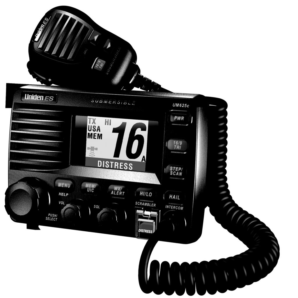
16 A Look at the Radio 13 Light Sensor Used for auto dimming and color pallet changes for night operation PUSH/SELECT - Rotate to tune channels and highlight menu items you want to select, then press to select the channel you tuned or the item you selected. 2. MENU/HELP - Press to use the menu for the DSC Call, and Fog Horn. Hold down for 2 seconds to use the radio s help function. 3. VOL - Rotate to adjust the volume. 4. MEM/UIC - Press to add to, or delete from the scan memory, the currently-tuned channel. Hold down for 2 seconds to change the channel's mode (USA/CAN/INT). 5. SQL - Rotate to adjust the squelch. 6. WX/ALERT - Press to listen to the active weather channel in your area. The radio automatically tunes to the active weather channel which it finds first. The weather channel's channel number appears on the display. Hold down for 2 seconds to set the radio to the weather alert mode (see Using the Weather Function on Page 23). 7. HI/LO/SCRAMBLER - Press to change the radio's output power. Hold down for 2 seconds to turn on the optional scrambler feature (see Using the Scrambler on Page 23). 8. DISTRESS - Lift the protective tab then hold down for 5 seconds to send a distress call (see Sending a DSC Distress Call on Page 24). 9. HAIL/INTERCOM - Press to turn on one or both hailers (see Using Hail on Page 20). Hold down for 2 seconds to use the radio's intercom feature (see Using the Intercom on Page 20). 10. STEP/SCAN - Repeatedly press to step through each channel in memory. Hold down for 2 seconds to use the radio's channel scan feature (see Scanning Memory Channels on Page 22) /9 TRI - Press once to quickly tune to Coast Guard/Distress/Hailing Channel 16. Press again to quickly tune to Coast Guard/Distress/Hailing Channel 9. Press again to quickly tune to the previously-tuned channel. Hold down for 2 seconds to set the radio to the Triple Watch mode (see Using Triple Watch on Page 22). 12. PWR - Press to turn the radio on or off. 16 Setting Up The Radio
17 A Look at the Microphone PTT PTT - Press to send a transmission. Release to hear a transmission. / - Repeatedly press to tune channels and select menu items. 16/9 TRI - Press once to quickly tune to Coast Guard/Distress Channel 16. Press again to quickly tune to the secondary Hailing Channel 9. Press again to quickly tune to the previouslytuned channel. Press and hold to activate TRI Watch Channels 16/9 and the working channel. A Look At the Display (1) (2) (3) (4) You can access each of the main screens by applying power, waiting about 4 seconds, then pressing the PUSH/SELECT control once to reach the menu selector screen. Rotate the PUSH/SELECT control until you see the desired screen highlighted. Then press the control to bring up the screen. The examples shown presume that you have connected an optional GPS unit. The RADIO screen (1) displays the selected channel and the channel name as well as other data you can select during setup. In this example, channel 16 is the Coast Guard/Distress/Hailing channel. The XTRACK screen (2) displays direction, and bearing as well as Estimated Time Enroute if you have received a Distress, a position send from another vessel, or a position reply. The scale at the bottom is a guide to how far off course you might be. If the MMSI you receive has an associated name in your Directory, that name is automatically displayed. The COMPASS screen (3) dynamically shows your heading and bearing. It is easily read rapidly as a convenience. The DIGITAL screen (4) displays basic data regarding your vessel s movement, direction, ETE, and distance. You can display a fifth screen (5) that is similar to screen 4 starting from the RADIO screen. Press and hold the PUSH/SELECT control for approximately 2 seconds. The screen to the right appears. To return to the RADIO screen, press and release the PUSH/SELECT control. (5) A Look at the Display 17
18 Basic Operation Turning the Radio On and Off Press PWR to turn on the radio. The radio sounds a tone and a screen showing the user MMSI appears if previously set. If you have not set a user MMSI, see Setting Up a User MMSI on Page 34. Note:If the radio is turned on for at least 3 seconds after you select a channel, it remembers the last channel you tuned when you turn it off. Press PWR again to turn off the radio. Selecting a Channel Rotate PUSH/SELECT to select a channel. Rotating PUSH/SELECT clockwise tunes forward through the channels, while rotating PUSH/SELECT counterclockwise tunes backward through the channels. The currently-tuned channel appears on the display. If the radio is set to marine mode, channel numbers appear as two digits. If the radio is set to WX mode, channel numbers appear as one digit. Note: If A appears next to a channel number, this indicates the channel is in a simplex mode on the ship station transmit side of an international duplex channel. Transmitting and Receiving To transmit, hold down PTT on the microphone. TX appears on the display. Release PTT to receive. TX disappears. Notes: If the channel is set to transmit at low power, you can change it to transmit at high power by pressing HI/LO/SCRAMBLER. If you are attempting to transmit on a normally power restricted channel while transmitting, press HI/LO/SCRAMBLER while holding down the PTT switch to overide the restriction. No other key except HI/LO/SCRAMBLER works. If you transmit continuously for longer than 5 minutes, TX and the channel number blink and the radio stops transmitting. This warns you that PTT might be stuck. To resume transmitting, release PTT then press it again. The radio cannot transmit on Channel 15 (USA). If you hold down PTT while turning on the radio, the radio sounds an error tone and TX and the channel number blink. No key except HI/LO/SCRAMBLER works. You cannot transmit while the radio is set to WX mode or Scan mode. If you press PTT while the radio is set to Scan mode, the radio cancels that mode but does not transmit. The radio cannot transmit voice data on Channel 70. Only DSC data such as a Distress Call can be transmitted on Channel Basic Operation
19 Adjusting the Transmit Power Press HI/LO/SCRAMBLER to adjust the transmit power. If the transmit power on the currently tuned channel is set to Hi (25W), pressing HI/LO/SCRAMBLER changes it to Lo (1W), and LO appears on the display. If the transmit power on the currently tuned channel is set to Lo, pressing HI/LO/SCRAMBLER changes it to Hi, and HI appears. Important: The radio automatically sets itself to low transmit power if you tune to Channels 13, 67, 75, 76, 77 based on FCC rules. You cannot change the transmit power to high on Channel 75 or Channel 76. You can, in an emergency, overide the default setting on Channel 13 or Channel 67. Press Hi/LO/SCRAMBLER while holding in the PTT switch to switch to high. Notes: You cannot change the transmit power while the radio is set to Scan mode. The radio automatically sets itself to high transmit power if you use PUSH/SELECT to tune to Channel 16, press 16/9 TRI, or it receives a distress call. The radio sets itself back to low power if you use PUSH/SELECT to select another channel. Using Scan Note: If you hold down STEP/SCAN while the radio is set to WX mode or Coast Guard/ Distress/Hailing mode, it cancels that mode and starts memory channel scanning. Using Triple Watch Scan Triple Watch lets you easily scan emergency channels along with a channel you select. To use Triple Watch scan, hold down STEP/SCAN for about 2 seconds. The radio scans Channel 16, Channel 9, and the current memory channel. TRI appears on the display. Using Normal Scan Normal scan lets you quickly scan and tune only selected channels. To use normal scan, set the radio to Triple Watch scan then hold down 16/9 TRI for about 2 seconds. The radio scans any channels you saved in memory and SCANNING appears. Notes: If you use normal scan, the radio scans all channels except emergency channels. Use Triple Watch scan (see Using Triple Watch Scan) to scan emergency channels. You must save at least two or more channels in the radio's memory to use memory scan. See Saving Channels in Memory on Page 22 for more information. Using All Channel Scan In RADIO SETUP, set CHANNEL SCAN to ALL CH. Then, press and hold 16/9/TR for 2 seconds during a Triple Watch scan setting. All channels are scanned except Emergency 16 and Emergency 9. Basic Operation 19
20 Using Step Step lets you quickly tune through the channels you saved in the radio's memory. To use step, repeatedly press STEP/SCAN. The radio tunes a channel you stored in memory each time you press STEP/SCAN. Using Hail Note: You must connect one or two optional hailer horns to the radio to use the hail feature. To enable the hail feature, press HAIL/INTERCOM. A selection screen appears. Then select the hailer you want to use (Hailer 1, Hailer 2, or both ) then press PUSH/SELECT to select it. Next, press PTT to speak. TALK appears. Release PTT to listen. LISTENÿ appears. You hear any response to your hail through the radio's speaker. To adjust the hail outgoing volume, repeatedly press or on the microphone or rotate PUSH/SELECT on the radio. To exit hail, press HAIL/INTERCOM again. Using the Intercom The intercom feature lets you call optional WHAM x 4 microphones connected to the radio. You can select and call one microphone, or individually add each of several microphones to a temporary group using the Intercom Menu, or each microphone connected to the radio. Notes: You cannot use a WHAM wireless microphone to use the intercom. WHAM x 4 microphone users can also call each other and the radio. If the WHAM x 4 microphone user cannot connect with the radio, the intercom feature does not work and the radio sounds an error tone. Intercom mode is cancelled if 16/9 TRI or DISTRESS is pressed. Follow these steps to use the intercom. 1. Hold down HAIL/INTERCOM for about 2 seconds. 2. Follow one of these steps to select one or all WHAM x 4 microphones connected. a. To select one WHAM x 4 microphone, rotate PUSH/SELECT until the WHAM x 4 microphone you want to talk to is highlighted on the INTERCOM screen then press PUSH/ SELECT to select it. b. To create a temporary group of WHAM x 4 microphones, rotate PUSH/SELECT and select each mic listed. Rotate PUSH/SELECT and press the knob to add it to the group. A check icon appears for that mic. c. To select all the connected mics, rotate the PUSH/SELECT until ALL is highlighted. Press the knob to select all the mics. d. To call each microphone instead of all, rotate PUSH/SELECT to select CALL, then press PUSH/SELECT to select that mic. A check icon appears next to the selected mic on the radio s display and each selected microphone sounds an audible tone. When you select CALL and press PUSH/SELECT, you call another checked WHAM x 4 mic. 20 Basic Operation
21 Notes: Only those WHAM x 4 microphones or sub radios with which the radio can communicate appear on the display. Only one pair of WHAM x 4 mics can be on the intercom unless you make a group or select all. No person in the group can hear the MRN signal except the main radio. If a DCS signal is received, or if 16/9/TRI is pressed, the Intercom mode reverts to Radio mode. A connected WHAM x 4 cannot change either the base or sub radio remotely. A connected WHAM x 4 unit cannot cancel INTERCOM mode remotely. To exit intercom, hold down HAIL/INTERCOM for about 2 seconds. Using GPS Connect an external GPS unit to the NMEA0183 connection. The GPS unit then displays data and the UM625c displays its information in white to confirm valid data. If no valid data is represent, the information is displayed in red. To change to the GPS mode, press and hold PUSH/SELECT for 2 seconds. Date, time, speed, heading, latitude, and longitude are displayed. To change back to normal model, press and hold PUSH/SELECT for 2 seconds again. Note: If the radio fails to receive valid GPS data, no change is displayed on the radio. The local UTC time offset is automatically applied based on longitude and latitude data. It also takes into account the International Date Line. You can also adjust the time by TIME ADJUST and DAYLIGHT SAV. If no valid GPS data is present, any GPS information is displayed in red. Using Battery Hi/Lo Detect The radio automatically alerts you if the connected battery is providing too much or not enough voltage. If the battery is providing more than 16 volts, CHECK BATTERY HIGH VOLTAGE appears. If the battery is providing less than 11 volts, CHECK BATTERY LOW VOLTAGE appears. Press any key to delete the message temporarily. If the condition continues, the message returns. Using 16/9 TRI Press 16/9 TRI once to quickly tune the radio to Channel 16. Press 16/9 TRI again to quickly tune the radio to Channel 9. Press 16/9 TRI a third time to quickly retune the radio to the previous channel. Notes: Pressing 16/9 TRI cancels WX mode if the radio is set to WX mode. Basic Operation 21
22 Pressing 16/9 TRI stops the radio from scanning if the radio is set to Scan mode. The radio cancels Coast Guard/Distress/Hailing mode if you press WX, MENU/HELP, HAIL/INTERCOM, or STEP/SCAN, hold down STEP/SCAN or HAIL/INTERCOM, or rotate PUSH/SELECT. Using Memory Channel Saving Channels in Memory You can save channels you tune into the radio's memory. This makes it easy to quickly tune the channels again. To save a channel, tune to the channel then press MEM/UIC to save it. MEM appears. To delete a channel from memory, tune to the channel then press MEM/UIC. MEM disappears. Notes: You cannot save a memory channel while in WX mode. You must store more than one channel in the memory for the memory channel scan to work. Scanning Memory Channels You can scan channels you saved in the radio's memory. This lets you quickly access and tune them. To scan memory channels, hold down STEP/SCAN for about 2 seconds. SCANNING appears. If the radio detects a transmission on a scanned channel, the channel number blinks. The radio waits 3 seconds after the transmission ends then resumes scanning. To stop scanning, hold down STEP/SCAN for about 2 seconds or press PTT. Notes: Rotating PUSH/SELECT clockwise resumes scanning if the radio stopped on a transmission. Pressing DISTRESS also stops the radio from scanning. Using Triple Watch Triple Watch scans the selected working channel. Then, every 2 seconds, it moves to Channel 16 then Channel 9 in that order. If the radio detects a transmission on Channel 9 or Channel 16 while set to Triple Watch, the channel indicator blinks and the radio stops scanning for 2 seconds while you listen to that active channel. Hold down 16/9 TRI about 2 seconds to turn Triple Watch on or off. If Triple Watch is off, TRI appears and Triple Watch is enabled. If Triple Watch is on, TRI disappears and Triple Watch is disabled. Notes: If Channel 9 is busy, the radio scans Coast Guard/Distress/Hailing Channel 9 and Coast Guard/Distress/Hailing Channel 16 in turn. If you turn on Triple Watch and Channel 16 is busy, the radio receives Coast Guard/ Distress/Hailing Channel Basic Operation
23 If you turn on Triple Watch while the radio is set to Coast Guard/Distress/Hailing mode, the radio scans primary Coast Guard/Distress/Hailing Channel 16, secondary Coast Guard/ Distress/Hailing Channel 9, and the last marine channel (Channel 16 or Channel 9). If you turn on Triple Watch while the radio is set to WX mode, the radio scans primary Coast Guard/Distress/Hailing Channel 16, secondary Coast Guard/Distress/Hailing Channel 9, and the WX channel. Triple Watch resumes if the signal of the channel you tuned is lost for 3 seconds. If the radio is scanning Coast Guard/Distress/Hailing Channel 9 or 16, the CH indicator changes. Using the Scrambler The radio's optional scrambler makes voice transmissions unintelligible to other radios without a scrambler or that are scrambler equipped but not set to the same scrambler code. The radio descrambles incoming scrambled voice transmissions if the transmitting radio is set to the same scrambler code. If the scrambler is turned on, the radio can communicate only with other radios set to the same scrambler code. You must install an optional scrambler board in the radio and set a scrambler code (see Setting a Scrambler Code on Page 43) to use the scrambler. Note: You cannot enable scrambling using a WHAM microphone. Hold down HI/LO/SCRAMBLER for 2 seconds to turn on the scrambler. SCRAM appears on the display. To turn off the scrambler, hold down HI/LO/SCRAMBLER for 2 seconds. SCRAM disappears. Using the Weather Function The FCC (Federal Communications Commission) has allocated channels for use by the National Oceanic and Atmospheric Administration (NOAA). Regulatory agencies in other countries have also allocated channels for use by their weather reporting authorities. NOAA and your local weather reporting authority broadcast your local forecast and regional weather information on one or more of these channels. To hear your local forecast and regional weather information, press WX/ALERT. Your radio scans through the weather band then stops on the first active weather frequency, and WX appears on the display. Rotate PUSH/ SELECT to select another weather channel. To stop listening to the weather broadcast, press WX/ALERT again. The radio returns to the last channel you tuned before you selected the weather channel. Using Weather Alert To set the radio so it alerts you if it receives a weather alert, hold down WX/ALERT for 2 seconds. If the radio receives a weather alert, it sounds a tone. Press any key to listen to the weather broadcast. To turn off weather alert, hold down WX/ALERT for 2 seconds. Note: You cannot listen to weather broadcasts while the weather alert mode is active. Basic Operation 23
24 Using SAME Alert The National Weather Service precedes each weather alert with a digitally encoded SAME (Specific Area Message Encoding) signal, then a 1050 Hz tone. The SAME signal includes a FIPS (Federal Information Processing Standard) area code, and an event code that corresponds with the type of alert being sent. You can configure your radio to operate in SAME Standby mode, where it monitors a selected weather radio station for SAME alerts for areas you specify. You can program your radio with up to 30 FIPS codes for the areas you desire. The National Weather Service maintains a current list of FIPS codes at If the radio receives a SAME alert tone, it checks the tone against any FIPS codes you stored (see Setting FIPS Codes on Page 38 for more information). If the radio finds a match, it sounds a tone. Press any key to turn off the tone Performing a Radio Self Test Selecting this menu item performs a complete self test on the radio. The self test provides the following information. Hail Speaker Condition (Connect or Not Connected) GPS Condition (OK, Not Connected, No Data Flow, Sentences Not Supported) Battery Condition (OK,Voltage Too Low, Voltage Too High) To run the self test, select SELF TEST then press PUSH/SELECT. A screen appears showing the condition of each tested item. If X appears next to the item, the item did not pass the test. For more information about items that did not pass the test, rotate PUSH/SELECT to select the item, then press PUSH/SELECT to select it. DSC Operation Sending a DSC Distress Call Important: Never test your radio s distress feature under any circumstances. It is unlawful to send a false distress signal even for testing purposes. Your radio s distress feature lets you send a distress call using maximum (HI) power. 1. Lift the clear plastic protective tab over DISTRESS. If you momentarily press DISTRESS, the channel you were on at the time immediately changes to 16 and your power level changes to HI. If you hold down DISTRESS the radio beeps once per second. At the end of 5 seconds, a condition screen appears listing several distress condition choices. Rotate PUSH/SELECT to choose the appropriate distress condition or EXIT if you want to cancel. 2. If you have chosen the correct distress condition and you want to proceed, press PUSH/ SELECT. The distress call is sent immediately. To cancel sending the call, rotate PUSH/ SELECT to CANCEL and press the knob. 24 DSC Operation
25 3. Once sent, the radio monitors transmission between CH 16 and CH 70. until it receives an acknowledgement signal (ACK) 4. The radio sounds an alert which lasts between 210 and 270 seconds. The sound ceases upon receipt of an ACK. Notes: If your radio receives a DSC call from another radio, any message on your screen is replaced with the new one. If you press any key while there is a message displayed, the message disappears. The alert tone starts at a reduced volume and gradually becomes louder, reaching a maximum level after 10 seconds. The DCS tone for Routine or Distress stop automatically after 2 minutes when STANDBY mode is OFF. The Routine tone stops after 5 seconds while the Distress tone stops after 30 seconds when STANDBY is ON. When the radio receives a DSC call, it takes priority and all other modes/functions such as SCAN, TRIPLE WATCH, WX, WX ALERT and EMG are cancelled. Receiving a DSC Distress Call If the radio receives a DSC distress call, it sounds a distress tone up to 2 minutes. If the name of the vessel sending the distress call is programmed into the radio, the vessel s name appears. Otherwise, the vessel s MMSI, position, time, and the nature of their distress appear. The Radio Menu Settings for DSC Call and Fog Horn To enter settings for DSC CALL and FOG HORN options, press MENU/HELP while the radio is tuned to a frequency. A RADIO MENU screen appears listing DSC CALL, FOG HORN and EXIT. Rotate PUSH/SELECT to highlight the desired item, then press PUSH/SELECT to select it. Unless you have no Fog Horn connected, you see several optional setting that you can make for each item. Without a Fog Horn connected, you see HORN IS NOT CONNECTED. To return to the previous menu, press MENU/HELP. To exit, rotate PUSH/SELECT to select EXIT then press PUSH/SELECT. The following chart shows the radio menu options with a Fog Horn connected. Basic Operation 25
26 DSC CALL - Lets you select and work with DSC Call options. See Using the DSC Call Menu. RADIO MENU DSC CALL FOG HORN FOG HORN - Lets you select and work with fog horn options. See Setting the Fog Horn Options on Page 31. Using the DSC Call Menu The radio's DSC Call feature lets you transmit and receive DSC Calls based on ITU-R M For a detailed discussion, see ITU%20DSC%20tech%20spec.pdf on line. The radio supports the following DSC calls. To select the DSC Call menu, press MENU/HELP then rotate PUSH/SELECT to select DSC CALL. Then press PUSH/SELECT to select it. The following choices appear: INDIVIDUAL GROUP ALL SHIPS POS REQUEST POS SEND DSC STANDBY RECEIVE LOG DIRECTORY MANUAL UNDERWAY STOP SAIL UNDER TOW ANCHOR AGROUND YELP Using DSC Individual Call DSC CALL MENU INDIVIDUAL GROUP ALL SHIPS POS REQUEST POS SEND DSC STANDBY RECEIVE LOG DIRECTORY EXIT DSC individual call lets you transmit DSC calls to an individual station. You can also receive DSC calls from other stations.the radio automatically sets itself to high power when it sends a DSC individual call. 1. Rotate PUSH/SELECT to select INDIVIDUAL, then press PUSH/SELECT to select the station. A screen showing the stations saved in the directory appears. 2. Follow one of these steps to select the station where you want to send a DSC call. 26 The Radio Menu Options
UT01920ZZ_1 4/7/04 2:19 PM Page 1
 UT01920ZZ_1 4/7/04 2:19 PM Page 1 UT01920ZZ_1 4/7/04 2:19 PM Page 2 Maritime Radio Services Operation Warning! This transmitter will operate on channels/frequencies that have restricted use in the United
VHF 300 Series. owner s manual
 VHF 300 Series owner s manual VHF 300 Series Owner s Manual Introduction Introduction The VHF 300 series radios equip you with the ability to communicate on all International, USA, and Canadian marine
UM455 VHF DSC Marine Radio
 UM455 VHF DSC Marine Radio For more exciting new products please visit our website: Australia: www.uniden.com.au Making a distress call NOTE: There is no official VHF DSC shore infrastructure in Australia.
VHF585 CLASS D MARINE RADIO MODEL (BLACK) / (WHITE) Owner s Manual
 / (WHITE) Owner s Manual") VHF585 CLASS D MARINE RADIO MODEL 16230534 (BLACK) / 16230542 (WHITE) Owner s Manual MAKING A DISTRESS CALL Lift the red cover. Press and hold the DISTRESS button for three seconds. Your radio transmits
VHF585 CLASS D MARINE RADIO MODEL 16230534 (BLACK) / 16230542 (WHITE) Owner s Manual MAKING A DISTRESS CALL Lift the red cover. Press and hold the DISTRESS button for three seconds. Your radio transmits
VHF 110/210 AIS Series. Owner s Manual
 VHF 110/210 AIS Series Owner s Manual 2017 Garmin Ltd. or its subsidiaries All rights reserved. Under the copyright laws, this manual may not be copied, in whole or in part, without the written consent
VHF 110/210 AIS Series. Owner s Manual
 VHF 110/210 AIS Series Owner s Manual Table of Contents Introduction...1 Radio Overview... 1 Handset Overview... 1 Home Screen... 1 System Status Icons... 1 Basic Operation... 2 Turning On and Off the
VHF 115/215 AIS SERIES. Owner s Manual
 VHF 115/215 AIS SERIES Owner s Manual 2018 Garmin Ltd. or its subsidiaries All rights reserved. Under the copyright laws, this manual may not be copied, in whole or in part, without the written consent
Explorer 725 / 705. VHF Marine Radio Quickstart Guide.
 Explorer 725 / 705 VHF Marine Radio Quickstart Guide www.northstarnav.com This Quickstart Guide is to be used with the Northstar Explorer 721 VHF Radio Installation and Operation Manual. The Explorer 721
VHF 100/200 Series. owner s manual USA DISTRESS. Š.Œ ƒ ˆ Š Œ. ˆ : ŒPM UTC WATCH PA SCAN 25W LOCAL
 VHF 100/200 Series owner s manual 25W 16 DISTRESS LOCAL WATCH PA SCAN USA Š.Œ ƒ ˆ Š Œ. ˆ : ŒPM UTC 2008 Garmin Ltd. or its subsidiaries Garmin International, Inc. 1200 East 151st Street, Olathe, Kansas
MC-8050 DSC. owner s Manual
 MC-8050 DSC owner s Manual MAkInG A DIstRess CALL Lift the red cover. Press and hold the DIstRess button for three seconds. Your radio transmits your boat s location every few minutes until you receive
HM-162B/SW. z HM-162B/SW supplied accessories. x Function display INSTRUCTIONS REMOTE-CONTROL MICROPHONE
 INSTRUCTIONS REMOTE-CONTROL MICROPHONE HM-162B/SW Thank you for purchasing the HM-162B/SW REMOTE- CONTROL MICROPHONE. The COMMANDMIC III TM is a remote control microphone for use with the IC-M604 or else.
UM355 VHF Marine Radio
 UM355 VHF Marine Radio For more exciting new products please visit our website: Australia: www.uniden.com.au Making a distress call Making a DISTRESS Call Speak slowly - clearly - calmly. For future reference,
MC 1010 VHF Marine Radio Operating Guide
 MC 1010 VHF Marine Radio Operating Guide Thu Jan 28 14:42:49 1999 Maritime Radio Services Operation Warning! This transmitter will operate on channels/ frequencies that have restricted use in the United
UM415 SUBMERSIBLE DSC MARINE RADIO RADIO MARITIME ASN OWNER S MANUAL GUIDE D UTILISATION
 UM415 SUBMERSIBLE DSC MARINE RADIO RADIO MARITIME ASN OWNER S MANUAL GUIDE D UTILISATION Making a Distress Call Lift the red cover. Press and hold the DISTRESS button for three seconds. Your radio transmits
VHF 7000, 7100US, 7100EU. Operation Manual NAVMAN
 VHF 7000, 7100US, 7100EU Operation Manual w w w. n a v m a n. c o m NAVMAN FCC Statement This equipment has been tested and found to comply with the limits for a Class B digital device, pursuant to Part
HM-162E. z HM-162E supplied accessories. x Function display INSTRUCTIONS REMOTE-CONTROL MICROPHONE. Thank you for purchasing the HM-162E REMOTE- q w e
 INSTRUCTIONS REMOTE-CONTROL MICROPHONE HM-162E Thank you for purchasing the HM-162E REMOTE- CONTROL MICROPHONE. The COMMANDMIC III TM is a remote control microphone for use with the IC-M603 or else. Please
Maritime Radio Services Operation
 LTD1025 Maritime Radio Services Operation Warning! This transmitter will operate on channels/ frequencies that have restricted use in the United States. The channel assignments include frequencies assigned
INSTRUCTION MANUAL. VHF MARINE TRANSCEIVER ic- m59
 INSTRUCTION MANUAL VHF MARINE TRANSCEIVER ic- m59 IN CASE OF EMERGENCY If your vessel requires assistance, contact other vessels and the Coast Guard by sending a distress call on channel 16. Or, transmit
RAY230E European Version
 RAY230E European Version The RAY230E is a VHF radiotelephone that includes equipment for Class D Digital Selective Calling. It is intended for general communication within the Maritime Mobile Service worldwide
GX600D VHF MARINE RADIO INSTRUCTION MANUAL PRINTED IN ENGLISH INTERNATIONAL: 0168! USA : FCC ID : TXJGX600D CANADA : IC 7332A-GX600D AUSTRALIA:
 GX600D VHF MARINE RADIO INSTRUCTION MANUAL PRINTED IN ENGLISH INTERNATIONAL: 0168! USA : FCC ID : TXJGX600D CANADA : IC 7332A-GX600D AUSTRALIA: WARNING: SAFETY INFORMATION The GX600D is a radio transmitting
RMV25 / RMV50 RMU25 / RMU45
 RMV25 / RMV50 RMU25 / RMU45 Owner's Manual TABLE OF CONTENTS INTRODUCTION... 3 FCC Requirements... 3 SAFETY WARNING INFORMATION... 3 CONTROLS and INDICATORS... 5 FRONT PANEL... 5 LCD Icons and Indicators...
Horizon GX2335S NOVA+ 25 Watts VHF/FM Marine Transceiver Owner s Manual
 Horizon GX2335S NOVA+ 25 Watts VHF/FM Marine Transceiver Owner s Manual USA HI SQL VOL HOLD ON/OFF WX SCAN IC U I C SCMB CALL A/B MEM LAMP H/L GX2335S Owner s Manual page 31 TABLE OF CONTENTS FCC NOTICE...
INSTRUCTION MANUAL VHF MARINE TRANSCEIVER. im422
 INSTRUCTION MANUAL VHF MARINE TRANSCEIVER im422 FOREWORD Thank you for purchasing this Icom product. The IC-M422 VHF MARINE TRANSCEIVERS are designed and built with Icom s state of the art technology and
Explorer 710 VHF VHF Marine Radio Operation and Installation Manual
 Explorer 710 VHF VHF Marine Radio Operation and Installation Manual www.northstarnav.com IMPORTANT SAFETY INFORMATION Please read carefully before installation and use. This is the safety alert symbol.
INSTRUCTION MANUAL VHF MARINE TRANSCEIVER. ic- m59euro PWR/VOL VHF MARINE OFF SQUELCH CLR DUAL SCAN DIM ALL
 INSTRUCTION MANUAL VHF MARINE TRANSCEIVER ic- m59euro VHF MARINE PWR/VOL SCAN DIM HI/LO TRI DUAL DIAL CLR ALL C 16 OFF SQUELCH IN CASE OF EMERGENCY If your vessel requires assistance, contact other vessels
FOR MORE INFORMATION ON GMDSS CONTACT:
 FOR MORE INFORMATION ON GMDSS CONTACT: Commanding Officer USCG Navigation Center, MS 7310, 7323 Telegraph Road, Alexandria, VA 20598-7310 Tel:1-703-313-5900 www.navcen.uscg.gov Commandant (CG-652) Spectrum
ECLIPSE DSC GX1000S. Owner's Manual. 25 Watt VHF/FM DSC Marine Transceiver
 ECLIPSE DSC 25 Watt VHF/FM DSC Marine Transceiver Owner's Manual Affordable Ultra Compact Fixed Mount VHF radio Submersible IPX7 Front Panel SC-101 DSC (Digital Selective Calling) with Position Report
QUANTUM GX5500S. Owner's Manual. 25 Watt VHF/FM Marine Transceiver
 QUANTUM 25 Watt VHF/FM Marine Transceiver Owner's Manual Commercial Grade ITU Class D DSC Transceiver Superior Receiver Performance (80 db rejection) 30W Loud Hailer complete with Listen Back and 4 Fog
Controls and Indicators
 CONTENTS Controls and Indicators.... Foldout Introduction............. 2 Features............. 2 Technical Support and Service.. 2 Maritime Radio Services Operation........ 3 Included with Your HH940.....
INSTRUCTION MANUAL VHF FM TRANSCEIVER TK-6110 B (K,K2)
") INSTRUCTION MANUAL VHF FM TRANSCEIVER TK-6110 B62-1216-20 (K,K2) 09 08 07 06 05 04 03 02 THANK YOU! We are grateful you chose KENWOOD for your land mobile applications. We believe this easy-to-use transceiver
INSTRUCTION MANUAL VHF FM TRANSCEIVER TK-6110 B62-1216-20 (K,K2) 09 08 07 06 05 04 03 02 THANK YOU! We are grateful you chose KENWOOD for your land mobile applications. We believe this easy-to-use transceiver
Link-5 VHF. User Guide ENGLISH. lowrance.com
 Link-5 VHF User Guide ENGLISH lowrance.com Copyright 2012 Navico All rights reserved. Lowrance is a registered trademark of Navico No part of this manual may be copied, reproduced, republished, transmitted
Service Manual for RT-2500
 Service Manual for RT-2500 Japan Marina Co., Ltd. 動作仕様書 (OPERATIONSPECIFICATION) BUYER'SMODELNo. :RT-2500 UNIDENNo. :UT605Z VERSIONNo. :1.04 ISSUEDDATE : 05/02/10 CATEGORY :MRN NAME :M.SUZUKI/T.KOGURE
Ray215e. VHF Radio. Owner's Handbook
 Ray215e VHF Radio Owner's Handbook RAY215E Modular VHF Radio Owner s Handbook Document number: R49018_2 Date: April 2002 Purpose RAY215E This handbook contains very important information on the installation,
NAVMAN VHF 7000 / VHF 7100 Owner s Manual
 NAVMAN VHF 7000 / VHF 7100 Owner s Manual 1 FCC Statement This equipment has been tested and found to comply with the limits for a Class B digital device, pursuant to Part 15 of FCC Rules. These limits
TX4400 UHF CB RADIO INSTRUCTION MANUAL TX4400 INSTRUCTION MANUAL PAGE 1
 TX4400 UHF CB RADIO INSTRUCTION MANUAL TX4400 INSTRUCTION MANUAL PAGE 1 TABLE OF CONTENTS GENERAL................................... 3 FEATURES.................................. 3 BASIC OPERATION...4 Front
MobileRadio. Owner'sManual
 EMH MobileRadio Owner'sManual TABLE OF CONTENTS Introduction... 1 Basic Operation... 2 Code Guard Operation... 3 EMH Radio Controls... 4 Button Functions... 4 Built-in Features... 7 Keypad Microphone Operation...
QUANTUM GX5000S. Owner's Manual. 25 Watt VHF/FM Marine Transceiver
 QUANTUM 25 Watt VHF/FM Marine Transceiver Owner's Manual Commercial Grade ITU Class D DSC Transceiver Superior Receiver Performance (80 db rejection) 30 W Loud Hailer complete with Listen Back and 4 Fog
QUANTUM Series GX3500S
 QUANTUM Series 25 Watt VHF/FM ITU Class D DSC Marine Transceiver Owner's Manual Oversized alphanumeric LCD, knobs and keys 30 W Loud Hailer with listen back and 4 fog horns, Bells & Whistles Direct keypad
Standard Operating Procedures for: VHF Marine Radio
 Serenity Houseboat I. Overview Standard Operating Procedures for: VHF Marine Radio VHF, or Very High Frequency, marine radio is the standard method of communication between vessels. Marine radio equipment
Pub LVR-250. VHF Radio. Installation and Operation Instructions
 Pub. 988-0158-051 www.lowrance.com LVR-250 VHF Radio Installation and Operation Instructions Copyright 2007 Navico All rights reserved. Lowrance is a registered trademark of Navico No part of this manual
Ray49E Marine VHF Radio Owner s Handbook. Document number: Date: June 2007
 Ray49E Marine VHF Radio Owner s Handbook Document number: 81297-1 Date: June 2007 3 Contents Trademarks and registered trademarks... 2 About this Handbook...9 Intended Use... 9 Conventions Used... 9 Technical
DC-1122 Compact 5W UHF CB Radio
 DC-1122 Compact 5W UHF CB Radio Instruction Manual Introduction! NOTE Use of the citizen band radio service is licensed in Australia by ACMA Radio communications (Citizen Band Radio Stations) Class Licence
MR F45-D. Our Thanks To You
 Introduction Our Thanks To You Owner s Manual Thank you for purchasing a CobraMarine VHF radio. Properly used, this Cobra product will give you many years of reliable service. How Your CobraMarine VHF
Congratulations on selecting the MRM400 TM from RCA Communications Systems - The Most Trusted Name In Radio!
 1 Congratulations on selecting the MRM400 TM from RCA Communications Systems - The Most Trusted Name In Radio! Our new series of business communications products establishes a new benchmark in premium
Cat. No OWNER S MANUAL. HTX-212 Two-Meter Mobile Transceiver. Please read before using this transceiver.
 19-1125.fm Page 1 Tuesday, August 3, 1999 9:47 AM Cat. No. 19-1125 OWNER S MANUAL HTX-212 Two-Meter Mobile Transceiver Please read before using this transceiver. 19-1125.fm Page 2 Tuesday, August 3, 1999
INSTRUCTION MANUAL VHF MARINE TRANSCEIVER. im504
 INSTRUCTION MANUAL VHF MARINE TRANSCEIVER im504 FOREWORD Thank you for purchasing this Icom product. The IC-M504 vhf marine transceiver is designed and built with Icom s state of the art technology and
MXT100. GMRS Radio OWNER S MANUAL. midlandusa.com
 MXT100 GMRS Radio OWNER S MANUAL Welcome to the World of Midland electronics Congratulations on your purchase of a high quality MIDLAND product. Your 2-way radio represents state-of-the-art high-tech engineering.
INSTRUCTION MANUAL VHF MARINE TRANSCEIVER. im504a
 INSTRUCTION MANUAL VHF MARINE TRANSCEIVER im50a FOREWORD Thank you for purchasing this Icom product. The IC-M50A vhf marine transceiver is designed and built with Icom s state of the art technology and
VHF 100/200 Series Radio Installation Instructions
 These installation instructions are for the following VHF radios and handsets: North American Models VHF 100 VHF 200 GHS 10 International Models VHF 100i VHF 200i GHS 10i Compare the contents of this package
NAUTICO1 (NT1) Owner s Guide
 Owner s Guide") N NAUTICO1 (NT1) Owner s Guide www.midlandradio.com TABLE OF CONTENTS. 1 Introduction.. 2 Important Notice, FCC Licensing... 3 LCD Display.. 4 Controls. 5 Battery Installation. 6 Installing the Belt Clip
N NAUTICO1 (NT1) Owner s Guide www.midlandradio.com TABLE OF CONTENTS. 1 Introduction.. 2 Important Notice, FCC Licensing... 3 LCD Display.. 4 Controls. 5 Battery Installation. 6 Installing the Belt Clip
SUMMIT DM MULTI-NET MOBILE RADIO OPERATING MANUAL
 SUMMIT DM MULTI-NET MOBILE RADIO OPERATING MANUAL SAFETY INFORMATION Proper operation of this radio will result in user exposure below the Occupational Safety and Health Act and Federal Communication Commission
PHANTOM Series PS2000
 PHANTOM Series PS2000 25 Watt VHF/FM ITU Class D DSC Marine Transceiver Owner's Manual ITU-R Class D Commercial Grade remote mount VHF Independent channel 70 receiver for continuous DSC watching Capable
Warning! Nickel-Cadmium Battery Pack Warning
 UTZZ01865AZ Warning! The HH940P is waterproof only when both the antenna and the battery are properly attached. Do not operate the transmitter of any radio equipment unless all the Radio Frequency (RF)
TK-D740 TK-D740H TK-D740HV TK-D840 TK-D840H TK-D840HU
 TK-D740 TK-D740H TK-D740HV TK-D840 TK-D840H TK-D840HU VHF DIGITAL TRANSCEIVER UHF DIGITAL TRANSCEIVER USER MANUAL B5A 0925-00/01 Contents PREPARATION... 4 Connecting the power cable... 4 Installing the
im602 INSTRUCTION MANUAL VHF MARINE TRANSCEIVER
 INSTRUCTION MANUAL VHF MARINE TRANSCEIVER im602 This device complies with Part 15 of the FCC rules. Operation is subject to the following two conditions: (1) This device may not cause harmful interference,
Operating Guide SMH 1525DT SMU 4525KT Technology Drive West Melbourne, FL RELM Wireless Corporation. All Rights Reserved CC OG 23
 W I R E L E S S C O R P O R AT I O N Operating Guide 7100 Technology Drive West Melbourne, FL 32904 2000 RELM Wireless Corporation. All Rights Reserved CC OG 23 ULUD01083ZZ RELM WIRELESS CORP. 7100 Technology
INSTRUCTION MANUAL VHF MARINE TRANSCEIVER. im604
 INSTRUCTION MANUAL VHF MARINE TRANSCEIVER im604 i FOREWORD Thank you for purchasing this Icom transceiver. The IC-M604 VHF MARINE TRANSCEIVER is designed and built with Icom s state of the art technology
PROFESSIONAL DIGITAL TWO-WAY RADIO SYSTEM MOTOTRBO DP 3600/DP 3601 DISPLAY PORTABLE QUICK REFERENCE GUIDE
 PROFESSIONAL DIGITAL TWO-WAY RADIO SYSTEM MOTOTRBO DP 3600/DP 3601 DISPLAY PTABLE QUICK REFERENCE GUIDE m DP 3600/3601 Portables Quick Reference Guide Important Safety Information Product Safety and RF
INSTRUCTION MANUAL TX3400 UHF TRANSCEIVER
 INSTRUCTION MANUAL TX3400 UHF TRANSCEIVER CONTENTS Contents................................... 2 Introduction................................ 2 Features.................................... 2 Operation..................................
PM-500 SWF. Owner s Manual
 PM-500 SWF Owner s Manual MAKING A DISTRESS CALL Speak slowly - clearly - calmly. For future reference, write your boat s name & call sign here: 1. Make sure your radio is on. 2. On the radio, press the
MATRIX SERIES GX2000 and GX2100
 MATRIX SERIES GX2000 and GX2100 25 Watt VHF/FM Marine Transceivers Owner's Manual Integrated dual channel AIS (Automatic Identification System) receiver (GX2100) AIS (Automatic Identification System) receiver
GX-1200 GMDSS DSC RADIO SIMULATOR
 GX-1200 GMDSS DSC RADIO SIMULATOR DISCLAIMER THIS IS NOT A 100% REAL SIMULATION OF THE STANDARD HORIZON GX-1200E VHF DSC TRANSCEIVER, AND SHOULD BE USED ONLY AS GENERIC EXAMPLE FOR TRAINING PURPOSES ONLY.
OPERATING GUIDE OPERATING GUIDE FOR IC-F5060/F6060 SERIES BIIS 1200/MDC 1200 SYSTEM/ LTR /IDAS OPERATION
 OPERATING GUIDE OPERATING GUIDE FOR IC-F060/F6060 SERIES BIIS 100/MDC 100 SYSTEM/ LTR /IDAS OPERATION IMPORTANT Thank you for purchasing this Icom transceiver. The BIIS 100/MDC 100 system/ltr /IDAS (Icom
INSTRUCTION MANUAL VHF MARINE TRANSCEIVER im505
 INSTRUCTION MANUAL VHF MARINE TRANSCEIVER im505 i FOREWORD Thank you for purchasing this Icom product. The IC-M505 VHF MARINE TRANSCEIVER is designed and built with Icom s state of the art technology and
INSTRUCTION MANUAL VHF MARINE TRANSCEIVER. im505
 INSTRUCTION MANUAL VHF MARINE TRANSCEIVER im505 i FOREWORD Thank you for purchasing this Icom product. The IC-M505 VHF MARINE TRANSCEIVER is designed and built with Icom s state of the art technology and
Class-D DSC Marine VHF Radio MT-700. Pony Electric Corporation
 Class-D DSC Marine VHF Radio MT-700 Pony Electric Corporation Table of contents About PONY What is MT-700? Features 2008 Pony Electric Corp. All rights reserved 2 PONY About PONY Pony Electric Corp. (PONY)
PROFESSIONAL DIGITAL TWO-WAY RADIO SYSTEM MOTOTRBO XPR SERIES CONNECT PLUS DISPLAY PORTABLE QUICK REFERENCE GUIDE GUIDE DE RÉFÉRENCE RAPIDE.
 PROFESSIONAL DIGITAL TWO-WAY RADIO SYSTEM MOTOTRBO XPR SERIES CONNECT PLUS DISPLAY PTABLE en fr-ca QUICK REFERENCE GUIDE GUIDE DE RÉFÉRENCE RAPIDE m MOTOTRBO Connect Plus XPR Series Digital Portable Radios
YCE13. Dealer PC Programming Software Reference Manual. Attention!
 YCE13 Dealer PC Programming Software Reference Manual Attention! The YCE13 programing software can only be used with HX380/400 firmware version Ver. 2.00 or later. This software is used to program the
INSTRUCTION MANUAL VHF MARINE TRANSCEIVER. im603
 INSTRUCTION MANUAL VHF MARINE TRANSCEIVER im603 FOREWORD Thank you for purchasing this Icom transceiver. The IC- M603 vhf marine transceiver is designed and built with Icom s state of the art technology
Humminbird VHF255S / VHF255SW Operations Manual _A
 Humminbird VHF255S / VHF255SW Operations Manual 531469-1_A THANK YOU! Thank you for choosing Humminbird, America's #1 name in fishfinders. Humminbird has built its reputation by designing and manufacturing
INSTRUCTION MANUAL VHF MARINE TRANSCEIVER. im603
 INSTRUCTION MANUAL VHF MARINE TRANSCEIVER im603 i FOREWORD Thank you for purchasing this Icom transceiver. The IC-M603 VHF MARINE TRANSCEIVER is designed and built with Icom s state of the art technology
TWO-WAY RADIO MODEL CXR925
 Making Life Easier and Safer Owner s Manual Staying in touch with your family and friends is convenient and easy when using your microtalk radio. Some of the many uses you will discover include: Communicating
USER & INSTALLATION MANUAL SAILOR 6216 VHF DSC
 USER & INSTALLATION MANUAL SAILOR 6216 VHF DSC Thrane & Thrane A/S SAILOR 6216 VHF DSC User and installation manual Document number: 98-128825-THR-E Release date: December 18, 2012 Disclaimer Any responsibility
NVR-1000 VHF RADIOTELEPHONE
 NVR-1000 VHF RADIOTELEPHONE USER S MANUAL NEW SUNRISE NOTICE TO USERS - Thanks for your purchasing this product VHF radio telephone. - The copyright of this manual is owned by the manufacturer, NEW SUNRISE
MATRIX SERIES GX2000 and GX2150
 MATRIX SERIES GX2000 and GX2150 25 Watt VHF/FM Marine Transceivers Owner's Manual Integrated dual channel AIS (Automatic Identification System) receiver (GX2150) AIS (Automatic Identification System) receiver
INSTRUCTION MANUAL VHF MARINE TRANSCEIVER. igm651. Ver
 INSTRUCTION MANUAL VHF MARINE TRANSCEIVER igm51 Ver. 1.004 FOREWORD Thank you for purchasing this Icom transceiver. The IC-GM51 vhf marine transceiver is designed and built with Icom s state of the art
QUANTUM GX2360S. Owner's Manual. 25 Watt VHF/FM Marine Transceiver
 QUANTUM 25 Watt VHF/FM Marine Transceiver Owner's Manual Oversized alphanumeric LCD, knobs and keys Large 2.8 inch internal loudspeaker producing louder audio 30 W Loud Hailer with listen back and 4 fog
All Hazards Weather Alert Radio WR-300
 All Hazards Weather Alert Radio WR-300 Owner s Manual Quick Start Instructions: Please see pg. 5 for important buttons and controls. 1. Place 4 AA batteries (not supplied) into the compartment on the underside
JHD905. Owner s Manual JENSEN MUTE DISP AM/FM AUX WB TIMER HEAVY DUTY JENSEN VOL+ AUDIO MENU VOL- SEEK SEEK AM/FM/WB RECEIVER JHD905
 Owner s Manual MUTE DISP AM/FM AUX WB TIMER HEAVY DUTY VOL+ FM TUN AUDIO MENU TUN + VOL- AM/FM/WB RECEIVER 1 2 3 4 5 6 + AUXIN Thank You! Thank you for choosing a Jensen product. We hope you will find
WR120 Owner s Manual Guide du propriétaire Manual de instrucciones
 WR120 Owner s Manual Guide du propriétaire Manual de instrucciones Midland Radio Corporation 5900 Parretta Drive Kansas City, MO 64120 Tel. (816) 241-8500 All Hazards Alert Weather Radio with S.A.M.E Quick
14 CHANNEL FAMILY RADIO SYSTEM MODEL # FR142
 14 CHANNEL FAMILY RADIO SYSTEM MODEL # FR142 2001 Audiovox Electronics Corp., Hauppauge, NY 11788 Printed in China 128-6020 052FR142104 BEFORE OPERATING THIS PRODUCT PLEASE READ THESE INSTRUCTIONS COMPLETELY
SAILOR 6215 VHF DSC. User and installation manual
 SAILOR 6215 VHF DSC User and installation manual SAILOR 6215 VHF DSC User and installation manual Document number: 98-128471-THR-J Release date: October 18, 2018 i Disclaimer Any responsibility or liability
Midland 248XL I NSTRUCTION GUI DE
 Midland 248XL I NSTRUCTION GUI DE INDEX Introduction...2 Function and location of the controls...3 Installation...7 Power supply...7 Installing an antenna...7 How to use your Midland 248XL...8 Frequency
ic-f1020 ic-f2020 INSTRUCTION MANUAL VHF LAND MOBILE RADIO UHF LAND MOBILE RADIO
 INSTRUCTION MANUAL VHF LAND MOBILE RADIO ic-f1020 UHF LAND MOBILE RADIO ic-f2020 This device complies with Part 15 of the FCC Rules. Operation is subject to the condition that this device does not cause
Making Life Easier and Safer
 The Cobra line of quality products includes: CB Radios microtalk Radios Radar/Laser Detectors Safety Alert Traffic Warning Systems Handheld GPS Receivers Mobile GPS Navigation Systems HighGear Accessories
INSTRUCTION MANUAL VHF FM TRANSCEIVER TK-2206 UHF FM TRANSCEIVER TK-3206 B (M,M3 )
") INSTRUCTION MANUAL VHF FM TRANSCEIVER TK-2206 UHF FM TRANSCEIVER TK-3206 B62-1763-00 (M,M3 ) 09 08 07 06 05 04 03 02 01 00 THANK YOU We are grateful you chose KENWOOD for your land mobile radio applications.
INSTRUCTION MANUAL VHF FM TRANSCEIVER TK-2206 UHF FM TRANSCEIVER TK-3206 B62-1763-00 (M,M3 ) 09 08 07 06 05 04 03 02 01 00 THANK YOU We are grateful you chose KENWOOD for your land mobile radio applications.
INSTRUCTION MANUAL VHF FM TRANSCEIVER TK-7102H UHF FM TRANSCEIVER TK-8102H KENWOOD CORPORATION B (M)
") INSTRUCTION MANUAL VHF FM TRANSCEIVER TK-7102H UHF FM TRANSCEIVER TK-8102H KENWOOD CORPORATION B62-1596-00 (M) 09 08 07 06 05 04 03 02 01 00 THANK YOU! We are grateful you chose KENWOOD for your personal
INSTRUCTION MANUAL VHF FM TRANSCEIVER TK-7102H UHF FM TRANSCEIVER TK-8102H KENWOOD CORPORATION B62-1596-00 (M) 09 08 07 06 05 04 03 02 01 00 THANK YOU! We are grateful you chose KENWOOD for your personal
AM/FM 10 METER MOBILE AMATEUR TRANSCEIVER OPERATING MANUAL
 AM/FM 10 METER MOBILE AMATEUR TRANSCEIVER OPERATING MANUAL INTRODUCTION Congratulations on your purchase of a Magnum S-6 AM/FM 10 meter transceiver. Your Magnum S-6 is designed to provide years of enjoyment
Instruction Manual CS800 Mobile Radio
 Instruction Manual CS800 Mobile Radio (This is a revised Version of the CSI Manual. The Information contained was created by Independent Radio Operator. Connect Systems does not have any responsibility
CON NEX HP. OWNER'S MANUAL Full Channel AM/FM Amateur Mobile Transceiver TABLE OF CONTENTS TUNING THE ANTENNA FOR OPTIMUM S.W.R..
 TABLE OF CONTENTS PAGE SPECIFICATIONS... 2 INSTALLATION... 3 LOCATION... 3 CON NEX - 4300HP MOUNTING THE RADIO... 3 IGNITION NOISE INTERFERENCE... 4 ANTENNA... 4 TUNING THE ANTENNA FOR OPTIMUM S.W.R..
User manual AWR-8000 / AWR Advanced Wireless Communications
 User manual AWR-8000 / AWR-8001 Advanced Wireless Communications THANK YOU! Thank you for your purchase of Advanced Wireless Communications AWR-8000 / AWR-8001 two-way radio. This portable two-way radio
OWNER S MANUAL
 OWNER S MANUAL 19-1208 RADIOSHACK CORP. FCC ID : AAO1901208 JOB # : 578ZA1 EXHIBIT # : 6 INTRODUCTION Your Radio Shack 19-1208 Business band transceiver is a portable, easy-to-use, two-way radio that you
Important safety instructions
 RCR-29 GB Version 1 Important safety instructions VERY IMPORTANT PLEASE READ Sangean suggest that you keep your AC Adapter at least 12 inches away from the radio while listening to the AM Band. Your Sangean
User Manual. Specifications...3. Control and Operation Microphone...8. Installation...9. Installation of Main Unit...9
 Contents Specifications...3 Control and Operation...4-7 Microphone...8 Installation...9 Installation of Main Unit...9 Antenna Installation...9 Operational test...9 Frequency Bands Table...10 Frequency
INSTRUCTION MANUAL VHF MARINE TRANSCEIVER. im505
 INSTRUCTION MANUAL VHF MARINE TRANSCEIVER im505 FORWORD Thank you for purchasing this Icom product. The IC-M505 vhf marine transceiver is designed and built with Icom s state of the art technology and
OPERATING GUIDE OPERATING GUIDE FOR IC-F5060/F6060 SERIES BIIS 1200/MDC 1200 SYSTEM/ LTR /IDAS NXDN OPERATION
 OPERATING GUIDE OPERATING GUIDE FOR IC-F060/F6060 SERIES BIIS 100/MDC 100 SYSTEM/ LTR /IDAS NXDN OPERATION IMPORTANT Thank you for purchasing this Icom transceiver. The BIIS 100/MDC 100 system/ltr /IDAS
SAILOR RT4722 VHF-DSC DUPLEX Operating Instructions. Distress Calls, see page ii. Contents, see page 1.
 SAILOR RT4722 VHF-DSC DUPLEX Operating Instructions Distress Calls, see page ii. Contents, see page 1. DISTRESS Call Acknowledgment Quick DISTRESS Call 1. If off or UNIT OFF: press ON/OFF. Distress acknowledgment
OPERATING GUIDE VHF TRANSCEIVER. Iç-G88
 OPERATING GUIDE VHF TRANSCEIVER Iç-G88 INTRODUCTION PREFACE We appreciate you choosing Icom for your communication needs. The MDC 1200 signaling system is built into your IC-G88 vhf transceiver. IMPORTANT
Table of Contents. Quick Start Guide. Important Notes! Nautilus GPS Components. Operation. Region Programming & MMSI. Nautilus GPS App.
 Table of Contents 03 04 05 06 07 08 09 09 10 10 11 Quick Start Guide Important Notes! Nautilus GPS Components Operation Region Programming & MMSI Nautilus GPS App Test Sequence Maintenance Battery Information
VHF Transceiver AR6201
 VHF Transceiver AR6201 Operating Instructions Issue 2 / October 2010 Article No. 0618.764-071 Becker Flugfunkwerk GmbH Baden-Airpark B 108 77836 Rheinmünster Germany Telefon / Telephone +49 (0) 7229 /