Case Study: Inglewood Distribution Automation. April 5 th, 2018 NWESS
|
|
|
- Paulina Stokes
- 5 years ago
- Views:
Transcription

1 Case Study: Inglewood Distribution Automation April 5 th, 2018 NWESS

2 Outline Introduction to Puget Sound Energy (PSE) Distribution Automation Overview Project Implementation DA Scheme Example Adaptive Setting Groups Device Coordination Design Challenges Standardizing Equipment Special Considerations


3 Puget Sound Energy (PSE) PSE is Washington State s oldest and largest utility Served the Puget Sound egion for over 135 years 1.1 million electric customers 400+ substations 300+ distribution substation feeder circuits Primarily a distribution focused electric utility OT ANGELES AM SAN JUAN JEFFESON MASON SHELTON OAK HAO POT TOWNSEND OLYMPIA THUSTON CENTALIA CHEHALIS ANACOTES ISLAND EMETON KITSAP LANGLEY AINIDGE ISLAND GIG HAO ELLINGHAM MOUNT VENON MAYSVILLE EDMONDS SEATTLE TACOMA EVEETT MONOE DUVALL EDMOND ELLEVUE ENTON KENT PUYALLUP AUUN WHATCOM SKAGIT PIECE SNOHOMISH INDEX KING NOTH END LACK DIAMOND ENUMCLAW CHELAN WENATCHEE CLE ELUM KITTITAS ELLENSUG KITTITAS YAKIMA LEWIS YAKIMA


4 Distribution Automation Overview PSE Formed a task force in 2015 for vendor proposals Project benefits estimated at 20x their initial cost Per Project reliability benefits 5,000 Customer Interruptions reduced 700,000 Customer Minutes of Interruption reduced
5 Approaches to Distribution Automation Several Different Approaches to DA Fault Targeting Only Switches Exposes Entire Feeder to momentary outages Little to no coordination study High Speed Communications GOOSE Cost Prohibitive equires new equipment PSE s Hybrid Approach Designing the DA scheme around protection requirements and fundamentals
6 FLIS PSE Protective Devices TU (emote Terminal Unit) EMS (Energy Managemnet System) SCADA Operator Control FLIS Software
7 System One Line KNM #2 23 ING #1 X N.O. X636 X1424 X420 X5408 X1829 N.O. N.O. X76976
8 51P/51G PU Levels KNM #2 PH 720 G 360 ING #1 N.O. PH 400 G 340 NA PH 300 G 300 PH 720 G 360 PH 400 G 340 PH 720 G 360 PH 300 G 300 NA N.O. N.O. PH 400 G 340
9 Typical Distribution Time Current Curves 10 TIME (SECONDS) Fault Current 1 Damage Curve Fuse Curves ΔCTI CUENT (AMPEES) 0.1k 1k 10k Transformer reaker ecloser 1 ecloser 2
10 Line Lengths KNM #2 ING # mi 1.35 mi 0.5 mi mi Z L mi 1.4 mi 1.45 mi 0.6 mi 1.5 mi
11 Adaptive Setting Group Example - Fault KNM #2 ING #1
12 Adaptive Setting Group Example - Fault KNM #2 EMS FLIS (DA) EMS ING #1 ECLOSE 79LO 10s SCADA OPEN
13 Adaptive Setting Group Example - estoration KNM #2 ING #1
14 Adaptive Setting Group Example - estoration KNM #2 ING #1 PH 720 G 360 PH 300 G 300 Coordination? I L I L PH 300 G 300 I L I L NA I L PH 400 G 340

15 Coordination Options Let the devices miscoordinate DA software can detect this Event analysis and troubleshooting What happens if DA scheme is off? High Speed Communications GOOSE Existing infrastructure does not support GOOSE Expensive to implement Turn all devices into smart switches Exposes all customers to fault No ability to sectionalize system if DA scheme is off
16 PSE s Hybrid Approach to DA schemes Design protection system as normal Any devices that cannot be coordinated are turned into automated fault targeting switches Take each feeder contingency separately Fault Tripping Off Mode Program separate setting groups into reclosers Setting the 51P and 51G elements emoving the 51P1T and 51G1T elements from the trip equation DA system enables setting group during feeder reconfiguration Greater Flexibility in choosing which devices operate for faults Directionality can still be used for separate feeder pickups in the forward or reverse direction (requires voltage sensing)
17 Adaptive Setting Group Example SG2 KNM #2 ING #1 PH 720 G 360 PH 300 G 300 I L I L I L Switch Mode I L Switch Mode I L PH 400 G 340
18 Alternate Feed Distinct PU/TD KNM #2 PH 720 G 360 ING #1 PH 400 G 340 I L Switch Mode PH 300 G 300 New TD=3.4 I L I L Switch Mode I L NA
19 Non Fault Tripping Mode 10 TIME (SECONDS) Fault Current 1 Damage Curve Transformer Fuse Curves ecloser 2 ΔCTI reaker ecloser 1 ecloser with non fault tripping CUENT (AMPEES) 0.1k 1k 10k

20 Design Challenges Integrating DA scheme into existing infrastructure Documentation Maintaining Protection Standards Proper CTI Margins etween Devices Ensure EOL clearing criteria is met Increased load limits, while maintaining sensitivity Standardizing Future Equipment Minimum requirements for device to be included in DA 51T, 52A, Amps, HLWS ecloser Controllers

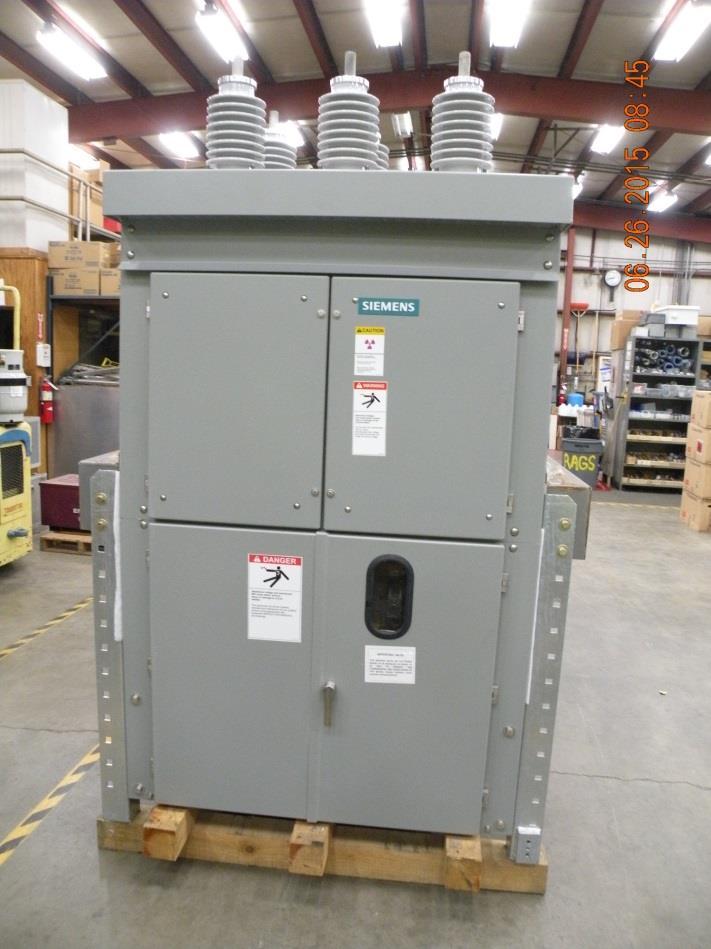
21 Microprocessor ased Feeder reaker

22 Can you automate this please? Older Electromechanical based design PSE has over 1,260 Feeder reaker relay Set 10% Modern Day microprocessor based relay sets 20% First Generation Microprocessor based relay sets 70% Electromechanical relay packages
23 Trip Indication elays + TI HLWS DC 51P 51G 50P 50G - TC SHUNT VAISTO (MAGNETIC ACTUATED MECHANISM)

24 Trip Indication elays


25 Documentation Standardize on minimum requirement for relay to be integrated into DA Scheme Device Type Generation of Device Voltage Sensing What DNP points were available How were these points going to be mapped into the SCADA/EMS system Setting group documentation for planners and operators
26 IED-EMS Maps for DA IED TU/EMS Modern Day SV5T (Overcurrent Pickup) LT15 (Overcurrent Trip) 07 (Latch eset) 52A O/C (Status, OC::CC) 79LO (eclosing Lock Out Status) HLWS (LT06,Status, ON::OFF) SUPV/LOCAL (LT03, Status) UF Trip Alarm (XFM or reaker) XXX_OCPICKUP XXX_FLT_TIP ESET XXX XXX_ECL_LKO XXX_HLWS XXX_LCL_MT XXX_UF_TP_S A C D F G H Signifies point is latched closed, once picked up. Latched points must be reset before they are cleared. Signifies control point in EMS. First Generation PUA (Overcurrent Pickup) 51P* (Phase TOC Trip Alarm) 51N* (Neutral TOC Trip Alarm) 52A O/C (Status, OC::CC) 79LOA (ecloser Lockout Alarm) ST_ALMS_LED (Alarm eset) HLWS (Status, ON::OFF) SUPV/LOCAL (Status) UF Trip Alarm (XFM or reaker) XXX_OCPICKUP XXX_FLT_TIP XXX XXX_ECL_LKO ESET XXX_HT_LN_WK XXX_LCL_MT XXX_UF_TP_S A C D F G H
27 Setting Group Tables for econfiguration NAME IED LOAD LIMIT (A) SETTING GOUP FO ECONFIGUATION KNM-23 ING-13 ING-15 KNM-23 X636 XXX ### ING-13 X1424 XXX ### ING-13 X5408 XXX ### ING-15 X1829 XXX ### ING-15 X420 XXX ### ING-15 X76976 XXX ### ING-13 EM ### ING-15 EM ### KNM-23 EM ### SETTING GOUP 1 ECLOSE WILL TIP FO FAULTS DOWNSTEAM SETTING GOUP 2 ECLOSE WILL SIGNAL AND TAGET ONLY FO FAULTS DOWNSTEAM
28 Load Encroachment on non-directional elements PSE has a protection design standard of ensuring bolted end of line (EOL) faults cover 150% of the phase and ground pickups Maintains standard pickup values for reclosers down the feeder Allows higher load limit of circuit than 51P set point
29 Load Encroachment on a non-directional element Proper Supervision is required Operates purely off Positive Sequence Susceptible to assertion during unbalanced faults Unbalanced faults contain all three sequence components 32Q & 32QF set above highest normal imbalance of the system 50P set higher than load limit, absolutely a fault ZLOAD LOP 50P ZLOAD 32QF 32Q 51PTC

30 Future Topics and Discussions Distributed Generation applications in DA schemes Sectionalizer mode for reclosers Event Analysis DMS system integration Staffing Support

31 Questions?
32 Extra Slides Curve Shaving 10 Portion of Curve emoved TIME (SECONDS) Desired Load Limit = 50P 51PTC = 50P 1 Transformer reaker ΔCTI Margin ecloser 1 CUENT 0.1k (AMPEES) 1k 10k ecloser 2
Smart Grid Smarter Protection: Lessons Learned
 1 Smart Grid Smarter Protection: Lessons Learned Kevin Damron and Randy Spacek Avista Utilities Abstract Avista embarked on a smart grid initiative through grants provided by the Department of Energy (DOE)
Time-current Coordination
 269 5.2.3.1 Time-current Coordination Time that is controlled by current magnitude permits discriminating faults at one location from another. There are three variables available to discriminate faults,
Solutions to Common Distribution Protection Challenges
 Solutions to Common Distribution Protection Challenges Jeremy Blair, Greg Hataway, and Trevor Mattson Schweitzer Engineering Laboratories, Inc. Copyright SEL 2016 Common Distribution Protection Problems
Focused Directional Overcurrent Elements (67P, Q and N) for DER Interconnection Protection
 for DER Interconnection Protection") Engineered Solutions for Power System Protection, Automaton and Control APPLICATION NOTE Focused Directional Overcurrent Elements (67P, Q and N) for DER Interconnection Protection 180622 Abstract This
Engineered Solutions for Power System Protection, Automaton and Control APPLICATION NOTE Focused Directional Overcurrent Elements (67P, Q and N) for DER Interconnection Protection 180622 Abstract This
No. SSIEC-PRC SHINSUNG. Polymer Recloser SIREC SERIES 15kV, 27kV, 38kV 400A, 630A, 800A
 No. SSIEC-PRC-00803-1 SHINSUNG Polymer Recloser SIREC SERIES 15kV, 27kV, 38kV 400A, 630A, 800A Introduction SIREC(Solid Insulated Recloser) is designed for outdoor application with lightweight, longlife,
POWER SYSTEM ANALYSIS TADP 641 SETTING OF OVERCURRENT RELAYS
 POWER SYSTEM ANALYSIS TADP 641 SETTING OF OVERCURRENT RELAYS Juan Manuel Gers, PhD Protection coordination principles Relay coordination is the process of selecting settings that will assure that the relays
Notes 1: Introduction to Distribution Systems
 Notes 1: Introduction to Distribution Systems 1.0 Introduction Power systems are comprised of 3 basic electrical subsystems. Generation subsystem Transmission subsystem Distribution subsystem The subtransmission
Babak Enayati National Grid Thursday, April 17
 2014 IEEE PES Transmission & Distribution Conference & Exposition Impacts of the Distribution System Renewable Energy Resources on the Power System Protection Babak Enayati National Grid Thursday, April
Hands-On-Relay School 2015 Distribution Event Analysis. Randy Spacek Protection Engineer Manager
 Hands-On-Relay School 2015 Distribution Event Analysis Randy Spacek Protection Engineer Manager OVERVIEW Available Tools Fault Type Identification: line and transformer Relay Event Record: Oscillography
S&C Vista Underground Distribution Switchgear Outdoor Distribution
 The offers superior overcurrent coordination. Among the features that provide excellent overcurrent coordination are unique coordinating speed tap and main time-current characteristic curves, which provide
Distance Protection for Distribution Feeders. Presented By: Yordan Kyosev, P.Eng. & Curtis Ruff, P.Eng.
 Distance Protection for Distribution Feeders Presented By: Yordan Kyosev, P.Eng. & Curtis Ruff, P.Eng. Why use distance protection for distribution feeders? Distance protection is mainly used for protecting
Protecting Feeders With Distributed Resource Scott Elling HDR Inc HDR, all rights reserved.
 Protecting Feeders With Distributed Resource Scott Elling HDR Inc. 2015 HDR, all rights reserved. Background Several Hundred Mega Watts of distributed PV Distribution Grid is no longer radial Protection
Your NAMI State Organization
 Your NAMI State Organization State: State Organization: Address: Washington NAMI Washington NAMI Washington 1107 NE 45th St. Suite 230 Seattle, WA 98105 Phone: (206) 783-4288 Email Address: Executive Director:
DISTRIBUTION DEVICE COORDINATION
 DISTRIBUTION DEVICE COORDINATION Kevin Damron & Calvin Howard Avista Utilities Presented March th, 08 At the 5 th Annual Hands-On Relay School Washington State University Pullman, Washington TABLE OF CONTENTS
Protection Challenges for Transmission Lines with Long Taps
 Protection Challenges for Transmission Lines with Long Taps Jenny Patten, Majida Malki, Quanta Technology, Matt Jones, American Transmission Co. Abstract Tapped transmission lines are quite common as they
Impacts of the Renewable Energy Resources on the Power System Protection by: Brent M. Fedele, P.E., National Grid for: 11 th Annual CNY Engineering
 Impacts of the Renewable Energy Resources on the Power System Protection by: Brent M. Fedele, P.E., National Grid for: 11 th Annual CNY Engineering Expo - Nov. 3, 2014 Index Normal Distribution System
Digital Line Protection System
 Digital Line Protection System! Microprocessor Based Protection, Control and Monitoring System! Waveform Sampling! Proven Protection! Economical! Ease of Retrofit 1 DLP-D D Enhancements ASCII SUBSET Three
UPGRADING SUBSTATION RELAYS TO DIGITAL RECLOSERS AND THEIR COORDINATION WITH SECTIONALIZERS
 UPGRADING SUBSTATION RELAYS TO DIGITAL RECLOSERS AND THEIR COORDINATION WITH SECTIONALIZERS 1 B. RAMESH, 2 K. P. VITTAL Student Member, IEEE, EEE Department, National Institute of Technology Karnataka,
Addendum Operation Manual IM30-DREK MICROPROCESSOR OVERCURRENT AND DIRECTIONAL EARTH FAULT PROTECTION RELAY + AUTORECLOSE TYPE IM30-DREK ADDENDUM
 K Pag. 1 of 6 MICROPROCESSOR OVERCURRENT AND DIRECTIONAL EARTH FAULT PROTECTION RELAY + AUTORECLOSE TYPE K ADDENDUM OPERATION MANUAL I> I>> O> O>> MICROELETTRICA MILANO SCIENTIFICA ITALY PROG/ I.R.F. I2>
Reducing the Effects of Short Circuit Faults on Sensitive Loads in Distribution Systems
 Reducing the Effects of Short Circuit Faults on Sensitive Loads in Distribution Systems Alexander Apostolov AREVA T&D Automation I. INTRODUCTION The electric utilities industry is going through significant
Implementation of a High-Speed Distribution Network Reconfiguration Scheme
 Implementation of a High-Speed Distribution Network Reconfiguration Scheme Greg Hataway and Ted Warren Schweitzer ngineering Laboratories, Inc Chris Stephens Coweta-Fayette lectric Membership Cooperative
Protective Relaying for DER
 Protective Relaying for DER Rogerio Scharlach Schweitzer Engineering Laboratories, Inc. Basking Ridge, NJ Overview IEEE 1547 general requirements to be met at point of common coupling (PCC) Distributed
No. SSIEC-SEW SHINSUNG. Solid Insulation Eco Load Break Switch (SILO) SILO SERIES 15kV, 27kV 400A, 630A
 SILO SERIES 15kV, 27kV 400A, 630A") SHINSUNG Solid Insulation Eco Load Break Switch (SILO) SILO SERIES 15kV, 27kV 400A, 630A Enhanced Self Healing System General SILO is 3 phase, solid insulated load break switch (LBS) and vacuum interruption
SHINSUNG Solid Insulation Eco Load Break Switch (SILO) SILO SERIES 15kV, 27kV 400A, 630A Enhanced Self Healing System General SILO is 3 phase, solid insulated load break switch (LBS) and vacuum interruption
Arizona Public Service Company and the Transmission Partnership for National Electric Power Company of Jordan
 Arizona Public Service Company and the Transmission Partnership for National Electric Power Company of Jordan Mark Hackney October 5-8, 2009 Amman, Jordan Energy Control Center Layout 2 Energy Control
Overcurrent Elements
 Exercise Objectives Hands-On Relay Testing Session Overcurrent Elements After completing this exercise, you should be able to do the following: Identify overcurrent element settings. Determine effective
U I. Time Overcurrent Relays. Basic equation. More or less approximates thermal fuse. » Allow coordination with fuses 9/24/2018 ECE525.
 Time Overcurrent Relays More or less approximates thermal fuse» Allow coordination with fuses Direction of Current nduced Torque Restraining Spring Reset Position Time Dial Setting Disk Basic equation
System Protection and Control Seminar
 System Protection and Control Seminar Desirable Protection We want to detect a fault within 100% of the zone of protection. We want to avoid interrupting non-faulted zones of protection. We want to clear
NERC Protection Coordination Webinar Series June 9, Phil Tatro Jon Gardell
 Power Plant and Transmission System Protection Coordination GSU Phase Overcurrent (51T), GSU Ground Overcurrent (51TG), and Breaker Failure (50BF) Protection NERC Protection Coordination Webinar Series
NERC Protection Coordination Webinar Series June 16, Phil Tatro Jon Gardell
 Power Plant and Transmission System Protection Coordination Phase Distance (21) and Voltage-Controlled or Voltage-Restrained Overcurrent Protection (51V) NERC Protection Coordination Webinar Series June
Distribution Feeder. Nazar Dhahir Sr. Transmission Engineer Tucson Electric Power Co. RMEL Distribution Conference March 11, 2010
 Distribution Feeder utomation ti Nazar Dhahir Sr. Transmission Engineer Tucson Electric Power Co. RMEL Distribution Conference March 11, 2010 IntelliTEM Team synchronization members share data Switches
Transmission Line Applications of Directional Ground Overcurrent Relays. Working Group D24 Report to the Line Protection Subcommittee January 2014
 Transmission Line Applications of Directional Ground Overcurrent Relays Working Group D24 Report to the Line Protection Subcommittee January 2014 Working Group Members: Don Lukach (Chairman), Rick Taylor
SEATTLE CITY LIGHT DISTRIBUTION AUTOMATION
 SEATTLE CITY LIGHT DISTRIBUTION AUTOMATION Ryan Pham Project manager 0/27/206 AGENDA. Distribution automation background 2. Seattle City Light pilot project 3. System performance windstorm 08/29/5 4. Lessons
Detecting and Managing Geomagnetically Induced Currents With Relays
 Detecting and Managing Geomagnetically Induced Currents With Relays Copyright SEL 2013 Transformer Relay Connections Voltage Current Control RTDs Transformer Protective Relay Measures differential current
EE Lecture 14 Wed Feb 8, 2017
 EE 5223 - Lecture 14 Wed Feb 8, 2017 Ongoing List of Topics: URL: http://www.ece.mtu.edu/faculty/bamork/ee5223/index.htm Labs - EE5224 Lab 3 - begins on Tues Feb 14th Term Project - details posted. Limit
PLAN... RESPOND... RESTORE! Utility Automation & Information Technology... Automation Rising
 Automation Rising Q U A R T E R LY First Quarter 2013 The Digital Magazine of Automation & Information Technology for Electric, Gas and Water Utilities Utility Automation & Information Technology... PLAN...
A Tutorial on the Application and Setting of Collector Feeder Overcurrent Relays at Wind Electric Plants
 A Tutorial on the Application and Setting of Collector Feeder Overcurrent Relays at Wind Electric Plants Martin Best and Stephanie Mercer, UC Synergetic, LLC Abstract Wind generating plants employ several
Numbering System for Protective Devices, Control and Indication Devices for Power Systems
 Appendix C Numbering System for Protective Devices, Control and Indication Devices for Power Systems C.1 APPLICATION OF PROTECTIVE RELAYS, CONTROL AND ALARM DEVICES FOR POWER SYSTEM CIRCUITS The requirements
Cross-Connection Control Specialists Public List
 Cross-Connection Control Specialists Public List July 12, 2006 Welcome to the Public List of Cross-Connection Control Specialists (CCS) for Washington State. CCSs on the Public List are available to help
EE 741 Spring Electric Power Distribution Systems An Overview
 EE 741 Spring 2017 Electric Power Distribution Systems An Overview Basic Power System Layout There are over 100 substations in the Las Vegas Valley pic of closest substation Substation Design Substation
Phone: Address: 720 6th Street, Suite B, Clarkston, WA Web site:
 Adams Conservation District Phone: 509-659-1553 118 E. Main, Ritzville, WA 99169 chadamscd@hotmail.com http://www.adamscd.com/ Asotin County Conservation District Phone: 509-552-8117 720 6th Street, Suite
SECTION SHORT CIRCUIT, COMPONENT PROTECTION, FLASH HAZARD AND SELECTIVE COORDINATION STUDY
 SECTION 16075 - SHORT CIRCUIT, COMPONENT PROTECTION, FLASH HAZARD AND SELECTIVE COORDINATION STUDY PART 1 GENERAL 1.1 SUMMARY A. Section Includes: 1. Provide a short-circuit, component protection, flash
Solutions to Common Distribution Protection Challenges
 1 Solutions to Common Distribution Protection Challenges Jeremy Blair, Greg Hataway, and Trevor Mattson, Schweitzer Engineering Laboratories, Inc. 235 NE Hopkins Court, Pullman, WA 99163 USA, +1.59.332.189
Transmission Protection Overview
 Transmission Protection Overview 2017 Hands-On Relay School Daniel Henriod Schweitzer Engineering Laboratories Pullman, WA Transmission Line Protection Objective General knowledge and familiarity with
Issued: September 2, 2014 Effective: October 3, 2014 WN U-60 Attachment C to Schedule 152, Page 1 PUGET SOUND ENERGY
 WN U-60 Attachment C to Schedule 152, Page 1 SCHEDULE 152 APPLICATION FOR INTERCONNECTING A GENERATING FACILITY TIER 2 OR TIER 3 This Application is considered complete when it provides all applicable
Transmission Line Protection Objective. General knowledge and familiarity with transmission protection schemes
 Transmission Line Protection Objective General knowledge and familiarity with transmission protection schemes Transmission Line Protection Topics Primary/backup protection Coordination Communication-based
Transformer Protection
 Transformer Protection Transformer Protection Outline Fuses Protection Example Overcurrent Protection Differential Relaying Current Matching Phase Shift Compensation Tap Changing Under Load Magnetizing
BUS2000 Busbar Differential Protection System
 BUS2000 Busbar Differential Protection System Differential overcurrent system with percentage restraint protection 1 Typical Busbar Arrangements Single Busbar Double Busbar with Coupler Breaker and a Half
MGFR. the power to protect MGFR. www. ElectricalPartManuals. com. Instruction Manual C-322
 MGF MGF GOUND Fault ELAY the power to protect Instruction Manual C-322 Ground fault relay GLOSSAY A/D DMT EMF IDMT P.U. MS TCP UPS ZSIP ZSCT Analog to Digital Definite Minimum Time Electro Motive Force
Application Note Assigning and Reducing the DNP V3.0 Points List on the ABB PCD Timothy S. Fahey, PE
 Application Note Assigning and Reducing the DNP V3.0 s List on the ABB PCD Timothy S. Fahey, PE Introduction This document defines a subset of the full points list given in the DNP 3.0 Implementation Details
Christopher Substation
 Lessons Learned Relay work is hard and stressful, somedays you are the hero.other days you are the goat. Here are some true stories from the field that demonstrate some hero, but mostly goat. Lessons Learned
Texas Reliability Entity Event Analysis. Event: May 8, 2011 Loss of Multiple Elements Category 1a Event
 Texas Reliability Entity Event Analysis Event: May 8, 2011 Loss of Multiple Elements Category 1a Event Texas Reliability Entity July 2011 Page 1 of 10 Table of Contents Executive Summary... 3 I. Event
Directional STANDARDS: Overcurrent Relaying
 A CABLE Technicians TESTING Approach to Directional STANDARDS: Overcurrent Relaying Understanding O V E R V I E W and O F Testing T H E Directional Relays 1 Moderator n Ron Spataro AVO Training Institute
Relay Coordination in the Protection of Radially- Connected Power System Network
 Relay Coordination in the Protection of Radially- Connected Power System Network Zankhana Shah Electrical Department, Kalol institute of research centre, Ahemedabad-Mehshana Highway, kalol, India 1 zankhu.shah@gmail.com
PROTECTION SIGNALLING
 PROTECTION SIGNALLING 1 Directional Comparison Distance Protection Schemes The importance of transmission system integrity necessitates high-speed fault clearing times and highspeed auto reclosing to avoid
Phase and neutral overcurrent protection
 Phase and neutral overcurrent protection Page 1 ssued June 1999 Changed since July 1998 Data subject to change without notice (SE970165) Features Two-phase or three-phase time-overcurrent and earth fault
7PG21 Solkor R/Rf Pilot Wire Current Differential Protection Answers for energy
 Reyrolle Protection Devices 7PG21 Solkor R/Rf Pilot Wire Current Differential Protection Answers for energy 7PG21 Solkor R/Rf Pilot Wire Current Differential Protection Description Additional Options Solkor
Distance Protection in Distribution Systems: How It Assists With Integrating Distributed Resources
 1 Distance Protection in Distribution Systems: How It Assists With Integrating Distributed Resources David Martin and Pankaj Sharma, Hydro One Networks Inc. Amy Sinclair and Dale Finney, Schweitzer Engineering
Electrical Protection System Design and Operation
 ELEC9713 Industrial and Commercial Power Systems Electrical Protection System Design and Operation 1. Function of Electrical Protection Systems The three primary aims of overcurrent electrical protection
Using a Multiple Analog Input Distance Relay as a DFR
 Using a Multiple Analog Input Distance Relay as a DFR Dennis Denison Senior Transmission Specialist Entergy Rich Hunt, M.S., P.E. Senior Field Application Engineer NxtPhase T&D Corporation Presented at
Protection Basics Presented by John S. Levine, P.E. Levine Lectronics and Lectric, Inc GE Consumer & Industrial Multilin
 Protection Basics Presented by John S. Levine, P.E. Levine Lectronics and Lectric, Inc. 770 565-1556 John@L-3.com 1 Protection Fundamentals By John Levine 2 Introductions Tools Outline Enervista Launchpad
ARC FLASH PPE GUIDELINES FOR INDUSTRIAL POWER SYSTEMS
 The Electrical Power Engineers Qual-Tech Engineers, Inc. 201 Johnson Road Building #1 Suite 203 Houston, PA 15342-1300 Phone 724-873-9275 Fax 724-873-8910 www.qualtecheng.com ARC FLASH PPE GUIDELINES FOR
200ADM-P. Current Injection System with Phase Shift A 3.000s 2.000A 50.00Hz 0.0. Features
 CT ratio Power Harmonics ac+dc 200ADM-P Current Injection System with Phase Shift Features 0-200A output current True RMS metering with 1 cycle capture Variable auxiliary AC voltage/current output with
Transmission System Phase Backup Protection
 Reliability Guideline Transmission System Phase Backup Protection NERC System Protection and Control Subcommittee Draft for Planning Committee Approval June 2011 Table of Contents 1. Introduction and Need
EE Lecture 15 (recorded Feb 9, 2011) Fri Feb 15, 2013
 Fri Feb 15, 2013") EE 5223 - Lecture 15 (recorded Feb 9, 2011) Fri Feb 15, 2013 Ongoing List of Topics: URL: http://www.ece.mtu.edu/faculty/bamork/ee5223/index.htm Term Project - structuring, details Exercises posted Today:
EE 5223 - Lecture 15 (recorded Feb 9, 2011) Fri Feb 15, 2013 Ongoing List of Topics: URL: http://www.ece.mtu.edu/faculty/bamork/ee5223/index.htm Term Project - structuring, details Exercises posted Today:
BED INTERCONNECTION TECHNICAL REQUIREMENTS
 BED INTERCONNECTION TECHNICAL REQUIREMENTS By Enis Šehović, P.E. 2/11/2016 Revised 5/19/2016 A. TABLE OF CONTENTS B. Interconnection Processes... 2 1. Vermont Public Service Board (PSB) Rule 5.500... 2
Reyrolle Protection Devices. 7PG21 Solkor R/Rf Pilot Wire Current Differential Protection. Answers for energy
 Reyrolle Protection Devices 7PG21 Solkor R/Rf Pilot Wire Current Differential Protection Answers for energy 7PG21 Solkor R/Rf Pilot Wire Current Differential Protection Additional Options 15kV Isolation
Protection & Control Journal
 Protection & Control Journal March 2007 Innovative Distribution Feeder Protection Improving data throughput on a wireless IED network Secure Substation Automation Addressing Window Type Transformer Proximity
www. ElectricalPartManuals. com Type CGR Ratio Ground Relay Descriptive Bulletin Page 1
 November, 1981 New nformation Mailed to: E,D,C/211, 219/DB Westinghouse Electric Corporation Relay-nstrument Division Coral Springs, FL 65 Page 1 Type CGR Ratio Ground Relay "" Page 2 Application Three
7PG21 Solkor R/Rf Pilot Wire Current Differential Protection Energy Management
 Reyrolle Protection Devices 7PG21 Solkor R/Rf Pilot Wire Current Differential Protection Energy Management 7PG21 Solkor R/Rf Pilot Wire Current Differential Protection Description Solkor R & Solkor Rf
Adaptive Relaying of Radial Distribution system with Distributed Generation
 Adaptive Relaying of Radial Distribution system with Distributed Generation K.Vijetha M,Tech (Power Systems Engineering) National Institute of Technology-Warangal Warangal, INDIA. Email: vijetha258@gmail.com
Error Correction and Hidden Failure Detection in Centralized Substation Protection
 Error Correction and Hidden Failure Detection in Centralized Substation Protection Sakis Meliopoulos*, George Cokkinides*, Paul Myrda** and E. Farantatos** * Georgia Institute of Technology, Atlanta, Georgia
Power System Fundamentals
 Power System Fundamentals Relay Applications PJM State & Member Training Dept. Objectives At the end of this presentation the Student will be able to: Describe the purpose of protective relays Identify
Lessons Learned. Paul Luther. Puget Sound Energy
 Lessons Learned Paul Luther Puget Sound Energy Lessons Learned Relay work is hard and stressful, somedays you are the hero.other days you are the goat. Here are some true stories from the field that demonstrate
DG TRANSFER CONNECTION SCHEME IN ACTIVE DISTRIBUTION NETWORKS
 DG TRANSFER CONNECTION SCHEME IN ACTIVE DISTRIBUTION NETWORKS Abdelrahman AKILA Ahmed HELAL Hussien ELDESOUKI SDEDCO Egypt AASTMT Egypt AASTMT Egypt Abdurrahman.akela@gmail.com ahmedanas@aast.edu hdesouki@aast.edu
Protection & Control Challenges with Distributed Generation
 2015 Hydro One. All rights reserved. Operating Effectiveness Hydro One Networks Inc Protection & Control Challenges with Distributed Generation Pankaj Sharma, P Eng. Grid Operations Manager Operating Effectiveness
1 INTRODUCTION 1.1 PRODUCT DESCRIPTION
 GEK-00682D INTRODUCTION INTRODUCTION. PRODUCT DESCRIPTION The MDP Digital Time Overcurrent Relay is a digital, microprocessor based, nondirectional overcurrent relay that protects against phase-to-phase
Increased Reliability of EHV Systems through Station Switchable Spare Transformer and Shunt Reactor Design and Operation
 21, rue d Artois, F-75008 PARIS CIGRE US National Committee http : //www.cigre.org 2015 Grid of the Future Symposium Increased Reliability of EHV Systems through Station Switchable Spare Transformer and
Power systems Protection course
 Al-Balqa Applied University Power systems Protection course Department of Electrical Energy Engineering 1 Part 5 Relays 2 3 Relay Is a device which receive a signal from the power system thought CT and
Washington Association of County Commissioner/Council Clerks
 (3/29/18) Washington Association of County Commissioner/Council Clerks Patricia Phillips Adams County 210 W Broadway Ritzville WA 99169 Phone: (509) 659-3236 Email: patriciap@co.adams.wa.us Vivian Bly
Supplemental Motor Protection Devices Specifications
 Technical Data Supplemental Motor Protection Devices Specifications Bulletin Numbers 809S, 813S, 814S, 817S, 1409, 1410 Topic Page 809S/813S/814S/817 Dedicated Function Motor Protection Relays 2 Product
PJM Manual 07:: PJM Protection Standards Revision: 2 Effective Date: July 1, 2016
 PJM Manual 07:: PJM Protection Standards Revision: 2 Effective Date: July 1, 2016 Prepared by System Planning Division Transmission Planning Department PJM 2016 Table of Contents Table of Contents Approval...6
O V E R V I E W O F T H E
 A CABLE Technicians TESTING Approach to Generator STANDARDS: Protection O V E R V I E W O F T H E 1 Moderator n Ron Spataro AVO Training Institute Marketing Manager 2 Q&A n Send us your questions and comments
Implementing Distribution Automation and Protection
 Implementing Distribution Automation and Protection Karl Zimmerman and ike Collum Schweitzer Engineering Laboratories, Inc. Published in the SEL Journal of Reliable Power, olume 1, Number 2, October 2010
Fuseless Capacitor Bank Protection
 Fuseless Bank Protection Minnesota Power Systems Conference St. Paul, MN. November 2, 1999 by: Tom Ernst, Minnesota Power Other Papers of Interest Presented at Western Protective Relay Conference, Oct.
Design and Simulation of superconducting fault current limiter
 Research Inventy: International Journal of Engineering And Science Vol.5, Issue 3 (March 2015), PP -06-13 Issn (e): 2278-4721, Issn (p):2319-6483, www.researchinventy.com Design and Simulation of superconducting
TECHNICAL SPECIFICATIONS AND OPERATING PROTOCOLS AND PROCEDURES FOR INTERCONNECTION OF GENERATION FACILITIES NOT SUBJECT TO FERC JURISDICTION
 TECHNICAL SPECIFICATIONS AND OPERATING PROTOCOLS AND PROCEDURES FOR INTERCONNECTION OF GENERATION FACILITIES NOT SUBJECT TO FERC JURISDICTION Document 9022 Puget Sound Energy, Inc. PSE-TC-160.70 December
This section applies to the requirements for the performance of power system studies by both the Design Engineer and the Contractor.
 Basis of Design This section applies to the requirements for the performance of power system studies by both the Design Engineer and the Contractor. Background Information A Short Circuit and Coordination
MiCOM P120, P121, P122 and P123 Universal Overcurrent Relays
 MiOM P120, P121, P122 and P123 : Universal Overcurrent Relays MiOM P120, P121, P122 and P123 Universal Overcurrent Relays T & D Energy utomation & Information MiOM P120, P121, P122 and P123 whole range
Power Plant and Transmission System Protection Coordination
 Agenda Item 5.h Attachment 1 A Technical Reference Document Power Plant and Transmission System Protection Coordination Draft 6.9 November 19, 2009 NERC System Protection and Control Subcommittee November
This webinar brought to you by the Relion product family Advanced protection and control IEDs from ABB
 This webinar brought to you by the Relion product family Advanced protection and control IEDs from ABB Relion. Thinking beyond the box. Designed to seamlessly consolidate functions, Relion relays are smarter,
Supplemental Motor Protection Devices Specifications
 Technical Data Supplemental Motor Protection Devices Specifications Bulletin Numbers 809S, 813S, 814S, 817S, 1409, 1410 Topic Bulletin 809S/813S/814S/817S 2 Page Product Line Overview 2 Cat. No. Explanation
One line and Three line diagrams Schematics Wiring Diagrams Logic ladders Ancillary prints Pictorial instructions
 One line and Three line diagrams Schematics Wiring Diagrams Logic ladders Ancillary prints Pictorial instructions One line diagram (1) One line diagrams will typically show in a simple fashion an over
THE ROLE OF SYNCHROPHASORS IN THE INTEGRATION OF DISTRIBUTED ENERGY RESOURCES
 THE OLE OF SYNCHOPHASOS IN THE INTEGATION OF DISTIBUTED ENEGY ESOUCES Alexander APOSTOLOV OMICON electronics - USA alex.apostolov@omicronusa.com ABSTACT The introduction of M and P class Synchrophasors
TECHNICAL BULLETIN 004a Ferroresonance
 May 29, 2002 TECHNICAL BULLETIN 004a Ferroresonance Abstract - This paper describes the phenomenon of ferroresonance, the conditions under which it may appear in electric power systems, and some techniques
ekor.rpa Protection, metering and control multifunction unit General Instructions IG-267-EN, version 01, 07/04/2017 LIB
 Protection, metering and control multifunction unit General Instructions IG-267-EN, version 01, 07/04/2017 LIB CAUTION! When medium-voltage equipment is operating, certain components are live, other parts
Case Study of a Multiterminal Generation Interconnect Scheme
 Case Study of a Multiterminal Generation Interconnect Scheme Joel Lopez and Juan Martinez Imperial Irrigation District Sam Fulford and Kamal Garg Schweitzer Engineering Laboratories, Inc. Presented at
High Impedance Fault Detection and Backup Protection A Case Study
 High Impedance Fault Detection and Backup Protection A Case Study Ian T. Riensche, P.E., Relay Application Innovation, Inc. John P. Merrell, P.E., Tacoma Power Keywords: high impedance faults, open conductor,
Transformer protection IED RET 670
 Gunnar Stranne Transformer protection IED RET 670 Santiago Septiembre 5, 2006 1 Transformer protection IED RET670 2 Introduction features and applications Differential protection functions Restricted Earth
OVERCURRENT PROTECTION RELAY GRD110
 INSTRUCTION MANUAL OVERCURRENT PROTECTION RELAY GRD110 TOSHIBA Corporation 2002 All Rights Reserved. ( Ver. 3.1) Safety Precautions Before using this product, please read this chapter carefully. 1 This
MAINTENANCE MANUAL 1B170K17 FOUR SHOT AUTO RECLOSE RELAY
 Sheet 1 of 9 MAINTENANCE MANUAL 1B170K17 FOUR SHOT AUTO RECLOSE RELAY The Maintenance Manual is to be read in conunction with Product/Test Manual Sheet 2 of 9 INDEX 1. FULL DESCRIPTION OF OPERATION 1.1