MAINTENANCE MANUAL MHz NOISE BLANKER 19A704991P105
|
|
|
- Leo Washington
- 5 years ago
- Views:
Transcription
1 MAINTENANCE MANUAL MHz NOISE BLANKER 19A704991P105 TABLE OF CONTENTS Page DESCRIPTION... 1 INSTALLATION... 1 CIRCUIT ANALYSIS... 1 OUTLINE DIAGRAM... 4 SCHEMATIC DIAGRAM... 5 PARTS LIST... 5 DESCRIPTION The Noise Blanker option for the MLS synthesized radio consists of a plug-in printed wire board which plugs into J503 on the receiver board. The noise blanker is designed to improve receiver performance by blanking out impulse noise emanating from the alternator, ignition system, etc. This is accomplished by delaying the IF signal for 200 nanoseconds while generating a blanking pulse having the same characteristics as the noise pulses. These blanking pulses then are used to turn off the delayed IF signal precisely where the noise occurs, resulting in noise-free audio reception. The noise blanker may be disabled, if desired, by relocating ground plug P505 on the receiver board. An alternate method (if the noise blanker is to be permanently disabled) is to remove the noise blanker board from the radio and reconnect W501. INSTALLATION The noise blanker plugs into J503 on the receiver. If the board is installed after the receiver has been aligned (or installed in the field), cut jumper wire W501 on the receiver board. Be sure that P505 is plugged into J505-2 & 3. Set the output signal level of the RF signal generator so as to obtain 12 db SlNAD at audio output and adjust L503 on the receiver board to obtain maximum SlNAD sensitivity reading. NOTE If the noise blanker is installed prior to receiver alignment, simply plug the noise blanker into J503 and perform standard receiver alignment procedures. Be sure that P505 is plugged into J505-2 and 3 on the receiver board. Refer to the Receiver Alignment Procedures. Be sure P505 is plugged into J505-2 & 3 on the receiver board. Refer to the Receiver Alignment Procedure in the Service Section of the Maintenance Manual and tune accordingly. CIRCUIT ANALYSIS The noise blanker consists of: a 200 nanosecond fixed delay line, a 20.8 MHz rejection filter, three pulse amplifiers, a pulse amplifier/limiter, a gate driver, a blanker disable switch, a pulse detector, and FET blanking switches. A block diagram is provided in Figure 1. The IF signal from JFET buffer TR501 on the receiver board is applied to gate 1 of pulse amplifier TR1 through 20.8 MHz rejection filter FL1. The signal is also applied to delay line Z1. Z1 delays the IF signal by 200
2 nanoseconds and returns it to the two JFET gating switches TR7 and TR8. The IF signal is amplified by pulse amplifier TR1 that provides a gain of approximately 20dB. Bias for TR1 is established by R1 and R2. The output of TR1 is further amplified and limited by pulse amplifier/limiter IC1. IC1 provides a gain of approximately 50 db. The threshold bias for TR2 is established by R8-R11, and CD1. R9 is a negative temperature compensating resistor whose temperature characteristics complement ICI to adjust the threshold level of TR2 with changes in temperature. The detected pulse is taken from the collector of TR2 and further amplified by pulse amplifiers TR3 and TR5. C14 in the emitter circuit of TR3 provides a low frequency bypass to ground and also maintains a full charge to allow TR3 to be switched on and off more rapidly. The output of pulse amplifier TR5 is applied to gate driver TR6. TR6 provides drive to operate the two JFET switches (TR7 & TR8). The delayed IF signal from delay line Z1 arrives at TR7 and TR8 at the same time as the gating pulses from the blanker switch. The gating pulse switches TR7 and TR8 on coincident with the noise pulses on the IF signal, shunting all noise pulses to ground. BLANKER DISABLE Blanker disable input is provided to assure complete turn off of the noise blanker function while allowing the delayed IF signal to be processed through the receiver. BLKR DIS 1 (TP3) is applied to pulse amplifier TR1 gate 2. This will nearly turn off TR1. BLKR DIS 2 (TP4) is applied to the base of TR4, turning it on. TR4 shorts the emitter and collector of pulse amplifier TR3, preventing any remaining noise pulses from passing. MODIFICATION INSTRUCTIONS These instructions provide a detailed description of the necessary modifications required when installing the noise blanker in the MLS Low Band radio. Parts Required The following parts are all supplied in kit B19/CFR-80. Noise Blanker Unit... MPXP02021 Threaded Spacer... MTK Split lockwasher... BSSW03000S Mounting screw (quantity 2)... BSNA03008S Manual Request Card... ECR3224 Procedure 1. Remove the bottom cover from the radio. 2. Remove or cut wire link W501 on the receiver board of the MLS radio. W501 is identified in Figure Mount the threaded spacer and the split lockwasher in location A (See Figures 2 & 3). 4. Plug in the noise blanker unit at J503 on the receiver board in the radio. 5. Secure the noise blanker unit using the two mounting screws. Figure 1 Block Diagram Copyright , Com-Net Ericsson Critical Radio Systems, Inc. All rights reserved. 2
3 Figure 2 Partial Bottom View of MLS Low Band Radio Figure 3 Installation of Noise Blanker 3

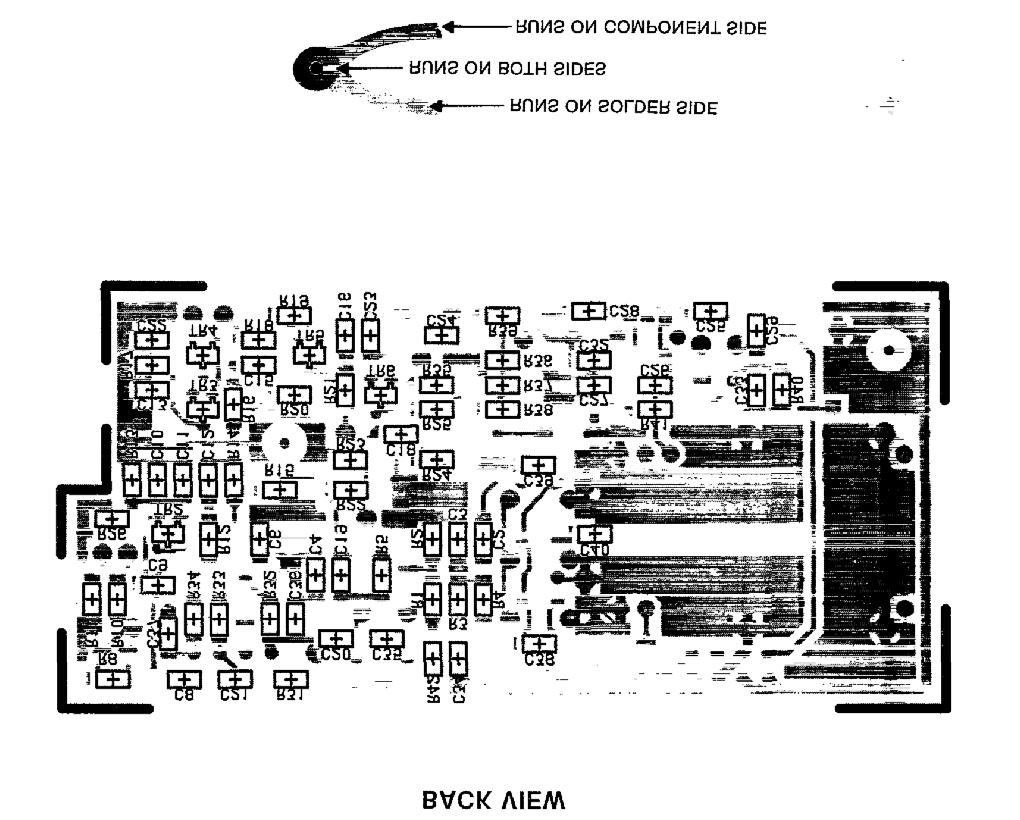
4 OUTLINE DIAGRAM 4
5 SCHEMATIC DIAGRAM LBI-38117A 5
6 PARTS LIST 6
7 This page intentionally left blank 7
8 Com-Net Ericsson Critical Radio Systems, Inc. P.O. Box 2000 Lynchburg, Virginia or (Outside USA, ) Printed in U.S.A.
Maintenance Manual TRANSMITTER/RECEIVER BOARD CMN-233 FOR MLSH041
 Maintenance Manual TRANSMITTER/RECEIVER BOARD CMN-233 FOR MLSH041 TABLE OF CONTENTS Page DESCRIPTION... 2 CIRCUIT ANALYSIS... 2 Transmitter... 2 9-volt Regulator... 2 Exciter... 2 40-Watt PA... 2 Antenna
MAINTENANCE MANUAL TRANSMITTER/RECEIVER BOARD CMN-234A/B FOR MLSU141 & MLSU241 UHF MOBILE RADIO TABLE OF CONTENTS
 MAINTENANCE MANUAL TRANSMITTER/RECEIVER BOARD CMN-234A/B FOR MLSU141 & MLSU241 UHF MOBILE RADIO TABLE OF CONTENTS DESCRIPTION... 2 CIRCUIT ANALYSIS... 2 TRANSMITTER... 2 9-Voft Regulator... 2 Exciter...
ERICSSONZ LBI-30398P. MAINTENANCE MANUAL MHz PHASE LOCKED LOOP EXCITER 19D423249G1 & G2 DESCRIPTION TABLE OF CONTENTS
 MAINTENANCE MANUAL 138-174 MHz PHASE LOCKED LOOP EXCITER 19D423249G1 & G2 TABLE OF CONTENTS Page DESCRIPTION... Front Cover CIRCUIT ANALYSIS...1 MODIFICATION INSTRUCTIONS...4 PARTS LIST...5 PRODUCTION
LBI-30705L INSTRUCTIONS FOR AUDIO BOARDS 19A129924G1-G3 DESCRIPTION CIRCUIT ANALYSIS ERICSSONZM ERICSSONZM TABLE OF CONTENTS. Audio Board 19A129924G1
 ERICSSONZM INSTRUCTIONS FOR AUDIO BOARDS 19A129924G1-G3 L TABLE OF CONTENTS Page DESCRIPTION............................................... Front Cover CIRCUIT ANALYSIS............................................
ericssonz LBI-38640E MAINTENANCE MANUAL FOR VHF TRANSMITTER SYNTHESIZER MODULE 19D902780G1 DESCRIPTION
 MAINTENANCE MANUAL FOR VHF TRANSMITTER SYNTHESIZER MODULE 19D902780G1 TABLE OF CONTENTS Page DESCRIPTION........................................... Front Cover GENERAL SPECIFICATIONS...................................
LBI-38673F MAINTENANCE MANUAL FOR RECEIVER FRONT END MODULE 19D902782G3, G4, & G7 DESCRIPTION TABLE OF CONTENTS
 MAINTENANCE MANUAL FOR 19D902782G3, G4, & G7 TABLE OF CONTENTS Page DESCRIPTION........................................... Front Cover SPECIFICATIONS......................................... 1 CIRCUIT
LBI-30398N. MAINTENANCE MANUAL MHz PHASE LOCK LOOP EXCITER 19D423249G1 & G2 DESCRIPTION TABLE OF CONTENTS. Page. DESCRIPTION...
 MAINTENANCE MANUAL 138-174 MHz PHASE LOCK LOOP EXCITER 19D423249G1 & G2 LBI-30398N TABLE OF CONTENTS DESCRIPTION...Front Cover CIRCUIT ANALYSIS... 1 MODIFICATION INSTRUCTIONS... 4 PARTS LIST AND PRODUCTION
ERICSSONZ LBI-38638C MAINTENANCE MANUAL FOR POWER MODULE 19D902589G1 DESCRIPTION CIRCUIT ANALYSIS TABLE OF CONTENTS FILTERED A+
 LBI-38638C MAINTENANCE MANUAL FOR 19D902589G1 TABLE OF CONTENTS Page DESCRIPTION........................................... Front.. Cover CIRCUIT ANALYSIS........................................ Front..
1.0 General Description
 1.0 General Description Figure 1 - Plug-N-Play Noise Blanker for the Collins 75S-1 Series The Collins Noise Blanker is designed to be a Plug-N-Play accessory for the Collins 75S-1 series. The Noise Blanker
Maintenance Manual ERICSSONZ LBI-31552E
 E Maintenance Manual TONE REMOTE CONTROL BOARD 19A704686P4 (1-Frequency Transmit Receive with Channel Guard) 19A704686P6 (4-Frequency Transmit Receive with Channel Guard) ERICSSONZ Ericsson Inc. Private
MAINTENANCE MANUAL. MDX POWER AMPLIFIER BOARDS 19D904792G2 ( MHz) 19D904792G1 ( MHz) 19D904792G3 ( MHz) TABLE OF CONTENTS
 19D904792G1 ( MHz) 19D904792G3 ( MHz) TABLE OF CONTENTS") LBI-39051C MAINTENANCE MANUAL MDX POWER AMPLIFIER BOARDS 19D904792G2 (403-440 MHz) 19D904792G1 (440-470 MHz) 19D904792G3 (470-512 MHz) TABLE OF CONTENTS Page DESCRIPTION... 1 CIRCUIT ANALYSIS... 1 SERVICE
LBI-39051C MAINTENANCE MANUAL MDX POWER AMPLIFIER BOARDS 19D904792G2 (403-440 MHz) 19D904792G1 (440-470 MHz) 19D904792G3 (470-512 MHz) TABLE OF CONTENTS Page DESCRIPTION... 1 CIRCUIT ANALYSIS... 1 SERVICE
PA FAN PLATE ASSEMBLY 188D6127G1 SYMBOL PART NO. DESCRIPTION. 4 SBS /10 Spring nut. 5 19A702339P510 Screw, thread forming, flat head.
 MAINTENANCE MANUAL 851-870 MHz, 110 WATT POWER AMPLIFIER 19D902797G5 TABLE OF CONTENTS Page DESCRIPTION.............................................. Front Page SPECIFICATIONS.................................................
MAINTENANCE MANUAL MHz OSCILLATOR/MULTIPLIER BOARD 19D423078G1-G8
 MAINTENANCE MANUAL 25-50 MHz OSCILLATOR/MULTIPLIER BOARD 19D423078G1-G8 G (DF1106) (DF1119 IMTS) TABLE OF CONTENTS Page DESCRIPTION.............................................. Front Cover CIRCUIT ANALYSIS...........................................
ericssonz LBI-38642C MAINTENANCE MANUAL RECEIVER FRONT END MODULE 19D902782G1: MHz 19D902782G2: MHz DESCRIPTION TABLE OF CONTENTS
 LBI-38642C MAINTENANCE MANUAL RECEIVER FRONT END MODULE 19D902782G1: 136-151 MHz 19D902782G2: 150-174 MHz TABLE OF CONTENTS Page DESCRIPTION............................................... Front Cover SPECIFICATIONS.............................................
ERICSSONZ LBI-39129B MAINTENANCE MANUAL FOR RECEIVER FRONT END MODULE 19D902782G6, G8, G9, G10, G11, G12 DESCRIPTION TABLE OF CONTENTS
 MAINTENANCE MANUAL FOR 19D902782G6, G8, G9, G10, G11, G12 TABLE OF CONTENTS Page DESCRIPTION........................................... Front. Cover SPECIFICATIONS..........................................
MAINTENANCE MANUAL AUDIO AMPLIFIER BOARD 19D904025G1 (MDR) AUDIO AMPLIFIER BOARD 19D904025G2 (MDX)
 AUDIO AMPLIFIER BOARD 19D904025G2 (MDX)") A MAINTENANCE MANUAL AUDIO AMPLIFIER BOARD 19D904025G1 (MDR) AUDIO AMPLIFIER BOARD 19D904025G2 (MDX) TABLE OF CONTENTS DESCRIPTION............................................... Page Front Cover CIRCUIT
A MAINTENANCE MANUAL AUDIO AMPLIFIER BOARD 19D904025G1 (MDR) AUDIO AMPLIFIER BOARD 19D904025G2 (MDX) TABLE OF CONTENTS DESCRIPTION............................................... Page Front Cover CIRCUIT
MASTR II AUXILIARY RECEIVER 19D417546G7 & G8 & ANTENNA MATCHING UNITS 19C321150G1-G2. Maintenance Manual LBI-30766L. Mobile Communications
 L Mobile Communications MASTR II AUXILIARY RECEIVER 19D417546G7 & G8 & ANTENNA MATCHING UNITS 19C321150G1-G2 Printed in U.S.A Maintenance Manual TABLE OF CONTENTS Page SPECIFICATIONS.....................................................
ADDENDUM NUMBER 2 TO MAINTENANCE MANUAL LBI-38673J Refer to ECO#
 ADDENDUM NUMBER 2 TO MAINTENANCE MANUAL Refer to ECO#20043005 GENERAL This addendum documents a change to the RX Front End Module (19D902782G3, G4, & G7) Maintenance Manual. Torque specification changed
ADDENDUM NUMBER 2 TO MAINTENANCE MANUAL LBI-38642D Refer to ECO# RECEIVER FRONT END PWB 19D902490G1 (19D902490, Sh. 1, Rev.
 ADDENDUM NUMBER 2 TO MAINTENANCE MANUAL Refer to ECO#20026373 RECEIVER FRONT END PWB 19D902490G1 (19D902490, Sh. 1, Rev. 9) 1 ADDENDUM NUMBER 2 TO MAINTENANCE MANUAL Refer to ECO#20026373 RECEIVER FRONT
LBI-39061A. Installation Manual. DTMF Encoder 344A4209P23 (MHDE5U) ericssonz
 ericssonz") LBI-39061A Installation Manual DTMF Encoder 344A4209P23 (MHDE5U) ericssonz TABLE OF CONTENTS Page INTRODUCTION...3 GENERAL DESCRIPTION...3 PROGRAMMING...3 THEORY OF OPERATION...3 INSTALLATION AND ALIGNMENT...4
LBI-39061A Installation Manual DTMF Encoder 344A4209P23 (MHDE5U) ericssonz TABLE OF CONTENTS Page INTRODUCTION...3 GENERAL DESCRIPTION...3 PROGRAMMING...3 THEORY OF OPERATION...3 INSTALLATION AND ALIGNMENT...4
MAINTENANCE MANUAL FOR RECEIVER FRONT END MODULE 19D902782G5
 LBI-39028A IC DATA MAINTENANCE MANUAL FOR U1 19A704125P1 Quad Operational Amplifier U30 RYTUA901201/1 Power Module TABLE OF CONTENTS DESCRIPTION................................................ Front Cover
1.0 General Description
 1.0 General Description Figure 1 Plug-N-Play Noise Blanker for the Collins KWM-2/2A The Collins Noise Blanker is designed to be a Plug-N-Play accessory for the Collins KWM-2/2A transceivers. It plugs directly
MAINTENANCE MANUAL MDX POWER AMPLIFIER BOARDS 19D904792G2 ( MHz) 19D904792G1 ( MHz) 19D904792G3 ( MHz)
 19D904792G1 ( MHz) 19D904792G3 ( MHz)") MAINTENANCE MANUAL MDX POWER AMPLIFIER BOARDS 19D904792G2 (403-440 MHz) 19D904792G1 (440-470 MHz) 19D904792G3 (470-512 MHz) TABLE OF CONTENTS Page DESCRIPTION... 1 CIRCUIT ANALYSIS... 1 SERVICE NOTES...
MAINTENANCE MANUAL MDX POWER AMPLIFIER BOARDS 19D904792G2 (403-440 MHz) 19D904792G1 (440-470 MHz) 19D904792G3 (470-512 MHz) TABLE OF CONTENTS Page DESCRIPTION... 1 CIRCUIT ANALYSIS... 1 SERVICE NOTES...
LBI-38642B. MAINTENANCE MANUAL RECEIVER FRONT END MODULE 19D902782G1: MHz 19D902782G2: MHz DESCRIPTION TABLE OF CONTENTS
 LBI-38642B MAINTENANCE MANUAL RECEIVER FRONT END MODULE 19D902782G1: 136-151 MHz 19D902782G2: 150-174 MHz TABLE OF CONTENTS Page DESCRIPTION............................................... Front Cover SPECIFICATIONS.............................................
LBI-38673C MAINTENANCE MANUAL FOR RECEIVER FRONT END MODULE 19D902782G3, G4, & G7 DESCRIPTION TABLE OF CONTENTS
 LBI-38673C MAINTENANCE MANUAL FOR 19D902782G3, G4, & G7 TABLE OF CONTENTS Page DESCRIPTION........................................... Front Cover SPECIFICATIONS.........................................
XR12. Frequency Change Procedure IS Issue August 2007
 XR12 Frequency Change Procedure IS07013 Issue 1.0... 31 August 2007 Nautel Limited 10089 Peggy's Cove Road, Hackett's Cove, NS, Canada B3Z 3J4 T.877 6 nautel (628835) or +1.902.823.2233 F.+1.902.823.3183
LBI-31807D. Mobile Communications MASTR II REPEATER CONTROL PANEL 19B234871P1. Maintenance Manual. Printed in U.S.A.
 D Mobile Communications MASTR II REPEATER CONTROL PANEL 19B234871P1 Maintenance Manual Printed in U.S.A. This page intentionally left blank 13 PARTS LIST 12 PARTS LIST LBI-31807 11 PARTS LIST 10 SCHEMATIC
ericssonz LBI-39071A MAINTENANCE MANUAL ORION 800 MHz POWER AMPLIFIER UNITS DESCRIPTION
 MAINTENANCE MANUAL ORION 800 MHz POWER AMPLIFIER UNITS 344A4574P1 JHM-871PL 12 WATT 344A4574P2 JHM-871PH 35/30 WATT TABLE OF CONTENTS Page DESCRIPTION................................................ Front
Maintenance Manual. MTD SERIES 900 MHz, 10-WATT, DATA ONLY MOBILE RADIO. Mobile Communications LBI TABLE OF CONTENTS
 Mobile Communications MTD SERIES 900 MHz, 10-WATT, DATA ONLY MOBILE RADIO TABLE OF CONTENTS RF BOARD............................... LBI-38545 AUDIO BOARD............................ LBI-38546 LOGIC BOARD............................
LBI-30704N MAINTENANCE MANUAL 10-VOLT REGULATOR/CONTROL BOARD 19D417401G1 & 2 DESCRIPTION CIRCUIT ANALYSIS TABLE OF CONTENTS
 LBI-30704N MAINTENANCE MANUAL 10-VOLT REGULATOR/CONTROL BOARD 19D417401G1 & 2 TABLE OF CONTENTS PAGE DESCRIPTION... Cover page CIRCUIT ANALYSIS... Cover page PARTS LIST... 1 OUTLINE DIAGRAM... 4 SCHEMATIC
LBI-38392C IC DATA MAINTENANCE MANUAL LOGIC BOARD U707 OCTAL DATA LATCH 19D902172G1 & G2 TABLE OF CONTENTS
 LBI-38392C MAINTENANCE MANUAL LOGIC BOARD 19D902172G1 & G2 U707 OCTAL DATA LATCH IC DATA TABLE OF CONTENTS Page DESCRIPTION........................................... Front.. Cover CIRCUIT ANALYSIS........................................
Maintenance Manual LBI-38531G MHz, 110 WATT POWER AMPLIFIER 19D902797G1 DESCRIPTION TABLE OF CONTENTS
 Maintenance Manual LBI-38531G 136-174 MHz, 110 WATT POWER AMPLIFIER 19D902797G1 TABLE OF CONTENTS Page DESCRIPTION.............................................. Front Cover SPECIFICATIONS.................................................
Maintenance Manual CHANNEL GUARD ENCODER/DECODER 19D430740G1 TONE REJECT FILTER 19D430740G4. Mobile Communications
 E ********* (REPLACES LBI-4143) Mobile Communications CHANNEL GUARD ENCODER/DECODER 19D430740G1 TONE REJECT FILTER 19D430740G4 Printed in U.S.A. Maintenance Manual TABLE OF CONTENTS SPECIFICATIONS..................................................
MAINTENANCE MANUAL MHz OSCILLATOR-MULTIPLIER BOARD 19D423194G1
 D (DF1106) MAINTENANCE MANUAL 806-825 MHz OSCILLATOR-MULTIPLIER BOARD 19D423194G1 TABLE OF CONTENTS Page DESCRIPTION................................................. Front Cover CIRCUIT ANALYSIS.............................................
Maintenance Manual. MLS MHz, MHz 60 WATTS TWO-WAY FM MOBILE RADIO COMBINATION LBI-38435B INCLUDES
 Maintenance Manual MLS 29.7-42 MHz, 42-50 MHz 60 WATTS TWO-WAY FM MOBILE RADIO COMBINATION INCLUDES TRANSMITTER/RECEIVER...LBI-38436 SYSTEM CONTROL/SYNTHESIZER...LBI-38437 FRONT PANEL/CONTROL UNIT...LBI-38424
ERICSSONZ LBI-39123A. MAINTENANCE MANUAL FOR 21.4 MHz RECEIVER IF MODULE 12.5/25 khz CHANNEL SPACING 19D902783G7 DESCRIPTION TABLE OF CONTENTS
 A MAINTENANCE MANUAL FOR 21.4 MHz 12.5/25 khz CHANNEL SPACING 19D902783G7 TABLE OF CONTENTS Page DESCRIPTION............................................ Front Cover GENERAL SPECIFICATIONS....................................
ERICSSONZ LBI MAINTENANCE MANUAL ORION MHz (Dual Bandwidth) SYNTHESIZER/RECEIVER/EXCITER BOARD B19/CMN-352 DA/DB DESCRIPTION
 SYNTHESIZER/RECEIVER/EXCITER BOARD B19/CMN-352 DA/DB DESCRIPTION") MAINTENANCE MANUAL ORION 136-174 MHz (Dual Bwidth) SYNTHESIZER/RECEIVER/EXCITER BOARD B19/CMN-352 DA/DB TABLE OF CONTENTS Page DESCRIPTION............................................ Front. Cover CIRCUIT
MAINTENANCE MANUAL ORION 136-174 MHz (Dual Bwidth) SYNTHESIZER/RECEIVER/EXCITER BOARD B19/CMN-352 DA/DB TABLE OF CONTENTS Page DESCRIPTION............................................ Front. Cover CIRCUIT
LBI-30029M. MAINTENANCE MANUAL MHz OSCILLATOR/MULTIPLIER BOARD 19D423266G1-G10 DESCRIPTION CIRCUIT ANALYSIS TABLE OF CONTENTS. ICOMs.
 M MAINTENANCE MANUAL 406-512 MHz OSCILLATOR/MULTIPLIER BOARD 19D423266G1-G10 TABLE OF CONTENTS Page DESCRIPTION.............................................. CIRCUIT ANALYSIS..........................................
ERICSSONZ LBI-39123C. MAINTENANCE MANUAL FOR 21.4 MHz RECEIVER IF MODULE 12.5/25 khz CHANNEL SPACING 19D902783G7 & G11 DESCRIPTION TABLE OF CONTENTS
 MAINTENANCE MANUAL FOR 21.4 MHz 12.5/25 khz CHANNEL SPACING 19D902783G7 & G11 TABLE OF CONTENTS Page DESCRIPTION............................................ Front Cover GENERAL SPECIFICATIONS....................................
AT General Purpose, Low Current NPN Silicon Bipolar Transistor. Data Sheet
 AT-4532 General Purpose, Low Current NPN Silicon Bipolar Transistor Data Sheet Description Avago s AT-4532 is a general purpose NPN bipolar transistor that has been optimized for maximum f t at low voltage
Maintenance Manual. MLS II MHz 40 WATTS MOBILE RADIO LBI-38421A
 Maintenance Manual MLS II 150.8-174 MHz 40 WATTS MOBILE RADIO SUPPLEMENTAL DOCUMENTATION TRANSMITTER/RECEIVER... LBI-38422 SYSTEM CONTROL/SYNTHESIZER... LBI-38423 FRONT PANEL/CONTROL UNIT... LBI-38424
INSTALLATION MANUAL FOR 2U EXTENDED FREQUENCY RANGE MODIFICATION KIT
 FOR 2U57- EXTENDED FREQUENCY RANGE MODIFICATION KIT Kit for modification of ARC Type 38A Communication System; (Extended COM Frequency Range: 8. to 36.975 MHz) Part Number Change: From: To: RT-38A - Standard:
ERICSSONZ LBI-38910A. MAINTENANCE MANUAL ORION MHz SYNTHESIZER/RECEIVER/EXCITER BOARD B19/CMN-352 A/B DESCRIPTION TABLE OF CONTENTS
 A MAINTENANCE MANUAL ORION 136-174 MHz SYNTHESIZER/RECEIVER/EXCITER BOARD B19/CMN-352 A/B TABLE OF CONTENTS Page DESCRIPTION............................................ Front. Cover CIRCUIT ANALYSIS.........................................
Maintenance Manual. ORION UHF (Dual Bandwidth) SCAN AND SYSTEM MOBILE RADIO. ericssonz LBI TABLE OF CONTENTS
 SCAN AND SYSTEM MOBILE RADIO. ericssonz LBI TABLE OF CONTENTS") Maintenance Manual ORION UHF (Dual Bandwidth) SCAN AND SYSTEM MOBILE RADIO TABLE OF CONTENTS Synthesizer/Receiver/Exciter....... LBI-39163 Power Amplifier.............. LBI-39164 PA Interface................
Maintenance Manual ORION UHF (Dual Bandwidth) SCAN AND SYSTEM MOBILE RADIO TABLE OF CONTENTS Synthesizer/Receiver/Exciter....... LBI-39163 Power Amplifier.............. LBI-39164 PA Interface................
ERICSSONZ LBI-39123D. MAINTENANCE MANUAL FOR 21.4 MHz RECEIVER IF MODULE 12.5/25 khz CHANNEL SPACING 19D902783G7 & G11 DESCRIPTION
 MAINTENANCE MANUAL FOR 21.4 MHz RECEIVER IF MODULE 12.5/25 khz CHANNEL SPACING 19D902783G7 & G11 TABLE OF CONTENTS Page DESCRIPTION............................................ Front Cover GENERAL SPECIFICATIONS....................................
LBI-38858A. Mobile Communications SERIAL PROGRAMMING KIT TQ3370. Maintenance Manual 1
 LBI-38858A Mobile Communications SERIAL PROGRAMMING KIT TQ3370 Maintenance Manual 1 TABLE OF CONTENTS DESCRIPTION.............................. 1 OUTLINE DIAGRAMS TQ3370 Assembly............................
Maintenance Manual INTERNAL BATTERY STANDBY CHARGER OPTION BC01 (9669), 9670 AND 9771 (FOR MASTR II STATIONS) Mobile Communications LBI-30869L
, 9670 AND 9771 (FOR MASTR II STATIONS) Mobile Communications LBI-30869L") L Mobile Communications INTERNAL BATTERY STANDBY CHARGER OPTION BC01 (9669), 9670 AND 9771 (FOR MASTR II STATIONS) Printed in U.S.A. Maintenance Manual TABLE OF CONTENTS Page DESCRIPTION...................................................
L Mobile Communications INTERNAL BATTERY STANDBY CHARGER OPTION BC01 (9669), 9670 AND 9771 (FOR MASTR II STATIONS) Printed in U.S.A. Maintenance Manual TABLE OF CONTENTS Page DESCRIPTION...................................................
MAINTENANCE MANUAL RF BOARD 19D901835G1 ( MHz) 19D901835G2 ( MHz) FOR MVS
 19D901835G2 ( MHz) FOR MVS") D MAINTENANCE MANUAL F BOAD 19D901835G1 (136-153 MHz) 19D901835G2 (150-174 MHz) FO MVS TABLE OF CONTENTS DESCIPTION............................................... Front Cover CICUIT ANALYSIS..............................................
D MAINTENANCE MANUAL F BOAD 19D901835G1 (136-153 MHz) 19D901835G2 (150-174 MHz) FO MVS TABLE OF CONTENTS DESCIPTION............................................... Front Cover CICUIT ANALYSIS..............................................
ericssonz LBI-38671F MAINTENANCE MANUAL FOR UHF TRANSMITTER SYNTHESIZER MODULE 19D902780G3, G6 - G10 ASSEMBLY DIAGRAM TABLE OF CONTENTS
 F ASSEMBLY DIAGRAM MAINTENANCE MANUAL FOR UHF TRANSMITTER SYNTHESIZER MODULE 19D902780G3, G6 - G10 TABLE OF CONTENTS Page DESCRIPTION............................................. 1 GENERAL SPECIFICATIONS.....................................
MASTR II BASE STATION MHz RECEIVER IF/AUDIO/SQUELCH & RF ASSEMBLY (25 khz/12.5 khz CHANNEL SPACING) Maintenance Manual LBI-38506A
 Maintenance Manual LBI-38506A") A Mobile Communications MASTR II BASE STATION 806-824 MHz RECEIVER IF/AUDIO/SQUELCH & RF ASSEMBLY (25 khz/12.5 khz CHANNEL SPACING) TABLE OF CONTENTS RF ASSEMBLY, MIXER AND IF FILTER BOARD...... LBI-30482
A Mobile Communications MASTR II BASE STATION 806-824 MHz RECEIVER IF/AUDIO/SQUELCH & RF ASSEMBLY (25 khz/12.5 khz CHANNEL SPACING) TABLE OF CONTENTS RF ASSEMBLY, MIXER AND IF FILTER BOARD...... LBI-30482
IC-781: Installing the Inrad Roofing Filter Mod
 IC-781: Installing the Inrad Roofing Filter Mod The Icom IC-781 roofing filter mod consists of a 6-pole, 4 to 5 khz wide filter followed by a high dynamic range, feedback amplifier. The amplifier provides
Low Cost, General Purpose High Speed JFET Amplifier AD825
 a FEATURES High Speed 41 MHz, 3 db Bandwidth 125 V/ s Slew Rate 8 ns Settling Time Input Bias Current of 2 pa and Noise Current of 1 fa/ Hz Input Voltage Noise of 12 nv/ Hz Fully Specified Power Supplies:
RF2418 LOW CURRENT LNA/MIXER
 LOW CURRENT LNA/MIXER RoHS Compliant & Pb-Free Product Package Style: SOIC-14 Features Single 3V to 6.V Power Supply High Dynamic Range Low Current Drain High LO Isolation LNA Power Down Mode for Large
IC-765: Installing the Inrad Roofing Filter Mod
 IC-765: Installing the Inrad Roofing Filter Mod The Icom IC-765 roofing filter mod consists of a 6-pole, 4 khz wide filter followed by a high dynamic range, feedback amplifier. The amplifier provides enough
ODUCTCEMENT CA3126 OBSOLETE PR NO RECOMMENDED REPLA
 May OBSOLETE PRODUCT NO RECOMMENDED REPLACEMENT Call Central Applications -800-44-7747 or email: centapp@harris.com TV Chroma Processor [ /Title (CA3 6) /Subject (TV Chrom a Processor) /Autho r () /Keywords
MAINTENANCE MANUAL AUDIO MATRIX BOARD P29/
 MAINTENANCE MANUAL AUDIO MATRIX BOARD P29/5000056000 TABLE OF CONTENTS Page DESCRIPTION................................................ Front Cover CIRCUIT ANALYSIS.............................................
CX7 Troubleshooting Index
 CX7 Troubleshooting Index Modification S/1 Newsletter Guide Board Description A/TO A/TO MODE Intermod V1,12 P4.4 A11 Shut off one 35 MHz osc in receive, done sn 244 A/TO Spur V1,12 P1 Reduce A/TO spur,
ULTRA-WIDEBAND DIFFERENTIAL VIDEO AMPLIFIER PACKAGE OUTLINE
 FEATURES BANDWIDTH AND TYPICAL GAIN 12 MHz at AVOL = 3 17 MHz at AVOL = 7 MHz at AVOL = ULTRA-WIDEBAND DIFFERENTIAL VIDEO AMPLIFIER VERY SMALL PHASE DELAY GAIN ADJUSTABLE FROM TO 3 NO FREQUENCY COMPENSATION
TECHNICAL MANUAL DIRECT SUPPORT, GENERAL SUPPORT, AND DEPOT MAINTENANCE MANUAL INCLUDING REPAIR PARTS AND SPECIAL TOOLS LISTS RADIO SET AN/PRC-47
 TECHNICAL MANUAL DIRECT SUPPORT, GENERAL SUPPORT, AND DEPOT MAINTENANCE MANUAL INCLUDING REPAIR PARTS AND SPECIAL TOOLS LISTS RADIO SET AN/PRC-47 This copy is a reprint which includes current pages from
EA TREMELO v3. Board Dimensions (W x H) 1.53 x 1.83 ca. 38.7mm x 46.4mm
 1.53 x 1.83 ca. 38.7mm x 46.4mm") EA TREMELO v3 Our easiest and best small Tremolo build with On-board Modifications and Wiring Options. A flashing LED mod that shows the speed of the LFO has been added. You may mount this either Internal
EA TREMELO v3 Our easiest and best small Tremolo build with On-board Modifications and Wiring Options. A flashing LED mod that shows the speed of the LFO has been added. You may mount this either Internal
Assembly Manual. Mobile Communications ANTENNA SYSTEMS LBI ERICSSONZM ERICSSONZM
 ERICSSONZM LBI-38983 Mobile Communications ANTENNA SYSTEMS ERICSSONZM Ericsson GE Mobile Communications Inc. Mountain View Road Lynchburg Virginia 24502 Printed in U.S.A. Assembly Manual LBI-38983 TABLE
Demo Circuit DC550A Quick Start Guide.
 May 12, 2004 Demo Circuit DC550A. Introduction Demo circuit DC550A demonstrates operation of the LT5514 IC, a DC-850MHz bandwidth open loop transconductance amplifier with high impedance open collector
EE LINEAR INTEGRATED CIRCUITS & APPLICATIONS
 UNITII CHARACTERISTICS OF OPAMP 1. What is an opamp? List its functions. The opamp is a multi terminal device, which internally is quite complex. It is a direct coupled high gain amplifier consisting of
 PREFACE xvii PRACTICAL TRANSISTOR CIRCUIT THEORY 1.1 Iterated Circuits 1.2 Symbols 1.3 Feedback 1.4 The Miller Effect 1.5 Transistors 1.6 The transistor gain-impedance relation 1.7 Ohm's law and dc current-voltage
Advanced Regulating Pulse Width Modulators
 Advanced Regulating Pulse Width Modulators FEATURES Complete PWM Power Control Circuitry Uncommitted Outputs for Single-ended or Push-pull Applications Low Standby Current 8mA Typical Interchangeable with
ELECTRIC GENERAL. MAINTENANCE MANUAL MHz, 35 WATT POWER AMPLIFIER ASSEMBLY 19D430488G1, 2 DESCRIPTION CIRCUIT ANALYSIS
 MAINTENANCE MANUAL 851-870 MHz, 35 WATT POWER AMPLIFIER ASSEMBLY 19D430488G1, 2 DESCRIPTION The power amplifier assembly for MASTR II uses six RF power transistors to provide a maximum of 35 Watts output
LM MHz Video Amplifier System
 LM1202 230 MHz Video Amplifier System General Description The LM1202 is a very high frequency video amplifier system intended for use in high resolution monochrome or RGB color monitor applications In
4.2.2 Metal Oxide Semiconductor Field Effect Transistor (MOSFET)
") 4.2.2 Metal Oxide Semiconductor Field Effect Transistor (MOSFET) The Metal Oxide Semitonductor Field Effect Transistor (MOSFET) has two modes of operation, the depletion mode, and the enhancement mode.
4.2.2 Metal Oxide Semiconductor Field Effect Transistor (MOSFET) The Metal Oxide Semitonductor Field Effect Transistor (MOSFET) has two modes of operation, the depletion mode, and the enhancement mode.
Professional Radio GM Series. LB1 ( MHz) LB2 ( MHz) LB3 ( MHz) Service Information
 LB2 ( MHz) LB3 ( MHz) Service Information") Professional Radio GM Series LB1 (29.6-36.0MHz) LB2 (36.0-42.0MHz) LB3 (42.0-50.0MHz) Service Information Issue: August 2002 ii Computer Software Copyrights The Motorola products described in this manual
Professional Radio GM Series LB1 (29.6-36.0MHz) LB2 (36.0-42.0MHz) LB3 (42.0-50.0MHz) Service Information Issue: August 2002 ii Computer Software Copyrights The Motorola products described in this manual
RF BOARD 19D902282G1, G3, G6, G8, G10, G13 & G17. (19D902269, Sh. 2, Rev. 17)
") LBI-38383G SCHEMATIC DIAGRAM MAINTENANCE MANUAL UHF REAR COVER ASSEMBLY 19C337097G4 - G7, G11, G13, G17 TABLE OF CONTENTS Page DESCRIPTION........................................... Front Cover CIRCUIT
LBI-38383G SCHEMATIC DIAGRAM MAINTENANCE MANUAL UHF REAR COVER ASSEMBLY 19C337097G4 - G7, G11, G13, G17 TABLE OF CONTENTS Page DESCRIPTION........................................... Front Cover CIRCUIT
20-27B. Tone Panel. Version 1.10
 20-27B Tone Panel Version 1.10 Printings Version 1.00: 1/16/01 Version 1.10: 10/11/02 TABLE OF CONTENTS SPECIFICATIONS... 1 1.0 GENERAL DESCRIPTION... 2 1.1 Description... 2 1.2 Capabilities and Features...
1 MHz to 2.7 GHz RF Gain Block AD8354
 1 MHz to 2.7 GHz RF Gain Block AD834 FEATURES Fixed gain of 2 db Operational frequency of 1 MHz to 2.7 GHz Linear output power up to 4 dbm Input/output internally matched to Ω Temperature and power supply
1 MHz to 2.7 GHz RF Gain Block AD8354
 Data Sheet FEATURES Fixed gain of 2 db Operational frequency of 1 MHz to 2.7 GHz Linear output power up to 4 dbm Input/output internally matched to Ω Temperature and power supply stable Noise figure: 4.2
1 FUNCTIONAL DESCRIPTION WAY SPLITTER/INPUT BOARD FET RF AMPLIFIERS WAY POWER COMBINER VSWR CONTROL BOARD...
 CONTENTS 1 FUNCTIONAL DESCRIPTION...1 2 4-WAY SPLITTER/INPUT BOARD...2 3 FET RF AMPLIFIERS...3 4 4-WAY POWER COMBINER...4 5 VSWR CONTROL BOARD...5 6 ADJUSTMENT OF BIAS VOLTAGE TO ESTABLISH PROPER QUIESCENT
DC to VHF DIFFERENTIAL VIDEO AMPLIFIER PACKAGE OUTLINE
 FEATURES BANDWIDTH AND TYPICAL GAIN: 12 MHz at AVOL = 3 17 MHz at AVOL = 7 MHz at AVOL = VERY SMALL PHASE DELAY GAIN ADJUSTABLE FROM TO 3 DC to VHF DIFFERENTIAL VIDEO AMPLIFIER NO FREQUENCY COMPENSATION
Electronics Prof. D. C. Dube Department of Physics Indian Institute of Technology, Delhi
 Electronics Prof. D. C. Dube Department of Physics Indian Institute of Technology, Delhi Module No # 05 FETS and MOSFETS Lecture No # 06 FET/MOSFET Amplifiers and their Analysis In the previous lecture
Design Document. Analog PWM Amplifier. Reference: DD00004
 Grainger Center for Electric Machinery and Electromechanics Department of Electrical and Computer Engineering University of Illinois at Urbana-Champaign 1406 W. Green St. Urbana, IL 61801 Design Document
INSTALLATION MANUAL FOR 2U MODIFICATION KIT
 FOR 2U054-001 MODIFICATION KIT Kit for modification of ARC Type 385A Communication -Navigation System; (Extended COM Frequency Range: 118.000 to 136.975 MHz) Publication. No. 86M016 OCTOBER 1992 LIST OF
LBI-31899G DESCRIPTION AND MAINTENANCE MASTR II BASE STATION COMBINATIONS TABLE OF CONTENTS ILLUSTRATIONS
 DESCRIPTION AND MAINTENANCE MASTR II BASE STATION COMBINATIONS TABLE OF CONTENTS Page SPECIFICATIONS............................................ 1 FCC FILING NUMBERS........................................
HF Receivers, Part 3
 HF Receivers, Part 3 Introduction to frequency synthesis; ancillary receiver functions Adam Farson VA7OJ View an excellent tutorial on receivers Another link to receiver principles NSARC HF Operators HF
INTEGRATED CIRCUITS DATA SHEET. TDA1596 IF amplifier/demodulator for FM radio receivers. Product specification File under Integrated Circuits, IC01
 INTEGRATED CIRCUITS DATA SHEET File under Integrated Circuits, IC01 April 1991 GENERAL DESCRIPTION The provides IF amplification, symmetrical quadrature demodulation and level detection for quality home
MAINTENANCE MANUAL EUROPEAN LEASE LINE INTERFACE BOARDS 19D904245G1 AND 19D904744G1
 MAINTENANCE MANUAL EUROPEAN LEASE LINE INTERFACE BOARDS 19D904245G1 AND 19D904744G1 TABLE OF CONTENTS Page SPECIFICATIONS............................................. Front Cover DESCRIPTION...............................................
Advanced Regulating Pulse Width Modulators
 Advanced Regulating Pulse Width Modulators FEATURES Complete PWM Power Control Circuitry Uncommitted Outputs for Single-ended or Push-pull Applications Low Standby Current 8mA Typical Interchangeable with
LM125 Precision Dual Tracking Regulator
 LM125 Precision Dual Tracking Regulator INTRODUCTION The LM125 is a precision, dual, tracking, monolithic voltage regulator. It provides separate positive and negative regulated outputs, thus simplifying
Advanced Regulating Pulse Width Modulators
 Advanced Regulating Pulse Width Modulators FEATURES Complete PWM Power Control Circuitry Uncommitted Outputs for Single-ended or Push-pull Applications Low Standby Current 8mA Typical Interchangeable with
Lecture (07) BJT Amplifiers 4 JFET (1)
 BJT Amplifiers 4 JFET (1)") Lecture (07) BJT Amplifiers 4 JFET (1) By: r. Ahmed Elhafee 1 Capacitively Coupled Multistage Amplifier we will use the two stage capacitively coupled amplifier in Figure The output of the first stage
Lecture (07) BJT Amplifiers 4 JFET (1) By: r. Ahmed Elhafee 1 Capacitively Coupled Multistage Amplifier we will use the two stage capacitively coupled amplifier in Figure The output of the first stage
MAINTENANCE MANUAL AUDIO BOARDS 19D902188G1, G2 & G3
 B MAINTENANCE MANUAL AUDIO BOARDS 19D902188G1, G2 & G3 TABLE OF CONTENTS Page Front Cover DESCRIPTION............................................... CIRCUIT ANALYSIS............................................
Exercise 1: RF Stage, Mixer, and IF Filter
 SSB Reception Analog Communications Exercise 1: RF Stage, Mixer, and IF Filter EXERCISE OBJECTIVE DISCUSSION On the circuit board, you will set up the SSB transmitter to transmit a 1000 khz SSB signal
Radio Frequency Electronics
 Radio Frequency Electronics Active Components IV Samuel Morse Born in 79 in Massachusetts Fairly accomplished painter After witnessing various electrical experiments, got intrigued by electricity Designed
Keywords: ISM, RF, transmitter, short-range, RFIC, switching power amplifier, ETSI
 Maxim > Design Support > Technical Documents > Application Notes > Wireless and RF > APP 4929 Keywords: ISM, RF, transmitter, short-range, RFIC, switching power amplifier, ETSI APPLICATION NOTE 4929 Adapting
Figure 1: JFET common-source amplifier. A v = V ds V gs
 Chapter 7: FET Amplifiers Switching and Circuits The Common-Source Amplifier In a common-source (CS) amplifier, the input signal is applied to the gate and the output signal is taken from the drain. The
CompuLign User Guide - V2.0
 CompuLign User Guide - V2.0 I. Overview The CompuLign computer driven alignment tool as developed by L. J. Haskell was designed and built as a multi-functional test device to help radio hobbyists align
The Infinity Bug. This is an amazing project... Order kit Fully assembled version $199 Order Infinity Bug
 The Infinity Bug This is an amazing project... us$55.00 plus $6.50 post Order kit Fully assembled version $199 Order Infinity Bug The INFINITY BUG is connected across the phone-line of a distant phone
MAINTENANCE MANUAL SPEAKER/MICROPHONE 344A4189P23 EARPHONE 19B802884P3
 ERICSSONZM MAINTENANCE MANUAL SPEAKER/MICROPHONE 344A4189 EARPHONE 19B802884P1-P3 LBI-39060A TABLE OF CONTENTS Page DESCRIPTION...1 MAINTENANCE...2 Back Cover, All Versions...2 Front Cover, All Versions...2
MAINTENANCE MANUAL DIGITAL SELECTOR MODULE 19D902519G1 TABLE OF CONTENTS
 D MAINTENANCE MANUAL DIGITAL SELECTOR MODULE 19D902519G1 TABLE OF CONTENTS Page SPECIFICATIONS...2 CIRCUIT AND FUNCTIONAL DESCRIPTION...3 CONNECTORS AND SYSTEM INTERFACE...4 DIGITAL SELECTOR MODULE AND
Complete your carrier-current audio system with an AM or FA4 receiver:
 r LAST MONTH WE WENT OVER the operating theory of a carrier-current transmitter, and then showed you how to build one. Now we will describe two receivers that can be used with that transmitter. One receiver
LINEAR IC APPLICATIONS
 1 B.Tech III Year I Semester (R09) Regular & Supplementary Examinations December/January 2013/14 1 (a) Why is R e in an emitter-coupled differential amplifier replaced by a constant current source? (b)
Preamplifier shaper: The preamplifier. The shaper. The Output.
 Preamplifier shaper: In previous simulations I just tried to reach the speed limits. The only way to realise this was by using a lot of current, about 1 ma through the input transistor. This gives in the
GATE: Electronics MCQs (Practice Test 1 of 13)
") GATE: Electronics MCQs (Practice Test 1 of 13) 1. Removing bypass capacitor across the emitter leg resistor in a CE amplifier causes a. increase in current gain b. decrease in current gain c. increase
GATE: Electronics MCQs (Practice Test 1 of 13) 1. Removing bypass capacitor across the emitter leg resistor in a CE amplifier causes a. increase in current gain b. decrease in current gain c. increase
Pacific Antenna - Easy TR Switch
 Pacific Antenna - Easy TR Switch Kit Description The Easy TR Switch is an RF sensing switch that can be used to switch an antenna between a receiver and transmitter. It also has a second switched pair