ELECTRIC GENERAL. MAINTENANCE MANUAL MHz, 35 WATT POWER AMPLIFIER ASSEMBLY 19D430488G1, 2 DESCRIPTION CIRCUIT ANALYSIS
|
|
|
- Elaine Goodman
- 5 years ago
- Views:
Transcription


, the POWER CONTROL voltage, and the DRIVER AND PA CURRENT.")
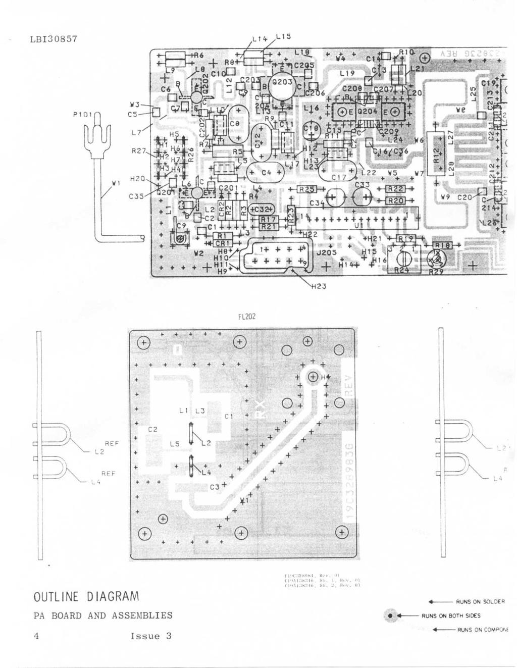
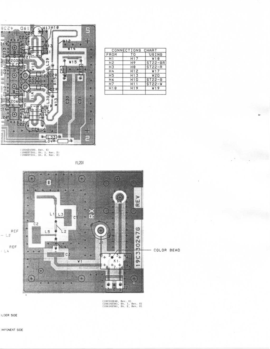
1 MAINTENANCE MANUAL MHz, 35 WATT POWER AMPLIFIER ASSEMBLY 19D430488G1, 2 DESCRIPTION The power amplifier assembly for MASTR II uses six RF power transistors to provide a maximum of 35 Watts output power, R24 located on the PA module, is used to ad j ust the output power to any level from 7 Watts to rated RF power output. The power control circuit consists of R24, Q207, Power Control IC (U1), and a directional coupler. SUPPLY VOLTAGE AND METERING Supply voltage is connected through power leads from the system board to feedthrough capacitor C219. C219 prevents RF from getting on the power leads. Centralized metering jack J205 is provided for use with GE Test Model 4EX3A11 or Test Kit 4EX8K12. The test set meters the AMPL-1 DRIVE (exciter output), the POWER CONTROL voltage, and the DRIVER AND PA CURRENT. PA ASSEMBLY CIRCUIT ANALYSIS The exciter output is coupled through a 50 ohm RF cable to the PA input connector P101. The RF input is coupled through a matching network composed of C2, C3, L1, L2 and L3 to the base of power amplifier Q201. through coupling capacitor CS, and a matching network consisting of C6, C7 L6 and L7. Collector voltage to Q202 is controlled by power control IC (U1), and Q207 and is applied through a collector stabilizing network L11 and R7 and collector feed network C202 and L10. The output of Q202 is coupled to the base of power amplifier Q203 through C9 and the matching network of C203, C204, CIO, L13, L14 and L15. The collector voltage to Q203 is coupled directly from the supply voltage through collector stabilizing network L17 and R9 and collector feed network L16 and C11. The output of Q203 is coupled through an impedance matching network (C206, C13, C207, C208, L18, L19, L20 and L21) and a 50 ohm microstrip W4 that matches the output impedance of Q203 to the input impedance of driver Q204. The collector voltage of Q204 is coupled through R26 from the supply voltage, through collector stabilizing network L23 and R11 through collector feed network L22 and C15. Collector current for Q204 is metered across tapped manganin resistor R26. The reading, taken in position "F" on the 10 Volt scale of the Test Set with the High Sensitivity button pressed, should be approximately 2.1 Amperes. Part of the RF input is rectified by CR1 and metered at J through resistor R21. The rectified RF is also applied to the power control IC (L1). Collector voltage to Q201 is applied from the power controller through collector stabilizing network L5 and R4 and collector feed network L4 and C201. The output of Q201 is coupled to the base of the second power amplifier Q202 GENERAL ELECTRIC
2 LBI CIRCUIT ANALYSIS The output of Q204 is coupled through an impedance matching network (C209, C210, C36 and L24) and a 50 ohm microstrip, W5, to a power splitter consisting of micro strip transmission line W6-W9 and R12. RF output power from Q204 (approximately 12 Watts) is split evenly between two identical class C power amplifiers Q205 and Q206 via their respective identical impedance matching networks. The impedance matching networks consist of C19, C211, C213, L27, L25 and C20, C212, C214, L26 and L28. Collector voltage for Q205 and Q206 is supplied from the A+ line at C219-1 through identical collector stabilizing networks consisting of R13, L31, C23 and L32, R14 and C24 respectively. Collector current for Q205 and Q206 is metered across tapped manganin resistor R27. The reading taken in position G on the 10 volt scale with the HIGH SENS button on the test set pressed. The meter reading should be 7.9 Amperes. The output of Q205 and Q206 is coupled through identical impedance matching and RF power combining networks. The RF power combiner consists of micro strip transmission lines W12 and W13 and resistor 15. The combiner adds the outputs of Q205 and Q206 and applies the combined RF output to the low pass filter through 50 ohm micro strip W14. The RF power output is applied to antenna connector J202 through 50 ohm micro strip W1 in the low pass filter, to the antenna relay or to J202. POWER CONTROL CIRCUIT The Power Control Circuit, consists of CR1, U1, Q207 and the directional coupler (C30, C31, CR3, R16 and W15 ). When the transmitter is keyed, rectified RF from CR1 is applied to a transistorized switch in the Power Control IC (U1), turning on the switch. The switch operates a voltage regulator. The directional coupler senses the forward power at the output of the power amplifier and feeds voltage back to the Power Control IC, resulting in feedback control of the voltage regulator output. A constant voltage is fed via pin 4 of U1 to Power Adjust potentiometer R24. The setting of R24 determines the voltage fed to the base and collector of Q201 and the collector of Q202. Reducing the supply voltage to these stages reduces the drive to the remaining stages of the power amplifier, thereby reducing the power output of the PA. Overvoltage sensing of the supply voltage via pin 11 of U1 shuts down the driver when this condition occurs, thus protecting the driver and PA stages. The feedback power control performs the function of power leveling of the amplifier output over a range of varying input conditions such as drive level, DC voltage and load variations. R29 is provided to limit the maximum power delivered to the antenna to prevent the probability of PA burn up due to misadjustment for excessive power. R29 is set to provide RF output 1 db greater than rated power.
3
4
5
6
7
8
9
10
11
12
13
14
MAINTENANCE MANUAL MDX POWER AMPLIFIER BOARDS 19D904792G2 ( MHz) 19D904792G1 ( MHz) 19D904792G3 ( MHz)
 19D904792G1 ( MHz) 19D904792G3 ( MHz)") MAINTENANCE MANUAL MDX POWER AMPLIFIER BOARDS 19D904792G2 (403-440 MHz) 19D904792G1 (440-470 MHz) 19D904792G3 (470-512 MHz) TABLE OF CONTENTS Page DESCRIPTION... 1 CIRCUIT ANALYSIS... 1 SERVICE NOTES...
MAINTENANCE MANUAL MDX POWER AMPLIFIER BOARDS 19D904792G2 (403-440 MHz) 19D904792G1 (440-470 MHz) 19D904792G3 (470-512 MHz) TABLE OF CONTENTS Page DESCRIPTION... 1 CIRCUIT ANALYSIS... 1 SERVICE NOTES...
Maintenance Manual LBI-38531G MHz, 110 WATT POWER AMPLIFIER 19D902797G1 DESCRIPTION TABLE OF CONTENTS
 Maintenance Manual LBI-38531G 136-174 MHz, 110 WATT POWER AMPLIFIER 19D902797G1 TABLE OF CONTENTS Page DESCRIPTION.............................................. Front Cover SPECIFICATIONS.................................................
MASTR II AUXILIARY RECEIVER 19D417546G7 & G8 & ANTENNA MATCHING UNITS 19C321150G1-G2. Maintenance Manual LBI-30766L. Mobile Communications
 L Mobile Communications MASTR II AUXILIARY RECEIVER 19D417546G7 & G8 & ANTENNA MATCHING UNITS 19C321150G1-G2 Printed in U.S.A Maintenance Manual TABLE OF CONTENTS Page SPECIFICATIONS.....................................................
LBI-30704N MAINTENANCE MANUAL 10-VOLT REGULATOR/CONTROL BOARD 19D417401G1 & 2 DESCRIPTION CIRCUIT ANALYSIS TABLE OF CONTENTS
 LBI-30704N MAINTENANCE MANUAL 10-VOLT REGULATOR/CONTROL BOARD 19D417401G1 & 2 TABLE OF CONTENTS PAGE DESCRIPTION... Cover page CIRCUIT ANALYSIS... Cover page PARTS LIST... 1 OUTLINE DIAGRAM... 4 SCHEMATIC
MAINTENANCE MANUAL. MDX POWER AMPLIFIER BOARDS 19D904792G2 ( MHz) 19D904792G1 ( MHz) 19D904792G3 ( MHz) TABLE OF CONTENTS
 19D904792G1 ( MHz) 19D904792G3 ( MHz) TABLE OF CONTENTS") LBI-39051C MAINTENANCE MANUAL MDX POWER AMPLIFIER BOARDS 19D904792G2 (403-440 MHz) 19D904792G1 (440-470 MHz) 19D904792G3 (470-512 MHz) TABLE OF CONTENTS Page DESCRIPTION... 1 CIRCUIT ANALYSIS... 1 SERVICE
LBI-39051C MAINTENANCE MANUAL MDX POWER AMPLIFIER BOARDS 19D904792G2 (403-440 MHz) 19D904792G1 (440-470 MHz) 19D904792G3 (470-512 MHz) TABLE OF CONTENTS Page DESCRIPTION... 1 CIRCUIT ANALYSIS... 1 SERVICE
MAINTENANCE MANUAL TRANSMITTER/RECEIVER BOARD CMN-234A/B FOR MLSU141 & MLSU241 UHF MOBILE RADIO TABLE OF CONTENTS
 MAINTENANCE MANUAL TRANSMITTER/RECEIVER BOARD CMN-234A/B FOR MLSU141 & MLSU241 UHF MOBILE RADIO TABLE OF CONTENTS DESCRIPTION... 2 CIRCUIT ANALYSIS... 2 TRANSMITTER... 2 9-Voft Regulator... 2 Exciter...
Maintenance Manual INTERNAL BATTERY STANDBY CHARGER OPTION BC01 (9669), 9670 AND 9771 (FOR MASTR II STATIONS) Mobile Communications LBI-30869L
, 9670 AND 9771 (FOR MASTR II STATIONS) Mobile Communications LBI-30869L") L Mobile Communications INTERNAL BATTERY STANDBY CHARGER OPTION BC01 (9669), 9670 AND 9771 (FOR MASTR II STATIONS) Printed in U.S.A. Maintenance Manual TABLE OF CONTENTS Page DESCRIPTION...................................................
L Mobile Communications INTERNAL BATTERY STANDBY CHARGER OPTION BC01 (9669), 9670 AND 9771 (FOR MASTR II STATIONS) Printed in U.S.A. Maintenance Manual TABLE OF CONTENTS Page DESCRIPTION...................................................
Maintenance Manual TRANSMITTER/RECEIVER BOARD CMN-233 FOR MLSH041
 Maintenance Manual TRANSMITTER/RECEIVER BOARD CMN-233 FOR MLSH041 TABLE OF CONTENTS Page DESCRIPTION... 2 CIRCUIT ANALYSIS... 2 Transmitter... 2 9-volt Regulator... 2 Exciter... 2 40-Watt PA... 2 Antenna
PA FAN PLATE ASSEMBLY 188D6127G1 SYMBOL PART NO. DESCRIPTION. 4 SBS /10 Spring nut. 5 19A702339P510 Screw, thread forming, flat head.
 MAINTENANCE MANUAL 851-870 MHz, 110 WATT POWER AMPLIFIER 19D902797G5 TABLE OF CONTENTS Page DESCRIPTION.............................................. Front Page SPECIFICATIONS.................................................
LBI-4938C. Mobile Communications MASTR II POWER AMPLIFIER MODELS 4EF4A1,2,3. Printed in U.S.A. Maintenance Manual
 C Mobile Communications MASTR II POWER AMPLIFIER MODELS 4EF4A1,2,3 Printed in U.S.A. Maintenance Manual TABLE OF CONTENTS DESCRIPTION.................................................... 1 CIRCUIT ANALYSIS.................................................
MASTR II BASE STATION MHz RECEIVER IF/AUDIO/SQUELCH & RF ASSEMBLY (25 khz/12.5 khz CHANNEL SPACING) Maintenance Manual LBI-38506A
 Maintenance Manual LBI-38506A") A Mobile Communications MASTR II BASE STATION 806-824 MHz RECEIVER IF/AUDIO/SQUELCH & RF ASSEMBLY (25 khz/12.5 khz CHANNEL SPACING) TABLE OF CONTENTS RF ASSEMBLY, MIXER AND IF FILTER BOARD...... LBI-30482
A Mobile Communications MASTR II BASE STATION 806-824 MHz RECEIVER IF/AUDIO/SQUELCH & RF ASSEMBLY (25 khz/12.5 khz CHANNEL SPACING) TABLE OF CONTENTS RF ASSEMBLY, MIXER AND IF FILTER BOARD...... LBI-30482
1 FUNCTIONAL DESCRIPTION WAY SPLITTER/INPUT BOARD FET RF AMPLIFIERS WAY POWER COMBINER VSWR CONTROL BOARD...
 CONTENTS 1 FUNCTIONAL DESCRIPTION...1 2 4-WAY SPLITTER/INPUT BOARD...2 3 FET RF AMPLIFIERS...3 4 4-WAY POWER COMBINER...4 5 VSWR CONTROL BOARD...5 6 ADJUSTMENT OF BIAS VOLTAGE TO ESTABLISH PROPER QUIESCENT
ericssonz LBI-38640E MAINTENANCE MANUAL FOR VHF TRANSMITTER SYNTHESIZER MODULE 19D902780G1 DESCRIPTION
 MAINTENANCE MANUAL FOR VHF TRANSMITTER SYNTHESIZER MODULE 19D902780G1 TABLE OF CONTENTS Page DESCRIPTION........................................... Front Cover GENERAL SPECIFICATIONS...................................
ericssonz LBI-39071A MAINTENANCE MANUAL ORION 800 MHz POWER AMPLIFIER UNITS DESCRIPTION
 MAINTENANCE MANUAL ORION 800 MHz POWER AMPLIFIER UNITS 344A4574P1 JHM-871PL 12 WATT 344A4574P2 JHM-871PH 35/30 WATT TABLE OF CONTENTS Page DESCRIPTION................................................ Front
LBI-30398N. MAINTENANCE MANUAL MHz PHASE LOCK LOOP EXCITER 19D423249G1 & G2 DESCRIPTION TABLE OF CONTENTS. Page. DESCRIPTION...
 MAINTENANCE MANUAL 138-174 MHz PHASE LOCK LOOP EXCITER 19D423249G1 & G2 LBI-30398N TABLE OF CONTENTS DESCRIPTION...Front Cover CIRCUIT ANALYSIS... 1 MODIFICATION INSTRUCTIONS... 4 PARTS LIST AND PRODUCTION
MAINTENANCE MANUAL RF BOARD 19D901835G1 ( MHz) 19D901835G2 ( MHz) FOR MVS
 19D901835G2 ( MHz) FOR MVS") D MAINTENANCE MANUAL F BOAD 19D901835G1 (136-153 MHz) 19D901835G2 (150-174 MHz) FO MVS TABLE OF CONTENTS DESCIPTION............................................... Front Cover CICUIT ANALYSIS..............................................
D MAINTENANCE MANUAL F BOAD 19D901835G1 (136-153 MHz) 19D901835G2 (150-174 MHz) FO MVS TABLE OF CONTENTS DESCIPTION............................................... Front Cover CICUIT ANALYSIS..............................................
ERICSSONZ LBI-30398P. MAINTENANCE MANUAL MHz PHASE LOCKED LOOP EXCITER 19D423249G1 & G2 DESCRIPTION TABLE OF CONTENTS
 MAINTENANCE MANUAL 138-174 MHz PHASE LOCKED LOOP EXCITER 19D423249G1 & G2 TABLE OF CONTENTS Page DESCRIPTION... Front Cover CIRCUIT ANALYSIS...1 MODIFICATION INSTRUCTIONS...4 PARTS LIST...5 PRODUCTION
MAINTENANCE MANUAL MHz, 100 WATT POWER AMPLIFIER 19D901841G2
 D MAINTENANCE MANUAL 851-870 MHz, 100 WATT POWER AMPLIFIER 19D901841G2 TABLE OF CONTENTS Page DESCRIPTION................................................ Front Cover CIRCUIT ANALYSIS.............................................
LBI-31564A. Mobile Communications. DELTA - SX MHz RADIO COMBINATIONS (NEGATIVE GROUND ONLY) Maintenance Manual
 Maintenance Manual") A Mobile Communications DELTA - SX 136-174 MHz RADIO COMBINATIONS (NEGATIVE GROUND ONLY) Maintenance Manual TABLE OF CONTENTS MILITARY AND SYSTEM SPECIFICATIONS................................. 2-3 COMBINATION
A Mobile Communications DELTA - SX 136-174 MHz RADIO COMBINATIONS (NEGATIVE GROUND ONLY) Maintenance Manual TABLE OF CONTENTS MILITARY AND SYSTEM SPECIFICATIONS................................. 2-3 COMBINATION
LBI-31807D. Mobile Communications MASTR II REPEATER CONTROL PANEL 19B234871P1. Maintenance Manual. Printed in U.S.A.
 D Mobile Communications MASTR II REPEATER CONTROL PANEL 19B234871P1 Maintenance Manual Printed in U.S.A. This page intentionally left blank 13 PARTS LIST 12 PARTS LIST LBI-31807 11 PARTS LIST 10 SCHEMATIC
Maintenance Manual. MTD SERIES 900 MHz, 10-WATT, DATA ONLY MOBILE RADIO. Mobile Communications LBI TABLE OF CONTENTS
 Mobile Communications MTD SERIES 900 MHz, 10-WATT, DATA ONLY MOBILE RADIO TABLE OF CONTENTS RF BOARD............................... LBI-38545 AUDIO BOARD............................ LBI-38546 LOGIC BOARD............................
LBI-30705L INSTRUCTIONS FOR AUDIO BOARDS 19A129924G1-G3 DESCRIPTION CIRCUIT ANALYSIS ERICSSONZM ERICSSONZM TABLE OF CONTENTS. Audio Board 19A129924G1
 ERICSSONZM INSTRUCTIONS FOR AUDIO BOARDS 19A129924G1-G3 L TABLE OF CONTENTS Page DESCRIPTION............................................... Front Cover CIRCUIT ANALYSIS............................................
MODERN AM BROADCAST STATIONS AM STEREO CQUAM WITH DDS
 MODERN AM BROADCAST STATIONS AM STEREO CQUAM WITH DDS DDS EXCITER OPERATING MANUAL 20W CARRIER - 80W PEP WHAT IS DDS? IT IS THE INITIALS OF THE WORDS DIRECT DIGITAL SYNTHESIZER. THAT MEANS: DIRECT DIGITAL
MAINTENANCE MANUAL MHz, 100 WATT POWER AMPLIFIER 19D901841G3
 MAINTENANCE MANUAL 851-870 MHz, 100 WATT POWER AMPLIFIER 19D901841G3 TABLE OF CONTENTS SPECIFICATIONS............................................... Front Cover DESCRIPTION.................................................
PA70 Amplifier Operation and Maintenance Manual
 Eclipse Series RF Technology rfinfo@rftechnology.com.au January, 2004 PA70 Amplifier Operation and Maintenance Manual This manual is produced by RF Technology Pty Ltd 10/8 Leighton Place, Hornsby NSW 2077
Construction Manual 6m-Linear-Transverter XV6/10
 Construction Manual 6m-Linear-Transverter XV6/10 Holger Eckardt DF2FQ Kirchstockacherstr. 33 D-85662 Hohenbrunn 2606 Technical data exciter frequency: 28... 30 MHz RF frequency: 50... 52 MHz supply voltage:
MAINTENANCE MANUAL MHz OSCILLATOR-MULTIPLIER BOARD 19D423194G1
 D (DF1106) MAINTENANCE MANUAL 806-825 MHz OSCILLATOR-MULTIPLIER BOARD 19D423194G1 TABLE OF CONTENTS Page DESCRIPTION................................................. Front Cover CIRCUIT ANALYSIS.............................................
MAINTENANCE MANUAL MHz, 100 WATT POWER AMPLIFIER 19D901841G3
 A MAINTENANCE MANUAL 851-870 MHz, 100 WATT POWER AMPLIFIER 19D901841G3 TABLE OF CONTENTS SPECIFICATIONS............................................... Front Cover DESCRIPTION.................................................
LBI-38642B. MAINTENANCE MANUAL RECEIVER FRONT END MODULE 19D902782G1: MHz 19D902782G2: MHz DESCRIPTION TABLE OF CONTENTS
 LBI-38642B MAINTENANCE MANUAL RECEIVER FRONT END MODULE 19D902782G1: 136-151 MHz 19D902782G2: 150-174 MHz TABLE OF CONTENTS Page DESCRIPTION............................................... Front Cover SPECIFICATIONS.............................................
Technician Licensing Class
 Technician Licensing Class Go Picture Presented These! by Amateur Radio Technician Class Element 2 Course Presentation ELEMENT 2 SUB-ELEMENTS (Groupings) About Ham Radio Call Signs Control Mind the Rules
MAINTENANCE MANUAL AUDIO AMPLIFIER BOARD 19D904025G1 (MDR) AUDIO AMPLIFIER BOARD 19D904025G2 (MDX)
 AUDIO AMPLIFIER BOARD 19D904025G2 (MDX)") A MAINTENANCE MANUAL AUDIO AMPLIFIER BOARD 19D904025G1 (MDR) AUDIO AMPLIFIER BOARD 19D904025G2 (MDX) TABLE OF CONTENTS DESCRIPTION............................................... Page Front Cover CIRCUIT
A MAINTENANCE MANUAL AUDIO AMPLIFIER BOARD 19D904025G1 (MDR) AUDIO AMPLIFIER BOARD 19D904025G2 (MDX) TABLE OF CONTENTS DESCRIPTION............................................... Page Front Cover CIRCUIT
LBI-30029M. MAINTENANCE MANUAL MHz OSCILLATOR/MULTIPLIER BOARD 19D423266G1-G10 DESCRIPTION CIRCUIT ANALYSIS TABLE OF CONTENTS. ICOMs.
 M MAINTENANCE MANUAL 406-512 MHz OSCILLATOR/MULTIPLIER BOARD 19D423266G1-G10 TABLE OF CONTENTS Page DESCRIPTION.............................................. CIRCUIT ANALYSIS..........................................
LBI-38849F MAINTENANCE MANUAL RF BOARD 19D902123G22 DESCRIPTION CIRCUIT ANALYSIS TABLE OF CONTENTS SYNTHESIZER CIRCUIT. Page
 MAINTENANCE MANUAL RF BOARD 19D902123G22 TABLE OF CONTENTS DESCRIPTION............................................ Front Cover CIRCUIT ANALYSIS......................................... Front Cover SYNTHESIZER
Construction Manual 4m-Linear-Transverter XV4-15
 Construction Manual 4m-Linear-Transverter XV4-15 Holger Eckardt DF2FQ Kirchstockacherstr. 33 D-85662 Hohenbrunn 3207 Technical data exciter frequency: 21.0... 21.5 MHz RF frequency: 70.0.. 70.5 MHz supply
Maintenance Manual. ORION UHF (Dual Bandwidth) SCAN AND SYSTEM MOBILE RADIO. ericssonz LBI TABLE OF CONTENTS
 SCAN AND SYSTEM MOBILE RADIO. ericssonz LBI TABLE OF CONTENTS") Maintenance Manual ORION UHF (Dual Bandwidth) SCAN AND SYSTEM MOBILE RADIO TABLE OF CONTENTS Synthesizer/Receiver/Exciter....... LBI-39163 Power Amplifier.............. LBI-39164 PA Interface................
Maintenance Manual ORION UHF (Dual Bandwidth) SCAN AND SYSTEM MOBILE RADIO TABLE OF CONTENTS Synthesizer/Receiver/Exciter....... LBI-39163 Power Amplifier.............. LBI-39164 PA Interface................
ericssonz LBI-38642C MAINTENANCE MANUAL RECEIVER FRONT END MODULE 19D902782G1: MHz 19D902782G2: MHz DESCRIPTION TABLE OF CONTENTS
 LBI-38642C MAINTENANCE MANUAL RECEIVER FRONT END MODULE 19D902782G1: 136-151 MHz 19D902782G2: 150-174 MHz TABLE OF CONTENTS Page DESCRIPTION............................................... Front Cover SPECIFICATIONS.............................................
c. Battery Charger c Volt Supply TL MICROWAVE RADIO DESCRIPTION POWER SUPPLY H. Battery Voltage Alarm Circuit.
 BELL SYSTEM PRACTCES Plant Series 2. OPERATNG PRNCPLES CONTENTS PAGE B. Klystron Supply Regulator and nverter. D. Battery Voltage Alarm Circuit. 3. CRCUT DESCRPTON. A. Klystron Supply Regulator and nverter.
A 100-Watt Transmitter Using a Pair of VT1625s
 12/16/2007 6:00 PM VT1625 100 Watt Transmitter A 100-Watt Transmitter Using a Pair of VT1625s FIG. 10.6 A 100-watt transmitter for five bands, using salvaged TV power transformer and surplus 1625 amplifier
Users Manual. 200W HF/50MHz Band Auto Antenna Tuner. Model HC-200AT
 Users Manual 200W HF/50MHz Band Auto Antenna Tuner Model HC-200AT Caution 1. Never remove or open the tuner cover while transmitting. When there is RF in the circuits of the tuner, there will be high voltage
AVL-10000T AUDIO VIDEO LINK TRANSMITTER TECHNICAL MANUAL
 AVL-10000T AUDIO VIDEO LINK TRANSMITTER TECHNICAL MANUAL Document : AVL-10000T Version: 1.00 Author: Henry S Date: 25 July 2008 This module contains protection circuitry to guard against damage due to
PAiA 4780 Twelve Stage Analog Sequencer Design Analysis Originally published 1974
 PAiA 4780 Twelve Stage Analog Sequencer Design Analysis Originally published 1974 DESIGN ANALYSIS: CLOCK As is shown in the block diagram of the sequencer (fig. 1) and the schematic (fig. 2), the clock
WARNING: DO NOT PROCEED WITHOUT READING THIS PAGE.
 WARNING: DO NOT PROCEED WITHOUT READING THIS PAGE. The B-1030-G produces at least 300 watts of VHF R.F. power and is not to be taken lightly. Severe R.W. burns can be sustained at this power level! Power
Vectronics VC-300D DIGITAL BARGRAPH ANTENNA TUNER
 Vectronics VC-300D DIGITAL BARGRAPH ANTENNA TUNER FEATURES The Vectronics VC-300D Antenna Tuner optimizes the performance of your antenna and transmitter, receiver, or transceiver by providing adjustable
SERVICE MANUAL GENERAL The Solid State Stereo Amplifier, Type TSAlO is. Page 1. SOLID STATE STEREO AMPLIFIER, Type TSAlO
 -- - -i SERVICE MANUAL 40-30 Page 1 TRP Figure 1. Solid State Stereo Amplifier, Type TSA10. 1. GENERAL The Solid State Stereo Amplifier, Type TSAlO is a fully transistorized, dual channel, low distortion,
Hi-Fi Headphone Amplifier
 Hi-Fi Headphone Amplifier Contributed by Richard Crowley (Additional Notes by Rod Elliott) This design for a headphone amplifier arose after the purchase of commercial equipment with separate pre and power
FCC Technician License Course
 FCC Technician License Course 2014-2018 FCC Element 2 Technician Class Question Pool Presented by: Tamiami Amateur Radio Club (TARC) WELCOME To the SECOND of 4, 3-hour classes presented by TARC to prepare
WARNING: DO NOT PROCEED WITHOUT READING THIS PAGE.
 WARNING: DO NOT PROCEED WITHOUT READING THIS PAGE. The B-2530-G produces at least 300 watts of VHF R.F. power and is not to be taken lightly. Severe R.W. burns can be sustained at this power level! Power
 KILOWATT GROUNDED-GRID LINEAR AMPLIFIER (Radiotron HB) Grounded-grid amplifiers The input voltage is applied to the cathode, the grid is earthed, and the output is taken from the plate, being in phase
Techniques for Passive Circuit Analysis for. State Space Differential Equations
 Techniques for Passive Circuit Analysis for chp4 1 State Space Differential Equations 1. Draw circuit schematic and label components (e.g., R 1, R 2, C 1, L 1 ) 2. Assign voltage at each node (e.g., e
LED level meter driver, 12-point, linear scale, dot or bar display
 LED level meter driver, 12-point, linear scale, dot or bar display The is a monolithic IC for LED level meter applications. The display level range is 0mVrms to 300mVrms (typ.) divided into 12 equally-spaced
The ROSE 80 CW Transceiver (Part 1 of 3)
") Build a 5 watt, 80 meter QRP CW Transceiver!!! Page 1 of 10 The ROSE 80 CW Transceiver (Part 1 of 3) Build a 5 watt, 80 meter QRP CW Transceiver!!! (Designed by N1HFX) A great deal of interest has been
Build a 5 watt, 80 meter QRP CW Transceiver!!! Page 1 of 10 The ROSE 80 CW Transceiver (Part 1 of 3) Build a 5 watt, 80 meter QRP CW Transceiver!!! (Designed by N1HFX) A great deal of interest has been
DEM TC DEM TRANSVERTER CONTROL
 DEM TC DEM TRANSVERTER CONTROL The DEM Transverter Control (DEM TC) is the circuit board that controls all transverter functions in the DEMI 2.3 GHz. -10 GHz. transverters. It was designed with many options
Building a Bitx20 Version 3
 Building a Bitx20 Version 3 The board can be broken into sections and then built and tested one section at a time. This will make troubleshooting easier as any problems will be confined to one small section.
Transmission Line Signal Sampling By Don Steinbach, AE6PM
 Transmission Line Signal Sampling By Don Steinbach, AE6PM When I was finalizing the mechanical layout of my remotely-operated 3-position coaxial antenna switch (Fig. 1), I wanted to include a way to bring
PLUG N PLAY WATT DIGITAL FM TRANSMITTER. April, 2002 IM No
 PLUG N PLAY 1000 1000 WATT DIGITAL FM TRANSMITTER April, 2002 IM No. 597 9972 OPERATION/FEATURE PROGRAMMING. The PNP 1000 allows the user to select many types of different operating parameters and features.
FREQUENCY AGILE FM MODULATOR INSTRUCTION BOOK IB
 FMT615C FREQUENCY AGILE FM MODULATOR INSTRUCTION BOOK IB1215-02 TABLE OF CONTENTS SECTION SUBJECT 1.0 Introduction 2.0 Installation & Operating Instructions 3.0 Specification 4.0 Functional Description
Model AAA-1C. Addendum to AAA-1B documentation
 Model AAA-1C. Addendum to AAA-1B documentation 1. Specifications for Model AAA-1C (11) General Output impedance Power supply (1) Maximal output voltage (10) Physical size 50 Ohms, BNC connector on control
MODERN AM BROADCAST STATIONS
 MODERN AM BROADCAST STATIONS With DDS DDS EXCITER OPERATING MANUAL 75w carrier - 300w p.e.p What is DDS IT IS THE INITIALS OF THE WORDS DIRECT DIGITAL SYNTHESIZER, THAT MEANS: DIRECT DIGITAL FREQUENCY
FM RADIO KIT ESSENTIAL INFORMATION. Version 2.0 GET IN TUNE WITH THIS
 ESSENTIAL INFORMATION BUILD INSTRUCTIONS CHECKING YOUR PCB & FAULT-FINDING MECHANICAL DETAILS HOW THE KIT WORKS GET IN TUNE WITH THIS FM RADIO KIT Version 2.0 Build Instructions Before you start, take
Various circuit architectures for distribution amplifiers
 Copyright C.P. Steinmetz 2015 Various circuit architectures for distribution amplifiers This guide refers to the four schematic diagrams on the following page. It addresses distribution amplifier architectures
Maintenance Manual ERICSSONZ LBI-31552E
 E Maintenance Manual TONE REMOTE CONTROL BOARD 19A704686P4 (1-Frequency Transmit Receive with Channel Guard) 19A704686P6 (4-Frequency Transmit Receive with Channel Guard) ERICSSONZ Ericsson Inc. Private
MAINTENANCE MANUAL AUDIO MATRIX BOARD P29/
 MAINTENANCE MANUAL AUDIO MATRIX BOARD P29/5000056000 TABLE OF CONTENTS Page DESCRIPTION................................................ Front Cover CIRCUIT ANALYSIS.............................................
MAINTENANCE MANUAL MHz OSCILLATOR/MULTIPLIER BOARD 19D423078G1-G8
 MAINTENANCE MANUAL 25-50 MHz OSCILLATOR/MULTIPLIER BOARD 19D423078G1-G8 G (DF1106) (DF1119 IMTS) TABLE OF CONTENTS Page DESCRIPTION.............................................. Front Cover CIRCUIT ANALYSIS...........................................
LBI-31899G DESCRIPTION AND MAINTENANCE MASTR II BASE STATION COMBINATIONS TABLE OF CONTENTS ILLUSTRATIONS
 DESCRIPTION AND MAINTENANCE MASTR II BASE STATION COMBINATIONS TABLE OF CONTENTS Page SPECIFICATIONS............................................ 1 FCC FILING NUMBERS........................................
WARNING! IMPORTANT NOTICE
 WARNING! IMPORTANT NOTICE FCC type acceptance requirments prohibit sales of amplifiers operating below 144 MHz with internal RF sensing circuits that place the amplifier in a transmit mode. Because of
KWM-2/2A Transceiver THE COLLINS KWM-2/2A TRANSCEIVER
 KWM-2/2A Transceiver Click the photo to see a larger photo Click "Back" button on browser to return Courtesy of Norm - WA3KEY THE COLLINS KWM-2/2A TRANSCEIVER Unmatched for versatility, dependability and
SMR Manual Revision 1
 SMR 6868 Manual Revision 1 QUANTAR Instruction Manual for: Quantar Digital-Capable Station for Conventional, SECURENET, ASTRO, 6809 Trunking, and IntelliRepeater Systems This SMR applies to manual revision
MFJ-834 RF Ammeter. Introduction. Uses
 MFJ-834 RF Ammeter Introduction Congratulations on purchasing the MFJ-834 RF Ammeter. The MFJ-834 is designed for measuring in-line RF feedline current on 1.8-30 MHz while having low interaction on the
MAINTENANCE MANUAL AUDIO BOARDS 19D902188G1, G2 & G3
 B MAINTENANCE MANUAL AUDIO BOARDS 19D902188G1, G2 & G3 TABLE OF CONTENTS Page Front Cover DESCRIPTION............................................... CIRCUIT ANALYSIS............................................
BP-1A. Band-Pass variable filter continuous tuning from 3 to 30MHz. For analogue or software-defined receivers (SDR) Assembly manual
 Assembly manual") BP-1A Band-Pass variable filter continuous tuning from 3 to 30MHz. For analogue or software-defined receivers (SDR) Assembly manual Last updated: December 1, 2017 ea3gcy@gmail.com Updates and news at:
BP-1A Band-Pass variable filter continuous tuning from 3 to 30MHz. For analogue or software-defined receivers (SDR) Assembly manual Last updated: December 1, 2017 ea3gcy@gmail.com Updates and news at:
LBI-38673F MAINTENANCE MANUAL FOR RECEIVER FRONT END MODULE 19D902782G3, G4, & G7 DESCRIPTION TABLE OF CONTENTS
 MAINTENANCE MANUAL FOR 19D902782G3, G4, & G7 TABLE OF CONTENTS Page DESCRIPTION........................................... Front Cover SPECIFICATIONS......................................... 1 CIRCUIT
Setup of Gain Control System (MGC/AGC)
") Setup of Gain Control System (MGC/AGC) Comark Optimum and Ultimate ATSC Transmitters This service bulletin provides the procedure to properly align the manual gain control (MGC) and automatic gain control
Setup of Gain Control System (MGC/AGC) Comark Optimum and Ultimate ATSC Transmitters This service bulletin provides the procedure to properly align the manual gain control (MGC) and automatic gain control
A 500 Broadband Power Amplifier
 A 500 Broadband Power Amplifier HIGH RF VOLTAGES MAY BE PRESENT AT THE OUTPUT OF THIS UNIT. All operating personnel should use extreme caution in handling these voltages and be thoroughly familiar with
LBI-38673C MAINTENANCE MANUAL FOR RECEIVER FRONT END MODULE 19D902782G3, G4, & G7 DESCRIPTION TABLE OF CONTENTS
 LBI-38673C MAINTENANCE MANUAL FOR 19D902782G3, G4, & G7 TABLE OF CONTENTS Page DESCRIPTION........................................... Front Cover SPECIFICATIONS.........................................
MAINTENANCE MANUAL FOR RECEIVER FRONT END MODULE 19D902782G5
 LBI-39028A IC DATA MAINTENANCE MANUAL FOR U1 19A704125P1 Quad Operational Amplifier U30 RYTUA901201/1 Power Module TABLE OF CONTENTS DESCRIPTION................................................ Front Cover
7 Watt Audio Amplifier with TDA2003
 7 Watt Audio Amplifier with TDA2003 Schematic diagram of a simple 7 watt audio amplifier using TDA2003 Amplifier IC. This is a good IC with many built in features like low harmonic distortion, short circuit
MAINTENANCE MANUAL RF BOARD 19D902243G4 ( MHz) 19D902243G5 ( MHz) 19D902243G6 ( MHz) FOR MVS
 19D902243G5 ( MHz) 19D902243G6 ( MHz) FOR MVS") LI-38258D IC DATA MAINTENANCE MANUAL F OAD 19D902243G4 (403-440 MHz) 19D902243G5 (440-470 MHz) 19D902243G6 (470-512 MHz) FO MVS OPEATIONAL AMPLIFIE 19A701789P2 QUAD ILATEAL SWITCH (U202) 19A700029P44 TALE
LI-38258D IC DATA MAINTENANCE MANUAL F OAD 19D902243G4 (403-440 MHz) 19D902243G5 (440-470 MHz) 19D902243G6 (470-512 MHz) FO MVS OPEATIONAL AMPLIFIE 19A701789P2 QUAD ILATEAL SWITCH (U202) 19A700029P44 TALE
MFJ-219/219N 440 MHz UHF SWR Analyzer TABLE OF CONTENTS
 MFJ-219/219N 440 MHz UHF SWR Analyzer TABLE OF CONTENTS Introduction...2 Powering The MFJ-219/219N...3 Battery Installation...3 Operation Of The MFJ-219/219N...4 SWR and the MFJ-219/219N...4 Measuring
DELTA-S. Maintenance Manual. NARROW BAND, SYNTHESIZED MHz Mobile Communications (NEGATIVE GROUND ONLY) Mobile Communications LBI-31567
 Mobile Communications LBI-31567") Mobile Communications 65-110 WATT MBILE RADI DELTA-S NARRW BAND, SYNTHESIZED 403-430-450-512 Mobile Communications (NEGATIVE GRUND NLY) Maintenance Manual TABLE F CNTENTS MILITARY SPECIFICATINS..........................................
Mobile Communications 65-110 WATT MBILE RADI DELTA-S NARRW BAND, SYNTHESIZED 403-430-450-512 Mobile Communications (NEGATIVE GRUND NLY) Maintenance Manual TABLE F CNTENTS MILITARY SPECIFICATINS..........................................
Hydra: A Three Stage Power Converter
 6.101 Project Proposal Paul Hemberger, Joe Driscoll, David Yamnitsky Hydra: A Three Stage Power Converter Introduction Hydra is a three stage power converter system where each stage not only supports a
1140LA Broadband Power Amplifier
 1140LA Broadband Power Amplifier HIGH RF VOLTAGES MAY BE PRESENT AT THE OUTPUT OF THIS UNIT. All operating personnel should use extreme caution in handling these voltages and be thoroughly familiar with
ALX-SSB 5 Band Filter Assembly Manual 19 November 2018
 ALX-SSB 5 Band Filter Assembly Manual 19 November 2018 Contents Theory of Operation:... 1 Figure 1... 2 Parts Included:... 4 Board Overview:... 5 Figure 2... 5 Figure 3... 5 Board Assembly:... 6 Cable
Maintenance Manual CHANNEL GUARD ENCODER/DECODER 19D430740G1 TONE REJECT FILTER 19D430740G4. Mobile Communications
 E ********* (REPLACES LBI-4143) Mobile Communications CHANNEL GUARD ENCODER/DECODER 19D430740G1 TONE REJECT FILTER 19D430740G4 Printed in U.S.A. Maintenance Manual TABLE OF CONTENTS SPECIFICATIONS..................................................
Bitx Version 3 Linear Amplifier Assembly
 Bitx Version 3 Linear Amplifier Assembly The power supply section has 2 options. 1 - AC input and a higher voltage on the IRF510 and +12 volts to the bitx. 2 - +12 volts applied to both the final and the
RF Power Amplifier (RFPA) Designing a 'Output Tank Circuit'
 Designing a 'Output Tank Circuit'") RF Power Amplifier (RFPA) Designing a 'Output Tank Circuit' By Larry E. Gugle K4RFE, RF Design, Manufacture, Test & Service Engineer (Retired) Figure-1 Output 'Tank' Circuit Network in Low-Pass Filter
RF Power Amplifier (RFPA) Designing a 'Output Tank Circuit' By Larry E. Gugle K4RFE, RF Design, Manufacture, Test & Service Engineer (Retired) Figure-1 Output 'Tank' Circuit Network in Low-Pass Filter
XR12. Frequency Change Procedure IS Issue August 2007
 XR12 Frequency Change Procedure IS07013 Issue 1.0... 31 August 2007 Nautel Limited 10089 Peggy's Cove Road, Hackett's Cove, NS, Canada B3Z 3J4 T.877 6 nautel (628835) or +1.902.823.2233 F.+1.902.823.3183
HAM RADIO. 1 KW SSPA 144 MHz RF POWER AMPLIFIER SWR 65:1
 AMD 1000 AR 144 November 2011 First Edition HAM RADIO 1 KW SSPA 144 MHz RF POWER AMPLIFIER SWR 65:1 RF Dispositive : MRF6VP61K25HR6 Freescale Frequency Range 142-146 MHz 4 W Input ± 0.5 W ( @ 1 KW Carrier
Technical Service Bulletin DCX AGC Setup Procedure for ADAPT IV Exciters
 Technical Service Bulletin 110427 DCX AGC Setup Procedure for ADAPT IV Exciters This service bulletin provides the procedure to properly install and align the total system automatic gain control (AGC)
3100LA Broadband Power Amplifier
 3100LA Broadband Power Amplifier HIGH RF VOLTAGES MAY BE PRESENT AT THE OUTPUT OF THIS UNIT. All operating personnel should use extreme caution in handling these voltages and be thoroughly familiar with
Definitions of Technical Terms
 Definitions of Technical Terms Terms Ammeter Amperes, Amps Band Capacitor Carrier Squelch Diode Dipole Definitions How is an ammeter usually connected = In series with the circuit What instrument is used
A01-eNETL2TUV_Manual_RevH.doc. GE MDS enetl2t/u/v Manual P/N A01 Rev H
 GE MDS enetl2t/u/v Manual P/N 05-4186A01 Rev H 05-4186A01 Rev H Page 1 of 7 12/19/2016 Table of Contents 1 Important Information... 3 1.1 RF Exposure... 3 1.2 FCC Approval Notice... 3 1.3 FCC Part 80 Information...
5/1.0 kw AM Transmitter
 5/1.0 kw AM Transmitter Collins' 820E /F -1 series of broadcast transmitters is one of the most extensively transistorized series of transmitters available in the 5 -kw to 10 -kw power range. The series
Basic Electronics. Chapter 2, 3A (test T5, T6) Basic Electrical Principles and the Functions of Components. PHYS 401 Physics of Ham Radio
 Basic Electrical Principles and the Functions of Components. PHYS 401 Physics of Ham Radio") Basic Electronics Chapter 2, 3A (test T5, T6) Basic Electrical Principles and the Functions of Components Figures in this course book are reproduced with the permission of the American Radio Relay League.
Basic Electronics Chapter 2, 3A (test T5, T6) Basic Electrical Principles and the Functions of Components Figures in this course book are reproduced with the permission of the American Radio Relay League.
ADDENDUM NUMBER 2 TO MAINTENANCE MANUAL LBI-38642D Refer to ECO# RECEIVER FRONT END PWB 19D902490G1 (19D902490, Sh. 1, Rev.
 ADDENDUM NUMBER 2 TO MAINTENANCE MANUAL Refer to ECO#20026373 RECEIVER FRONT END PWB 19D902490G1 (19D902490, Sh. 1, Rev. 9) 1 ADDENDUM NUMBER 2 TO MAINTENANCE MANUAL Refer to ECO#20026373 RECEIVER FRONT
Broadcast Concepts Inc NW 102 Road Suite 4 Medley FL Tel: : Fax Model P50FM42MH-SMA2 FM Pallet Amplifier Module
 Model P50FM42MH-SMA2 FM Pallet Amplifier Module This amplifier module is ideal for driver stages in FM Broadcast transmitters. 86 110MHz 28Volts Pout: 50W CW minimum 40dB Gain Class AB MACOM MRF173 Mosfet
HAMTRONICS TB901 FM EXCITER INSTALLATION, OPERATION, & MAINTENANCE
 HAMTRONICS TB901 FM EXCITER INSTALLATION, OPERATION, & MAINTENANCE GENERAL INFORMATION. The TB901 is a single-channel low power fm transmitter (exciter) designed to provide 300-600 milliwatts continuous
2100L Broadband Power Amplifier
 2100L Broadband Power Amplifier HIGH RF VOLTAGES MAY BE PRESENT AT THE OUTPUT OF THIS UNIT. All operating personnel should use extreme caution in handling these voltages and be thoroughly familiar with
RF3376 General Purpose Amplifier
 General Purpose Amplifier RF3376 General Purpose Amplifier Package Style: SOT8 Features DC to >6000MHz Operation Internally Matched Input and Output 22dB Small Signal Gain +2.0dB Noise Figure +11dBm Output
Pacific Antenna Easy Transmitter Kit
 Pacific Antenna Easy Transmitter Kit Introduction The Easy Transmitter kit from qrpkits.com provides a crystal controlled transmitter with VXO tuning. The circuit consists of a N3904 based crystal oscillator
Fluorescent display tube level meter driver, 16-point 2 channel, VU scale, bar display
 Fluorescent display tube level meter driver, 16-point 2 channel, VU scale, bar display The is a two-channel, 16-point fluorescent display tube driver for VU-scale bar-level meters. It uses a dynamic-drive