Fundamentals of Remote Sensing: the Imaging RADAR System
|
|
|
- Beryl Long
- 6 years ago
- Views:
Transcription


1 INSIS Fundamentals of Remote Sensing: the Imaging RADAR System Notions fondamentales de télédétection : le RADAR imageur Gabriel VASILE Chargé de Recherche CNRS gabriel.vasile@gipsa-lab.grenoble-inp.fr 1 Why use RADAR for remote sensing? Controllable source of illumination sees through cloud and rain, and at night Images can be high resolution 1 m 10 m with spaceborne platforms 0.1 m 0.2 m with airborne platforms Different features are portrayed or discriminated compared to visible sensors Some surface features can be seen better in radar images ice, ocean waves soil moisture, vegetation mass man-made objects, e.g. buildings geological structures 2


2 Singapore Harbour Enlargement of central ship 3 Antarctic Mapping The Erebus ice tongue 4


3 Help! A huge oil slick is approaching the coast! Mediterranean Sea 5 Oil Spill Monitoring: the southern Vietnamese coast CNES 2000 ESA 2000 Note that dark zones directly at the coast line are caused by wind shadow, not oil! 6


 of the return signals provides its own")
4 Deforestation Mapping : optical and radar sensors Optical and Radar scenes of forest clear cutting. 7 What is RADAR? Radar GRAVES (emitting site) RADAR is an acronym for RAdio Detection And Ranging Armée de l Air, 2005 Radar GRAVES (reception site) 8 3 primary functions: transmits microwave (radio) signals towards a scene receives the portion of the transmitted energy backscattered from the scene observes the strength (detection) and the time delay (ranging) of the return signals provides its own energy source active remote sensing system


5 Transmission EM spectrum of the Earth s atmosphere 9 Electromagnetic Spectrum All electromagnetic waves propagate at the speed of light X-rays, visible light, radio waves Described by variations in their electric and magnetic fields Characterized by polarization, and by frequency or wavelength (inversely proportional to frequency) Radar remote sensing the microwave portion of the electromagnetic spectrum, from a frequency of 0.3 GHz to 300 GHz, or in wavelength terms, from 1 m to 1 mm. 10
. Used in many spaceborne SARs, such as ERS-1 and RADARSAT. S-band: from 7.")

 As an imaging side-looking radar moves along its path, it accumulates data.")
6 Relative Size of Microwave Wavelengths Microwave frequencies have been arbitrarily assigned to bands identified by letters: X-band: from 2.4 to 3.75 cm (12.5 to 8 GHz). Widely used for military reconnaissance and commercially for terrain surveys C-band: from 3.75 to 7.5 cm (8 to 4 GHz). Used in many spaceborne SARs, such as ERS-1 and RADARSAT. S-band: from 7.5 to 15 cm (4 to 2 GHz). Used in Almaz. L-band: from 15 to 30 cm (2 to 1 GHz). Used on SEASAT and JERS-1. P-band: from 30 to 100 cm (1 to 0.3 GHz). Used on NASA/ JPL AIRSAR. Radars operating at wavelengths greater than 2 cm are not significantly affected by cloud cover, however, rain does become a factor at wavelengths shorter than 4 cm. 11 What is Synthetic Aperture Radar (SAR)? A side-looking radar system which makes a highresolution image of the Earth s surface (for remote sensing applications) As an imaging side-looking radar moves along its path, it accumulates data. In this way, continuous strips of the ground surface are illuminated parallel and to one side of the flight direction. The across-track dimension is referred to as range. Near range edge is closest to nadir (the points directly below the radar) and far range edge is farthest from the radar. The along-track dimension is referred to as azimuth. Digital signal processing is used to focus the image and obtain a higher resolution than achieved by conventional radar 12
 range velocity measurement 13 (Doppler) range velocity measurement Spatial domain: antenna processing (beam forming, antenna pointing) Separation between receiving beam directions angular")
7 Principle of Synthetic Aperture Radar Temporal domain: signal processing (modulation code, correlation) signal echo target detection propagation (delay) time range positioning frequency shift (Doppler) range velocity measurement 13 Principle of Synthetic Aperture Radar Temporal domain: signal processing (modulation code, correlation) signal echo target detection propagation (delay) time range positioning frequency shift (Doppler) range velocity measurement Spatial domain: antenna processing (beam forming, antenna pointing) Separation between receiving beam directions angular positioning 14
 over B Good")


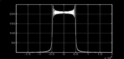
8 Synthetic Aperture Radar: temporal domain Emission: short baseband signal Emission: frequency ramp (chirp) over B Good echolocation inter-correlation: reception - emission Power transmission! correlation peak 1/B range resolution c/2b ERS-1 satellite B = MHz ResR= 9.6 m 15 Real Aperture Radar: spatial domain Antenna processing : distance radar-target Angular resolution Resψ = 1.22 λ/l Azimuth resolution ResA = R Resψ ERS-1 satellite λ= 5.66 cm, H = 785 Km, θ= 230 mean distance R = 880 Km ResA = 6 Km!!!! 16
9 Synthetic Aperture Radar: spatial domain Antenna processing : synthetic aperture Principle: use the flight direction for a large, virtual synthetic antenna target observed over several emitted chirps 2 types of azimuth focusing algorithms: temporal (beam forming): sum up the received echoes (i.e. different range acquisitions) by compensating their phase delays with respect to the CPA (Closest Point Approach) spectral domain: the match filter ERS-1 satellite : Res A-SAR 6 m 17 Synthetic Aperture Radar: spatial domain Antenna processing : synthetic aperture Principle: use the flight direction for a large, virtual synthetic antenna target observed over several emitted chirps 2 types of azimuth focusing algorithms: temporal (beam forming): sum up the received echoes (i.e. different range acquisitions) by compensating their phase delays with respect to the CPA (Closest Point Approach) spectral domain: the match filter ERS-1 satellite : Res A-SAR 6 m 18

10 Synthetic Aperture Radar: spatial domain Antenna processing : synthetic aperture Principle: use the flight direction for a large, virtual synthetic antenna target observed over several emitted chirps 2 types of azimuth focusing algorithms: temporal (beam forming): sum up the received echoes (i.e. different range acquisitions) by compensating their phase delays with respect to the CPA (Closest Point Approach) spectral domain: the match filter ERS-1 satellite : Res A-SAR 6 m 19 Synthetic Aperture Radar: spatial domain Antenna processing : synthetic aperture Principle: use the flight direction for a large, virtual synthetic antenna target observed over several emitted chirps 2 types of azimuth focusing algorithms: temporal (beam forming): sum up the received echoes (i.e. different range acquisitions) by compensating their phase delays with respect to the CPA (Closest Point Approach) spectral domain: the match filter ERS-1 satellite : Res A-SAR 6 m 20
11 Synthetic Aperture Radar: spatial domain Antenna processing : synthetic aperture Principle: use the flight direction for a large, virtual synthetic antenna target observed over several emitted chirps 2 types of azimuth focusing algorithms: temporal (beam forming): sum up the received echoes (i.e. different range acquisitions) by compensating their phase delays with respect to the CPA (Closest Point Approach) spectral domain: the match filter ERS-1 satellite : Res A-SAR 6 m 21 Synthetic Aperture Radar: spatial domain Antenna processing : synthetic aperture Principle: use the flight direction for a large, virtual synthetic antenna target observed over several emitted chirps 2 types of azimuth focusing algorithms: temporal (beam forming): sum up the received echoes (i.e. different range acquisitions) by compensating their phase delays with respect to the CPA (Closest Point Approach) spectral domain: the match filter ERS-1 satellite : Res A-SAR 6 m 22


12 SAR focusing: ERS-1, Chamonix valley, pixels azimuth range ERS-1 RAW DATA European Space Agency 23 SAR focusing: ERS-1, Chamonix valley, pixels azimuth range ERS-1 RAW DATA European Space Agency 24


13 SAR focusing: ERS-1, Chamonix valley, pixels azimut range Range focusing RAR amplitude image SYTER, Telecom ParisTech * = 25 SAR focusing: ERS-1, Chamonix valley, pixels azimut range Azimuth focusing Range focusing SAR amplitude image SYTER, Telecom ParisTech 26


14 SAR focused SLC image 27 Multi-look processing 28


15 29 Synthetic Aperture Radar: geometrical distortions Range re-sampling foreshortening Def: Foreshortening in a radar image is the appearance of compression of those features in the scene which are tilted toward the radar. It leads to relatively brighter appearance of these slopes. 30

16 Synthetic Aperture Radar: geometrical distortions Range re-sampling foreshortening layover Def: Layover occurs when the reflected energy from the upper portion of a feature is received before the return from the lower portion of the feature. In this case, the top of the feature will be displaced, or laid over relative to its base 31 Synthetic Aperture Radar: geometrical distortions Range re-sampling foreshortening layover shadow Def: Radar shadows in imagery indicate those areas on the ground surface not illuminated by the radar. Since no return signal is received, radar shadows appear very dark in tone on the imagery. 32


17 Synthetic Aperture Radar: geometrical distortions 33 SAR geometry: ERS-1, Chamonix valley 34


18 Synthetic Aperture Radar: geometrical distortions Optical image multi-spectral, SPOT-2 SAR amplitude ERS-1, descending pass Mont-Blanc, 3D Lat/Lon geographical projection, WGS Synthetic Aperture Radar: geometrical distortions SAR amplitude ERS-1, descending Optical airborne image multi-spectral Mont-Blanc, 3D Range/Azimuth radar projection 36

 Def: Speckle is coherent interference of waves scattered from terrain elements observed in each")


19 Introduction to Speckle Image variance or speckle is a granular noise that inherently Gives a single look image a grainy, salt and pepper appearance Occupies a wider dynamic range than the scene content itself Cameroun Kourou - Guyanne 37 What is Speckle? - (1/2) Def: Speckle is coherent interference of waves scattered from terrain elements observed in each resolution cell. An incident radar wave interacts with each element of the surface and surface cover to generate scattered waves propagating in all directions. Those scattered waves that reach the receiving antenna are summed in direction and phase to make the received signal. The scattered wave phase addition results in both constructive and destructive interference of individual scattered returns and randomly modulates the strength of the signal in each resolution cell. 38
 Addition of backscatter from a collection of scatterers produces random constructive and destructive interference Constructive interference is an increase from the mean intensity and produces")
 process. Speckle can be reduced by incoherent (amplitude or power) processes.")
20 What is Speckle? (2/2) Addition of backscatter from a collection of scatterers produces random constructive and destructive interference Constructive interference is an increase from the mean intensity and produces bright pixels. Destructive interference is a decrease from the mean intensity and produces dark pixels. Reducing these effects enhances radiometric resolution at the expense of spatial resolution. 39 Speckle Suppression Speckle results from a coherent (phase included) process. Speckle can be reduced by incoherent (amplitude or power) processes. Speckle reduction (or smoothing) necessarily reduces the resolution (increases the resolution cell size) of single channel SAR data. Two basic linear processes: Multi-look - divides the signal into minimally overlapped frequency bands, processes each to a reduced resolution image, registers these, detects and adds the detected images. Averaging - detects the full resolution image, performs local averaging and re-sampling processes to create reduced resolution, reduced speckle images. For distributed targets both processes are equivalent. 40
 Received signal: sum of N elementary targets randomly distributed")
 ϕi are independent and uniformly distributed on [0,2π] S : (Re,Im) zero mean Gaussian complex")
21 Why averaging or sub-band addition? Joseph Goodman s speckle model or fully developed speckle (Random Walk) Received signal: sum of N elementary targets randomly distributed within the resolution cell Hypotheses: large N (N>>5) Ρi are independent and identically distributed (i.i.d.) ϕi are independent and uniformly distributed on [0,2π] S : (Re,Im) zero mean Gaussian complex circular vector variance σ2 proportional to the backscattering coefficient σ0 Attention: valid for homogeneous rough surfaces : σ0 >> λ/ (8 cosθ) 41 Fully Developed Speckle Model (1/3) 42


 Phase probability density")


22 Fully Developed Speckle Model (2/3) Central Limit Theorem : for large N Re{E} and Re{E} are asymptotically zero-mean Gaussians with variance σ2 Re{E} and Re{E} independent Change of variables for I 0 and -π φ π and 0 elsewhere 43 Fully Developed Speckle Model (3/3) Phase probability density function for -π φ π and 0 elsewhere uniform distribution Intensity probability density function for I 0 and 0 elsewhere negative exponential distribution 44
 amplitude A= S")

 λ=1/r 1st 2nd equal and order moments µi=σi=r Variation")
23 Fully Developed Speckle: single-look amplitude R = 2σ2 : radar reflectivity (Radar Cross Section if calibrated) amplitude A= S Rayleigh probability density function (pdf) Mean Variance proportional to the mean Variation coefficient 45 Fully Developed Speckle: single-look intensity Intensity A= S 2 exponential probability density function (pdf) λ=1/r 1st 2nd equal and order moments µi=σi=r Variation coefficient ϒI=σI / µi=1 46


24 Fully Developed Speckle: multi-look intensity Intensity Gamma probability density function θ=r k=1/l Mean: Variance: Variation coefficient: 47 Fully Developed Speckle: multi-look amplitude Amplitude Nakagami-Rayleigh probability density function Mean: Variance proportional to the mean Variation coefficient: µ=1 L=0.5,1, 2,3,5 48
25 Multi-look intensity: parameter estimation (1/3) Estimation of radar reflectivity R with p(i R, L) use N i.i.d. (independent identically distributed) temporal samples I1(t1),, In(tn),, IL(tL) stochastic process Rˆ = Ψ{I(t ),...,I(t )} wide-sense stationary, ergodic process 1 L Problem: only one temporal realization of the stochastic process! Solution: use N i.i.d. spatial samples In-1(i-1,j-1), In(i,j), In+1(i+1,j+1), stochastic process ˆ R = Ψ{...,In 1 (i 1, j 1),In (i, j),in +1 (i + 1, j + 1),...} wide-sense stationary, ergodic process 49 Multi-look intensity: parameter estimation (2/3) Objective: find the estimator R=Ψ(..) Maximum Likelihood 1. Likelihood function L(R I,L) 2. Observe L i.i.d. samples L(R I1, IL) = Πi=1L L(R Ii,L) 3. Compute the log-likelihood LL(R I1, IL) 50
26 Multi-look intensity: parameter estimation (3/3) Objective: find the estimator R=Ψ(..) Maximum Likelihood 4. Minimization over R partial derivative with respect to R 5. The maximum likelihood estimator (MLE) of R is the mean estimator 3. Properties: asymptotically unbiased, i.e., its bias tends to zero as the sample size increases to infinity asymptotically efficient, i.e no asymptotically unbiased estimator has lower asymptotic mean squared error than the MLE asymptotically normal, i.e. as the sample size increases, the distribution of the MLE tends to the Gaussian distribution 51 Speckle Suppression Speckle results from a coherent (phase included) process. Speckle can be reduced by incoherent (amplitude or power) processes. Speckle reduction (or smoothing) necessarily reduces the resolution (increases the resolution cell size) of single channel SAR data. Two basic linear processes: Multi-look - divides the signal into minimally overlapped frequency bands, processes each to a reduced resolution image, registers these, detects and adds the detected images. Averaging - detects the full resolution image, performs local averaging and re-sampling processes to create reduced resolution, reduced speckle images. For distributed targets both processes are equivalent. 52


27 Speckle Suppression: mean filter (boxcar) Principle: Intensity at each sample interval in the image is replaced by the mean of pixel values in a moving window surrounding the sample. The box or mean filter preserves well the radiometry blurs textured areas 53 Speckle Suppression: median filter Principle: Intensity at each sample interval in the image is replaced by the mean of pixel values in a moving window surrounding the sample. The median filter assigns the window median value to each sample preserves texture information better modifies the radiometric information of homogeneous areas, and does not preserve point target signature NOT recommended for radar imagery! 54
28 Case study: classification Image classification categorizes image pixels into classes producing a thematic representation. Classification performed on single or multiple image channels to separate areas according to their different scattering or spectral characteristics. Classified data can be used in thematic maps, imported into a GIS or can be further incorporated into digital analysis. Thematic maps provide an interpretable summary of classes enabling analysts to associate detection capabilities of SAR imagery with terrain features. Digital image classification procedures are differentiated as being either supervised or unsupervised (clustering). 55 Unsupervised classification Unsupervised classification does not require training areas or analyst's knowledge of area Creates natural groupings present in the image values Values with similar grey levels are assumed to belong to the same cover type Analyst must determine the identity of the computer derived spectral clusters Principal clustering algorithms include: K-means clustering ISODATA clustering Fuzzy K-means clustering 56


 1.")
 to the class with minimum distance measure 3.")

29 K-means clustering of SAR data 1. Compute class centers: Give the initial partition (e.g. random) For each class ω, compute the initial class center Iω Iω = 1 Nω Nω I n n=1 2. Distance minimization: in each pixel (i,j) consider N spatial samples (BN7) 1. For each class ω, compute the distance measure D(I(i,j), Iω) 2. Re-assign (i,j) to the class with minimum distance measure 3. Re-compute class centers: 1. The refined class centers are computed using the partition from STEP-2 4. Test STOP condition: if NO go to STEP Total number of pixels switching classes Pre-specified number of iterations 57 Unsupervised classification: urban environment 58

: http://www.ccrs.nrcan.")
30 59 Bibliography H. Maître, Traitement des images de RSO, Hermes Sciences Publications, 2001 Floyd F., Sabins JR., Remote Sensing, Principles and Interpretation, 2nd edition, Library of Congress Cataloging in Publication Data, 1986 L. Lliboutry, Sciences Géométriques et Télédétection, Masson, 1992 C. Elachi, Introduction to the Physics and Techniques of Remote Sensing, Wiley Series in Remote Sensing, 1987 Tutoriel du Centre Canadien de Télédétection (CCT): Trouvé E., Imagerie Radar à Synthèse d Ouverture, cours ETASM, Université de Savoie, 2004 Tupin F., Filtrage et extraction de caractéristiques sur les images RSO, cours ISAT, TELECOM ParisTech,
Remote Sensing. Ch. 3 Microwaves (Part 1 of 2)
") Remote Sensing Ch. 3 Microwaves (Part 1 of 2) 3.1 Introduction 3.2 Radar Basics 3.3 Viewing Geometry and Spatial Resolution 3.4 Radar Image Distortions 3.1 Introduction Microwave (1cm to 1m in wavelength)
Remote Sensing Ch. 3 Microwaves (Part 1 of 2) 3.1 Introduction 3.2 Radar Basics 3.3 Viewing Geometry and Spatial Resolution 3.4 Radar Image Distortions 3.1 Introduction Microwave (1cm to 1m in wavelength)
Microwave Remote Sensing (1)
") Microwave Remote Sensing (1) Microwave sensing encompasses both active and passive forms of remote sensing. The microwave portion of the spectrum covers the range from approximately 1cm to 1m in wavelength.
Microwave Remote Sensing (1) Microwave sensing encompasses both active and passive forms of remote sensing. The microwave portion of the spectrum covers the range from approximately 1cm to 1m in wavelength.
ACTIVE SENSORS RADAR
 ACTIVE SENSORS RADAR RADAR LiDAR: Light Detection And Ranging RADAR: RAdio Detection And Ranging SONAR: SOund Navigation And Ranging Used to image the ocean floor (produce bathymetic maps) and detect objects
CEGEG046 / GEOG3051 Principles & Practice of Remote Sensing (PPRS) 8: RADAR 1
 8: RADAR 1") CEGEG046 / GEOG3051 Principles & Practice of Remote Sensing (PPRS) 8: RADAR 1 Dr. Mathias (Mat) Disney UCL Geography Office: 113, Pearson Building Tel: 7670 05921 Email: mdisney@ucl.geog.ac.uk www.geog.ucl.ac.uk/~mdisney
CEGEG046 / GEOG3051 Principles & Practice of Remote Sensing (PPRS) 8: RADAR 1 Dr. Mathias (Mat) Disney UCL Geography Office: 113, Pearson Building Tel: 7670 05921 Email: mdisney@ucl.geog.ac.uk www.geog.ucl.ac.uk/~mdisney
Fundamentals of Remote Sensing: SAR Interferometry
 INSIS Fundamentals of Remote Sensing: SAR Interferometry Notions fondamentales de télédétection : l interférométrie RSO Gabriel VASILE Chargé de Recherche CNRS gabriel.vasile@gipsa-lab.grenoble-inp.fr
Acknowledgment. Process of Atmospheric Radiation. Atmospheric Transmittance. Microwaves used by Radar GMAT Principles of Remote Sensing
 GMAT 9600 Principles of Remote Sensing Week 4 Radar Background & Surface Interactions Acknowledgment Mike Chang Natural Resources Canada Process of Atmospheric Radiation Dr. Linlin Ge and Prof Bruce Forster
EE 529 Remote Sensing Techniques. Introduction
 EE 529 Remote Sensing Techniques Introduction Course Contents Radar Imaging Sensors Imaging Sensors Imaging Algorithms Imaging Algorithms Course Contents (Cont( Cont d) Simulated Raw Data y r Processing
Microwave Remote Sensing
 Provide copy on a CD of the UCAR multi-media tutorial to all in class. Assign Ch-7 and Ch-9 (for two weeks) as reading material for this class. HW#4 (Due in two weeks) Problems 1,2,3 and 4 (Chapter 7)
Introduction to Imaging Radar INF-GEO 4310
 Introduction to Imaging Radar INF-GEO 4310 22.9.2011 Literature Contact: yoann.paichard@ffi.no Suggested readings: Fundamentals of Radar Signal Processing, M.A. Richards, McGraw-Hill, 2005 High Resolution
Radar Imaging Wavelengths
 A Basic Introduction to Radar Remote Sensing ~~~~~~~~~~ Rev. Ronald J. Wasowski, C.S.C. Associate Professor of Environmental Science University of Portland Portland, Oregon 3 November 2015 Radar Imaging
Microwave remote sensing. Rudi Gens Alaska Satellite Facility Remote Sensing Support Center
 Microwave remote sensing Alaska Satellite Facility Remote Sensing Support Center 1 Remote Sensing Fundamental The entire range of EM radiation constitute the EM Spectrum SAR sensors sense electromagnetic
RADAR (RAdio Detection And Ranging)
") RADAR (RAdio Detection And Ranging) CLASSIFICATION OF NONPHOTOGRAPHIC REMOTE SENSORS PASSIVE ACTIVE DIGITAL CAMERA THERMAL (e.g. TIMS) VIDEO CAMERA MULTI- SPECTRAL SCANNERS VISIBLE & NIR MICROWAVE Real
RADAR (RAdio Detection And Ranging) CLASSIFICATION OF NONPHOTOGRAPHIC REMOTE SENSORS PASSIVE ACTIVE DIGITAL CAMERA THERMAL (e.g. TIMS) VIDEO CAMERA MULTI- SPECTRAL SCANNERS VISIBLE & NIR MICROWAVE Real
ESA Radar Remote Sensing Course ESA Radar Remote Sensing Course Radar, SAR, InSAR; a first introduction
 Radar, SAR, InSAR; a first introduction Ramon Hanssen Delft University of Technology The Netherlands r.f.hanssen@tudelft.nl Charles University in Prague Contents Radar background and fundamentals Imaging
Synthetic Aperture Radar
 Synthetic Aperture Radar Picture 1: Radar silhouette of a ship, produced with the ISAR-Processor of the Ocean Master A Synthetic Aperture Radar (SAR), or SAR, is a coherent mostly airborne or spaceborne
Active and Passive Microwave Remote Sensing
 Active and Passive Microwave Remote Sensing Passive remote sensing system record EMR that was reflected (e.g., blue, green, red, and near IR) or emitted (e.g., thermal IR) from the surface of the Earth.
Synthetic aperture RADAR (SAR) principles/instruments October 31, 2018
 principles/instruments October 31, 2018") GEOL 1460/2461 Ramsey Introduction to Remote Sensing Fall, 2018 Synthetic aperture RADAR (SAR) principles/instruments October 31, 2018 I. Reminder: Upcoming Dates lab #2 reports due by the start of next
GEOL 1460/2461 Ramsey Introduction to Remote Sensing Fall, 2018 Synthetic aperture RADAR (SAR) principles/instruments October 31, 2018 I. Reminder: Upcoming Dates lab #2 reports due by the start of next
Introduction to Remote Sensing
 Introduction to Remote Sensing Spatial, spectral, temporal resolutions Image display alternatives Vegetation Indices Image classifications Image change detections Accuracy assessment Satellites & Air-Photos
Introduction Active microwave Radar
 RADAR Imaging Introduction 2 Introduction Active microwave Radar Passive remote sensing systems record electromagnetic energy that was reflected or emitted from the surface of the Earth. There are also
Introduction to Radar
 National Aeronautics and Space Administration ARSET Applied Remote Sensing Training http://arset.gsfc.nasa.gov @NASAARSET Introduction to Radar Jul. 16, 2016 www.nasa.gov Objective The objective of this
Remote Sensing 1 Principles of visible and radar remote sensing & sensors
 Remote Sensing 1 Principles of visible and radar remote sensing & sensors Nick Barrand School of Geography, Earth & Environmental Sciences University of Birmingham, UK Field glaciologist collecting data
10 Radar Imaging Radar Imaging
 10 Radar Imaging Active sensors provide their own source of energy to illuminate the target. Active sensors are generally divided into two distinct categories: imaging and non-imaging. The most common
SATELLITE OCEANOGRAPHY
 SATELLITE OCEANOGRAPHY An Introduction for Oceanographers and Remote-sensing Scientists I. S. Robinson Lecturer in Physical Oceanography Department of Oceanography University of Southampton JOHN WILEY
Introduction to Microwave Remote Sensing
 Introduction to Microwave Remote Sensing lain H. Woodhouse The University of Edinburgh Scotland Taylor & Francis Taylor & Francis Group Boca Raton London New York A CRC title, part of the Taylor & Francis
SAR AUTOFOCUS AND PHASE CORRECTION TECHNIQUES
 SAR AUTOFOCUS AND PHASE CORRECTION TECHNIQUES Chris Oliver, CBE, NASoftware Ltd 28th January 2007 Introduction Both satellite and airborne SAR data is subject to a number of perturbations which stem from
MULTI-CHANNEL SAR EXPERIMENTS FROM THE SPACE AND FROM GROUND: POTENTIAL EVOLUTION OF PRESENT GENERATION SPACEBORNE SAR
 3 nd International Workshop on Science and Applications of SAR Polarimetry and Polarimetric Interferometry POLinSAR 2007 January 25, 2007 ESA/ESRIN Frascati, Italy MULTI-CHANNEL SAR EXPERIMENTS FROM THE
RADAR REMOTE SENSING
 RADAR REMOTE SENSING Jan G.P.W. Clevers & Steven M. de Jong Chapter 8 of L&K 1 Wave theory for the EMS: Section 1.2 of L&K E = electrical field M = magnetic field c = speed of light : propagation direction
remote sensing? What are the remote sensing principles behind these Definition
 Introduction to remote sensing: Content (1/2) Definition: photogrammetry and remote sensing (PRS) Radiation sources: solar radiation (passive optical RS) earth emission (passive microwave or thermal infrared
Imaging radar Imaging radars provide map-like coverage to one or both sides of the aircraft.
 CEE 6100 / CSS 6600 Remote Sensing Fundamentals 1 Imaging radar Imaging radars provide map-like coverage to one or both sides of the aircraft. Acronyms: RAR real aperture radar ("brute force", "incoherent")
Int n r t o r d o u d c u ti t on o n to t o Remote Sensing
 Introduction to Remote Sensing Definition of Remote Sensing Remote sensing refers to the activities of recording/observing/perceiving(sensing)objects or events at far away (remote) places. In remote sensing,
An Introduction to Geomatics. Prepared by: Dr. Maher A. El-Hallaq خاص بطلبة مساق مقدمة في علم. Associate Professor of Surveying IUG
 An Introduction to Geomatics خاص بطلبة مساق مقدمة في علم الجيوماتكس Prepared by: Dr. Maher A. El-Hallaq Associate Professor of Surveying IUG 1 Airborne Imagery Dr. Maher A. El-Hallaq Associate Professor
Specificities of Near Nadir Ka-band Interferometric SAR Imagery
 Specificities of Near Nadir Ka-band Interferometric SAR Imagery Roger Fjørtoft, Alain Mallet, Nadine Pourthie, Jean-Marc Gaudin, Christine Lion Centre National d Etudes Spatiales (CNES), France Fifamé
Active and Passive Microwave Remote Sensing
 Active and Passive Microwave Remote Sensing Passive remote sensing system record EMR that was reflected (e.g., blue, green, red, and near IR) or emitted (e.g., thermal IR) from the surface of the Earth.
Govt. Engineering College Jhalawar Model Question Paper Subject- Remote Sensing & GIS
 Govt. Engineering College Jhalawar Model Question Paper Subject- Remote Sensing & GIS Time: Max. Marks: Q1. What is remote Sensing? Explain the basic components of a Remote Sensing system. Q2. What is
Co-ReSyF RA lecture: Vessel detection and oil spill detection
 This project has received funding from the European Union s Horizon 2020 Research and Innovation Programme under grant agreement no 687289 Co-ReSyF RA lecture: Vessel detection and oil spill detection
All rights reserved. ENVI, IDL and Jagwire are trademarks of Exelis, Inc. All other marks are the property of their respective owners.
 SAR Analysis Made Easy with SARscape 5.1 All rights reserved. ENVI, IDL and Jagwire are trademarks of Exelis, Inc. All other marks are the property of their respective owners. 2014, Exelis Visual Information
An Introduction to Remote Sensing & GIS. Introduction
 An Introduction to Remote Sensing & GIS Introduction Remote sensing is the measurement of object properties on Earth s surface using data acquired from aircraft and satellites. It attempts to measure something
Interpreting Digital RADAR Images
 R A D A R Introduction to Interpreting Digital Radar Images I N T E R P R E T Interpreting Digital RADAR Images with TNTmips page 1 Before Getting Started Airborne and satellite radar systems are versatile
APPLICATION OF REMOTE SENSING DATA FOR OIL SPILL MONITORING IN THE GUANABARA BAY, RIO DE JANEIRO, BRAZIL
 APPLICATION OF REMOTE SENSING DATA FOR OIL SPILL MONITORING IN THE GUANABARA BAY, RIO DE JANEIRO, BRAZIL CRISTINA MARIA BENTZ 1 FERNANDO PELLON DE MIRANDA 1 1 PETROBRAS/CEGEQ (Center of Excellence in Geochemistry
Playa del Rey, California InSAR Ground Deformation Monitoring Interim Report H
 Playa del Rey, California InSAR Ground Deformation Monitoring Interim Report H Ref.: RV-14524 Doc.: CM-168-01 January 31, 2013 SUBMITTED TO: Southern California Gas Company 555 W. Fifth Street (Mail Location
Remote Sensing. Odyssey 7 Jun 2012 Benjamin Post
 Remote Sensing Odyssey 7 Jun 2012 Benjamin Post Definitions Applications Physics Image Processing Classifiers Ancillary Data Data Sources Related Concepts Outline Big Picture Definitions Remote Sensing
Radiometric and Geometric Correction Methods for Active Radar and SAR Imageries
 Radiometric and Geometric Correction Methods for Active Radar and SAR Imageries M. Mansourpour 1, M.A. Rajabi 1, Z. Rezaee 2 1 Dept. of Geomatics Eng., University of Tehran, Tehran, Iran mansourpour@gmail.com,
Synthetic Aperture Radar (SAR) images features clustering using Fuzzy c- means (FCM) clustering algorithm
 images features clustering using Fuzzy c- means (FCM) clustering algorithm") Article Synthetic Aperture Radar (SAR) images features clustering using Fuzzy c- means (FCM) clustering algorithm Rashid Hussain Faculty of Engineering Science and Technology, Hamdard University, Karachi
Article Synthetic Aperture Radar (SAR) images features clustering using Fuzzy c- means (FCM) clustering algorithm Rashid Hussain Faculty of Engineering Science and Technology, Hamdard University, Karachi
Geo/SAT 2 INTRODUCTION TO REMOTE SENSING
 Geo/SAT 2 INTRODUCTION TO REMOTE SENSING Paul R. Baumann, Professor Emeritus State University of New York College at Oneonta Oneonta, New York 13820 USA COPYRIGHT 2008 Paul R. Baumann Introduction Remote
Remote Sensing. The following figure is grey scale display of SPOT Panchromatic without stretching.
 Remote Sensing Objectives This unit will briefly explain display of remote sensing image, geometric correction, spatial enhancement, spectral enhancement and classification of remote sensing image. At
Prototype Software-based Receiver for Remote Sensing using Reflected GPS Signals. Dinesh Manandhar The University of Tokyo
 Prototype Software-based Receiver for Remote Sensing using Reflected GPS Signals Dinesh Manandhar The University of Tokyo dinesh@qzss.org 1 Contents Background Remote Sensing Capability System Architecture
SAR Remote Sensing (Microwave Remote Sensing)
") iirs SAR Remote Sensing (Microwave Remote Sensing) Synthetic Aperture Radar Shashi Kumar shashi@iirs.gov.in Electromagnetic Radiation Electromagnetic radiation consists of an electrical field(e) which
iirs SAR Remote Sensing (Microwave Remote Sensing) Synthetic Aperture Radar Shashi Kumar shashi@iirs.gov.in Electromagnetic Radiation Electromagnetic radiation consists of an electrical field(e) which
Multi-Path Fading Channel
 Instructor: Prof. Dr. Noor M. Khan Department of Electronic Engineering, Muhammad Ali Jinnah University, Islamabad Campus, Islamabad, PAKISTAN Ph: +9 (51) 111-878787, Ext. 19 (Office), 186 (Lab) Fax: +9
Application of GIS to Fast Track Planning and Monitoring of Development Agenda
 Application of GIS to Fast Track Planning and Monitoring of Development Agenda Radiometric, Atmospheric & Geometric Preprocessing of Optical Remote Sensing 13 17 June 2018 Outline 1. Why pre-process remotely
ANALYSIS OF SRTM HEIGHT MODELS
 ANALYSIS OF SRTM HEIGHT MODELS Sefercik, U. *, Jacobsen, K.** * Karaelmas University, Zonguldak, Turkey, ugsefercik@hotmail.com **Institute of Photogrammetry and GeoInformation, University of Hannover,
Estimation of Ocean Current Velocity near Incheon using Radarsat-1 SAR and HF-radar Data
 Korean Journal of Remote Sensing, Vol.23, No.5, 2007, pp.421~430 Estimation of Ocean Current Velocity near Incheon using Radarsat-1 SAR and HF-radar Data Moon-Kyung Kang and Hoonyol Lee Department of Geophysics,
Mobile Radio Propagation Channel Models
 Wireless Information Transmission System Lab. Mobile Radio Propagation Channel Models Institute of Communications Engineering National Sun Yat-sen University Table of Contents Introduction Propagation
Propagation Channels. Chapter Path Loss
 Chapter 9 Propagation Channels The transmit and receive antennas in the systems we have analyzed in earlier chapters have been in free space with no other objects present. In a practical communication
Spectral Signatures. Vegetation. 40 Soil. Water WAVELENGTH (microns)
") Spectral Signatures % REFLECTANCE VISIBLE NEAR INFRARED Vegetation Soil Water.5. WAVELENGTH (microns). Spectral Reflectance of Urban Materials 5 Parking Lot 5 (5=5%) Reflectance 5 5 5 5 5 Wavelength (nm)
Spectral Signatures % REFLECTANCE VISIBLE NEAR INFRARED Vegetation Soil Water.5. WAVELENGTH (microns). Spectral Reflectance of Urban Materials 5 Parking Lot 5 (5=5%) Reflectance 5 5 5 5 5 Wavelength (nm)
SCIRoCCo Scatterometry Glossary
 Scatterometry Prepared by: The Team: Change register Version/Rev. Date Reason for Change Changes 1.0 08/05/2014 First Release. Preliminary version 1.1 20/02/2015 4 th bi-monthly Report Review Contributions
Index 275. K Ka-band, 250, 259 Knowledge-based concepts, 110
 Index A Acquisition planning, 225 Across-track, 30, 41, 88, 90 93 Across-track interferometry, 30 Along-track, 3, 10, 19, 41, 88, 90, 91, 93, 94, 103 Along-track interferometry, 41 Ambiguous elevation
Chapter 8. Remote sensing
 1. Remote sensing 8.1 Introduction 8.2 Remote sensing 8.3 Resolution 8.4 Landsat 8.5 Geostationary satellites GOES 8.1 Introduction What is remote sensing? One can describe remote sensing in different
Channel. Muhammad Ali Jinnah University, Islamabad Campus, Pakistan. Multi-Path Fading. Dr. Noor M Khan EE, MAJU
 Instructor: Prof. Dr. Noor M. Khan Department of Electronic Engineering, Muhammad Ali Jinnah University, Islamabad Campus, Islamabad, PAKISTAN Ph: +9 (51) 111-878787, Ext. 19 (Office), 186 (Lab) Fax: +9
Interpreting land surface features. SWAC module 3
 Interpreting land surface features SWAC module 3 Interpreting land surface features SWAC module 3 Different kinds of image Panchromatic image True-color image False-color image EMR : NASA Echo the bat
SAR Remote Sensing. Introduction into SAR. Data characteristics, challenges, and applications.
 SAR Remote Sensing Introduction into SAR. Data characteristics, challenges, and applications. PD Dr. habil. Christian Thiel, Friedrich-Schiller-University Jena DLR-HR Jena & Friedrich-Schiller-University
JP Stevens High School: Remote Sensing
 1 Name(s): ANSWER KEY Date: Team name: JP Stevens High School: Remote Sensing Scoring: Part I - /18 Part II - /40 Part III - /16 Part IV - /14 Part V - /93 Total: /181 2 I. History (3 pts each) 1. What
Radar Imagery for Forest Cover Mapping
 Purdue University Purdue e-pubs LARS Symposia Laboratory for Applications of Remote Sensing 1-1-1981 Radar magery for Forest Cover Mapping D. J. Knowlton R. M. Hoffer Follow this and additional works at:
MODULE 9 LECTURE NOTES 2 ACTIVE MICROWAVE REMOTE SENSING
 MODULE 9 LECTURE NOTES 2 ACTIVE MICROWAVE REMOTE SENSING 1. Introduction Satellite sensors are capable of actively emitting microwaves towards the earth s surface. An active microwave system transmits
Mod. 2 p. 1. Prof. Dr. Christoph Kleinn Institut für Waldinventur und Waldwachstum Arbeitsbereich Fernerkundung und Waldinventur
 Histograms of gray values for TM bands 1-7 for the example image - Band 4 and 5 show more differentiation than the others (contrast=the ratio of brightest to darkest areas of a landscape). - Judging from
Earth Observation and Sensing Technologies: a focus on Radar Imaging Developments. Riccardo Lanari
 Earth Observation and Sensing Technologies: a focus on Radar Imaging Developments Riccardo Lanari Institute for Electromagnetic Sensing of the Environment (IREA) National Research Council of Italy (CNR)
SARscape Modules for ENVI
 Visual Information Solutions SARscape Modules for ENVI Read, process, analyze, and output products from SAR data. ENVI. Easy to Use Tools. Proven Functionality. Fast Results. DEM, based on TerraSAR-X-1
Outline. Introduction. Introduction: Film Emulsions. Sensor Systems. Types of Remote Sensing. A/Prof Linlin Ge. Photographic systems (cf(
 GMAT x600 Remote Sensing / Earth Observation Types of Sensor Systems (1) Outline Image Sensor Systems (i) Line Scanning Sensor Systems (passive) (ii) Array Sensor Systems (passive) (iii) Antenna Radar
Remote sensing in archaeology from optical to lidar. Krištof Oštir ModeLTER Scientific Research Centre of the Slovenian Academy of Sciences and Arts
 Remote sensing in archaeology from optical to lidar Krištof Oštir ModeLTER Scientific Research Centre of the Slovenian Academy of Sciences and Arts Introduction Optical remote sensing Systems Search for
Detection of a Point Target Movement with SAR Interferometry
 Journal of the Korean Society of Remote Sensing, Vol.16, No.4, 2000, pp.355~365 Detection of a Point Target Movement with SAR Interferometry Jung-Hee Jun* and Min-Ho Ka** Agency for Defence Development*,
ACTIVE MICROWAVE REMOTE SENSING OF LAND SURFACE HYDROLOGY
 Basics, methods & applications ACTIVE MICROWAVE REMOTE SENSING OF LAND SURFACE HYDROLOGY Annett.Bartsch@polarresearch.at Active microwave remote sensing of land surface hydrology Landsurface hydrology:
Generation of Fine Resolution DEM at Test Areas in Alaska Using ERS SAR Tandem Pairs and Precise Orbital Data *
 Generation of Fine Resolution DEM at Test Areas in Alaska Using ERS SAR Tandem Pairs and Precise Orbital Data * O. Lawlor, T. Logan, R. Guritz, R. Fatland, S. Li, Z. Wang, and C. Olmsted Alaska SAR Facility
Section 2 Image quality, radiometric analysis, preprocessing
 Section 2 Image quality, radiometric analysis, preprocessing Emmanuel Baltsavias Radiometric Quality (refers mostly to Ikonos) Preprocessing by Space Imaging (similar by other firms too): Modulation Transfer
Synthetic Aperture Radar. Hugh Griffiths THALES/Royal Academy of Engineering Chair of RF Sensors University College London
 Synthetic Aperture Radar Hugh Griffiths THALES/Royal Academy of Engineering Chair of RF Sensors University College London CEOI Training Workshop Designing and Delivering and Instrument Concept 15 March
1. Theory of remote sensing and spectrum
 1. Theory of remote sensing and spectrum 7 August 2014 ONUMA Takumi Outline of Presentation Electromagnetic wave and wavelength Sensor type Spectrum Spatial resolution Spectral resolution Mineral mapping
TSBB09 Image Sensors 2018-HT2. Image Formation Part 1
 TSBB09 Image Sensors 2018-HT2 Image Formation Part 1 Basic physics Electromagnetic radiation consists of electromagnetic waves With energy That propagate through space The waves consist of transversal
SODAR- sonic detecting and ranging
 Active Remote Sensing of the PBL Immersed vs. remote sensors Active vs. passive sensors RADAR- radio detection and ranging WSR-88D TDWR wind profiler SODAR- sonic detecting and ranging minisodar RASS RADAR
Introduction to Remote Sensing Fundamentals of Satellite Remote Sensing. Mads Olander Rasmussen
 Introduction to Remote Sensing Fundamentals of Satellite Remote Sensing Mads Olander Rasmussen (mora@dhi-gras.com) 01. Introduction to Remote Sensing DHI What is remote sensing? the art, science, and technology
746A27 Remote Sensing and GIS
 746A27 Remote Sensing and GIS Lecture 1 Concepts of remote sensing and Basic principle of Photogrammetry Chandan Roy Guest Lecturer Department of Computer and Information Science Linköping University What
Copernicus Introduction Lisbon, Portugal 13 th & 14 th February 2014
 Copernicus Introduction Lisbon, Portugal 13 th & 14 th February 2014 Contents Introduction GMES Copernicus Six thematic areas Infrastructure Space data An introduction to Remote Sensing In-situ data Applications
Active And Passive Microwave Remote Sensing
 We have made it easy for you to find a PDF Ebooks without any digging. And by having access to our ebooks online or by storing it on your computer, you have convenient answers with active and passive microwave
Blacksburg, VA July 24 th 30 th, 2010 Remote Sensing Page 1. A condensed overview. For our purposes
 A condensed overview George McLeod Prepared by: With support from: NSF DUE-0903270 in partnership with: Geospatial Technician Education Through Virginia s Community Colleges (GTEVCC) The art and science
WIRELESS COMMUNICATION TECHNOLOGIES (16:332:546) LECTURE 5 SMALL SCALE FADING
 LECTURE 5 SMALL SCALE FADING") WIRELESS COMMUNICATION TECHNOLOGIES (16:332:546) LECTURE 5 SMALL SCALE FADING Instructor: Dr. Narayan Mandayam Slides: SabarishVivek Sarathy A QUICK RECAP Why is there poor signal reception in urban clutters?
WIRELESS COMMUNICATION TECHNOLOGIES (16:332:546) LECTURE 5 SMALL SCALE FADING Instructor: Dr. Narayan Mandayam Slides: SabarishVivek Sarathy A QUICK RECAP Why is there poor signal reception in urban clutters?
Introduction to Remote Sensing
 Introduction to Remote Sensing Outline Remote Sensing Defined Resolution Electromagnetic Energy (EMR) Types Interpretation Applications Remote Sensing Defined Remote Sensing is: The art and science of
EENG473 Mobile Communications Module 3 : Week # (12) Mobile Radio Propagation: Small-Scale Path Loss
 Mobile Radio Propagation: Small-Scale Path Loss") EENG473 Mobile Communications Module 3 : Week # (12) Mobile Radio Propagation: Small-Scale Path Loss Introduction Small-scale fading is used to describe the rapid fluctuation of the amplitude of a radio
EENG473 Mobile Communications Module 3 : Week # (12) Mobile Radio Propagation: Small-Scale Path Loss Introduction Small-scale fading is used to describe the rapid fluctuation of the amplitude of a radio
Synthetic Aperture Radar for Rapid Flood Extent Mapping
 National Aeronautics and Space Administration ARSET Applied Remote Sensing Training http://arset.gsfc.nasa.gov @NASAARSET Synthetic Aperture Radar for Rapid Flood Extent Mapping Sang-Ho Yun ARIA Team Jet
LE/ESSE Payload Design
 LE/ESSE4360 - Payload Design 3.2 Spacecraft Sensors Introduction to Sensors Earth, Moon, Mars, and Beyond Dr. Jinjun Shan, Professor of Space Engineering Department of Earth and Space Science and Engineering
MODULE 9 LECTURE NOTES 1 PASSIVE MICROWAVE REMOTE SENSING
 MODULE 9 LECTURE NOTES 1 PASSIVE MICROWAVE REMOTE SENSING 1. Introduction The microwave portion of the electromagnetic spectrum involves wavelengths within a range of 1 mm to 1 m. Microwaves possess all
SAR Multi-Temporal Applications
 SAR Multi-Temporal Applications 83230359-DOC-TAS-EN-001 Contents 2 Advantages of SAR Remote Sensing Technology All weather any time Frequencies and polarisations Interferometry and 3D mapping Change Detection
UWB Channel Modeling
 Channel Modeling ETIN10 Lecture no: 9 UWB Channel Modeling Fredrik Tufvesson & Johan Kåredal, Department of Electrical and Information Technology fredrik.tufvesson@eit.lth.se 2011-02-21 Fredrik Tufvesson
How to Access Imagery and Carry Out Remote Sensing Analysis Using Landsat Data in a Browser
 How to Access Imagery and Carry Out Remote Sensing Analysis Using Landsat Data in a Browser Including Introduction to Remote Sensing Concepts Based on: igett Remote Sensing Concept Modules and GeoTech
NOISE REMOVAL TECHNIQUES FOR MICROWAVE REMOTE SENSING RADAR DATA AND ITS EVALUATION
 NOISE REMOVAL TECHNIQUES FOR MICROWAVE REMOTE SENSING RADAR DATA AND ITS EVALUATION Arundhati Misra 1, Dr. B Kartikeyan 2, Prof. S Garg* Space Applications Centre, ISRO, Ahmedabad,India. *HOD of Computer
Land Cover Analysis to Determine Areas of Clear-cut and Forest Cover in Olney, Montana. Geob 373 Remote Sensing. Dr Andreas Varhola, Kathry De Rego
 1 Land Cover Analysis to Determine Areas of Clear-cut and Forest Cover in Olney, Montana Geob 373 Remote Sensing Dr Andreas Varhola, Kathry De Rego Zhu an Lim (14292149) L2B 17 Apr 2016 2 Abstract Montana
Channel Modeling ETI 085
 Channel Modeling ETI 085 Overview Lecture no: 9 What is Ultra-Wideband (UWB)? Why do we need UWB channel models? UWB Channel Modeling UWB channel modeling Standardized UWB channel models Fredrik Tufvesson
Lecture 13: Remotely Sensed Geospatial Data
 Lecture 13: Remotely Sensed Geospatial Data A. The Electromagnetic Spectrum: The electromagnetic spectrum (Figure 1) indicates the different forms of radiation (or simply stated light) emitted by nature.
GE 113 REMOTE SENSING
 GE 113 REMOTE SENSING Topic 8. Image Classification and Accuracy Assessment Lecturer: Engr. Jojene R. Santillan jrsantillan@carsu.edu.ph Division of Geodetic Engineering College of Engineering and Information
Review. Guoqing Sun Department of Geography, University of Maryland ABrief
 Review Guoqing Sun Department of Geography, University of Maryland gsun@glue.umd.edu ABrief Introduction Scattering Mechanisms and Radar Image Characteristics Data Availability Example of Applications
REMOTE SENSING. Topic 10 Fundamentals of Digital Multispectral Remote Sensing MULTISPECTRAL SCANNERS MULTISPECTRAL SCANNERS
 REMOTE SENSING Topic 10 Fundamentals of Digital Multispectral Remote Sensing Chapter 5: Lillesand and Keifer Chapter 6: Avery and Berlin MULTISPECTRAL SCANNERS Record EMR in a number of discrete portions
Sommersemester Prof. Dr. Christoph Kleinn Institut für Waldinventur und Waldwachstum Arbeitsbereich Fernerkundung und Waldinventur.
 Basics of Remote Sensing Some literature references Franklin, SE 2001 Remote Sensing for Sustainable Forest Management Lewis Publishers 407p Lillesand, Kiefer 2000 Remote Sensing and Image Interpretation
Remote sensing image correction
 Remote sensing image correction Introductory readings remote sensing http://www.microimages.com/documentation/tutorials/introrse.pdf 1 Preprocessing Digital Image Processing of satellite images can be
REMOTE SENSING INTERPRETATION
 REMOTE SENSING INTERPRETATION Jan Clevers Centre for Geo-Information - WU Remote Sensing --> RS Sensor at a distance EARTH OBSERVATION EM energy Earth RS is a tool; one of the sources of information! 1
Muhammad Ali Jinnah University, Islamabad Campus, Pakistan. Fading Channel. Base Station
 Fading Lecturer: Assoc. Prof. Dr. Noor M Khan Department of Electronic Engineering, Muhammad Ali Jinnah University, Islamabad Campus, Islamabad, PAKISTAN Ph: +9 (51) 111-878787, Ext. 19 (Office), 186 (ARWiC