Spezialnähmaschine. Betriebsanleitung. Instruction manual. Manuel d'instructions
|
|
|
- Clement Alexander
- 5 years ago
- Views:
Transcription
1 767 Spezialnähmaschine Betriebsanleitung Instruction manual Manuel d'instructions D GB F Postfach , D Bielefeld Potsdamer Straße 190, D Bielefeld Telefon +49 (0) 5 21 / Telefax +49 (0) 5 21 / Ausg. / Edition: Änderungsindex Teile-Nr./Part.-No.: 03/2007 Rev. index: 01.0 Printed in Fed. Rep. of Germany
2 Alle Rechte vorbehalten. Eigentum der Dürkopp Adler AG und urheberrechtlich geschützt. Jede, auch auszugsweise Wiederverwendung dieser Inhalte ist verboten. All rights reserved. Property of the Dürkopp Adler AG and copyrighted. Reproduction or publication of the content in any manner, without express permission of the publisher, is prohibited. Tous droits réservés. Propriété de la société Dürkopp Adler AG et protégé par la loi sur le droit d auteur. Une copie ou reproductionpar quelque procédé que ce soit du contenu sans accord écrite de l auteur est interdite. Copyright Dürkopp Adler AG
3 Foreword This instruction manual is intended to help the user to become familiar with the machine and take advantage of its application possibilities in accordance with the recommendations. The instruction manual contains important information on how to operate the machine securely, properly and economically. Observation of the instructions eliminates danger, reduces costs for repair and down-times, and increases the reliability and life of the machine. The instruction manual is intended to complement existing national accident prevention and environment protection regulations. The instruction manual must always be available at the machine/sewing unit. The instruction manual must be read and applied by any person that is authorized to work on the machine/sewing unit. This means: Operation, including equipping, troubleshooting during the work cycle, removing of fabric waste, Service (maintenance, inspection, repair) and/or Transport. The user also has to assure that only authorized personnel work on the machine. The user is obliged to check the machine at least once per shift for apparent damages and to immediatly report any changes (including the performance in service), which impair the safety. The user company must ensure that the machine is only operated in perfect working order. Never remove or disable any safety devices. If safety devices need to be removed for equipping, repairing or maintaining, the safety devices must be remounted directly after completion of the maintenance and repair work. Unauthorized modification of the machine rules out liability of the manufacturer for damage resulting from this. Observe all safety and danger recommendations on the machine/unit! The yellow-and-black striped surfaces designate permanend danger areas, eg danger of squashing, cutting, shearing or collision. Besides the recommendations in this instruction manual also observe the general safety and accident prevention regulations!
4 General safety instructions The non-observance of the following safety instructions can cause bodily injuries or damages to the machine. 1. The machine must only be commissioned in full knowledge of the instruction book and operated by persons with appropriate training. 2. Before putting into service also read the safety rules and instructions of the motor supplier. 3. The machine must be used only for the purpose intended. Use of the machine without the safety devices is not permitted. Observe all the relevant safety regulations. 4. When gauge parts are exchanged (e.g. needle, presser foot, needle plate, feed dog and bobbin) when threading, when the workplace is left, and during service work, the machine must be disconnected from the mains by switching off the master switch or disconnecting the mains plug. 5. Daily servicing work must be carried out only by appropriately trained persons. 6. Repairs, conversion and special maintenance work must only be carried out by technicians or persons with appropriate training. 7. For service or repair work on pneumatic systems, disconnect the machine from the compressed air supply system (max bar). Before disconnecting, reduce the pressure of the maintenance unit. Exceptions to this are only adjustments and functions checks made by appropriately trained technicians. 8. Work on the electrical equipment must be carried out only by electricians or appropriately trained persons. 9. Work on parts and systems under electric current is not permitted, except as specified in regulations DIN VDE Conversion or changes to the machine must be authorized by us and made only in adherence to all safety regulations. 11. For repairs, only replacement parts approved by us must be used. 12. Commissioning of the sewing head is prohibited until such time as the entire sewing unit is found to comply with EC directives. 13. The line cord should be equipped with a country-specific mains plug. This work must be carried out by appropriately trained technicians (see paragraph 8). It is absolutely necessary to respect the safety instructions marked by these signs. Danger of bodily injuries! Please note also the general safety instructions.
5 Contents Page: Preface und general safety instructions Part 1: Operating manual Cl. 767 (Edition: 03/2007) 1. Product description Designated use Subclasses 3.1 Optional equipment Technical data 4.1 Subclass technical data Operation 5.1 Upper thread Adjusting the thread regulator Loser thread Changing the needle Lifting sewing feet Securing the sewing feet Sewing-foot stroke Sewing-foot pressure Stitch length GB 6. Keys on sewing arm Control and operating panel 7.1 V810 Operating panel key V820 Operating panel key Changing parameter values Direct parameter number selection Operator-level parameter list for EFKA controls DA82GA and 6F82FA Sewing Maintenance 9.1 Cleaning and inspection Lubrication
6 Contents Page: 10. Optional equipment 10.1 Residual-thread monitor RFW 13-3/RFW 13-6/RFW 13-8/RFW nd Stitch length STLS Electro-pneumatic rapid stroke adjustment HP Upper and lower conveyor rollers SP Automatic lowering WTA Additional tension FS Seam center guide Skip Stitch Device (SSD) FSE 13-1/ Short thread trimmer 11.1 Check EPROM-Version Position of the thread-pulling knife and the counter-knife Adjust the thread cutting stitch before thread cutting Thread clamp (Thread feeding device) Errors, Cause and Remedy The illustrations in this Operating manual relate to various subclasses of the special sewing machine! Please bear in mind that your special sewing machine may be different from the machine illustrated!
7 1. Product description The DÜRKOPP ADLER 767 is a special sewing machine with universal applications. Flat-bed double-stitch sewing machine with lower conveyor, needle transport and alternating upper foot conveyor. Subclasses available: one or two needles, with or without edge cutter and with or without thread trimmer beneath the stitch plate. Single-needle machines are convertible to double-needle machines. (not 767-AE-73 / 767-AE-5-73) All subclasses have device racks in the base plate for the rapid replacement of various devices. (not 767-AE-73 / 767-AE-5-73) Maximum clearance beneath lifted sewing feet: 16 mm (with -AE and -LG max. 13 mm). Stroke of alternating sewing feet adjustable with adjusting wheel by up to 7 mm. Automatic non-pressurised oil-circulating lubrication with sight glasses for oil level and oil circulation. Integrated hook lubrication. Large, two-piece vertical hook with spool-housing lifting device. Oversized, two-piece vertical hook with spool-housing lifting device. A safety coupling prevents the hook from being displaced or damaged if the thread jams in the hook track. GB 2. Designated use The designated use of the 767 sewing machine is sewing light to medium-heavy materials. Such material is generally made of textile fibres, but it may also be leather. It is used in the clothing industry and for domestic and motor-vehicle upholstery. This sewing machine can also be used to produce so-called technical seams. In this case, however, the operator must assess the possible dangers which may arise (with which DÜRKOPP ADLER AG would be happy to assist), since such applications are on the one hand relatively unusual and, on the other, they are so varied that no single set of criteria can cover them all. The outcome of this assessment may require appropriate safety measures to be taken. Generally only dry material may be sewn with this machine. The material may be no thicker than 10 mm when compressed by the lowered sewing feet. The material may not contain any hard objects, since if it does the machine may not be operated without an eye-protection device. No such device is currently available. The seam is generally produced with textile-fibre sewing thread of gauge 11/3 NeB (cotton), 11/3 Nm (synthetic) or 11/4 Nm (covering yarn). Before using any other thread the possible dangers arising must be assessed and appropriate safety measures taken if necessary. This sewing machine may be set up and operated only in dry, well-maintained premises. If the sewing machine is used in other premises which are not dry and well-maintained it may be necessary to take further precautions (which should be agreed in advance - see EN : 1999). As manufacturers of industrial machinery we proceed on the assumption that personnel who work on our products will have received training at least sufficient to acquaint them with all normal operations and with any hazards which these may involve. 5
8 3. Subclasses The following table lists the features of the various subclasses. Subclass Material Double- Hook Thread Edge Edger Needle Left Trimmer Cutter -73 M AE-73 M - x - x x -AE-5-73 M - x - x x -FA-73 M - - x - - -LG-73 M - x - - x - FA M x - x FA S ***) M x - x M FA *) M - - x - - -KFA-373**) M - - x KFA ****) M - - x FAS ***) M - - x FAS ***) M - - x VF M - x x x - - VF M - x x x - Legend: M = medium-heavy material / x = standard / - = not available 3.1 Optional equipment The following optional equipment can be supplied for the 767: RAP 13-2 *) Electro-pneumatic stitch locking and sewing-foot lift, pedal-operated. RAP 13-4 Electro-pneumatic stitch locking and sewing-foot lift, pedal-operated. RAP 13-6 **) Electro-pneumatic stitch locking and sewing-foot lift, pedal-operated. RAP 13-6 ****) Electro-pneumatic stitch locking and sewing-foot lift, pedal-operated. RAP 13-7 ***) Electro-pneumatic stitch locking and sewing-foot lift, pedal-operated. FLP 13-2 Electro-pneumatic sewing-foot lift, pedal-operated. NK 13-1 Pneumatic needle cooling, pedal-operated. NP 13-4 Electro-pneumatic needle-retraction device for maximum clearance beneath sewing feet when lifted. HP 13-7****) Electro-pneumatic rapid stroke adjustment by knee switch. SP 470 Roller feed device, with adjustable upper and lower conveyor rollers. WTA 13-2 Automatic lowering for upper conveyor roller. LR 13-4 Light barrier for automatic triggering of RAP at end of thread. KNS 2 Knee switch for triggering manual reverse sewing. WE 3 Maintenance unit. WE 6 Maintenance unit for pneumatic optional equipment. RFW 13-3 Residual-thread monitor bobbin thread. RFW 13-8 Residual-thread monitor bobbin thread (KFA). RFW 13-9 Residual-thread monitor bobbin thread (oversized hook). STLS nd Stitch length. FS 13-1 Additional tension. N Seam center guide. *) **) ***) ****) = Integrated for the subclasses 6
9 4. Technical data Rated voltage: 3 ~ 400 V, 50 Hz 1 ~ 230 V, 50/60 Hz Dimensions: (H x W x D) 1570 x 500 x 1050 mm Weight: approx. 56 kg (machine head only) Working height: 790 mm (ex works) Noise: work-place-related emission value in accordance with DIN A-1-KL FA Lc = 83 db (A) stitch length: 5 mm sewing-foot stroke: 1.5 mm stitch rate: min -1 material: G1 DIN layer FA Lc = 83 db (A) stitch length: 7.2 mm sewing-foot stroke: 5.6 mm stitch rate: 2 000min -1 material: 2-ply Skai 1.6 mm 900 g/m 2 DIN FAS Lc = 85 db (A) FA stitch length: 5 mm sewing-foot stroke: 1.6 mm stitch rate: min needle distance: 8 mm material: G1 DIN layer FAS Lc = 84 db (A) FA stitch length: 6 mm sewing-foot stroke: 5.6 mm stitch rate: min needle distance: 8 mm material: 2-ply Skai 1.6 mm 900 g/m 2 DIN LG - 73 Lc = 83 db (A) stitch length: 6 mm sewing-foot stroke: 3.5 mm stitch rate: min- 1 material: upholstery fabric faced both sides 435 g/m VF Lc = 85 db (A) VF stitch length: 6 mm sewing-foot stroke: 3.5 mm stitch rate: min -1 material: upholstery fabric faced both sides 435 g/m AE Lc = 84 db (A) AE - 73 stitch length: 6 mm sewing-foot stroke: 3.5 mm stitch rate: min -1 material: upholstery fabric faced both sides 435 g/m FAS Lc = 83 db (A) stitch length: 5 mm sewing-foot stroke: 1.5mm stitch rate: min -1 material: G1 DIN layer FAS Lc = 83 db (A) stitch length: 7.2mm sewing-foot stroke: 5.6mm stitch rate: 2 000min -1 material: 2-ply Skai 1.6 mm 900 g/m 2 DIN FAS Lc = 83 db (A) stitch length: 5 mm sewing-foot stroke: 1.6 mm stitch rate: min -1 material: G1 DIN layer FAS Lc = 80 db (A) stitch length: 7.2mm sewing-foot stroke: 5.6mm stitch rate: 1500 min -1 material: 2-ply Skai 1.6 mm 900 g/m 2 DIN KFA Lc = 83 db (A) stitch length: 5 mm sewing-foot stroke: 1.6 mm stitch rate: min -1 material: G1 DIN layer KFA Lc = 80 db (A) stitch length: 7.2mm sewing-foot stroke: 5.6mm/ stitch rate: min -1 material: 2-ply Skai 1.6 mm 900 g/m 2 DIN GB 7
10 4.1 Subclass technical data Subclass FA- 73 -FAS-473 -FA-273 -LG FA stitch rate: -max. [min -1 ] -exworks [min -1 ] stitch length: - forwards [mm] - backwards [mm] stroke height of alternating sewing feet: - max. [mm] - ex works [mm] needle system: needle thickness: (depending on E no.) sewing-thread thicknesses: a) cotton [NeB] b) synthetic sewing yarn [Nm] c) covering yarn [Nm] / 3 24 / 3 24 / 3 24 / 3 24 / 3 30 / 3 30 / 3 30 / 3 30 / 3 30 / 3 30 / 3 30 / 3 30 / 3 30 / 3 30 / 3 max. spool capacity with synthetic yarn ca. [m] needle width/needle distance (depending on sewing device and E no.) [mm] max. clearance beneath sewing feet: - sewing [mm] - lifted [mm] handwheel belt groove central Ø [mm] (16) 9 (16) 9 (16) operating pressure air consumption [bar] [NL] ,7 0,7 0,7 0,7 0,7 8
11 Subclass -VF-573 -AE KFA-373 -FAS-373 -FAS-573 -VF-373 -AE stitch rate: -max. [min -1 ] -exworks [min -1 ] stitch length: - forwards [mm] - backwards [mm] stroke height of alternating sewing feet: - max. [mm] - ex works [mm] needle system: needle thickness: [Nm] (depending on E no.) thread thicknesses: a) cotton [NeB] b) synthetic sewing yarn [Nm] c) covering yarn [Nm] ,6-7 1, / 3 24 / 3 24 / 3 24 / 3 24 / 3 30 / 3 30 / 3 30 / 3 30 / 3 30 / 3 30 / 3 30 / 3 30 / 3 30 / 3 30 / 3 GB max. spool capacity with synthetic yarn ca. [m] needle width/needle distance (depending on sewing device and E no.) [mm] max. clearance beneath sewing feet: - sewing [mm] - lifted [mm] handwheel belt groove central Ø [mm] (16) 13 9 (15) 9 (16) 9 (16) operating pressure air consumption [bar] [NL] ,7 0,7 0,7 0,7 0,7 9
12 Operation 5.1 Upper thread Caution! Danger of injury! Turn off main switch! The upper thread may only be threaded with the sewing machine switched off. Threading upper thread (needle thread) Place the thread spool on its column and pass the thread through the guide eyelets of the take-up arm. Pass the thread through guide 7 and anti-clockwise round pre-tensioner 8. Pass thread once more through guide 7. Pass the thread round guide 11 and anti-clockwise round main tensioner 10. Pass the thread clockwise round main tensioner
13 Pass the thread clockwise round tension unit 4, past thread-tensioning spring 3 and through guide 2. Pass the thread through thread lever 1 and through guides 2, 5 and 6. Pass the thread through the needle, pull a few centimetres of thread through and cutitoff. Threading the upper thread (2-needle machines) Sewing machines with 2 needles are threaded similarly to single-needle machines. The differences can be seen in the illustration. The thread-tensioning unit 13 is a double unit and can thus be used on both 1 and 2-needle machines. Adjusting the upper-thread tensioner Tension should be as low as possible. The cross-over point should be in the centre of the material. Adjusting the pre-tensioner 8. The pre-tension should be set lower than the main tension. Adjusting main tensioner (10 and 12). Raising the upper-thread tensioner The upper-thread tensioner is automatically raised when the thread is severed. Press knob 9. Die upper-thread tensioner remains in the raised position for as long as the knob is held down. GB 5.2 Adjusting the thread regulator The thread regulator 14 regulates the amount of needle thread necessary for stitch formation. The setting depends on the following factors: - material thickness - yarn characteristics - stitch length A properly-adjusted thread regulator ensures an ideal sewing result at a minimum needle-thread tension. At the correct setting the needle-thread loop must slide at low tension over the thickest point of the shuttle. Caution - danger of injury! Turn off the main switch. The thread regulator may only be adjusted with the sewing machine switched off. Undo both screws 15. Move the thread regulator 14. The thread regulator is fitted with slots for this purpose. Moving in the + direction increases the quantity of needle thread. Moving in the - direction reduces the quantity of needle thread. Tighten screws


14
 Place the thread spool on its column.")
15 5.3 Lower thread Look out! Danger of injury! Turn off main switch! The lower thread may only be threaded with the sewing machine switched off. Threading the lower thread (hook thread) Place the thread spool on its column. Pass the lower thread through the thread guide on the take-up arm and alternately through the guide of the pre-tensioner 1. Pass the thread anti-clockwise round tensioner 1 and once more through the thread guide. Carefully wind a few turns of thread anti-clockwise onto the spool by hand and place the spool on its column. Swivel the bobbin winder 4 against the empty spool. The thread is wound onto the spool during sewing. When spool 3 is full, winding-on is halted by the bobbin-winder lever 4. Adjusting tension 1. The thread should be wound on at minimum tension. Threading the lower thread Raise flap 5 and remove the empty spool with a magnet or tweezers. Insert spool 6 in such a way that when the thread is unwound from it moves in the opposite direction to the hook. Pass the thread through slit 7 and below spring 10. Pass the thread through slit 8 and pull about 3 cm through. Close flap 5 and pass the thread through the flap s guide 9. GB Adjusting the lower-thread tension The lower-thread tension should be set in accordance with the type of seam required. Adjust the tension with screw 11. Fig. a: correct thread interlacing in the centre of the material Fig. b: needle-thread tension too low or looper-thread tension too great Fig. c: needle-thread tension too great or looper-thread tension too low 13


16
17 5.4 Changing the needle Look out! Danger of injury! Turn off main switch! The needle may only be threaded with the sewing machine switched off. Turn the handwheel until the needle bar has reached its uppermost position. Undo screw 1. Remove needle. Insert the new needle with its throat towards the hook and push it up as far as it will go. Tighten screw 1. IMPORTANT! If a needle of a different thickness is fitted the settings must be altered as specified in the service manual. Otherwise a thinner needle may cause missed stitches or damage to the thread, while a thicker needle may damage the tip of the hook or the needle itself. 5.5 Lifting sewing feet GB Depending on the machine version the sewing feet can be raised mechanically or pneumatically. Mechanical Operate knee lever 2. Pneumatic (FLP or RAP required) Pull pedal half-way back. 5.6 Securing the sewing feet Once they have been raised, either mechanically or pneumatically, the sewing feet can be secured in the raised position with lever 3. Swivel lever 3 downwards. The sewing feet are secured in the raised position. Swivel lever 3 upwards. They are now released. 15

18 1 2 16
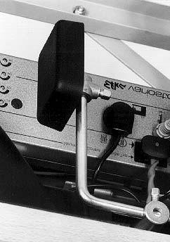
19 5.7 Sewing-foot stroke The height of the sewing-foot stroke is set with adjusting wheel 1. Machines without FA (without Thread Trimmer) On these machines the speed of rotation is not checked. Please comply with the note and table below. Machines with FA (with Thread Trimmer) The sewing-foot stroke and stitch rate are interdependent. A potentiometer is linked mechanically with the adjusting wheel 1. By means of this potentiometer the control unit detects which foot-stroke has been set and restricts the speed accordingly. Machines with HP 13-7 (Speedomat) The maximum stroke can be activated while sewing is in progress with the knee switch 2. Like machines with FA, these machines also have a potentiometer. Adjusting the sewing-foot stroke Set adjusting wheel 1. Min., A, B, C, D, E, F, max. min. = minimum stroke max. = maximum stroke NOTE In order to ensure maximum durability and safety in operation, the maximum stitch rates given in the table below should not be exceeded. GB Stitch-length range Adjusting Subclass Max. stitch rate mm wheel item stitches/min (mm foot stroke) 0-6 min. - B / (up to 2 mm) -VF-373 / VF AE-73 / AE FAS FAS all others (3 500) 1) C - D -VF-373 / VF (2-5 mm) -AE 73 / VF all others (3 000) 1) E - max all (5-7 mm) 6-9 min - max all (1-7 mm) 1) On machines with the speedomat HP 13-7 the stitch rate may be increased by about 300 stitches/min to the figures in brackets. The HP 13-7 is described in detail on page


20 5.8 Sewing-foot pressure The required sewing-foot pressure is set with rotary knob 1. to increase sewing-foot pressure = turn knob 1 clockwise to decrease sewing-foot pressure = turn knob 1 anti-clockwise. 5.9 Stitch length The required stitch length is set with rotary knob 2. to increase stitch length = turn knob 2 clockwise to decrease stitch length = turn knob 2 anti-clockwise nd Stitch length The following subclasses are equipped with the 2nd stitch length: 767-FAS-373-RAP-HP, 767-FAS-573-RAP-HP, 767-KFA-373-RAP-HP, 767-KFA-573-RAP-HP, 767-FAS-473-RAP-HP. Thus it is possible to activate the 2nd stitch length through one switch. Use the setting wheels 3 and 5 to set both stitch length. Set the longer stitch length with the upper setting wheel 3. Set the shorter stitch length with the lower setting wheel 5. Altering the shorter stitch length will be easier if the longer stitch length is activated (LED 7 on) beforehand. Attention! The stitch length adjusted at the lower setting wheel 5 must never be greater than that adjusted at the upper setting wheel 3. With the switch 4 you can change over from one stitch length to the other. When the LED 7 is on, the longer stitch length is active. When the LED 3 is off, the shorter stitch length is active. 18
 GB LED LED 5 = LED 6 = LED 7 = Display Sewing motor switched on Lock-stitches suppression switched on Stitch length Press and hold down key 1.")
21 6. Keys on sewing arm 5 6 (7) Key key 1 = key 2 = key 3 = key 4 = Function Intermediate lock-stitches during sewing Raises or lowers needle Suppress starting or finishing lock-stitches Stitch length (4) GB LED LED 5 = LED 6 = LED 7 = Display Sewing motor switched on Lock-stitches suppression switched on Stitch length Press and hold down key 1. Intermediate lock-stitches are sewn. The machine sews backwards for as long as the key is held down. Press key 2. The needle is raised or lowered. Press key 3. The next starting or finishing lock-stitches are not sewn. Press key 4. The 2nd stitch length is activated. If the 2nd stitch length has already been activated then pressing key 4 reactivates the 1st stitch length. 19
22 7. Control unit and operating panel IMPORTANT! This manual covers only those key functions and parameter changes available to the operator. For a more detailed description of the control unit please consult the motor manufacturer s current Operating manual (supplied). The operating panel is used to program the control unit and to set seam functions. Depending on the nature of the job, sewing may be executed manually or by seam programming. For various sewing tasks seams can be programmed for which the functions (starting and finishing lock-stitches, stitch counting etc.) and parameter values (number of stitches, seam length, speed of rotation etc.). Entry is carried out in programming mode. The parameters and the values assigned are displayed. The seam programs are not lost even if the sewing machine is switched off (battery buffer). In order to avoid the inadvertent alteration of pre-set functions operation is divided into several levels (operator, technician, fitter). The operator (seamstress) can program it directly. On the other levels access is contingent on the entry of a code number. RESET If the control unit is hopelessly misadjusted, this function allows the technician to reset all adjusted values to their default (ex-works) setting. This function is described in the Installation Instructions. 20
23 7.1 V810 Operating Panel Keys C D E F G A B Key Function Settings P Start or end programming mode E Confirm a parameter-value change + Increase a displayed parameter value - Decrease a displayed parameter value 1 Starting bar tack or starting stitch condensation SINGLE / DOUBLE / OFF 2 Ending bar tack or ending stitch condensation SINGLE / DOUBLE / OFF 3 Autofootliftonstopinmid-seam ON/OFF 3 Auto foot lift after thread trimming ON / OFF 4*** Basic needle position (UT/OT) POSITION 1 / POSITION 2 A* Key for bar tack suppression or activation B** Key for needle up/down or shift-key in programming mode GB Symbol C D E F Function Automatic rotation speed active Light barrier switched on Machine running Limited rotation speed active * Other functions possible (see parameter 293) ** Other functions possible (see parameters 294) *** Other functions possible (see parameters 291) e.g. A key parameter F B key parameter F
24 7.2 V820 Operating Panel Keys Key Function Settings P Start or end programming mode E Confirm a parameter-value change + Increase a displayed parameter value - Decrease a displayed parameter value 1 Starting bar tack or starting stitch condensation single / double / off 2 Seam stitch counting forward / reverse / off 3 Light barrier function bright-dark / dark-bright/ off 3 Auto foot lift after thread trimming on / off 4 Ending bartack single / double / off or ending stitch condensation 5 Thread cutter/thread wiper thread cutter/thread cutter and thread wiper / off 6 Auto foot lift on stop in mid-seam on / off Auto foot lift after thread trimming on / off 7 Basic needle position position 1 / position 2 8 Bobbin thread monitor on / off 9 Key function programmable 0 Teach in / sew stored sewing program 22
25 Symbol Functions A* Key for bar tack suppression or activation B** Key for needle up/down or shift-key in programming mode C Abbreviation C for the code number D Abbreviation F for the parameter number E Program number in teach-in mode F Seam-section number in teach-in mode G Cut-out active H Entry via keys disabled I Error message J Stitch-rate entry in teach-in mode K Bobbin-thread monitor on. Symbol flashes when the bobbin is running out L Speed limit effective M Right needle switched off O Machine running P Automatic speed effective Q Left needle switched off GB 23
26 7.3 Changing parameter values CAUTION! After changing parameters it is essential to carry out a sewing run. Only then is the altered setting properly saved. If sewing does not take place, the new setting is lost when the main switch is turned off. Parameters are changed and switched on and off with the P, E, + and - keyson the operating panel. The parameters which can be changed at operator level are listed below. 1. Switch on mains. 2. Start programming mode Press the P key. The last parameter to have been called appears. If no parameter has been called since the main switch was turned on, F appears in the display. 3. Select required parameter Press the + or - key repeatedly until the required parameter appears in the display. If the + or - key is held down, the parameter number automatically cycles until the key is released. Pressing the E key displays the parameter value. 4. Change displayed parameters Press the + or - keys to change the value of the parameter or switch its function on and off. 5. Save change parameter values Press the E key to change further parameter values. The changed parameter value is saved. The next operator-level parameter appears in the display. or: Press the P key to leave programming mode. The last parameter value to have been changed is saved. The control system leaves programming mode. Commencing sewing saves the new values, which are thus preserved when the machine is switched off. 7.4 Direct parameter number selection The parameter number can also be selected directly: When a parameter number is displayed, press the >> key. The first character flashes. Move to the next character by pressing the + or - keys. 24
27 7.5 Operator-level parameter list for EFKA controls DA82GA and 6F82FA Parameter Adj. Range Preset No. Abbr. Name/Function min max 100R 000 Arv starting-bar-tack stitches forward Arr starting-bar-tack stitches backward Err ending-bar-tack stitches backwards Erv ending-bar-tack stitches forwards LS number of light-barrier equalisation stitches (large stitch length) 005 LSF number of light-barrier filter stitches for knits 006 LSn number of seams terminated with the light barrier 007 Stc number of stitches in the automatically-produced seam section 008 F assigning a function to key = softstart ON/OFF 2 = ornamental-stitch bar tack ON/OFF 3 = stroke adjustment press and release = ON / press and hold = OFF 4 = needle cooling ON/OFF 5 = handwheel reverse ON/OFF ** 009 LS light barrier ON/OFF OFF ON OFF 010 cls number of light-barrier equalising stitches (small stitch length) 013 FA thread cutter ON/OFF OFF ON ON 014 FW thread retractor ON/OFF OFF ON ON 015 StS stitch count ON/OFF OFF ON ON 080 SAv number of stitches, starting decorative-stitch bar tack forwards 081 SAr number of stitches, starting decorative-stitch bar tack backwards 082 SEr number of stitches, ending decorative-stitch bar tack backwards 083 SEv number of stitches, ending decorative-stitch bar tack forwards 085 cfw residual-thread-monitor stitch count F-195 = F-195 = GB 25
28 8. Sewing This description is based on the following assumptions: The machine is a single-needle machine fitted with the following optional equipment: - FA Thread Trimmer - RAP Electro-pneumatic seam-locking and sewing-foot lift, pedal-operated - FLP Electro-pneumatic sewing-foot lift, pedal-operated - HP Electro-pneumatic rapid stroke adjustment The following functions are set at the operating panel: - starting or finishing lock-stitch : ON - sewing-foot position before and after cutting: DOWN - needle position before cutting: DOWN (1st position) - needle position after cutting: UP (turn-back after starting 2nd position) Main switch on. The last sewing process was completed with finishing lock-stitch and thread cutter. Operating and function sequence Sewing process (4) Operation / Explanation Prior to sewing Starting position Position material correctly for starting the seam. - Pedal in rest position The machine is at a halt. Needle up, sewing feet down. - Press key 2. The needle is fully lowered. - Push pedal half-way back. The sewing feet are raised. - Push material forward until it touches the needle. Continued on next page! 26
 Sew an intermediate lock-stitch - Push pedal forwards and hold it there. The starting lock-stitch is sewn.")
29 Sewing process Operation/explanation (4) At start of seam Sew starting lock-stitch and continue Sew only starting lock-stitch Do not sew starting lock-stitch In mid-seam Interrupt the sewing process Sew a corner Resume the sewing process (after releasing the pedal) Sew an intermediate lock-stitch - Push pedal forwards and hold it there. The starting lock-stitch is sewn. Sewing then continues at the speed of rotation determined by the pedal. - Push pedal forwards briefly. The machine halts in the 1st position after the starting lock-stitch. - Press key 3, then push pedal forwards. The machine begins sewing at the speed of rotation determined by the pedal. - Release pedal (rest position). The machine halts in the 1st position. The sewing feet are down. - Pull pedal half-way back. The machine halts in the 1st position. The sewing feet are up. - Rotate the material about the needle. - Push pedal forwards. The machine sews at the speed of rotation set by the pedal (no starting lock-stitch is sewn). - Press key 1 and continue to hold the pedal forwards. The machine sews backwards for as long as key 1 is held down. The speed of rotation is determined by the pedal. GB Continued on next page! 27
30 Sewing process Transfer-seam over-sewing Operation / Explanation - Operate knee switch. The speed of rotation is restricted to stitches/min. At the end of the seam Remove material - Pull pedal fully back and hold it there. The finishing lock-stitch is sewn. The thread is cut off. The machine halts in the 2nd position. The needle is up (turn-back ). The sewing feet are up. Do not raise sewing feet Do not sew a finishing lock-stitch - Briefly pull pedal fully back. The finishing lock-stitch is sewn. The thread is cut off. The machine halts in the 2nd position. The needle is up (turn-back). The sewing feet are down. - Pres key 3 and pull pedal fully back. The finishing lock-stitch is not sewn. The thread is cut off. The machine halts in the 2nd position. The needle is up (turn-back). The sewing feet are up or down depending on the pedal position. 28

. Maintenance intervals may need to be shorter when processing heavy-shedding materials. 9.")
31 9. Maintenance Caution! Danger of injury! Turn off main switch! Maintenance may only be carried out with the sewing machine switched off. Maintenance work must be carried out no less frequently than at the intervals given in the tables (see operating hours column). Maintenance intervals may need to be shorter when processing heavy-shedding materials. 9.1 Cleaning and inspection A clean sewing machine is a protection against malfunctions. 1 2 GB
32 Maintenance work Explanation Operating to be carried out hours Upper part of machine - Remove lint, pieces of thread and other cutting waste. - Clean oil collector. Places in special need of cleaning: - area under the needle plate 1 - feeders - area around the shuttle 2 - upper part of bobbin housing 3 - inner surface of shuttle cover - needle-thread tensioners - Remove lint and oil spills with a cloth 8 8 Sewing drive - Check the condition and tension of the V-belt. It must be possible to depress the V-belt by about 10 mm by pressing it with a finger at its mid-point. 160 Compressed-air maintenance unit (optional equipment) - Check the water level in the pressure regulator. Clean the filter insert. The water level must not rise as high as the filter insert 4. - After screwing in the drain screw 6 blast water under pressure out of the water separator 5. NB: The water separator 5 is fitted with semi-automatic condensation drainage. When the pressure falls below a certain level the condensation is automatically drained. Dirt and condensation are separated out by the filter insert 4. - Disconnect the machine from the compressed-air supply. - Screw in drain screw 6. Theremustbenopressureinthe machine s pneumatic system. - Unscrew water separator 5. - Unscrew filter insert 4 Wash the filter shell and insert with cleaning fluid (not solvent!) and blast clean. - Re-assemble and connect the maintenance unit


33 9.2 Lubrication (until July 2003) (from August 2003) Check the oil level at the sight glass 2 every week. Top up the oil reservoir only with DA-10 oil or an equivalent oil with the following specification: Viscosity at 40 C : 10 mm 2 /s Ignition point: 150 C GB DA-10 can be obtained from DÜRKOPP ADLER AG sales outlets. The part numbers are: 250 ml - Container: litre - Container: litre - Container: litre - Container: Remove oil-filling screw 1 and pour in oil. Check oil level at sight glass 2. The oil level must be between EMPTY and FULL. Replace oil-filling screw 1. Clean up any oil overflow. 31

34 10. Optional equipment 10.1 Residual-thread monitor RFW 13-3/RFW 13-6/RFW 13-8/RFW The residual-thread monitor monitors the amount of thread in the shuttle bobbin. An acoustic signal is sounded when only a small amount of thread is left. The operative can finish the seam and fit a new spool. This avoids material damage and thus any need for repairs. The residual-thread monitor RFW 13-3, part no.: , can be fitted to all single-needle 767 sewing machines with a thread cutter. The residual-thread monitor RFW 13-6, part no.: , can be fitted to the class 767-KFA-573-RAP/HP (short thread trimmer). The residual-thread monitor RFW 13-8, part no.: , can be fitted to the class 767-KFA-373 (short thread trimmer). The residual-thread monitor RFW 13-9, part no.: , can be fitted to the class 767-FAS-473 / 767-VF-573 (oversized hook). Function and operation of the residual-thread monitor If the light beam from the light barrier is reflected by the surface 3 of the spool, the sewing process is interrupted. An acoustic signal sounds for 2 seconds. Release the pedal and then push it forwards again. The seam is continued. The amount of thread in the supply groove 4 of the shuttle bobbin is usually sufficient to complete it. At the end of the seam pull the pedal back. The thread is cut off. The acoustic signal sounds for a further 2 seconds to remind the operator to change the spools. 32


35 Caution! Danger of injury! Turn off main switch! The shuttle bobbin must not be changed unless the machine is switched off. Change the bobbin. A new seam can now be sewn. IMPORTANT! The bobbin must be put in place with the groove 2 facing downwards. The area of the spool housing and the light barrier must be kept free of dust. If the empty bobbin is not replaced by a full one, the acoustic signal sounds again when the next seam is sewn. Depending on the setting: - Either the signal sounds continuously all the time the seam is being sewn until the thread is cut - or it sounds for 2 seconds the next time the thread is cut. Winding on spool thread. The procedure is described in this operating manual. IMPORTANT! The groove 2 must face upwards for winding on. Wind the thread round the spool manually only in the area of the supply groove 4. GB

36 10.2 2nd stitch length STLS The facility to activate a 2nd stitch length makes it possible to switch rapidly from the assembly seam to the subsequent overstep seam. The 1st or 2nd stitch length is selected with the keys on the sewing arm. The 2nd stitch length is always smaller than the 1st. The 2nd stitch length is active when the machine is switched on. Function and operation Name Function 1 Rotary knob Adjusts 1st stitch length 2 Scale 2nd stitch length is displayed 3 Knurled screw Adjusts 2nd stitch length 4 Scale 1st stitch length is displayed 34


37 Integrated second stitch length The subclasses 767-FAS-373-RAP-HP, 767-FAS-573-RAP-HP, 767-KFA-373-RAP-HP, 767-KFA-573-RAP-HP, 767-FAS-473-RAP-HP are equipped with a second stitch length. Herewith it is possible to activate a shorter second stitch length just via a switch Both stitch lengths are defined by means of the two setting wheels 1 and 2. Set the longer stitch length with the upper setting wheel. Set the shorter stitch length with the lower setting wheel. With the switch 4 you can change over from one stitch length to the other. When the light emitting diode 3 is shining, the longer stitch length is active. When the light emitting diode 3 does not shine, the shorter stitch length is active. GB ATTENTION! The stitch length adjusted at the lower setting wheel must never be longer than that adjusted at the upper setting wheel. 35


38 10.3 Electro-pneumatic rapid stroke adjustment HP The sewing-foot stroke and stitch rate are interdependent. A potentiometer is linked mechanically with the adjusting wheel. By means of this potentiometer the control unit detects what foot-stroke has been set and restricts the speed of rotation accordingly. The values are given in the table on page 17. Themaximumstrokecanbeactivatedwhilesewingisinprogresswiththekneeswitch2. Caution! Danger of injury! Turn off main switch! Adjust the sewing-foot stroke only with the machine switched off. Operation mode of the quick stroke adjustment The activation period of the maximum sewing foot stroke depends on the set operation mode. It is possible to choose between three operation modes. The individual operation modes are determined by the adjustment of the parameters F-138 and F-184 at the control panel (see enclosed instructions of the motor manufacturer). Operation mode Keystroke mode F-138 = off F-184 = 0 Operation / Explanation The maximum sewing foot stroke remains engaged as long as the knee switch 2 is actuated. Push-lock mode F-138 = on Keystroke mode with min. speed F-138 = off F-184 > 0 The maximum sewing foot stroke is engaged by actuating the knee switch 2. By actuating the knee switch once again the maximum sewing foot stroke is disengaged. The maximum sewing foot stroke remains engaged as long as knee switch 2 is actuated. After releasing the knee switch the machine sews with maximum sewing foot stroke until the set minimum speed is reached (parameter F-184). Then the seam is continued with normal sewing foot stroke. 36

39 10.4 Upper and lower conveyor rollers SP The removal of the material by the upper and lower conveyor rollers after sewing ensures a smooth and uniform product. The speed with which the material is removed can be exactly matched to the stitch length. The pressure can be set at a level appropriate to the material. GB Lever 1 Matches the speed of the upper and lower conveyor rollers to the stitch length set. Screw 2 Adjusts the upper conveyor-roller pressure to the material being processed. Lever 3 Lowers the upper conveyor roller. 37
40 10.5 Automatic lowering WTA 13-2 This is an optional item to go with the upper and lower conveyor rollers. It enables the stitches to be adjusted from the beginning of the seam to the automatic lowering of the upper roller. This ensures that the roller is not lowered until the material is beneath it. Manual operation Parameter Function F-186 = 0 Lowering or lifting the feed roller through actuating the button. Automatic operation Parameter Function F-186 > 0 Automatic lowering of the roller after a number of stitches have been set F-260 = ON or OFF Stitch delay after sewing foot lowering until roller lowering in the seam OFF = Stitch delay Off ON = Stitch delay On F-261= 0 Lift roller, but without sewing foot lift and backtack F-261 = 1 Lift roller with sewing foot lift and backtack F-261 Lift roller only with sewing foot lift F-261 Lift roller only with backtack F-262 Roller remains lowered when switching on high lift for walking foot F-262 = 1 Roller is lifted, when switching on high lift for walking foot 38
. Prerequisite is the sewing drive DC160")
41 10.6 Additional tension Additional tension FS 13-1 The classes 767-FAS-373-RAP-HP, 767-FAS-573-RAP-HP, 767-KFA-373-RAP-HP, 767-KFA-573-RAP-HP can be equipped with a pneumatic additional tension FS 13-1 (for 2 needle machines with pneumatic additional tension - on request). Prerequisite is the sewing drive DC1600 / DA82GA Operation If required, the pneumatic additional tension can be engaged or disengaged at any time. The additional tension is activated by key 5. When the LED 1 is shining, the additional tension is active. For this purpose the parameter F-147 has to be set to 1". GB Function of the main thread tension and the additional thread tension depending on the sewing foot lift (NFL) Sewing foot lift (NFL) Sewing foot lift (NFL) in the seam after thread trimming Parameter Main Add. Main Add. setting thread tension thread tension thread tension thread tension F-196 = F-196 = F-196 = F-196 = = thread tension mechanically opened 0 = thread tension mechanically closed If the additional thread tension is open, it remains open when the sewing foot is lifted. When the machine is switched off, the previously set status of the additional thread tension is maintained via the net. 39
42 Function of the additional thread tension depending on the stroke adjustment (HP) and the Speedomat Parameter Stroke adjustment (HP) max. Stroke adjustment by setting adjustment via knee switch wheel when the HP-speed of parameter F-117 is reached (Speedomat) F-197 = F-197 = F-197 = 2 0 (*) 1 F-197 = (*) When the max. stroke adjustment (HP) is switched on via knee switch and the HP-speed of parameter F-117 is reached by the Speedomat, the additional thread tension is switched on automatically. 1 = Additional thread tension is engaged (= mechanically closed) 0 = Additional thread tension is not engaged (= mechanically opened) If the additional thread tension is closed, it remains closed during the stroke adjustment. When the machine is switched off, the previously set status of the additional thread tension is maintained via the net. Basic adjustment in the control box for the automatic stepwise speed reduction (Speedomat) by the setting wheel for the height of the alternating feeding stroke Parameter 188 Step Whole Speedomat range Step Maximum speed allowed, parameter F-111 = min -1 Step Linear stepwise lowering of the maximum speed (Speedomat) Step Maximum speed allowed, parameter F-117 = min -1 40


43 10.7 Seam center guide (only if 767-E74/... existing) General In order to operate the seam center guide the sewing drive DC1600/DA82GA is required. The seam center guide serves as guiding aid for topstitching operations. It guides the center of two parallel seams to ensure an equal distance to the left and the right needle. Support pressure of the stop guide for the seam center guide ATTENTION! The maximal pressure for the seam center guide should not exceed 3 bar! To set the support pressure pull out the turning handle of the pressure regulating valve of the seam center guide and twist it. Turning in clockwise direction= to increase the bearing pressure Turning in counter-clockwise = to reduce the bearing pressure GB N E... on request 41
44 Working method and parameter adjustment of the seam center guide (in conjunction with sewing drive DC1600/DA82GA only) When the machine is switched off, the seam center guide is down (= on). Immediately after the machine has been switched on the seam center guide is always up (= off). The seam center guide can be switched on and off at any time by means of key 5 (see operating instructions) of the 5-key-panel at the machine. Possible parameter adjustments of the seam center guide: Parameter Value Function of the seam center guide F on and off by means of key 5 of the 5-key-panel only F-186 > 0... automatically on after stitch counting F in case of bartacking and sewing foot lifting always on, if it is switched on F off only during bartacking and sewing foot lifting, if it has been switched on before F off only during sewing foot lifting, if it has been switched on before F off only during bartacking, if it has been switched on before F in case of stroke adjustment (HP) by knee switch always on, if it is switched on F off during stroke adjustment (HP) by knee switch, if it has been switched on before If the seam center guide is off (up), the status remains unchanged, irrespective of how the parameters F-261 and F-262 are adjusted and which function is active. 42
45 10.8 Skip Stitch Device (SSD) FSE 13-1/2 Sewing Mode In case of a skipped stitch during normal sewing, the motor stops and the LED shines. The release of the motor can be done by the touch-key only. Bobbin Mode For bobbin winding, the SSD has to be switched on into the bobbin mode. Hold the touch-key for 5 seconds onto the SSD. GB After 5 seconds, the LED starts flashing indicating that the thread monitor is disabled. Now you can start to wind a bobbin. By activating the foot pedal for thread trimming the thread monitor is enabled again. 43
46 Service Mode For mechanical adjustments, the SSD has to be switched into the service mode. In this mode the thread monitor will be disabled. Following steps are necessary to come into this mode. Switch off the machine (it should be off for longer than 2 sec.) Hold the touch-key onto the SSD and Switch on the machine again The LED flashes, indicating that the thread monitor is disabled. The machine stays in the service mode until it is switched off again. 44
 Position 2A (trailing edge 034\") Parameter 180 Number of reversion increments 114 Parameter 181")
47 11. Short thread trimmer (KFA) 11.1 Check EPROM-Version It is necessary to have at least the EPROM-Version 3312 F. You can check the EPROM-Version with Parameter 179. Parameter Settings Parameter 136 to 2 Parameter 154 to 7 Parameter 171 Position 2 (leading edge 496") Position 2A (trailing edge 034") Parameter 180 Number of reversion increments 114 Parameter 181 Activation delay of reversion 10 Parameter 182 Reversion ON Parameter 190 Activation angle of the thread trimmer 300 Parameter 192 Activation angle of thread tension release Position of the thread-pulling knife and the counter-knife See Service Instructions Class Adjust the thread cutting stitch before thread cutting In order to get a short trimming, it is necessary that the machine executes a short stitch right before cutting (approx mm). The length of the last stitch before thread cutting can be adjusted. Thus, the lengths of the cut-off needle and bobbin threads can be influenced. Both thread ends should have almost the same length. GB The length of the thread cutting stitch is influenced by means of screw 1. Turningthescrew 1inclockwisedirection means longer stitches. Turning the screw 1 counter-clockwise means shorter stitches. 1 45
Spezialnähmaschine. Betriebsanleitung. Instruction manual. Instructions d emploi
 867 Spezialnähmaschine Betriebsanleitung Instruction manual Instructions d emploi D GB F Postfach 17 03 51, D-33703 Bielefeld Potsdamer Straße 190, D-33719 Bielefeld Telefon +49 (0) 521 / 9 25-00 Telefax
Spezialnähmaschine. Betriebsanleitung. Instruction manual. Instructions d emploi
 867 Spezialnähmaschine Betriebsanleitung Instruction manual Instructions d emploi D GB F Postfach 17 03 51, D-33703 Bielefeld Potsdamer Straße 190, D-33719 Bielefeld Telefon +49 (0) 521 / 9 25-00 Telefax
Part 1: Operating Instructions Cl. 271 to 274
 Contents Page: Preface and General Safety Notes Part 1: Operating Instructions Cl. 271 to 274 1. Product Description 1.1 Short Description and Proper Use..................... 5 1.2 Technical Data................................
Part 1: Operating Instructions Cl
 Contents Page: Preface and General Safety Information Part 1: Operating Instructions Cl. 381-382 1. Product Description........................... 5 2. Proper Use................................. 5 3.
CNC Knopfannähautomat CNC Automat for Button Sewing
 50 CNC Knopfannähautomat CNC Automat for Button Sewing Bedienanleitung / Operating Instructions Aufstellanleitung / Installation Instructions Serviceanleitung / Service Instructions 1 2 Postfach 17 0 51,
Manual, complete. Downloaded from manuals search engine
 Manual, complete 580 Double-chainstitch buttonhole automat Single-chainstitch automat for stitched eyelets Operating Instructions Installation Instructions Service Instructions! Postfach 17 0 51, D-70
Operation Manual GF MH/L38 GF MH/L38 GF MH/L38 GF MH/L38
 Operation Manual GF-137-443 MH/L38 GF-137-448 MH/L38 GF-237-443 MH/L38 GF-237-448 MH/L38 ANITA B, s.r.o. Průmyslová 2453/7 680 01 Boskovice Czech Republic tel: +420 516 454 774 fax: +420 516 452 751 e-mail:
Double-chainstitch buttonhole automat. Single-chainstitch automat for stitched eyelets
 Manual, complete 580 Double-chainstitch buttonhole automat Single-chainstitch automat for stitched eyelets Operating Instructions Installation Instructions Service Instructions 2 3 Postfach 7 03 5, D-33703
CONTENTS PRECAUTIONS BEFORE STARTING OPERATION PREPARATION FOR OPERATION CAUTIONS ON USE OPERATION
 CONTENTS PRECAUTIONS BEFORE STARTING OPERATION ------------------------------------- 1 PREPARATION FOR OPERATION 1. Adjustment of needle bar stop position ---------------------------------------------------------
FBX-PA-2AC. Third edition : April No
 FBX-PA-2AC Third edition : April 2006 No. 060058 INTRODUCTION Thank you very much for purchasing Kansai Special FBX series. Read and study this Instruction Manual carefully before you start any of the
581 Service Instructions
 581 Service Instructions IMPORTANT READ CAREFULLY BEFORE USE KEEP FOR FUTURE REFERENCE All rights reserved. Property of Dürkopp Adler AG and protected by copyright. Any reuse of these contents, including
First published : May 1997 Fourth edition : January No
 First published : May 1997 Fourth edition : January 2006 No. 050153 INTRODUCTION Thank you for your purchasing Kansai Special's FX Series. Read and study this instruction manual carefully before beginning
Revolutionary / 96
 Industrial 2595/96 Revolutionary... The combination of revolutionary design and innovative engineering has led to the development of something quite special, extraordinary something, which will influence
Intro to the Sewing Machine
 Intro to the Sewing Machine 1. Bobbin Cover Opens to allow you to put the bobbin and bobbin case in the machine. 2. Stitch Plate Where the seam allowance guidelines are found. Each line is 1/8 apart, beginning
DAC basic/classic Instructions for use. Software version: B03.0 or later
 DAC basic/classic Instructions for use Software version: B03.0 or later IMPORTANT READ CAREFULLY BEFORE USE KEEP FOR FUTURE REFERENCE All rights reserved. Property of Dürkopp Adler AG and protected by
PFAFF. rom the library of: Superior Sewing Machine & Supply LLC. Service Manual Justieranl. engi. 7.92
 PFAFF 5642 Service Manual 296-12-13925 Justieranl. engi. 7.92 Notes on safety The machine must only be commissioned in full knowledge of the instruction book and operated by persons with appropriate training.
FBX1104P FBX1104 FBX1106P FBX1106
 FBX1104P FBX1104 FBX1106P FBX1106 Second edition : September 2004 No. 040037 INTRODUCTION Thank you for your purchasing Kansai Special's FBX Series. Read and study this instruction manual carefully before
WX8800 WX8700 LX5801 WX8842 WX MC30
 WX8800 WX8700 LX5801 WX8842 WX8842-1 MC30 First published : August 1991 Third edition : August 2004 No. 040037 INTRODUCTION Thank you for your purchasing Kansai Special's WX Series. Read and study this
UK10 UK11. First published: June No.KX03023
 UK10 UK11 First published: June 2003 No.KX03023 INTRODUCTION Thank you for purchasing Kansai Special s UK series machine. Please study this instruction manual carefully before operating the machine. 1.
Instruction manual. Printed: Czech Republic
 Instruction manual 525 Minerva Boskovice, a.s., Sokolská 60, CZ - 680 17 Boskovice Tel.: +420-516-453434, 453433, 494111 Fax: +420-516-452165 http://www.minerva-boskovice.com Edition : 01/2004 Printed:
SERVICE MANUAL PARTS LIST MODEL: NH40
 SERVICE MANUAL & PARTS LIST MODEL: NH40 CONTENTS What to do when... 1-3 SERVICE ACCESS Face Cover... 4 Bed Cover... 5 Free-arm Cover... 6 Front Cover... 7 Rear Cover... 8 MECHANICAL ADJUSTMENT Presser
SERVICE MANUAL AND PARTSLIST
 SERVICE MANUAL AND PARTSLIST Next 20 CONTENTS WHAT TO DO WHEN... 1~3 SERVICE ACCESS FACE COVER... 4 TOP COVER... 4 BASE COVER... 5 REAR COVER... 6 FRONT COVER... 7 MECHANICAL ADJUSTMENT NEEDLE THREAD TENSION...
SERVICE MANUAL MODEL: 13512, 14412, 15312
 SERVICE MANUAL MODEL: 13512, 14412, 15312 CONTENTS TROUBLESHOOTING... 1-3 SERVICE ACCESS (1) FACE COVER, BELT COVER... 4 SERVICE ACCESS (2) BASE PLATE... 5 SERVICE ACCESS (3) FRONT COVER... 6 SERVICE ACCESS
NAMES OF PARTS. 1 Thread guide for bobbin winding 2 Take-up lever. 3 Upper thread tension dial. 4 Face cover. 5 Thread guide for upper threading
 6 Presser foot thumb screw 9 Spool pins (retractable) 8 Shuttle cover 5 Thread guide for upper threading 7 Presser foot 4 Face cover NAMES OF PARTS.r4r : VjN S* ;WWE7-17 16 15 MODEL 860.-.-.- --. :.---.-
the single-needle high-speed seamer, POWERLINE 2235, with triple feed (bottom, needle and alternating top feed) and horizontal hook
 and horizontal hook") Industrial 02 // 03 Philosophy Philosophy The fine tension of the surface signalizes power and dynamics, the design combines traditional forms with ergonomic elegance. During the development of the single-needle
Industrial 02 // 03 Philosophy Philosophy The fine tension of the surface signalizes power and dynamics, the design combines traditional forms with ergonomic elegance. During the development of the single-needle
Parts List and Sewing Equipment Please enter your Chinese text here!
 Parts List and Sewing Equipment Please enter your Chinese text here! 281 Manufacturer: Contact: Manufacturer: Contact: Dürkopp Adler Manufacturing (Shanghai) Co., Ltd. 1201 Luoshan Road, Pudong New Area,
SERVICING MANUAL 419S/423S
 SERVICING MANUAL 415 419S/423S TROUBLESHOOTING PROBLEM CAUSE REMEDY REFERENCE 1. SKIPPING 1. NEEDLE IS NOT INSERTED INSERT THE NEEDLE PROPERLY. STITCHES PROPERLY. 2. NEEDLE IS BENT OR WORN. CHANGE THE
S-85SCH
 4411-4423-4432-4443-4452 5511-5523-5532-5554 44S-85SCH Service Manual 104 73 14-26 2014-02-24 CONTENTS 1. Names of principal parts...2 2. Removing methods of external parts 2-1 Sewing table...3 2-2 Face
the needle, the user must take sufficient care to avoid injury and observe the sewing area continuously while sewing.
 / - nstruct0fl maflua 7 the needle, the user must take the light bulb is 15 watts. agent. by anyone but an authorized Pfaff D) The drive belt must never be adjusted B) When leaving the machine, chan C)
SEWING MACHINE For use with Janome HD 1000
 SEWING MACHINE For use with Janome HD 1000 YALE CENTER FOR ENGINEERING INNOVATION AND DESIGN Table of Contents p. 3-5... Winding the Bobbin p. 6-7... Threading the Bobbin p. 8-10... Threading the Needle
887 Service Instructions
 887 Service Instructions All rights reserved. Property of Dürkopp Adler AG and copyrighted. Reproduction or publication of the content in any manner, even in extracts, without prior written permission
Top Innovations, Inc. Innovative Products to Make Your Life Easier. Model SP-402 Owner s Manual
 Top Innovations, Inc. Innovative Products to Make Your Life Easier Model SP-402 Owner s Manual THIS IS NOT A TOY! Adult supervision recommended Item contains sharp functional points and small parts Machine
Symbols used. Move the part in the direction of the arrow. Set the clearance as indicated. Move the part to its highest or lowest position.
 4.1999. This service manual was compiled for use when repairing the XL5300, 5200, 5100, 5030, 5020, 5010,PX300,200,100 Zigzag Stitch Sewing Machines. Use this manual, together with the Parts Catalog, when
Part 3: Service Instructions Cl
 Contents Page: Part 3: Service Instructions Cl. 550--. General................................................. 3. Setting the Machine Head...................................... 4. Arm Shaft Crank............................................
INSTRUCTION. Industrial Sewing Machines V7100/D,DE,F,ML W8100/D,DE,F,C W8042 W V7002-1S W8103-1S. No Third edition : March 2001
 INSTRUCTION Industrial Sewing Machines V7100/D,DE,F,ML W8100/D,DE,F,C W8042 W8042-1 V7002-1S W8103-1S Third edition : March 2001 No. 010012 INTRODUCTION Thank you for your purchasing Kansai Special's V.W
SERVICE MANUAL FOR HOMELOCK M1034D 2034D 1134DW 1134D
 SERVICE MANUAL FOR HOMELOCK M1034D 2034D 1134DW 1134D 11.2000 2.2012 I HOW TO USE THIS MANUAL... 1 II HOW TO ADJUST... 2 1. Height of needle bar... 2 2. Position of the lowerlooper... 3 3. Timing of the
SINGER 591D200A 591D240A 591D303A 591D305A 591C308A. rom the library of: Superior Sewing Machine & Supply LLC 591D300A
 SINGER 591D200A 591D240A 591D300A 591D303A 591D305A 591D308A 591C200A 591C240A 591C300A 591C308A CONTENTS Page Introducingtlie NewSINGER* Sewing Machine Model 591 \ Oiling the Machine 2 Oiling the Puller
Out-Of-The-Box Basics: ID the Main Parts of a Sewing Machine
 Published on Sew4Home Out-Of-The-Box Basics: ID the Main Parts of a Sewing Machine Editor: Liz Johnson Tuesday, 27 September 2016 1:00 Sewing is an art. But it does rely on science and technology as well.
CAUTION- SAVE THESE INSTRUCTIONS This product is for household use, or equivalent.
 Never operate this sewing machine if it has a damaged cord or plug, if it is not working properly, if it has been dropped or damaged, dropped into water. Return this sewing machine to the nearest authorized
INSTRUCTION BX1425P,PSM,PTV BX1433P,PSM,PTV BX1025P,PSM BX1033P,PSM. No First published : November 1997
 INSTRUCTION Industrial Sewing Machines BX1425P,PSM,PTV BX1433P,PSM,PTV BX1025P,PSM BX1033P,PSM First published : November 1997 No. 970112 INTRODUCTION Thank you for your purchasing Kansai Special's BX
Instruction manual. Printed: Czech Republic
 Instruction manual 524 Minerva Boskovice, a.s., Sokolská 60, CZ - 680 17 Boskovice Tel.: +420-516-453434, 453433, 494111 Fax: +420-516-452165 http://www.minerva-boskovice.com Edition : 01/2004 Printed:
M PREMIUM. Additional Instructions. Neat seam beginning (NSB)
") 867 867-M PREMIUM Additional Instructions Neat seam beginning (NSB) IMPORTANT READ CAREFULLY BEFORE USE KEEP FOR FUTURE REFERENCE All rights reserved. Property of Dürkopp Adler AG and protected by copyright.
867 867-M PREMIUM Additional Instructions Neat seam beginning (NSB) IMPORTANT READ CAREFULLY BEFORE USE KEEP FOR FUTURE REFERENCE All rights reserved. Property of Dürkopp Adler AG and protected by copyright.
TORO 4000 TORO and. INSTRUCTION and SPARE PARTS MANUAL. artisanu. TORO 3000 and TORO Threading Diagram
 Please make sure that the thread is inserted between the two thread tension disks. If your brand of Thread pops-out of the tension disks, wind the thread all the way around the disks and back through the
Industrial 3721/3741/3745. Documented Quality - Stitch by Stitch
 Industrial 3721/3741/3745 Documented Quality - Stitch by Stitch Documented quality The POWERLINE 3721, 3741 and 3745 are quality assurance systems designed for use on safety relevant seams. The PFAFF docu-sewing
PicoDrive P45 PD2-L EcoDrive P74 ED-L
 Industrial PicoDrive P45 PD2-L EcoDrive P74 ED-L INSTRUCTION MANUAL This Instruction Manual is valid for drives from the following software version on: P45 PD2-L # 4_045_05 P74 ED-L # 1_074_08 296-12-19
HAPPY HCS Voyager: Level-1 Maintenance & Repair Intermediate-level repair / maintenance procedures
 TEXMAC Inc. HAPPY HCS Voyager Introduction Training page 1 HAPPY HCS Voyager: Level-1 Maintenance & Repair Intermediate-level repair / maintenance procedures Table of Contents Oiling/Cleaning Page 2 Removing
OPERATING INSTRUCTIONS 3421UX VETERANS BLVD, CARLSTADT, NJ 07072
 OPERATING INSTRUCTIONS 3421UX5-1 400 VETERANS BLVD, CARLSTADT, NJ 07072 CONTENTS DESCRIPTION... 3 OPERATOR INFORMATION... 5-8 INSTALLATION...... 4 ADJUSTMENT... 8-17 LUBRICATION... 5 INDEX Description
MF-7524 INSTRUCTION MANUAL
 MF-7524 INSTRUCTION MANUAL 1 CONTENTS Ⅰ. SPECIFICATIONS...1 Ⅱ. CONFIGURATION OF THE MACHINE COMPONENTS...2 Ⅲ. INSTALLATION... 3 1. Installing the machine head onto the table...3 2. Selecting the motor
888 Service Instructions
 888 Service Instructions All rights reserved. Property of Dürkopp Adler AG and copyrighted. Reproduction or publication of the content in any manner, even in extracts, without prior written permission
// 03 Philosophy
 Industrial 02 // 03 Philosophy Philosophy The POWERLINE is a high-speed seamer featuring bottom feed and needle feed another solution from the POWERLINE-model kit. This PFAFF INDUSTRIAL product closes
Computer-controlled, High-speed, Lockstitch Buttonholing Machine LBH-1790 LBH-1790S
 Computer-controlled, High-speed, Lockstitch Buttonholing Machine LBH-1790 LBH-1790S LBH-1790 The machine offers increased flexibility. It achieves the highest productivity and seam quality. The machine
Service Manual 1st Release August 2001
 Service Manual 1st Release August 2001 Contents 1 Foreword 3 Notes on the sewing machine in relation to environment, handling, cleaning and safety 5 Specifications off PFAFF machines 6 Removing the housing
MAIN PARTS
 MAIN PARTS 7 8 9 10 11 12 13 1 2 3 17 4 5 6 01 02 03 04 05 12 23 34 45 56 13 24 35 46 57 14 25 36 47 58 15 16 26 27 37 38 48 49 59 60 06 07 08 09 10 17 18 28 29 39 40 50 51 61 62 19 30 41 52 63 20 21 31
 Lockstitch machine with automatic thread trimmer J-150QVP INSTRUCTION MANUAL EN IMPORTANT: Read all safety regulations carefully and understand them before using your sewing machine. Retain this instruction
FLEXRISE2 VERSION. 2 LEG / 2 MOTOR ELECTRIC TABLE BASE (36 to 72 ) **PATENT PENDING**
 **PATENT PENDING**") FLEXRISE2 2 LEG / 2 MOTOR ELECTRIC TABLE BASE (36 to 72 ) VERSION A INSTRUCTION MANUAL CONTENTS: FLEX-MU-2L3S-C3672-K4# FEET-ADJ-UNV-2430# **PATENT PENDING** MAX Load 265 lbs (120 KG) Equally Divided MAX
FLEXRISE2 2 LEG / 2 MOTOR ELECTRIC TABLE BASE (36 to 72 ) VERSION A INSTRUCTION MANUAL CONTENTS: FLEX-MU-2L3S-C3672-K4# FEET-ADJ-UNV-2430# **PATENT PENDING** MAX Load 265 lbs (120 KG) Equally Divided MAX
SPIDA SAW OPERATIONS MANUAL
 SPIDA SAW OPERATIONS MANUAL CM SERIAL NUMBER. OCTOBER 2000 CONTENTS Page description 1.) Contents 2.) Safety First 3.) CM Overview 4.) CM Specifications 5.) CM Installation 6.) CM Operation Setting the
Quantum L Built-in Stitch Patterns. Large Back-Lit LCD Screen with Brightness Control
 Quantum L-500 Feature 401 Built-in Stitch Patterns Fulfill your creative dreams with a large selection stitches including basic, decorative and stretch stitches for clothing construction, quilting, home
CONTROL DA82GA3316 LIST OF PARAMETERS CONNECTION DIAGRAM TIMING DIAGRAMS. with control panel V810/V820
 CONTROL DA82GA336 with control panel V8/V82 LIST OF PARAMETERS CONNECTION DIAGRAM TIMING DIAGRAMS No. 4236 English FRANKL & KIRCHNER EFKA OF AMERICA INC. EFKA ELECTRONIC MOTORS GMBH & CO KG SINGAPORE PTE.
CONTENTS: 1. General safety instructions Introduction... 1
 CONTENTS:. General safety instructions.... Introduction.... Head of the sewing machine.... Hook and hook box..... Description.. Height setting of the hook.. Setting the distance of the hook from the needle..
С 800 CASSIDA C 800 HIGH SPEED COIN COUNTER
 С 800 CASSIDA C 800 HIGH SPEED COIN COUNTER This manual contains important information on safety measures and operational features. Please read it carefully before operating your coin counter, and keep
CONTENTS LOCATE AND IDENTIFY THE PARTS... WIND THE BOBBIN... PREPARE YOUR TOP THREAD... STITCH SELECTOR / STITCH LENGTH/STITCH WIDTH CONTROLS...
 SERVICE MANUAL SEWING MACHINE MODEL 385. 15208400 OCTOBER, 2003 CONTENTS LOCATE AND IDENTIFY THE PARTS... WIND THE BOBBIN... PREPARE YOUR TOP THREAD... STITCH SELECTOR / STITCH LENGTH/STITCH WIDTH CONTROLS...
Daily Maintenance. 2. Insert bobbin cases in to rotary hooks. Make sure bobbin thread is not over 2 inches long. Close bobbin case covers.
 Rotary hook 1. Open bobbin case covers and remove bobbin cases. Use brush to remove lint build up in and around rotary hooks. Compressed air may also be used. Daily Maintenance Cle aning Oiling Rotary
DU INSTRUCTION MANUAL
 DU-1281-7 INSTRUCTION MNUL CONTENTS 1. SPECIFICTIONS... 1 2. PREPRTION EFORE OPERTION... 2 2-1. Installing the knee lifter... 2 2-2. Installing the waste oil receiver... 2 2-3. Lubrication... 3 2-4. Oiling
pô1e -/C INSTRUCTION MANUAL FOR SEWING MACHINE WHITE
 pô1e -/C -- INSTRUCTION MANUAL I FOR SEWING MACHINE WHITE Retain these numbers for future reference. Model No. Serial No. The Model No. is located on Rating Plate. The Serial No. is located on Bed Plate.
INTRODUCTION THANK YOU FOR CHOOSING OUR OVERLOCK MACHINE FOR YOUR SAFETY BEFORE YOU USE - 1 -
 INTRODUCTION THANK YOU FOR CHOOSING OUR OVERLOCK MACHINE This overlock machine can stitch dependable seams on all kinds of fabric, both light and heavy, including cotton, wool, rayon, tricot, jersey, and
Copyright December 17, 2018 Grace Company (Reproduction Prohibited) Version 3.4
 Version 3.4") Copyright December 17, 2018 Grace Company (Reproduction Prohibited) Version 3.4 IMPORTANT SAFETY INSTRUCTIONS When using an electrical machine, basic safety precautions should always be followed, including
Copyright December 17, 2018 Grace Company (Reproduction Prohibited) Version 3.4 IMPORTANT SAFETY INSTRUCTIONS When using an electrical machine, basic safety precautions should always be followed, including
BEL0093 Sewing Machine
 4 BEL0093 Sewing Machine THE SCIENCE BEHIND SEWING BEL0093 Sewing Machine 5 4 8 10 9 21 11 12 1 2 14 19 13 23 7 6 5 21 3 17 18 22 15 6 BEL0093 Sewing Machine 16 22 Auto Low Foot Pedal Auto High THE SCIENCE
ADJUSTMENT MANUAL. This adjustment manual applies to machines from the following serial numbers onwards: #
 45 46 ADJUSTMENT MANUAL This adjustment manual applies to machines from the following serial numbers onwards: # 6 500 4 96--9 00/00 Justieranleitung engl. 0. The reprinting, copying or translation of PFAFF
OPERATING INSTRUCTIONS
 OPERATING INSTRUCTIONS Rotary Microtome CUT 4062 / CUT 5062 / CUT 6062 CUT 6062 illustrated above INS1000GB 2012-01-06 Instructions CUT4062 / CUT 5062 / CUT 6062 2 CONTENTS 1. INTENDED USE... 4 2. SYMBOLS...
To register your machine warranty and receive Baby Lock product updates and offers, go to If you have questions with
 To register your machine warranty and receive Baby Lock product updates and offers, go to www.babylock.com/profile. If you have questions with registration, visit your Authorized Baby Lock Retailer. CONTENTS
SEWING MACHINE - SINGLE NEEDLE
 SEWING MACHINE - SINGLE NEEDLE 03914 ASSEMBLY AND OPERATING INSTRUCTIONS 3491 Mission Oaks Blvd., Camarillo, CA 93011 Visit our Web site at http://www.harborfreight.com Copyright 2003 by Harbor Freight
Operator s Guide. Sequin Device. Version 1.3. Published by: ZSK Stickmaschinen GmbH - Dokumentation - D Krefeld-Gartenstadt
 Operator s Guide Sequin Device Version 1.3 Published by: ZSK Stickmaschinen GmbH - Dokumentation - D-47800 Krefeld-Gartenstadt Magdeburger Str. 38 40 04 by ZSK, Printed in Germany Subject to change. 04
Operating Manual. for CUTTING, PERFORATING, BENDING SLB120
 Operating Manual for CUTTING, PERFORATING, BENDING SLB120 31040\B06eng 0896 0 Contents 1. Scope of delivery... 1 2. Technical specifications... 1 3. Applications... 1 4. Commissioning... 2 5. Cutting...
HOW TO USE YOUR LONG SHUTTLE MANUAL SEWING MACHINE. 4çJ MODEL NO.768
 NO.768 MODEL 4çJ Ii SEWING MACHINE LONG SHUTTLE MANUAL HOW TO USE YOUR INDEX Zigzag Formation 18 Zigzag Sewing And Pattern Formation 17 Turning a Corner 14 Placement of Needle 4 Picking Up Bobbin Thread
CONTROL DA82GA3312 LIST OF PARAMETERS CONNECTION DIAGRAM TIMING DIAGRAMS. with control panel V810/V820
 CONTROL DA82GA332 with control panel V8/V82 LIST OF PARAMETERS CONNECTION DIAGRAM TIMING DIAGRAMS No. 42276 English FRANKL & KIRCHNER EFKA OF AMERICA INC. EFKA ELECTRONIC MOTORS GMBH & CO KG SINGAPORE
Basic steps to time the Gammill quilting machine s rotary sewing hook
 Basic steps to time the Gammill quilting machine s rotary sewing hook 1.) Turn the machine off and unplug it. 2.) With the needle bar in the raised position, remove the bobbin and bobbin case. 3.) Remove
OPERATING INSTRUCTIONS
 OPERATING INSTRUCTIONS Manually-operated die cutter flex and step flex AFZ-1200 H08M000057 1 HABASIT ITALIANA S.P.A. VIA MEUCCI, 8 I 31029 VITTORIO VENETO (TV) MACHINE MODEL: AFZ-1200 AND AFZ-1200/P DESCRIPTION:
BERNINA. Overlocker Workbook 2
 Overlocker Plus For current BERNINA models 2016 BERNINA of America. Permission granted to copy and distribute in original form only. Content may not be altered or used in any other form or under any other
NV1100 & NV1300 NV1100 & NV1300
 NV1100 & NV1300 NV1100 & NV1300 Get creative and tackle large projects with these easy to use computerised sewing and quilting machines. Create beautiful sewing and quilting projects with a wide range
LK-1900A SERIES. The machine is provided with an active tension mechanism which enables the electronic control of "stitching."
 LK-900A SERIES Computer-controlled, High-speed, Bartacking Machine LK-900A-SS (Table stand is optionally available.) LK-900A SERIES The machine is provided with an active tension mechanism which enables
Cover Stitch Wide. Cover Stitch Looper Thread. Cover Stitch Wide page 1
 Cover Stitch Wide Cover Stitch Wide This professional Cover Hem stitch is a necessary requirement for today s sewing. The stitch is often seen in ready-to-wear garments. Two needles create parallel rows
TIPS & TROUBLESHOOTING
 Achieving good stitch quality 5450 North W Street Pensacola FL 32505 850-433-1414 www.martellinotions.com TIPS & TROUBLESHOOTING Understanding how your long arm machine makes a stitch will help you make
Replacing the Reciprocator on the SWF Compact Series Machine (601C and 1201C)
") Follow the instructions below to replace the reciprocator in the SWF Compact series machines. The tools required can be found in the tool kit that came with the machine. Preparation 1. First, place the
Follow the instructions below to replace the reciprocator in the SWF Compact series machines. The tools required can be found in the tool kit that came with the machine. Preparation 1. First, place the
STARTED! Get. Let s. Americana Series AMERICAN DENIM Model SA1100 Use This Guide First. Simplicity Sewing Machine Education Helpline:
 Let s Get STARTED! Americana Series AMERICAN DENIM Model SA1100 Use This Guide First To help you get started using your new sewing machine, this booklet shows you, step-by-step, how to thread your machine
16U288 SINGER' SEWING MACHINE. From the library of: Superior I Sewing Machine & Supply LLC INSTRUCTIONS. Form UIO3 (Rev, 377)., THE SINGER COMPANY
., THE SINGER COMPANY") iiv^- Form UIO3 (Rev, 377)., INSTRUCTIONS FOR USING AND ADJUSTING SINGER' SEWING MACHINE 16U288 THE SINGER COMPANY From the library of: Superior I Sewing Machine & Supply LLC CONTENTS PAGE DESCRIPTION
iiv^- Form UIO3 (Rev, 377)., INSTRUCTIONS FOR USING AND ADJUSTING SINGER' SEWING MACHINE 16U288 THE SINGER COMPANY From the library of: Superior I Sewing Machine & Supply LLC CONTENTS PAGE DESCRIPTION
Owner s Manual For Sit Down
 Owner s Manual For Sit Down Feb 2015 Table of Contents Warranty...3 Your Light Fixture...4 Attaching the Belt Guard...4 Your Thread Stand...5 Control panel...6 Needle position...7 Speed Setting...8 What
Computer-controlled, High-speed, Bartacking Machine LK-1900A SERIES. LK-1900ASS (Table stand is optionally available.)
") Computer-controlled, High-speed, Bartacking Machine LK-900A ERIE LK-900A (Table stand is optionally available.) LK-900A ERIE The world's highest sewing speed of,000rpm! The proven computer-controlled bartacking
Computer-controlled, High-speed, Bartacking Machine LK-900A ERIE LK-900A (Table stand is optionally available.) LK-900A ERIE The world's highest sewing speed of,000rpm! The proven computer-controlled bartacking
SEWING MACHINE MODEL 385, 15358
 SERVICE MANUAL SEWING MACHINE MODEL 385, 15358 BER, 2006 CONTENTS LOCATE AND identify THE PARTS... WiND THE BOBBIN... PREPAREYOURTOPTHREAD... WHAT TO DO WHEN... 1 2 3 4-6 SERVICE ACCESS FACE COVER... BELT
Adjustment Manual. This Adjustment Manual is valid for machines from the following serial numbers onwards: #
 4 Adjustment Manual This Adjustment Manual is valid for machines from the following serial numbers onwards: # 6 00 000 96--8 64/00 Justieranleitung engl. 06.05 The reprinting, copying or translation of
hobbylock 4752 Instruction Manual
 hobbylock 4752 Instruction Manual Parts of the hobbylock 4752 Right needle thread tension (green) Setting screw for presser foot pressure Telescoping thread guide Thread guides Left needle thread tension
Band-Master ATS Nano Pneumatic Banding Tool Operating Instructions
 Band-Master ATS 601-118 Nano Pneumatic Banding Tool CONTENTS 601-118 Overview... 3 Safety.... 5 Initial Tool Set-up... 5 Regulator assembly mounting... 5 Attach tool head to regulator.... 6 Operating instructions...
SERVICE MANUAL FOR DT4-B281 FOUR NEEDLE DOUBLE CHAIN STITCHER WITH PULLER. From the library of: Superior Sewing Machine & Supply LLC
 SERVICE MANUAL FOR DT4-B281 FOUR NEEDLE DOUBLE CHAIN STITCHER WITH PULLER Table of Contents [A] Model Plate Display... 1 [B] Specifications... 2 [C] Description of Mechanism... 3 [) Needle bar mechanism...
SEWING UNIT MANUAL I R O N I N G
 SEWING UNIT MANUAL S A F E T Y I R O N I N G S E W I N G M A C H I N E P A R T S and F U N C T I O N S H O W T O T H R E A D T H E B O B B I N and U S E T H E A U T O M A T I C N E E D L E T H R E A D
ABM International, Inc.
 ABM International, Inc. Lightning Stitch required 1 1.0: Parts List head and motor assembly (Qty. 1) Reel stand (Qty. 1) Needle bar frame clamp (Qty. 1) Motor drive (Qty. 1) 2 Cable harness with bracket
Brother Industries, Ltd. Nagoya, Japan
 4. 2001. This service manual has been compiled for explaining repair procedures of the MODEL XL-6562, XL6452, XR- 46. This was produced based on up-to-date product specifications at the time of issue,
EasyStitch. Instruction and guarantee manual 1 YEAR GUARANTEE
 EasyStitch Instruction and guarantee manual 1 YEAR GUARANTEE CONTENTS: 1. Machine Parts 2. Accessories 3. Safety Instructions 4. Battery Installation 5. Threading 6. Fitting fabric and sewing 7. Adjusting
Perfect Finish. Model ET-1
 Over 1,000 Stitch Functions Select from over 1,000 Stitch Functions. Fulfill your creative dreams with a large selection of decorative stitches, alphabet stitches, and construction stitches. Large Back-Lit
From the library of: Superior Sewing Machine & Supply LLC
 SEIKO {( im (B JP M t O ^ mid jmt ^ IO JES JLi X) 2n> ^ ^ ^ ^ ^ ^ SSlSiD STSRM SlUMRSS 1? /tf SPECIFICATIONS Maximum speed: Number of needle : Needle: Thread: Feed : Stitch: Presser foot: Presser bar lift:
Basic Sewing Machine Parts/Their Purpose and Function
 Basic Sewing Machine Parts/Their Purpose and Function Basic Sewing Machine Parts/Their Purpose and Function: 1) Bobbin Provides the bottom thread, the underside of the stitches a sewing machine forms.
linear/swivel clamp CLR Operating instructions e [ ]
![linear/swivel clamp CLR Operating instructions e [ ]](/thumbs/76/73629285.jpg "linear/swivel clamp CLR Operating instructions e [ ]") linear/swivel clamp CLR en Operating instructions 8072624 2017-05e [8072626] Translation of the original instructions CLR-EN Identification of hazards and instructions on how to prevent them: Danger Immediate
linear/swivel clamp CLR en Operating instructions 8072624 2017-05e [8072626] Translation of the original instructions CLR-EN Identification of hazards and instructions on how to prevent them: Danger Immediate