|
|
|
- Hugo Williams
- 5 years ago
- Views:
Transcription
1
2
3
4
5
6
7
8
9
10
11
12
13
14
15
16
17
18
19
20 STORM SEWER SCHEDULE STRUCTURES ALIGNMENT CODES: 'CW'= COMANCHE WAY PIPES BURNING WOOD, COMANCHE, 4TH SHEET NO. UTIL W RESURF ASSESSMENT DISTRICT-2015 U-3 PROJECT NO. 53W1930 COMANCHE WAY STORM SEWER SCHEDULE CITY OF MADISON STRUC. STATION LOCATION TYPE TOP OF E.I. DEPTH NOTES PIPE FROM TO PLAN PIPE DISCH. INLET SLOPE PIPE TYPE NOTES NO. (OFFSET) CASTING NO. (DNSTM) (UPSTM) LGTH (FT) LGTH (FT) E.I. E.I. (%) SIZE PLOT SCALE: _ S-1 24'CW' LT "X68" HERCP AE (3) P-1 S-1 S % 43"X68" HERCP NOTE (2) S-1A 24'CW' LT SADDLED INLET TYPE II LP; FP; W/ R VB P-2 S-3 S % 43"X68" HERCP NOTE (2) S-1B 24'CW' RT SADDLED INLET TYPE II LP; FP; W/ R VB P-3 S-3A S % 12" RCP - S-2 24'CW' RT "X68" HERCP AE (3) P-4 S-5 S % 12" RCP - S-3 24'CW' LT "X68" HERCP AE (3) S-3A 24'CW' LT SADDLED INLET TYPE II LP; FP; W/ R VB S-3B 24'CW' RT SADDLED INLET TYPE II LP; FP; W/ R VB S-4 24'CW' RT "X68" HERCP AE (3) S-5 26'CW' LT H INLET FP; W/ R V S-6 26'CW' RT H INLET FP; W/ R V PLOT NAME: _ STORM STRUCTURE REMOVALS STRUC. ID NO. STATION LOCATION TYPE NOTES NO. (OFFSET) REV. DATE: _ ULO SCHEDULE RS-1 IN 'CW' LT DOUBLE SADDLED H INLETS PAID AS 2 REMOVE INLET RS-2 IN 'CW' RT DOUBLE SADDLED H INLETS PAID AS 2 REMOVE INLET ID NO. STATION LOCATION TYPE NOTES (OFFSET) STORM PIPE REMOVALS PIPE REMOVE REMOVE LENGTH PAID SIZE TYPE NOTES REMOVAL NO. FROM TO (FT) (Y/N) ULO-1 24'CW' LT TV - ULO-2 25'CW' LT-6.41 GAS - RP-1 RS-1 RS-5 98 N 54"X85" HERCP CMPA NOTE (1) RP-2 RS-2 RS-6 98 N 54"X85" HERCP CMPA NOTE (1) ORIGINATOR: CITY OF MADISON STREETS DIVISION STANDARD NOTES: - ABBREVIATIONS: AE = APRON ENDWALL; RCP = REINFORCED CONCRETE PIPE; HERCP = HORIZONTAL ELLIPTICAL REINFORCED CONCRETE PIPE; DNA = DOES NOT APPLY; SAS = SEWER ACCESS STRUCTURE; LP = LOW POINT INLET STRUCTURE; FP = FIELD POURED STRUCTURE; TR = TOP OF CONCRETE ROOF; NCM = NO CROWN MATCH FOR PIPES - APPROXIMATE DISCHARGE E.I. GIVEN, ADJUST E.I. AND PIPE SLOPE IN THE FIELD. - TOP OF CASTING GRADE GIVEN IS THE TOP OF CURB FOR INLET STRUCTURES AND THE FLOWLINE OF THE CLOSED CASTING FOR SAS's. - TOP OF CONCRETE ROOF (TR) IS 1.25' BELOW TOP OF CASTING UNLESS OTHERWISE NOTED. SPECIFIC NOTES - ALL REINFORCED CONCRETE PIPES TO BE CLASS III UNLESS OTHERWISE NOTED. (1) EXISTING ENDWALL REMOVAL INCLUDED IN PIPE REMOVAL - SURVEYOR TO CONFIRM THAT ALL INLET STATION / OFFSETS LINE UP WITH PROPOSED CURB AND GUTTER. (2) PLAN LENGTH IS ACTUAL PIPE LENGTH (ENDWALL NOT INCLUDED) - ALL STRUCTURES CALLED OUT AS FIELD POURED SHALL BE FIELD POURED. ALL OTHER STRUCTURES (NOT INDICATED AS FIELD (3) STATION AND OFFSET GIVEN TO END OF APRON POURED) SHALL BE SUBMITTED TO CITY ENGINEERING FOR APPROVAL IF PRECAST STRUCTURES ARE PREFERRED. CONTACT ELIA E. ACOSTA OF CITY ENGINEERING AT (608) FOR PRECAST APPROVALS, OR FAX SHOP DRAWINGS TO (608) FILE NAME: M:\DESIGN\PROJECTS\53W1793\COMANCHE\STORM\DESIGN\STORM SCHEDULE COMANCHE.XLS DATE: 04/23/2015
21
22
23
24
25 STORM SEWER SCHEDULE STRUCTURES STRUC. STATION LOCATION TYPE TOP OF E.I. DEPTH NOTES NO. (OFFSET) CASTING ALIGNMENT CODES: 'BW'= BURNING WOOD BURNING WOOD, COMANCHE, 4TH SHEET NO. UTIL W RESURF ASSESSMENT DISTRICT-2015 U-8 PROJECT NO. 53W1930 BURNING WOOD STORM SEWER SCHEDULE CITY OF MADISON E: _ PLOT SCALE PLOT NAME: _ S-1 11'BW' LT X6 CATCHBASIN W/ ONE R V; (1) (2)(4) S-2 20'BW' LT X6 CATCHBASIN W/ ONE R V; (1) (2)(4) S-3 23'BW' LT X6 CATCHBASIN W/ ONE R V; (1) (2)(4) S-4 26'BW' LT X6 CATCHBASIN LP; W/ ONE R VB; (1) (2)(4) S-5 29'BW' LT TERRACE INLET TYPE LP; PER SDD B; (2) (3) STORM STRUCTURE REMOVALS STRUC. ID NO. STATION LOCATION TYPE NOTES NO. (OFFSET) RI-1 IN 'BW' LT H INLET - RI-2 IN 'BW' LT H INLET - RI-3 IN 'BW' LT H INLET - RI-4 IN 'BW' LT H INLET - RI-5 IN 'BW' LT DOUBLE H INLET PAID AS 2 REMOVE INLET ULO SCHEDULE ID NO. STATION LOCATION TYPE NOTES (OFFSET) REV. DATE: _ ULO-1 11'BW' LT GAS - ORIGINATOR: CITY OF MADISON STREETS DIVISION SPECIFIC NOTES STANDARD NOTES: - ABBREVIATIONS: AE = APRON ENDWALL; RCP = REINFORCED CONCRETE PIPE; HERCP = HORIZONTAL ELLIPTICAL REINFORCED CONCRETE PIPE; DNA = DOES NOT APPLY; SAS = SEWER ACCESS STRUCTURE; LP = LOW POINT INLET STRUCTURE; FP = FIELD POURED STRUCTURE; TR = TOP OF CONCRETE ROOF; NCM = NO CROWN MATCH FOR PIPES - APPROXIMATE DISCHARGE E.I. GIVEN, ADJUST E.I. AND PIPE SLOPE IN THE FIELD. - TOP OF CASTING GRADE GIVEN IS THE TOP OF CURB FOR INLET STRUCTURES AND THE FLOWLINE OF THE CLOSED CASTING FOR SAS's. (1) CENTER OF STRUCTURE IS 1.0 FT FROM FACE OF CURB. - TOP OF CONCRETE ROOF (TR) IS 1.25' BELOW TOP OF CASTING UNLESS OTHERWISE NOTED. (2) WITH 3 FT SUMP BELOW INVERT - ALL REINFORCED CONCRETE PIPES TO BE CLASS III UNLESS OTHERWISE NOTED. (3) CASTING IS 0.2 FT BELOW TOP OF CURB TC=855.90; PER SDD B - SURVEYOR TO CONFIRM THAT ALL INLET STATION / OFFSETS LINE UP WITH PROPOSED CURB AND GUTTER. (4) SEE DETAIL ON THIS SHEET - ALL STRUCTURES CALLED OUT AS FIELD POURED SHALL BE FIELD POURED. ALL OTHER STRUCTURES (NOT INDICATED AS FIELD POURED) SHALL BE SUBMITTED TO CITY ENGINEERING FOR APPROVAL IF PRECAST STRUCTURES ARE PREFERRED. CONTACT ELIA E. ACOSTA OF CITY ENGINEERING AT (608) FOR PRECAST APPROVALS, OR FAX SHOP DRAWINGS TO (608) FILE NAME: M:\DESIGN\PROJECTS\53W1793\BURNING WOOD MENOMONIE\STORM\DESIGN\STORM SCHEDULE BURNING DATE: 04/23/2015
26
27 SANITARY SCHEDULE ALIGNMENT CODES: 'FS'= FOURTH STREET BURNING WOOD, COMANCHE, 4TH SHEET NO. UTIL W RESURF ASSESSMENT DISTRICT-2015 U-10 PROJECT NO. 53W1930 N FOURTH ST SANITARY SEWER SCHEDULE CITY OF MADISON PROPOSED SANITARY STRUCTURES PROPOSED SANITARY PIPES SAS STATION LOCATION TOP OF E.I. DEPTH NOTES FROM SAS TO SAS EI # EI # PLAN SLOPE SIZE PVC NOTES NO. (OFFSET) CASTING (DWNSTRM) (UPSTREAM) (DWNSTRM) (UPSTRM) LGTH (FT) (%) (DIA) TYPE PLOT SCALE: _ SAS#1 43'FS' RT EX SAS SAS# % 8" SDR-35 - PLOT NAME: _ REV. DATE: _ REMOVE SANITARY SEWER STRUCTURE ABANDON SANITARY SEWER PIPE STRUCTURE STATION LOCATION TOP OF E.I. DEPTH NOTES ABANDON ABANDON LENGTH SIZE TYPE NOTES ID NO. (OFFSET) CASTING FROM TO EX SAS 'FS' RT EX SAS EX SAS " VP PLUGS - INCIDENTAL EX SAS 'FS' RT EX SAS EX SAS RT " PVC PLUGS - INCIDENTAL FILE NAME: M:\DESIGN\PROJECTS\53W1793\FOURTH\SANITARY\DESIGN\SANITARY SCHEDULE DATE: 04/23/2015
28
29
30
31
32
33
34
35
36
37
38
39
40
41
42
43
44
45
46
47
48
49
50 MATERIALS ESTIMATE COMANCHE BURNING WOOD, ETC. FOURTH TOTAL UNITS (6-IN) D.I. PIPE LF (8-IN) D.I. PIPE LF (10-IN) D.I. PIPE LF (12-IN) D.I. PIPE LF (5-IN) HYDRANT ASSEMBLY EA (6-IN) GATE VALVE & BOX EA (8-IN) GATE VALVE & BOX EA (10-IN) GATE VALVE & BOX EA (12-IN) GATE VALVE & BOX EA (6-IN) M.J. CAP EA (8-IN) M.J. CAP EA (10-IN) M.J. CAP EA (6-IN) M.J. PLUG EA (8-IN) M.J. PLUG EA (12-IN) M.J. PLUG EA (8-IN x 6-IN) TEE EA (8-IN x 8-IN) TEE EA (12-IN x 6-IN) TEE EA (12-IN x 8-IN) TEE EA (12-IN x 10-IN) TEE EA (8-IN x 6-IN) REDUCER EA (6-IN) DEG BEND EA (8-IN) DEG BEND EA (10-IN) DEG BEND EA (12-IN) DEG BEND EA (8-IN) 22.5-DEG BEND EA (8-IN) 45-DEG BEND EA (12-IN) 45-DEG BEND EA (6-IN) 90-DEG BEND EA (8-IN) 90-DEG BEND EA (4-FTx8-FT) 2-IN INSULATION LF (6-IN) TAPPING SLEEVE & VALVE EA (8-IN) TAPPING SLEEVE & VALVE EA (10-IN) TAPPING SLEEVE & VALVE EA (12-IN) TAPPING SLEEVE & VALVE EA POLYWRAP LF (1-IN) COPPER TUBING AS REQ'D
51
52
53
54
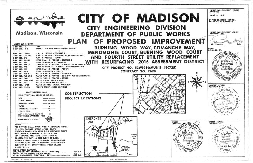
CITY OF MADISON CITY ENGINEERING DIVISION DEPARTMENT OF PUBLIC WORKS PLAN OF PROPOSED IMPROVEMENT
 PUBLIC Ji'v/PROVEMENT PROJECT APPROVED Madison, Wisconsin CITY OF MADISON CITY ENGINEERING DIVISION DEPARTMENT OF PUBLIC WORKS PLAN OF PROPOSED IMPROVEMENT JANUARY 3, 20I7 BY THE COMMON COUNCIL OF MADISON,
PUBLIC IMPROVEMENT PROJECT APPROVED CITY OF MADISON v CITY ENGINEERING DIVISION DEPARTMENT OF PUBLIC WORKS PROFILES N BIRCHWOOD POINT PHASE 10
 PUBLC MPROVEMENT PROJECT APPROVED CTY OF MADSON v CTY ENGNEERNG DVSON DEPARTMENT OF PUBLC WORKS Madison, Wisconsin PLAN OF PROPOSED NDEX OF SHEETS ii.j (J (/) f 1 TTLE SHEET NO. DlD4 DETALS SHEET NO. PlP5
STANDARD BID ITEM NUMBERS
 10701 TRAFFIC CONTROL LUMP SUM 10702 Traffic Control for Storm Sewer Installation LUMP SUM 10703 Traffic Control for Water Main Installation LUMP SUM 10704 Traffic Control for Sanitary Sewer Installation
Pipe Product Catalog Table of Contents
 Pipe Product Catalog Table of Contents Section A: Drawing #: Page Description A1 Reinforced Concrete Pipe A3 Storm Manhole Sizing Chart (48" - 96") A3.1 Storm Manhole Sizing Chart (108" - 144") A4 48"
UTILITY AND STREET CONSTRUCTION PLAN REQUIREMENTS SECTION 1
 UTILITY AND STREET CONSTRUCTION PLAN REQUIREMENTS SECTION 1 ENGINEERING STANDARDS FOR UTILITY AND STREET CONSTRUCTION PLANS MARCH 2014 CONSTRUCTION PLAN SHEET FORMAT REQUIREMENTS REPRODUCIBLE MYLAR 1.
Engineering and Construction Services Division Construction Drawings for Sewers and Watermains. T No. Revision T No. Revision Remarks All T drawings
 Engineering and Construction Services Division Construction Drawings for Sewers and Watermains Revision No. 8 April All T drawings New title block for each drawing is now standardized. Revision numbers
Appendix C Construction Details
 7172 Kennedy Road Warrenton, Virginia 20187 Appendix C Construction Details November 2017 TABLE OF CONTENTS THRUST BLOCKS Anchorage for 11 1/4 o, 22 1/2 o & 45 o Upper Vertical Bends... AV 01 Buttresses
NEWTON COUNTY WATER AND SEWERAGE AUTHORITY RESIDENTIAL, COMMERCIAL, INSTITUTIONAL AND INDUSTRIAL SUBDIVISIONS CONSTRUCTION PLANS CHECK LIST
 NEWTON COUNTY WATER AND SEWERAGE AUTHORITY RESIDENTIAL, COMMERCIAL, INSTITUTIONAL AND INDUSTRIAL SUBDIVISIONS CONSTRUCTION PLANS CHECK LIST Project Name Checked By Date Designer Check List marks to be
MAINTENANCE HOLES, CATCH BASINS AND DITCH INLETS - MTC FORM 407 INDEX
 407-1 - MAINTENANCE HOLES, CATCH BASINS AND DITCH INLETS - MTC FORM 407 INDEX 407-1.1 GENERAL Tender Items Specifications Standard Drawings 407-1.1.1 Frame and Grate Selection 407-1.1.2 Selection of Structure
SECTION III STANDARD DRAWINGS ROYSE CITY GENERAL CONSTRUCTION NOTES & DETAILS
 9. STANDARD DETAILS SECTION III STANDARD DRAWINGS ROYSE CITY GENERAL CONSTRUCTION NOTES & DETAILS j:\clerical\royse city\1-4086 general services\168-tech const standards review\tcss manual\2018 tcss manual\sec-9a
CITY OF MUSKEGO DRAFTING STANDARDS
 CITY OF MUSKEGO DRAFTING STANDARDS GENERAL - These standards apply to all plans. 1. Plans must be prepared on sheets measuring 36 inch across and 22 inch to 24 inch high unless otherwise specified under
SECTION 095 SPECIFICATIONS DETAIL DRAWINGS. Index of Detail Drawings
 SECTION 095 SPECIFICATIONS DETAIL DRAWINGS Index of Detail Drawings Flat Top Manhole... 095-1 Splash Drop Manhole and Regular Drop Manhole... 095-2 Special Detail Splash Drop Manhole and Special Detail
UPDATE LOG FOR STANDARD DRAWINGS Item(s) Changed 6/1/18 STANDARD DRAWINGS
 Changed 6/1/18 STANDARD DRAWINGS") Date 6/1/18 STANDARD DRAWINGS UPDATE LOG FOR STANDARD DRAWINGS Item(s) Changed WATER STANDARD DRAWINGS Title Drawing Number Current Date Fire Hydrant and Appurtenance Locations, Improved Streets with Curb
Date 6/1/18 STANDARD DRAWINGS UPDATE LOG FOR STANDARD DRAWINGS Item(s) Changed WATER STANDARD DRAWINGS Title Drawing Number Current Date Fire Hydrant and Appurtenance Locations, Improved Streets with Curb
CONCRETE MANHOLES.
 CONCRETE CONCRETE SHAW PIPE produces circular, precast, concrete manholes in diameters 1050mmØ through 3000mmØ. Precast, concrete manholes are most frequently used for pipeline and sewer entry and are
PART 4 STANDARD DRAWINGS FOR CONSTRUCTION
 4.0. INTRODUCTION PART 4 STANDARD DRAWINGS FOR CONSTRUCTION In this document, Ivins City adopts the most recent edition (currently 2007), including all amendments, of the APWA Utah Chapter s Manual of
September 21, Mannik Smith Group 1771 North Dixie Highway Monroe, Michigan RE: LA Fitness City File No.: CVLP
 CITY OF ANN ARBOR, MICHIGAN Public Services Area / Engineering 301 E. Huron Street, P.O. Box 8647 Ann Arbor, Michigan 48107 Phone (734) 794-6410 Fax (734) 994-1744 Web: www.a2gov.org Printed on recycled
Plan Submittal and Review Checklist
 Improving quality of life today creating a better tomorrow Plan Submittal and Review Checklist Version 1.2 September 4, 2017 Contents Overview... 2 Plan Submittal Checklist... 2 Plan Review Checklist -
STORM M ANHOLE FOR 42" PIPE AND SM ALLER JOB NO. SHEET NO. DATE MARCH 2015 OF MIN OF 3 CRSES MAX OF 5 CRSES 30"MAX 3 OR 3.5 PRECAST ECCENTIC CONC
 01-APR-2015 13:33 = I:\MSV8i\Plotting\piblack.ptb V:\201001\\C\8x11_Howell_Det\stm_det01_8x11_st01.dgn TIME = MIN 3 CRSES MAX 5 CRSES 3 OR 3.5 PRECAST ECCENTIC CONC ID PIPE GRADE A CONC FILL 4" 8" 2-0"SUMP
CITY OF REEDLEY NEW DEVELOPMENT PLAN REVIEW CHECK LIST
 CITY OF REEDLEY NEW DEVELOPMENT PLAN REVIEW CHECK LIST Tract Number and Subdivision Name: Engineering Firm: Contact Person: Address: City: State: Zip: Phone No. Fax No. Assessor s Parcel Number(s) Tentative
VILLAGE OF VILLA PARK CENTRAL BOULEVARD IMPROVEMENTS LOCATION MAP (NOT TO SCALE) CORTESI AVE. MYRTLE AVE. CENTRAL BLVD.
 CORTESI AVE. MYRTLE AVE. CENTRAL BLVD.") Q:\VillaPark_IL\11283000 Astor-Myrtle Sewer Separation Preliminary Design\D.4 CAD\Sheets\North\1. Cover.dwg INDEX OF SHEETS 1 COVER 2 GENERAL NOTES 3 SUMMARY OF QUANTITIES 4 ALIGNMENT 5-9 DRAINAGE AND
Q:\VillaPark_IL\11283000 Astor-Myrtle Sewer Separation Preliminary Design\D.4 CAD\Sheets\North\1. Cover.dwg INDEX OF SHEETS 1 COVER 2 GENERAL NOTES 3 SUMMARY OF QUANTITIES 4 ALIGNMENT 5-9 DRAINAGE AND
B-PERMIT PLAN CHECK MANUAL
 B-PERMIT PLAN CHECK MANUAL 5. SEWER PLANS Sewer Plans are usually submitted in conjunction with Street Plans to meet the requirements of conditions imposed on a Planning or Zoning action. In some cases
Existing and proposed contours at 1-foot intervals. The fill and/or excavation quantities in cubic yards.
 PLAN REQUIREMENTS The plans for street design shall conform to the requirements of Sections 3 and 4. The following requirements shall also be shown on the plans where applicable. Road and Storm Plans:
City of Regina Standard Construction Specifications SECTION LIST OF SEWER STANDARD DRAWINGS
 City of Regina Standard Construction Specifications SECTION 14999 LIST OF SEWER STANDARD DRAWINGS S-1 No Drawing Feb/10 S-2 Precast Manhole 1050mm Dia. July/10 S-2B Precast Manhole 1200mm Dia. Jan/17 S-3
STANDARD CATCH BASIN GUTTER LINE CB INLET FRAME & GRATE, GROUTED TO GRADE RINGS AS REQ'D CONCRETE CURB FINISHED GRADE ASPHALT MAX 50 MIN
 CB INLET FRAME & GRATE, GROUTED TO GRADE RINGS AS REQ'D ASPHALT 20 GUTTER LINE CONCRETE CURB FINISHED GRADE PRECAST GRADE RINGS, 2 50 100 MAX PRECAST CB LID GROUT ALL AROUND CB LEAD, INSIDE & OUTSIDE OF
1.1 GENERAL RECORD DRAWING REQUIREMENTS
 Page 1 of 5 VILLAGE OF ROMEOVILLE RECORD DRAWINGS CHECKLIST PART I GENERAL Record drawings are required to provide a means of schematic verification that the intent of the approved engineering design has
City of Vaughan Engineering Department DESIGN STANDARD DRAWINGS
 City of Vaughan Engineering Department DESIGN STANDARD DRAWINGS March 2004 STANDARD DRAWINGS Partners With The Environment March 2004 FORWARD The March 2004 version of the City of Vaughan Design Standard
Miscellaneous. Demolition
 Public Improvements Miscellaneous 1 Mobilization L.S. ** 2 Clearing and Grubbing L.S. *** 3 Structural Concrete Incl. Reinforcing C.Y. $1,325.00 4 6" PVC Sleeves L.F. $26.00 Demolition 5 Remove Asphalt
Anne Arundel County Dept. of Inspections and Permits Water Sewer Plan Checklist
 Project Name Project Number Engineer Plans are to be designed based on the standards set forth in the Anne Arundel County Design Manual Standards and Specifications, and all other manuals as stipulated
2. Remove from the Standard Plate manual: Standard Plate Index, Sheets 1-4 of 4, Numerical Index of Standard Plates (August 31, 2012)
") MINNESOTA DEPARTMENT OF TRANSPORTATION DEVELOPED BY: Design Standards ISSUED BY: Office of Program Management & Technical Support, Design Support Section TRANSMITTAL LETTER NO. (12-04) MANUAL: Standard
MINNESOTA DEPARTMENT OF TRANSPORTATION DEVELOPED BY: Design Standards ISSUED BY: Office of Program Management & Technical Support, Design Support Section TRANSMITTAL LETTER NO. (12-04) MANUAL: Standard
Design Data 12M. Hydraulic Capacity of Precast Concrete Boxes. RISE, Millimeters. Span Millimeters
 Design Data 12M Hydraulic Capacity of Precast Concrete Boxes Under certain conditions the hydraulic or structural characteristics of reinforced concrete box sections offer advantages over the circular
"A" "A" SECTION "A-A" X-SECTION VERTICAL CURB (TYPE B) Village STREET & PAVEMENT STR-05. Engineering Department
 Village STREET & PAVEMENT STR-05. Engineering Department") 1" 1/2" PRE-MOLDED NON-EXTRUDING JOINT FILLLER AT EXPANSION JOINTS (MAXIMUM 50' SPACING) 2" R "A" SEE NOTE 3 0.5" 1/8" R (TYP) DEPRESSED 1.5" PAVEMENT THICKNESS 3.5" 5.0" "A" 2" MINIMUM STONE CUSHION GRADATION
1" 1/2" PRE-MOLDED NON-EXTRUDING JOINT FILLLER AT EXPANSION JOINTS (MAXIMUM 50' SPACING) 2" R "A" SEE NOTE 3 0.5" 1/8" R (TYP) DEPRESSED 1.5" PAVEMENT THICKNESS 3.5" 5.0" "A" 2" MINIMUM STONE CUSHION GRADATION
Town of Westlake Construction Plans Review Checklist
 CONSTRUCTION PLANS CONTENTS All Drawings 24 x 36 Cover Sheet Final Plat Site Plan Demolition Plan Utility Plan Drainage Area Map and Calculations Paving Plan & Profile Sheets Storm Drain Plan & Profile
Type A. BWSC CAD Standards for Site Plans (Design and As-Built) Format. Scale. Fonts, Linetypes, Shapes
 Format. Scale. Fonts, Linetypes, Shapes") BWSC CAD Standards for Site Plans (Design and As-Built) Type A The following CAD standards are for Type A application and involve no work in Public Street, except for connection(s) to the Boston Water
BWSC CAD Standards for Site Plans (Design and As-Built) Type A The following CAD standards are for Type A application and involve no work in Public Street, except for connection(s) to the Boston Water
INSTRUCTIONS: 1. Record the transmittal letter number, date, and subject on the transmittal record sheet located in the front of the manual.
 MINNESOTA DEPARTMENT OF TRANSPORTATION DEVELOPED BY: Design Standards ISSUED BY: Office of Technical Support Design Services Section TRANSMITTAL LETTER NO. (0-03) MANUAL: Standard Plates DATED: September
Authorized Agent: City of Manassas Check List Attached: Contact: Address: Phone Number: Fax Number: Developer s Name: Phone Number:
 CITY OF MANASSAS DEPARTMENT OF COMMUNITY DEVELOPMENT DEVELOPMENT SERVICES DIVISION 9027 Center Street Room 201 Manassas, Virginia, 20110 Phone: 703-257-8278 Fax: 703-257-5831 Application Date: APPLICANT
SCHEDULE 10 ENGINEERING DRAWING SUBMISSION
 SCHEDULE 10 ENGINEERING DRAWING SUBMISSION Subdivision, Development and Servicing Bylaw No. 1535 10. ENGINEERING DRAWING SUBMISSIONS TABLE OF CONTENTS 1.0 General 3 1.1. Introduction 3 1.2. General Requirements
CONSTRUCTION SPECIFICATION FOR MAINTENANCE HOLE, CATCH BASIN, DITCH INLET, AND VALVE CHAMBER INSTALLATION
 ONTARIO PROVINCIAL STANDARD SPECIFICATION METRIC OPSS 407 NOVEMBER 2013 CONSTRUCTION SPECIFICATION FOR MAINTENANCE HOLE, CATCH BASIN, DITCH INLET, AND VALVE CHAMBER INSTALLATION TABLE OF CONTENTS 407.01
Section E NSPS MODEL STANDARDS FOR TOPOGRAPHIC SURVEYS Approved 3/12/02
 Section E NSPS MODEL STANDARDS FOR TOPOGRAPHIC SURVEYS Approved 3/12/02 1. INTRODUCTION This standard is written to provide the professional surveyor (Surveyor) and the client with a guideline for producing
City of Massillon Site Plan Checklist
 City of Massillon Site Plan Checklist The following information MUST be included with all Site Plans submitted for review and processing in order to constitute a complete Site Plan Package. Incomplete
CITY OF BEVERLY HILLS Department of Public Works and Transportation Civil Engineering Division STREET/ALLEY IMPROVEMENT PLAN REVIEW CHECKLIST
 CITY OF BEVERLY HILLS Department of Public Works and Transportation Civil ing Division STREET/ALLEY IMPROVEMENT PLAN REVIEW CHECKLIST The following checklist consists of the minimum requirements for preparation
SUPPLEMENTARY STANDARD DETAIL DRAWINGS
 CITY OF MAPLE RIDGE DESIGN AND CONSTRUCTION DOCUMENTS Part 4 SUPPLEMENTARY STANDARD DETAIL DRAWINGS September 2015 Updated: October 2015 THIS PAGE INTENTIONALLY LEFT BLANK City of Maple Ridge Supplementary
Manhole or Catch Basin Type A & B Cone Sections Precast - Design F Manhole or Catch Basin Cover (Reducer Cone Section Precast) Design D
 Design D") MINNESOTA DEPARTMENT OF TRANSPORTATION DEVELOPED BY: Design Standards ISSUED BY: Office of Program Management and Technical Support, Design Support Section TRANSMITTAL LETTER NO. (14-02) MANUAL: Standard
MINNESOTA DEPARTMENT OF TRANSPORTATION DEVELOPED BY: Design Standards ISSUED BY: Office of Program Management and Technical Support, Design Support Section TRANSMITTAL LETTER NO. (14-02) MANUAL: Standard
 6'' W 8'' W 8'' W 4'' SAN 4'' SAN 2'' W 6'' W 6'' W INSTALL C.U. PAD (SEE MECHANICAL). M FM FM FM FM FM FM FM FM FM FM FM FM FM FM FM FM FM FM FM FM FM FM FM FM FM FM FM FM FM FM FM FM TOP OF TOP OF SW
Project Name: County File No.: Checked by: For: Date:
 Project Name: County File No.: Checked by: For: Date: Print name Firm or agency Items noted in the checklist shall be considered the minimum amount of information necessary for submission of construction
DIVISION APPROVED MATERIAL LIST AND STANDARD DETAILS
 DIVISION 400 - APPROVED MATERIAL LIST AND STANDARD DETAILS Section 403 - STANDARD DETAILS TABLE OF CONTENTS DIVISION 400, Section 403 - STANDARD DETAILS SECTION DETAIL NOS. Application Table 403-1 I. Concrete
Standard Plate 7036 is discontinued. It is replaced by Standard Plan Pedestrian Curb Ramp Details.
 DEVELOPED BY: Design Standards ISSUED BY: Office of Program Management & Technical Support, Design Support Section TRANSMITTAL LETTER NO. (12-02) MANUAL: Standard Plates DATED: May 11, 2012 SUBJECT: Standard
18" 1.5" 3"R 11.5" 10" 3-1/2" MINIMUM STONE CUSHION GRADATION CA-6
 18" 1.5" 3"R 1.5" 4"R 1" 11.5" 10" 13.5" 5" 3-1/2" MINIMUM STONE CUSHION GRADATION CA-6 NOTES: 1. REINFORCEMENT: PROVIDE TWO (2) #4 REINFORCING BARS CONTINUOUS BETWEEN EXPANSION JOINTS, WITH LOCATION SPACING
CITY OF BEVERLY HILLS Department of Public Works and Transportation Civil Engineering Division STORM DRAIN IMPROVEMENT PLAN REVIEW CHECKLIST
 CITY OF BEVERLY HILLS Department of Public Works and Transportation Civil ing Division STORM DRAIN IMPROVEMENT PLAN REVIEW CHECKLIST The following checklist consists of the minimum requirements for preparation
SECTION G ESTIMATE OF QUANTITIES
 PROJECT STATE OF SOUTH DAKOTA NH 2115(45)87 SHEET G2 TOTAL SHEETS G27 SECTION G ESTIMATE OF QUANTITIES BID ITEM NUMBER ITEM QUANTITY UNIT 009E0010 Mobilization Lump Sum LS 560E0068 7'x3' Precast Concrete
BRASELTON WATER AND WASTEWATER DEPARTMENT CONSTRUCTION PLAN REVIEW CHECKLIST May 2006
 Project Name: BRASELTON WATER AND WASTEWATER DEPARTMENT CONSTRUCTION PLAN REVIEW CHECKLIST May 2006 Phase: Unit: # Lots: Development Type (residential, commercial, industrial, etc.) Braselton Project No.
Charlotte County Utilities DESCRIPTION
 As-built Drawings / Surveyor 1. Electronic copy of survey data in tabular form of the utility assets 2. A signed and sealed letter with the following statement: "I hereby certify that the as-built location
FOR SERVICE BOXES IN CONCRETE DRIVEWAYS, SEE NOTE Min. COVER UNDER DITCHES. 600 Min. COVER
 WOOD SERVICE MARKER STAKE (50 x 00) PAINTED BLUE PL mm FROM PROPERTY LINE STANDARD CONCRETE SERVICE BOX WITH EXTENSION AS REQ'D 00 FINISHED GROUND/ROAD SURFACE FOR SERVICE BOXES IN CONCRETE DRIVEWAYS,
Immediately following the Committee of the Whole meeting Mukwonago Municipal Building/Board Room, 440 River Crest Court
 Dated 06-29-17 SPECIAL VILLAGE BOARD MEETING Notice of Meeting and Agenda Wednesday, July 5, 2017 Time: Place: Immediately following the Committee of the Whole meeting Mukwonago Municipal Building/Board
KC Water Rules and Regulations For Water Main Extensions and Relocations
 KC Water Rules and Regulations For Water Main Extensions and Relocations MAY 2017 NOTE: Changes from 2016 are highlighted in yellow and appear on Pages 5, 8, 10-11, 13, and 15. Additional changes made
ACSA PLAN REVIEW CHECKLIST (Guideline Only) (4) Standard water and sewer general plan notes (attached).
 (4) Standard water and sewer general plan notes (attached).") ACSA PLAN REVIEW CHECKLIST (Guideline Only) Revised: December 3, 2015 General (1) Proper Title (2) Vicinity map on first sheet. (3) Date and latest plan revision. (4) Standard water and sewer general plan
ACSA PLAN REVIEW CHECKLIST (Guideline Only) Revised: December 3, 2015 General (1) Proper Title (2) Vicinity map on first sheet. (3) Date and latest plan revision. (4) Standard water and sewer general plan
SECTION 100 PRELIMINARY CONSIDERATIONS & INSTRUCTIONS
 SECTION 100 PRELIMINARY CONSIDERATIONS & INSTRUCTIONS 101 General 102 Submittal Requirements A. Initial Submittal B. Second Submittal 103 Plan Requirements A. Subdivisions B. Site Plans 104 Approval of
This addendum forms a part of the Contract Documents dated: August 10, 2012.
 Addendum # 1 Date Issued: August 28, 2012 Issued By: Project: Owner: Renker Eich Parks Architects 1609 Dr. Martin Luther King Street North St. Petersburg, Florida 33704 Ph# (727) 821-2986 Fax # (727) 896-4911
SUBJECT: Standard Plate 9102 Turf Establishment Areas At Pipe Culvert Ends
 MINNESOTA DEPARTMENT OF TRANSPORTATION DEVELOPED BY: Design Standards ISSUED BY: Office of Project Management and Technical Support, Design Support Section TRANSMITTAL LETTER NO. (17-03) MANUAL: Standard
LOWNDES COUNTY ENGINEERING PLAN REVIEW CHECKLIST. Design Professional: Phone: Developer: Phone: 2 nd Submittal (No Fee)
") MEMORANDUM MICHAEL B. FLETCHER, P.E. COUNTY ENGINEER 327 N. Ashley Street Valdosta, GA 31601 Telephone: (229) 671-2424 Fax: (229) 245-5299 mfletcher@lowndescounty.com LOWNDES COUNTY ENGINEERING PLAN REVIEW
MEMORANDUM MICHAEL B. FLETCHER, P.E. COUNTY ENGINEER 327 N. Ashley Street Valdosta, GA 31601 Telephone: (229) 671-2424 Fax: (229) 245-5299 mfletcher@lowndescounty.com LOWNDES COUNTY ENGINEERING PLAN REVIEW
RECORD DRAWINGS REVISED TO CONFORM TO CONSTRUCTION RECORDS PROVIDED BY CONTRACTOR GMG BY DATE 11/13 CRS NO.
 CELL: (715) 803-8009 MABOSI@WISCONSINPUBLICSERVICE.COM CELL: (715) 573-7806 CHVIRCKS@WISCONSINPUBLICSERVICE.COM CALVIN.KLADE@FTR.COM DGAU@KRONENWETTER.COM SCOTT OLSEN (715) 302-1348 S REVISED TO CONFORM
SECTION III SUBMITTALS AND APPROVALS
 SECTION III SUBMITTALS AND APPROVALS In order to expedite the approval process of new water distribution system and sanitary sewer collection system extensions, the Hilton Head No. 1 Public Service District
CHAPTER 11. Plan Standards
 CHAPTER 11 Plan Standards A. Introduction The city requires uniform public improvement plans for ease of record keeping and understanding. The following standards govern most plan submittals to the city.
ACWWA DRAWING SUBMITTAL INFORMATION - UTILITY DRAWING REQUIREMENTS
 ACWWA DRAWING SUBMITTAL INFORMATION - UTILITY DRAWING REQUIREMENTS Detailed construction drawings for system extensions shall be prepared for approval with a submittal to the Authority. All construction
MSD STANDARD DRAWINGS LOUISVILLE AND JEFFERSON COUNTY METROPOLITAN SEWER DISTRICT 700 WEST LIBERTY STREET LOUISVILLE, KENTUCKY
 MSD M etr o p olitan S e w e r Di s t r ict STANDARD DRAWINGS LOUISVILLE AND JEFFERSON COUNTY METROPOLITAN SEWER DISTRICT 700 WEST LIBERTY STREET LOUISVILLE, KENTUCKY 40203-1911 STANDARD DRAWINGS DIVISION
SECTION 39 - MANHOLES TABLE OF CONTENTS
 SECTION 39 - MANHOLES TABLE OF CONTENTS Section Page 39-1 GENERAL... 39.1 39-2 PRECAST CONCRETE MANHOLES... 39.1 39-2.01 Precast Concrete Sewer Manholes... 39.1 39-2.02 Precast Concrete Storm Drain Manholes...
WATER STRUCTURE LEGAL & SURVEY TOPOGRAPHY/GRADING LANDSCAPE/VEGETATION
 REVISION IDENTIFIER DETAIL LABEL CALLOUT LABEL 1 SHEET ABANDONED ASBESTOS CEMENT BALK OF WALK BEGINNING OF CURVE BENCH MARK BUILDING CAPACITY CAST IRON CATCH BASIN CATCH BASIN MANHOLE CENTER LINE CERTIFICATE
A1.1 FOX GARAGE VAN VAN VAN VAN 11/16/ WASHINGTON BLVD ST. LOUIS, MO REVISIONS FLOOR PLAN - LEVEL /01/14
 BUILDING FLOOR PLAN TES: 1. ALL DIMENSIONS ARE TO FACE OF CONCRETE OR CENTERLINE OF COLUMN (U). 2. SEE ENLARGED STAIR PLANS (A2.1-A2.3) FOR DETAILED INFORMATION T SHOWN. 3. SEE FINISH ELEVATIONS (A3.1-A3.2)
Sewer Line Extension Permit Design Checklist
 CHECKLIST C1 Revised 4/7/2017 Sewer Line Extension Permit Design Checklist DISCLAIMER - This checklist is provided to Consulting Engineers for the express purpose of assisting them in compiling sewer line
MTJ Outdoor Baggage Claim
 MTJ Outdoor Baggage Claim 915 S. Tenth St. Montrose, CO 8101 p: (970) 29-1980 f: (970) 797-6811 www.motleyarc.com Drawings and Dimensions 1. ATTENTION ALL USERS OF THESE DRAWINGS, GENERAL CONTRACTORS,
3. The PAC (Permit Application Center) will notify the design professional of plan review results.
 will notify the design professional of plan review results.") Planning and Development Dept. Infrastructure Division P.O. Box 11706, or 155 Johnston Street Rock Hill, South Carolina 29731-1706 Phone: 803-329-5515 FAX: 803-329-7228 www.cityofrockhill.com AS-BUILT
Planning and Development Dept. Infrastructure Division P.O. Box 11706, or 155 Johnston Street Rock Hill, South Carolina 29731-1706 Phone: 803-329-5515 FAX: 803-329-7228 www.cityofrockhill.com AS-BUILT
ROUTES: 65 SECTIONS: miles in length. THE FOLLOWING ITEMS AND APPROXIMATE QUANTITIES ARE INVOLVED:
 ARKANSAS DEPARTMENT OF TRANSPORTATION CA0801 HWY. 110 - CLINTON (WIDENING) (S) FEDERAL AID PROJECT ACNHPP-0071(31) THE PURPOSE OF THIS PROJECT IS TO WIDEN HIGHWAY 65 IN VAN BUREN COUNTY. THIS PROJECT CONSISTS
Oil-Water Separator Design Checklist
 CHECKLIST C3 Revised 5/2/2016 Oil-Water Separator Design Checklist DISCLAIMER - This checklist is provided to Consulting Engineers for the express purpose of assisting them in compiling private oil-water
Grease Interceptor Design Checklist
 CHECKLIST C2 Revised 5/2/2016 Grease Interceptor Design Checklist Public Works DISCLAIMER - This checklist is provided to Consulting Engineers for the express purpose of assisting them in compiling private
Current Standard Plates including Transmittal Letters are available on the web at:
 MINNESOTA DEPARTMENT OF TRANSPORTATION DEVELOPED BY: Design Standards ISSUED BY: Office of Project Management and Technical Support, Design Support Section TRANSMITTAL LETTER NO. (17-04) MANUAL: Standard
Utility Structures. Utility vaults, trenches, transformer pads Electrical Pole Bases and switching cubicles
 Utility Structures Utility vaults, trenches, transformer pads Electrical Pole Bases and switching cubicles PRODUCT GUIDE & TECHNICAL REFERENCE MANUAL Providing the right solutions. UTILITY STRUCTURES Perfect
APPENDIX 4. Checklists. Township of King Design Criteria and Standard Detail Drawings
 APPENDIX 4 Checklists Township of King Design Criteria and Standard Detail Drawings Township of King Design Criteria and Standard Detail Drawings APPENDIX 4 CHECKLISTS Engineering Submissions : The following
Anne Arundel County Dept. of Inspections and Permits Storm Drain Checklist
 Project Name Project Number Engineer Plans are to be designed based on the standards set forth in the Anne Arundel County Design Manual Standards and Specifications, and all other manuals as stipulated
SUBJECT: Standard Plates 4132, 4155, Drainage Structures and Castings Info
 MINNESOTA DEPARTMENT OF TRANSPORTATION DEVELOPED BY: Design Standards ISSUED BY: Office of Project Management and Technical Support, Design Support Section TRANSMITTAL LETTER NO. (18-01) MANUAL: Standard
SUBJECT: Standard Plate Turf Establishment Areas (at Pipe Culvert Ends)
") MINNESOTA DEPARTMENT OF TRANSPORTATION DEVELOPED BY: Design Standards ISSUED BY: Office of Program Management and Technical Support, Design Support Section TRANSMITTAL LETTER NO. (14-01) MANUAL: Standard
MINNESOTA DEPARTMENT OF TRANSPORTATION DEVELOPED BY: Design Standards ISSUED BY: Office of Program Management and Technical Support, Design Support Section TRANSMITTAL LETTER NO. (14-01) MANUAL: Standard
GAMA Engineering Inc Weston Road, Suite 35B Vaughan, Ontario L4L 9P1
 St. Thomas Retirement Home SWM Brief (2017) Storm Water Management and Servicing Design Report For St. Thomas Retirement Home 292 Wellington Street, St. Thomas, ON N5R 2S9 PREPARED FOR SUNRAY GROUP PREPARED
ADDENDUM No. 1. ITB No Northside Interceptor Condition Assessment. Due: February 1, 2018 at 10:00 A.M. (Local Time)
") ADDENDUM No. 1 ITB No. 4521 Northside Interceptor Condition Assessment Due: February 1, 2018 at 10:00 A.M. (Local Time) The following changes, additions, and/or deletions shall be made to the Invitation
ADDENDUM No. 1 ITB No. 4521 Northside Interceptor Condition Assessment Due: February 1, 2018 at 10:00 A.M. (Local Time) The following changes, additions, and/or deletions shall be made to the Invitation
WATER & SEWER CONSTRUCTION SITE PLAN DESIGN SUMMARY COMMERCIAL & RESIDENTIAL
 WATER & SEWER CONSTRUCTION SITE PLAN DESIGN SUMMARY COMMERCIAL & RESIDENTIAL This summary is not all inclusive of the requirements set forth by the York County Planning & Development Services, York County
SUBDIVISION APPLICATION FOR DRT SUBMITTAL PUBLIC WORKS DEPARTMENT
 Case #: SUBDIVISION APPLICATION FOR DRT SUBMITTAL PUBLIC WORKS DEPARTMENT 171 North Ross Street, Suite 200 Auburn, AL 36830 (334) 501-3000 ~ Fax: (334) 501-7294 Applicant Name: Mailing Address: Email Address:
City of Regina Standard Construction Specification SECTION 2999 LISTING OF ROADWAY STANDARD DRAWINGS
 City of Regina Standard Construction Specification SECTION 2999 LISTING OF ROADWAY STANDARD DRAWINGS R-1 Alternate Pavement Structures July/10 R-2 Typical Cross Sections for Asphaltic Concrete Pavements
SAUSALITO-MARIN CITY SANITARY DISTRICT MISCELLANEOUS UPGRADES PROJECT. Addendum No. 2
 SAUSALITO-MARIN CITY SANITARY DISTRICT MISCELLANEOUS UPGRADES PROJECT Addendum No. 2 The following shall modify the Contract Documents. The work shall be accomplished in accordance with such modifications.
10010 RECORD DRAWING INFORMATION
 SECTION 10000 RECORD DRAWING CHECK LIST All entities who construct public infrastructure, private streets, private storm drain collection systems and travel lanes, shall submit to the Town of Cary Engineering
Engineering Department DRAWING STANDARD SPECIFICATIONS
 DRAWING STANDARD SPECIFICATIONS June 2017 City of Surrey TABLE of CONTENTS Page i Page 1 INTRODUCTION... 1 1.1 Overview... 1 1.2 Measurements / Units... 1 1.3 Hardcopy and Digital Template... 1 2 DRAWING
MAY J. Collins Engineering Associates, LLC San Jose Blvd. Jacksonville, Florida 32223
 PROJECT LOCATION: 95 NOCATEE PARKWAY PONTE VEDRA, FL. 38 J. Collins Engineering Associates, LLC 56-3 San Jose Blvd. Jacksonville, Florida 32223 NOT TO SCALE 904-262-42 sm sm ON DRAWING WHERE SECTION OR
Public Works City of Lebanon, Tennessee; Department of Public Works
 SECTION 1 GENERAL 1. DEFINITIONS Public Works City of Lebanon, Tennessee; Department of Public Works City City of Lebanon, Wilson County, Tennessee City Engineer Employed by the City of Lebanon, Registered
IOWA CITY WASTEWATER TREATMENT PLANT RELOCATION PROJECT NORTH PLANT SALVAGE AND DEMOLITION PHASE CITY OF IOWA CITY FEBRUARY, 2015
 IOWA CITY WASTEWATER TREATMENT PLANT RELOCATION PROJECT No Record Drawing Comments by Veit for this Sheet! FOR FEBRUARY, 2015 VEIT Record Drawings Demolition Project Manager: Jason Mueller Demolition Superintendent:
Valley Road Main Replacement
 Bonding Provided Construction Co., Construction, Construction, 5% 5% 5% 5% 5% 5% 5% acknowledged 2 - Bidder Acknowledges Receipt of Addendums there was only 1 Affadivit of Preferential Bidders Status not
HUSSEY GAY BELL SAVANNAH, GEORGIA
 HUSSEY GAY BELL SAVANNAH, GEORGIA ------------------------------------------------------------------------------------------------------------ ADDENDUM NO. 3 TO THE CONTRACT DOCUMENTS AND TECHNICAL SPECIFICATIONS
Government Of Newfoundland & Labrador Municipal Water, Sewer And Roads Master Construction Specifications
 PAGE NO. : 1 OF 4 Revision Date: July 2009 STANDARD DRAWINGS TABLE OF CONTENTS DRAWING # DESCRIPTION 0030............ Work Adjacent to Roadway 0040............ Work at the Edge of Roadway 0050............
Council Policy Engineering Drawing Submission Requirements
 POLICY 265 City of Kelowna 1435 Water Street Kelowna, BC V1Y 1J4 250 469-8500 kelowna.ca Council Policy Engineering Drawing Submission Requirements APPROVED June 4, 2001 RESOLUTION: R375/10/04/26 REPLACING:
STATE UNIVERSITY CONSTRUCTION FUND
 DIRECTIVE 1C-12 Issue date: August 2012 1. General SURVEY, MAPPING AND UTILITY LOCATING This Directive has been developed as a general guide for the survey and mapping effort required for Fund projects.
3. DESIGN SPECIFICATIONS
 Schedule H to Bylaw 7452, Subdivision Bylaw Page 10 3. DESIGN SPECIFICATIONS 3.1 General 3.1.1 The Design Specifications apply to the design of sanitary sewers, storm drains, waterworks, roadways, and
DESIGN GUIDELINES (SD) COUNTY OF ALAMEDA PUBLIC WORKS AGENCY 399 ELMHURST STREET HAYWARD, CA
 COUNTY OF ALAMEDA PUBLIC WORKS AGENCY 399 ELMHURST STREET HAYWARD, CA") DESIGN GUIDELINES (SD) COUNTY OF ALAMEDA PUBLIC WORKS AGENCY 399 ELMHURST STREET HAYWARD, CA 94544-1395 PUBLIC WORKS DESIGN GUIDELINES TABLE OF CONTENTS SD-100 SERIES SPECIAL DRAWINGS SD-100 8/1991 SILT
DESIGN GUIDELINES (SD) COUNTY OF ALAMEDA PUBLIC WORKS AGENCY 399 ELMHURST STREET HAYWARD, CA 94544-1395 PUBLIC WORKS DESIGN GUIDELINES TABLE OF CONTENTS SD-100 SERIES SPECIAL DRAWINGS SD-100 8/1991 SILT
MINIMUM C/L RADII OF CURVATURE OF LOCAL ROADS IN SUBDIVISIONS
 75m 70m 65m 60m DEFLECTION ANGLE C/L RADII OF CURVATURE 55m 50m 45m 40m 35m 30m 25m 20m 15m 90 80 70 60 50 40 30 20 10 0 DEFLECTION ANGLE - MINIMUM C/L RADII OF CURVATURE OF LOCAL ROADS IN SUBDIVISIONS
INSTALLATION INSTRUCTIONS. March 2016 FOR FURTHER QUESTIONS, PLEASE CALL
 March 2016 INSTALLATION INSTRUCTIONS FOR FURTHER QUESTIONS, PLEASE CALL 775 440 2025 JENSEN WATER RESOURCES 521 Dunn Circle, Sparks, NV 89431 JensenPumps.com Figure 1: This illustration shows a complete
Minimum Drawing & Electronic Submittal Requirements For Record Drawings /As-Builts
 Minimum Drawing & Electronic Submittal Requirements For Record Drawings /As-Builts PUBLIC WORKS ENGINEERING DEPARTMENT Revised: February 1, 2017 MINIMUM DRAWING REQUIREMENTS A. GENERAL PLAN REQUIREMENTS: