SURVEYING THE UNDERGROUND
|
|
|
- Juliana Cox
- 5 years ago
- Views:
Transcription
1 SURVEYING THE UNDERGROUND An Introduction to the Practice of Subsurface Utility Engineering Maryland Society of Surveyors Maryland Society of Professional Engineers Joint Conference October 8, 2015 Michael T. Maguire, MA, LS John P. Berrettini
2 SURVEYING THE UNDERGROUND Agenda Introduce ASCE & Subsurface Utility Engineering (SUE). Look at some technical aspects of locating UG utilities Case studies / practical experiences Answer questions about locating UG utilities

3 THE CHALLENGE Source: Federal Laboratory Consortium for Technology Transfer COMPLEX UTILITY LAYERS UNDERGROUND

4 THE CHALLENGE


5 INCREASING COMPLEXITY UNDERGROUND


6 INCREASING COMPLEXITY UNDERGROUND
7 WHAT ARE TRADITIONAL METHODS TO MAP UTILITIES? Records research Field survey of surface features Valves, hand boxes, meters, manholes, hydrants Perhaps locate One Call marks if found in field Fit record information to surface evidence & marks Disclaim responsibility for underground utilities per plan BUT, NOW THERE IS A BETTER WAY!


8 CI/ ASCE 38-02
9 CI/ ASCE Standard Guideline for the Collection and Depiction of Existing Subsurface Utility Data 2003 American Society of Civil Engineers Increasing complexity of national subsurface infrastructure Subsurface unknowns create risks on construction projects Many records are inaccurate, incomplete, out of date Utility Owners (One Call-811) in most states a construction excavation period service Post-design & after bidding Some States have Designer Tickets Informational only, USUALLY - NO LIABILITY FOR INACCURATE INFORMATION When conflicts arise during construction solutions are costly change orders, extra work orders, insurance payouts and contingency pricing
10 ASCE Scope of Consensus standard Defines quality of utility depictions Associated attribute data Addresses implementation Methods Available technologies Communication of data Intent of Establish classification system to describe quality of data associated with existing subsurface utilities Facilitate Communication about the quality of utility data needed or provided for construction documents
11 KEY TERMS Designating Interpret the presence of subsurface utility through surface geophysical methods Mark its approximate horizontal position on the ground Locating Expose and record the precise vertical and horizontal location of a utility. Utility Quality Level A professional opinion of the quality and reliability of utility information.
12 QUALITY LEVEL D QL D Information derived from existing records State and local utility departments One Call Center Landowners Internet Utility companies Types of Records Construction Drawings Conduit, Distribution and Transmission Maps As-builts Oral Histories May include a field visit to look for visual cues to utility systems Composite drawing plotted for schematic representation without registration to ground features all representation are at QL D May be adequate for preliminary planning purposes
13 QUALITY LEVEL C QL C Perform QL D tasks Identify and field survey, process and plot utility surface features Correlate applicable utility records to surveyed features considering record utility system geometries Determine conflicts between records and surface features and attempt to resolve discrepancies, if possible The Information obtained by surveying and plotting visible above-ground utility features and by using professional judgment in correlating this information to QL D May result in a combination of QL C and QL D depictions
14 QUALITY LEVEL B QL B Perform QL C Tasks May be done in conjunction with QL B activities Select an appropriate suite of surface geophysical methods Apply surface geophysics to search for utilities Interpret the geophysics in the field or office depending on method Mark and survey indications of subsurface utilities Depict approximate horizontal positions of all detected utilities Surveys of depicted positions must be merged with field records & historic documentation through professional analysis and judgment to produce final mapping. QLB data to be reproducible by surface geophysics at any point of depiction Positions surveyed to applicable project standards Recommend to project owner when additional methods such as test holes may be needed to determine positions May result in a combination of QL B, C & D depictions
15 QUALITY LEVEL A QL A Perform QL B tasks at appropriate project locations Excavate test holes to expose the utility to be measured Minimally intrusive excavation Air-vacuum & sometimes hydro-vacuum extraction Hand dig Sometimes as built measurements during construction Actual exposure or verification of previously exposed and surveyed utilities and subsequent measurement of subsurface utilities, usually at a specific point Horizontal and vertical position, existing grade at ground surface, size and configuration of utility, material type, general condition, ground condition encountered Precise horizontal and vertical positions reported Accuracy is typically set to 15-mm (0.05 feet) vertical and to the specified horizontal survey and mapping accuracy of the project
16 ENGINEER S RESPONSIBILITIES Advise owner of potential utility impacts on project Inform and educate the project owner about quality levels costs and benefits of each Recommend QL, scope, depiction required quality level may vary across project Recommend formatting of deliverables to be maintained across the project team and throughout the project life Discuss sequence of acquiring appropriate quality level data Recommend quality level upgrades as indicated by design needs Follow one-call statutes, if any apply; e.g. designer ticket number in VA.
17 OWNER S RESPONSIBILITIES Review scope with engineer; amend or approve as appropriate Assist in contact with existing utility owners; (may improve access to records) Review quality levels with project team; approve format of deliverables for all team members Notify the engineer of suspected deficiencies in the utility depiction if familiar with site and utility systems in place Furnish utility information to utility owners for utility marking for construction (one-call systems)
18 ASCE Originally established for transportation (highway) projects Generally public utilities (with records) involved Can be applied to site specific design projects Shortage of available (private) utility records add to challenges on site specific projects Patterns of utility configurations are often less regular (and predictable) than in or through transportation corridors
19 SURVEYING THE UNDERGROUND Professional SUE providers use ASCE as their professional framework for methods and procedures to meet standards of professional care SUE is distinctly different from One Call Meticulous care in research, field investigation from mains to mechanical room, search & trace unknowns, all conductors, active & abandoned, survey, map, correlate with records Comprehensive consideration of all utilities; known and unknown; public & private, active & abandoned QL labels inform designer about the reliability of utility Test holes are excavated to validate utility designating Comprehensive investigation enables SUE providers to assume professional liability
20 QUESTIONS? What s next Locating Theory and Practice QLB and QLA
21 LOCATING THEORY & PRACTICE Basic introduction to common detection theory and methods Electromagnetic Pipe and Cable Detection Ground Penetrating Radar Utility Designating Quality Level B making a more accurate, more complete horizontal map Utility Locating (Test Holes) Quality Level A when accuracy and precision are critical and to validate mapping; including depth/elevation
22 ELECTROMAGNETIC PIPE AND CABLE LOCATING SOME DEFINITIONS: Signal: a flow of electrical current at a specific frequency on conductors such as metallic pipes, wires or cables Conductor: a linear object that electrical current can travel through (in our case a utility pipe, wire or cable) Magnetic Field: a cylindrical field that forms around a conductor when current is flowing through it


23 DETECTING MAGNETIC FIELDS


24 APPLYING THE SIGNAL DIRECT CONNECT, CLAMP INDUCTION AND SURFACE INDUCTION
25 INFLUENCING FACTORS: ELECTROMAGNETIC PIPE AND CABLE LOCATING Depth of bury Shallow - stronger field easily detected Deep weaker field, more difficult to detect Physical access to utility surface induction may be the only option for applying signal Utility type and material The easiest utilities to detect are conductive cables and pipes with minimal restrictions to current travel. Conductor congestion both above and below ground causes signal bleed to adjacent conductors making it difficult to interpret the multitude of magnetic fields Pavement and soil characteristics rebar and slag

26 BASIC GPR PRINCIPALS Electromagnetic pulses of energy are emitted from transmitting antenna downward through the ground The pulses reflect back from objects that contrast with the surrounding soils The reflections are detected by the receiving antenna and processed through circuitry and software to produce an image of the reflections


27 MODERN GPR UNITS

28 CLASSIC GPR DATA A SINGLE SCAN (CROSS SECTION)
29 EM VS GPR COMPARISON EM Pipe and Cable Locators Works in variety of soils Utilities need to be conductive (or snaked with conductive rodder) Small diameter lines can be detected Instrument detects magnetic field Employed on nearly all investigations Useful for linear utilities (lines) Lower cost to detect most utilities Ground Penetrating Radar Wet or conductive soils will limit or prevent use Non-conductive utilities can be detected Small diameter utilities hard to detect Instrument detects reflected wave Employed when circumstances dictate Useful for tanks, drums, vaults, voids, etc. Higher cost to detect fewer utilities
30 DESIGNATING QL B TYPICAL APPROACH Records Research (utilities known to exist) Field Investigation Geophysical Properties Pipe & Cable Locators Visible Light Ground Penetrating Radar APWA-ULCC Field Marking (Red electric, bluewater, etc.) Field Sketch and Survey & Map Documented Results Represent Professional Opinion Most Reliable Non-excavated Utility Location Includes Private, Public, Abandoned Utilities


31 FIELD EQUIPMENT A VARIETY OF EQUIPMENT TO COVER A WIDE RANGE OF UTILITY LOCATING SCENARIOS

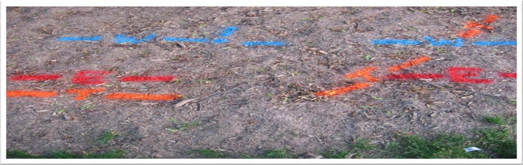


32 UTILITY DESIGNATION: MARKINGS CAREFULLY PLACED


33 FIELD SKETCHING, SURVEY & CAD PROCESSING

34 FIELD/ OFFICE COLLABORATION Debrief field crew for unique site issues and problems QL D search efforts Troubleshoot difficult detection scenarios Compare field sketch to CAD results Compare CAD to records Correlate field data with records Assign QL to utility depictions (QL-B is the goal with QL-C or D as needed Provide mapping in AutoCAD or MicroStation
35 SURFACE FEATURES DON T TELL THE WHOLE STORY!
36 Open /inspect manholes, handholes, vaults, pedestals, cabinets Connect, clamp or induce on all observable utilities and trace Snake with rods and sondes as needed and trace 2 person sweep seek out & trace and ID unknowns Field technicians needed to use the full bag of tricks
37 SUMMARY QUALITY LEVEL B A Standardized Procedure Records Research Field Investigation Direct Connect Clamp Induce (Sweep) Field Marking Field Sketch Data Collection (Total Station, RTK GPS) Map & Correlate With Records Review & Edit Deliver In AutoCAD Or MicroStation
38 LOCATING QL A AIR/ VACUUM TEST HOLES THE BASIC STEPS Perform test hole setup at the site. Test hole plan based on QL B info? QL C or QL D info? Notify the One Call - 811utility notification center. Plan traffic control. Apply for an excavation permit. Coordinate with utility inspectors. Schedule the rig, test hole crew and survey crew. Compile results and report to client / engineer

39 VACUUM EXCAVATION TRUCK MOUNTED UNIT

40 VACUUM EXCAVATION PORTABLE UNIT


41 DOWN-HOLE VIEW UTILITY EXPOSED


42 TEST HOLE OPERATIONS SET MARKER, MEASURE AND DOCUMENT BACKFILL, COMPACT AND RESTORE HORIZONTAL AND VERTICAL POSITION
43 WHY AIR/ VACUUM EXCAVATION? COMPARED TO MECHANICAL/ BACKHOE ETC. Less impact to utilities Safer than hand digging Safer than mechanical digging Less impact to property and public Small hole test hole not test pit Small work footprint Neat work area (soils contained) Short duration occupancy (9 to 3 restrictions) Low cost (particularly in paved roadways) Effective for majority of utility measurement needs

44 TEST HOLE DATA SHEET

45 DETECTION ACCURACY 0.4 +/- OFFSET FROM DESIGNATED POSITION ACTUAL POSITION OF WATER LINE DESIGNATED POSITION OF WATER LINE IS APPROX. 0.4 FROM ACTUAL POSITION
46 SUMMARY QL A Engineering / Survey Grade Data Most Reliable Determination Of Utility Data however Point Specific Results May not accurately predict utility characteristics beyond test hole location. QL B may still be needed. Minimizes Risk Of Damage To Exposed Utilities May Be Used For A Variety Of Structure Types Most often used when precision is needed for conflict identification and resolution


47 SUE LEGEND & NOTES
48 SUE IMPLEMENTATION Possible Engineer s Note Subsurface utilities are depicted by their Quality Levels in accordance with ASCE based on professional designating services provided by A/I/DATA on August 5, Contractors shall validate subsurface utility data to their own satisfaction. designating and locating if test holes performed as part of services provided. Show Quality Level definitions in drawing legend. Use labeling conventions in plan view. These steps help distinguish paint on the ground from professional services rendered Design excellence is built on quality base data

49 QUESTIONS? FHWA ASCE standards/list/ COMMON GROUND ALLIANCE UNDERGROUND CONSTRUCTION UNDERGROUND FOCUS ACCURATE INFRASTRUCTURE DATA, INC Batavia Farm Road, Suite 200 Baltimore, MD (TOLL FREE) (PHONE) (FAX) THE END?
SURVEYING THE UNDERGROUND
 SURVEYING THE UNDERGROUND An Introduction to ASCE 38-02 and the Practice of Subsurface Utility Engineering ACECMD March 28, 2018 Presented by: Art Worthman A. Morton Thomas & Associates, Inc. John Berrettini
Work Type Definition and Submittal Requirements Work Type: Subsurface Utility Engineering (SUE)
") MUST be qualified under Minnesota Department of Transportation Prequalification Program - Work Type 15.1 Subsurface Utility Engineering The first section, Work Type Definition, provides a detailed explanation
MUST be qualified under Minnesota Department of Transportation Prequalification Program - Work Type 15.1 Subsurface Utility Engineering The first section, Work Type Definition, provides a detailed explanation
STATE UNIVERSITY CONSTRUCTION FUND
 DIRECTIVE 1C-12 Issue date: August 2012 1. General SURVEY, MAPPING AND UTILITY LOCATING This Directive has been developed as a general guide for the survey and mapping effort required for Fund projects.
SPECIFICATIONS FOR THE INSTALLATION OF CONDUIT SYSTEMS IN RESIDENTIAL SUBDIVISIONS. Notification of Completed Conduit Sections
 SPECIFICATIONS FOR THE INSTALLATION OF CONDUIT SYSTEMS IN RESIDENTIAL SUBDIVISIONS Section 1 Definitions 2 Scope of Work 3 Extent of Work 4 Inspection and Performance of Work 5 Trenching 6 Duct Installation
Subsurface Utility Engineering and 3D Utility Mapping
 Subsurface Utility Engineering and 3D Utility Mapping Subsurface Utility Engineering: A branch of engineering practice that involves managing certain risks associated with utility mapping and appropriate
Strategic City Wide Mapping of Underground Assets using Ground Penetrating Radar. Mark Bell
 Strategic City Wide Mapping of Underground Assets using Ground Penetrating Radar Mark Bell XXV International Federation of Surveyors Congress, Kuala Lumpur, Malaysia, 16 21 June 2014 TOPICS GPR background
Geophysical Survey Rock Hill Bleachery TBA Site Rock Hill, South Carolina EP-W EPA, START 3, Region 4 TABLE OF CONTENTS Section Page Signature
 Geophysical Survey Rock Hill Bleachery TBA Site Rock Hill, South Carolina EP-W-05-054 EPA, START 3, Region 4 Prepared for: Tetra Tech EM, Inc. October 12, 2012 Geophysical Survey Rock Hill Bleachery TBA
Report. Mearns Consulting LLC. Former Gas Station 237 E. Las Tunas Drive San Gabriel, California Project # E
 Mearns Consulting LLC Report Former Gas Station 237 E. Las Tunas Drive San Gabriel, California Project #1705261E Charles Carter California Professional Geophysicist 20434 Corisco Street Chatsworth, CA
STREETSCAPE FEASIBILITY TERMS OF REFERENCE
 Introduction STREETSCAPE FEASIBILITY TERMS OF REFERENCE As outlined in the Official Plan, Section 9, Build A Desirable Urban Form, Mississauga will transform the public realm to create a strong sense of
Division 1 - General Requirements
 Division 1 - General Requirements I - Design Standards 01 30 10 Ground Disturbance Standard Revision Record Ver. Rev. Date Description By Chk d App d* 1 Final Draft CK * Approval sign-off must be from
Utility Locating Terminology & Equipment Guide. Utility Survey Corp.
 Utility Locating Terminology & Equipment Guide Utility Survey Corp. Contents Utility Locating Terminology Utility Locating Toning or Scoping Scanning X Ray the Ground & Ground Penetrating Radar 3 4 5 6
EXCAVATION AND BACKFILL
 Standard Specification 2565.3, 2451, and 1805 A basic understanding of specifications is needed to properly replace the disturbed soil and restore the condition of the excavated area. The size of the disturbed
The use of high frequency transducers, MHz, allowing the resolution to target a few cm thick in the first half meter suspect.
 METHODOLOGY GPR (GROUND PROBING RADAR). In recent years the methodology GPR (Ground Probing Radar) has been applied with increasing success under the NDT thanks to the high speed and resolving power. As
COLLEGE COLLEGE OF ENGINEERING & COMPUTER SCIENCE ASSOCIATE DEAN: DR. MOHAMMAD ILYAS GEOMATIC ENGINEERING PROGRAM
 COLLEGE COLLEGE OF ENGINEERING & COMPUTER SCIENCE DEAN: DR. KARL STEVENS ASSOCIATE DEAN: DR. MOHAMMAD ILYAS GEOMATIC ENGINEERING PROGRAM INTERIM PROGRAM DIRECTOR: DR. DON LEONE P.E. STAFF & FUTURE ENGINEERS,
SPECIFICATIONS FOR NEW UNDERGROUND RESIDENTIAL DISTRIBUTION SYSTEMS
 Page: 4-1 4.0 URD Process and Documentation Requirements 4.1 Process Steps The process of developing underground distribution facilities in a residential area consists of 10 major steps, which are summarized
Advanced Utility Locating Technologies (R01B)
") Advanced Utility Locating Technologies (R01B) Jacob Sheehan Senior Geophysicist Olson Engineering Phil Sirles Principal Geophysicist Olson Engineering Introduction: Utility Bundle Overview SHRP2 Strategic
Advanced Utility Locating Technologies (R01B) Jacob Sheehan Senior Geophysicist Olson Engineering Phil Sirles Principal Geophysicist Olson Engineering Introduction: Utility Bundle Overview SHRP2 Strategic
November 13, Hindu Temple, LTD Arbor Street Omaha, Nebraska Attn: Subject:
 November 13, 2017 Hindu Temple, LTD 13010 Arbor Street Omaha, Nebraska 68144-0000 Attn: Subject: Srini Mallipudi / mallipudis@gmail.com Underground Utility Survey Report Hindu Temple - 13010 Arbor Street,
CHAPTER 14: TRAFFIC SIGNAL STANDARDS Introduction and Goals Administration Standards Standard Attachments 14.
 14.00 Introduction and Goals 14.01 Administration 14.02 Standards 14.03 Standard Attachments 14.1 14.00 INTRODUCTION AND GOALS The purpose of this chapter is to outline the City s review process for traffic
Customer Requirements Commercial Secondary Service
 Application Installation requirements for commercial services from Tacoma Power overhead or underground facilities. It applies to new construction or upgrades of older services. Electrical service may
.1 Applicability: These criteria shall be applied as follows:
 DESIGN CRITERIA DIVISION 4800 STREET LIGHTING 4801 GENERAL: These criteria shall be adhered to for the design of all publiclyfinanced or privately-financed traffic signal systems to be installed in the
3M Dynatel Locating and Marking Products
 3M Dynatel Locating and Marking Products 1420 Series ID Markers EMS 1420 Marker Locator 2200M Series Locators 2200M-iD Series Locators Dynatel Strengths 30+ years experience in locating Inventors of passive
Architectural Design Process
 Architectural Design Process Custom Residential A. Schematic Design Phase Pre-Design Meeting Site Analysis Site Survey Conceptual Design & Project Scope Design Program Guideline Project Team Formation
Automated Machine Guidance
 Design Manual Chapter 5 - Roadway Design 5H - Automated Machine Guidance 5H-1 Automated Machine Guidance A. Concept Automated machine guidance (AMG) for grading is a process in which grading equipment,
APPENDIX 1: CONSTRUCTION PLAN CHECKLIST
 APPENDIX 1: CONSTRUCTION PLAN CHECKLIST October 2017 APPENDIX A APPENDIX 1: CONSTRUCTION PLAN CHECKLIST ALL PLANS Plans on 24-inch by 36-inch paper (Originals shall be transmitted on a CD as an electronic
BRASELTON WATER AND WASTEWATER DEPARTMENT CONSTRUCTION PLAN REVIEW CHECKLIST May 2006
 Project Name: BRASELTON WATER AND WASTEWATER DEPARTMENT CONSTRUCTION PLAN REVIEW CHECKLIST May 2006 Phase: Unit: # Lots: Development Type (residential, commercial, industrial, etc.) Braselton Project No.
ACSA PLAN REVIEW CHECKLIST (Guideline Only) (4) Standard water and sewer general plan notes (attached).
 (4) Standard water and sewer general plan notes (attached).") ACSA PLAN REVIEW CHECKLIST (Guideline Only) Revised: December 3, 2015 General (1) Proper Title (2) Vicinity map on first sheet. (3) Date and latest plan revision. (4) Standard water and sewer general plan
ACSA PLAN REVIEW CHECKLIST (Guideline Only) Revised: December 3, 2015 General (1) Proper Title (2) Vicinity map on first sheet. (3) Date and latest plan revision. (4) Standard water and sewer general plan
CHAPTER 11 PRELIMINARY SITE PLAN APPROVAL PROCESS
 CHAPTER 11 PRELIMINARY SITE PLAN APPROVAL PROCESS 11.01.00 Preliminary Site Plan Approval 11.01.01 Intent and Purpose 11.01.02 Review 11.01.03 Application 11.01.04 Development Site to be Unified 11.01.05
Section E NSPS MODEL STANDARDS FOR TOPOGRAPHIC SURVEYS Approved 3/12/02
 Section E NSPS MODEL STANDARDS FOR TOPOGRAPHIC SURVEYS Approved 3/12/02 1. INTRODUCTION This standard is written to provide the professional surveyor (Surveyor) and the client with a guideline for producing
Advanced Ground Investigation Techniques to Help Limit Risk or Examine Failure. Advanced Subsurface Investigations
 Advanced Ground Investigation Techniques to Help Limit Risk or Examine Failure Overview Introduction What is geophysics? Why use it? Common Methods Seismic Ground Radar Electrical Case Studies Conclusion
SECTION 5 TRANSFORMERS
 SECTION 5 TRANSFORMERS Necessary transformers will be installed and maintained by The City of Aspen. The City of Aspen will not furnish transformers unless they are of standard size and voltage as established
PART XII: TOPOGRAPHIC SURVEYS
 PART XII: TOPOGRAPHIC SURVEYS 12.1 Purpose and Scope The purpose of performing topographic surveys is to map a site for the depiction of man-made and natural features that are on, above, or below the surface
Radiodetection. Fundamental principles and techniques in buried utility location
 Fundamental principles and techniques in buried utility location Canada 344 Edgeley Blvd. Unit 34 Concord, Ontario L4K 4B7 1-800-665-7953 Pipe and Cable Locators don't find pipes and cables...? 2 ...they
a step change in Ground Penetrating Radar technology Guido Manacorda Engineering Manager
 The ORFEUS Project: a step change in Ground Penetrating Radar technology to locate buried utilities Guido Manacorda Engineering Manager IDS Ingegneria dei Sistemi i SpA Key issues Many ypp pipes and cables
A Report on the Ground Penetrating Radar Survey 205 Little Plains Road Southampton, NY
 A Report on the Ground Penetrating Radar Survey 205 Little Plains Road Southampton, NY November 18, 2016 Conducted by Robert W. Perry TOPOGRAPHIX, LLC Hudson, NH Requested by Southampton Town Historical
AGENDA Cemetery Board 206 Toronto St. S., Markdale, Ontario June 11, :00 p.m.
 AGENDA Cemetery Board 206 Toronto St. S., Markdale, Ontario June 11, 2008-4:00 p.m. Page 1. CALL TO ORDER 2. ADDITIONS TO OR DELETIONS FROM THE AGENDA 3. ADOPTION OF AGENDA 4. DECLARATION OF CONFLICT OR
SUBSURFACE MAPPING. Presenters: Thomas Kevin Hanna, PLS. Paul J. Emilius Jr., PLS CP
 SUBSURFACE MAPPING Presenters: Thomas Kevin Hanna, PLS Paul J. Emilius Jr., PLS CP February 2 nd 2011 1 Existing Underground Utilities Abound! Power, Telecommunications, Gas/Propane, Petroleum, Sanitary
CITY OF LOMPOC DEVELOPMENT ASSISTANCE BROCHURE ENCROACHMENT PERMITS AND PUBLIC IMPROVEMENT PLANS
 CITY OF LOMPOC DEVELOPMENT ASSISTANCE BROCHURE E-10 ENCROACHMENT PERMITS AND PUBLIC IMPROVEMENT PLANS The City of Lompoc has determined that the Engineering Division should administer and issue Encroachment
Suggested Traffic Signal Design Procedures Indefinite Delivery (ID) Contract Locations and Conventional Signal Contract Locations
 Contract Locations and Conventional Signal Contract Locations") Suggested Traffic Signal Design Procedures Indefinite Delivery (ID) Contract Locations and Conventional Signal Contract Locations MDOT SUGGESTED TRAFFIC SIGNAL DESIGN PROCEDURE INDEFINITE DELIVERY INSTALLATION
Suggested Traffic Signal Design Procedures Indefinite Delivery (ID) Contract Locations and Conventional Signal Contract Locations MDOT SUGGESTED TRAFFIC SIGNAL DESIGN PROCEDURE INDEFINITE DELIVERY INSTALLATION
Exploration Beyond Expectation. Geo-Carte Radar Technology Pvt. Ltd.
 Exploration Beyond Expectation Geo-Carte Radar Technology Pvt. Ltd. Problem Unknown distribution network of underground pipeline in India 32% Damage of pre-existing underground utilities during laying
SPECIFICATIONS FOR THE INSTALLATION OF CONDUIT SYSTEM(S) FOR STREETLIGHTS. 1 Definitions. 2 Scope of Work. 3 Extent of Work
 FOR STREETLIGHTS. 1 Definitions. 2 Scope of Work. 3 Extent of Work") SPECIFICATIONS FOR THE INSTALLATION OF CONDUIT SYSTEM(S) FOR STREETLIGHTS Section 1 Definitions 2 Scope of Work 3 Extent of Work 4 Inspection and Performance of Work 5 Trenching 6 Duct Installation 7 Backfilling
SPECIFICATIONS FOR THE INSTALLATION OF CONDUIT SYSTEM(S) FOR STREETLIGHTS Section 1 Definitions 2 Scope of Work 3 Extent of Work 4 Inspection and Performance of Work 5 Trenching 6 Duct Installation 7 Backfilling
Archaeo-Geophysical Associates, LLC
 Geophysical Survey at the Parker Cemetery Rockwall, Texas. AGA Report 2010-6 Report Submitted To: Texas Cemetery Restoration 10122 Cherry Tree Dr. Dallas, Texas 75243 May 14, 2010 Chester P. Walker, Ph.D.
MILL HILL ARTS VILLAGE
 OWNER CIVIL ENGINEER MACON-BIBB URBAN DEVELOPMENT AUTHORITY ALEX MORRISON, EXECUTIVE DIRECTOR 200 CHERRY STREET, SUITE 300 MACON, GA 31201 OFFICE PHONE : (478) 803-2402 TRIPLE POINT ENGINEERING DAN WALLACE,
Accurate Utility Depth Measurements Using the Spar 300
 Accurate Utility Depth Measurements Using the Spar 3 This Application Note addresses how to obtain accurate subsurface utility depths using the model-based methods employed by the Spar 3. All electromagnetic
Abandoned Facility Management
 Abandoned Facility Management 2014 AASHTO Subcommittee on Right of Way, Utilities and Outdoor Advertising Control Conference James H. Anspach, P.G. Cardno ASCE Definitions Abandoned facility shall mean
Advances in NDE Technology WHATS NEW?
 Advances in NDE Technology WHATS NEW? Glen Simula, Owner GS Infrastructure, Inc. The state of America s deteriorating infrastructure presses us to find solutions to assess, with limited funds and resources.
Customer Requirements RF Antenna Installations
 Application Terms Attachment requirements and clearances on the Pole for Radio Frequency (RF) antenna equipment installations. This standard is intended to allow electrical workers to perform their normal
GPR SURVEY METHOD. Ground probing radar
 The ground penetrating radar (GPR - Ground Probing Radar) is a geophysical method used to investigate the near surface underground. Thanks to its high degree of resolution, the GPR is the most effective
Tri-band ground penetrating radar for subsurface structural condition assessments and utility mapping
 Tri-band ground penetrating radar for subsurface structural condition assessments and utility mapping D. Huston *1, T. Xia 1, Y. Zhang 1, T. Fan 1, J. Razinger 1, D. Burns 1 1 University of Vermont, Burlington,
7. Consider the following common offset gather collected with GPR.
 Questions: GPR 1. Which of the following statements is incorrect when considering skin depth in GPR a. Skin depth is the distance at which the signal amplitude has decreased by a factor of 1/e b. Skin
GNSS CONSTRUCTION INSPECTION EQUIPMENT
 Project: Jamaica-Winhall STP 2904(1) Advertised Date: 5/30/2018 GNSS CONSTRUCTION INSPECTION EQUIPMENT DESCRIPTION. This work shall consist of furnishing, configuring, installing, maintaining, and removing
Existing and proposed contours at 1-foot intervals. The fill and/or excavation quantities in cubic yards.
 PLAN REQUIREMENTS The plans for street design shall conform to the requirements of Sections 3 and 4. The following requirements shall also be shown on the plans where applicable. Road and Storm Plans:
Option 1. Design Options are diverse e.g. new route alignments covering a wide area. Option 2. Design Options are restricted
 MINIMUM STANDARD Z/16 SURVEY SPECIFICATIONS 1. GENERAL This specification sets out the Consultant s requirements for topographical survey (ground and aerial) for the Detailed Business Case (DBC) and Pre-Implementation
SECTION DEWATERING TANKAGE PART 1 - GENERAL 1.1 RELATED DOCUMENTS
 SECTION 31 23 19 - DEWATERING TANKAGE PART 1 - GENERAL 1.1 RELATED DOCUMENTS A. Drawings and general provisions of the Contract, including General and Supplementary Conditions and Division 1 Specification
1. Report No. FHWA/TX-05/ Title and Subtitle PILOT IMPLEMENTATION OF CONCRETE PAVEMENT THICKNESS GPR
 1. Report No. FHWA/TX-05/5-4414-01-3 4. Title and Subtitle PILOT IMPLEMENTATION OF CONCRETE PAVEMENT THICKNESS GPR Technical Report Documentation Page 2. Government Accession No. 3. Recipient s Catalog
CITY OF TUMWATER 555 ISRAEL RD. SW, TUMWATER, WA (360)
") CITY OF TUMWATER 555 ISRAEL RD. SW, TUMWATER, WA 98501 (360) 754-4180 Email: cdd@ci.tumwater.wa.us WATER-SEWER-STREET-STORM (IN CITY) Submittal Checklist TUM - RCVD BY DATE STAMP APPLICANT INFORMATION
CITY OF TUMWATER 555 ISRAEL RD. SW, TUMWATER, WA 98501 (360) 754-4180 Email: cdd@ci.tumwater.wa.us WATER-SEWER-STREET-STORM (IN CITY) Submittal Checklist TUM - RCVD BY DATE STAMP APPLICANT INFORMATION
Appendix I Geophysical Survey
 DRAFT IRM PRE- DESIGN INVESTIGATION DATA SUMMARY REPORT NATIONAL GRID FULTON MUNICIPAL WORKS FORMER MGP SITE APRIL 2013 Appendix I Geophysical Survey GEOPHYSICAL SURVEY FULTON MUNICIPAL WORKS FORMER MGP
ELECTROMAGNETIC FIELD APPLICATION TO UNDERGROUND POWER CABLE DETECTION
 ELECTROMAGNETIC FIELD APPLICATION TO UNDERGROUND POWER CABLE DETECTION P Wang *, K Goddard, P Lewin and S Swingler University of Southampton, Southampton, SO7 BJ, UK *Email: pw@ecs.soton.ac.uk Abstract:
1.1 GENERAL RECORD DRAWING REQUIREMENTS
 Page 1 of 5 VILLAGE OF ROMEOVILLE RECORD DRAWINGS CHECKLIST PART I GENERAL Record drawings are required to provide a means of schematic verification that the intent of the approved engineering design has
Minimum Drawing & Electronic Submittal Requirements For Record Drawings /As-Builts
 Minimum Drawing & Electronic Submittal Requirements For Record Drawings /As-Builts PUBLIC WORKS ENGINEERING DEPARTMENT Revised: February 1, 2017 MINIMUM DRAWING REQUIREMENTS A. GENERAL PLAN REQUIREMENTS:
GPR SYSTEM USER GUIDE AND TROUBLESHOOTING GUIDE
 GPR SYSTEM USER GUIDE AND TROUBLESHOOTING GUIDE Implementation Report 5-4414-01-1 Project Number 5-4414-01 Subsurface Sensing Lab Electrical and Computer Engineering University of Houston 4800 Calhoun
LOWNDES COUNTY ENGINEERING PLAN REVIEW CHECKLIST. Design Professional: Phone: Developer: Phone: 2 nd Submittal (No Fee)
") MEMORANDUM MICHAEL B. FLETCHER, P.E. COUNTY ENGINEER 327 N. Ashley Street Valdosta, GA 31601 Telephone: (229) 671-2424 Fax: (229) 245-5299 mfletcher@lowndescounty.com LOWNDES COUNTY ENGINEERING PLAN REVIEW
MEMORANDUM MICHAEL B. FLETCHER, P.E. COUNTY ENGINEER 327 N. Ashley Street Valdosta, GA 31601 Telephone: (229) 671-2424 Fax: (229) 245-5299 mfletcher@lowndescounty.com LOWNDES COUNTY ENGINEERING PLAN REVIEW
Ground Penetrating Radar (GPR) By Dr. Eng. Zubair Ahmed
 By Dr. Eng. Zubair Ahmed") Ground Penetrating Radar (GPR) By Dr. Eng. Zubair Ahmed Acknowledgement Golder Associates, Whitby, Ontario Stantec Consulting, Kitchener, Ontario Infrasense Inc. USA Geophysical Survey Systems Inc. (GSSI),
Ground Penetrating Radar (GPR) By Dr. Eng. Zubair Ahmed Acknowledgement Golder Associates, Whitby, Ontario Stantec Consulting, Kitchener, Ontario Infrasense Inc. USA Geophysical Survey Systems Inc. (GSSI),
SECTION TRACER WIRE FOR NONMETALLIC PIPE
 PART 1 GENERAL 1.1 DESCRIPTION A. The CONTRACTOR shall furnish and install a conductive tracer wire with all buried plastic water mains, services and appurtenances in accordance with the Water Utilities
Electromagnetic Induction
 Electromagnetic Induction Recap the motivation for using geophysics We have problems to solve Slide 1 Finding resources Hydrocarbons Minerals Ground Water Geothermal Energy SEG Distinguished Lecture slide
Survey Requirements. Design Guidelines and Standards. June Office of the University Architect
 Design Guidelines and Standards Survey Requirements June 2004 Office of the University Architect Construction Management P.O. Box 210181 Cincinnati, Ohio 45221-0181 Table of Contents Survey Requirements
UNIVERSITY OF ROCHESTER DESIGN STANDARDS FEBRUARY 29, 2012
 SECTION 01950 - RECORD DRAWINGS & SPACE FLOOR PLANS 1.1 RECORD DRAWINGS MATERIAL AND FORMAT A. Definition 1. Final record drawings, or as-builts, are drawings, which are revised to reflect the changes
WisDOT Research & Library Program
 WisDOT Research & Library Program 4802 Sheboygan Avenue, Room 104 research@dot.wi.gov PO Box 7915, Madison, WI 53707 www.wisdotresearch.wi.gov Transportation Synthesis Report & Literature Search Collection
9 LAND SURVEYING. 9.1 General. 9.2 Administrative Requirements Standards Meetings Survey Data Provided to the Design-Builder
 9 LAND SURVEYING 9.1 General The Design-Builder shall conduct all Work necessary to meet the requirements associated with land surveying, including Project and supplemental horizontal and vertical control
CITY OF LA MARQUE CHAPTER GRAPHIC REQUIREMENTS CONSTRUCTION PLAN AND MISCELLANEOUS REQUIREMENTS
 CITY OF LA MARQUE CHAPTER 2 -------------------------------------------- GRAPHIC REQUIREMENTS CONSTRUCTION PLAN AND MISCELLANEOUS REQUIREMENTS CHAPTER 2 ------------------------------------------------
Guidelines for the Preparation of ITS & Signal Plans by Private Engineering Firms
 Guidelines for the Preparation of ITS & Signal Plans by Private Engineering Firms INTRODUCTION Use the following Guidelines in conjunction with the ITS & Signals Scope of work provided in the Project Scoping
Suveying Lectures for CE 498
 Suveying Lectures for CE 498 SURVEYING CLASSIFICATIONS Surveying work can be classified as follows: 1- Preliminary Surveying In this surveying the detailed data are collected by determining its locations
B.2 MAJOR SUBDIVISION PRELIMINARY PLAN CHECKLIST
 B.2 MAJOR SUBDIVISION PRELIMINARY PLAN CHECKLIST YES* GENERAL SUBMISSION ITEMS Does the submission include: 1. Thirteen (13) copies of completed Application Form? 2. Thirteen (13) copies of the Preliminary
Customer Connection Guide Updates Effective May 2017
 This document provides a list of the updates to the EPCOR Distribution and Transmission Inc. (EDTI) Customer Connection Guide. If you have any questions, please contact EDTI Customer Engineering Services
REQUEST FOR PROPOSAL AERIAL PHOTOGRAPHY & DIGITAL MAPPING ROADS DEPARTMENT
 REQUEST FOR PROPOSAL AERIAL PHOTOGRAPHY & DIGITAL MAPPING ROADS DEPARTMENT The Cherokee Nation is requesting proposals from qualified professionals to provide aerial photography and digital mapping of
ADDENDUM NO. 3 PROJECT: COURTLAND PUMP STATION CONTRACT: IFB NO COM.00030
 ADDENDUM NO. 3 PROJECT: COURTLAND PUMP STATION CONTRACT: IFB NO. 2018-008-COM.00030 To: Prospective Bidders of Record Date: January 8, 2019 The following changes, additions, revisions, and/or deletions
Leica Digisystem Safe and fast location of underground services
 Leica Digisystem Safe and fast location of underground services Leica Digisystem Making Cable Avoidance Easier and Safer Every year site workers are injured due to inadvertently striking buried utilities
TOWN OF OAKVILLE FIRE ROUTE APPLICATION PACKAGE
 TOWN OF OAKVILLE FIRE ROUTE APPLICATION PACKAGE This application package contains: Page1. 2. 3. 4. 5. 6. 7. Application Process Description Minimum Fire Route Design Requirements Drawing Requirements Sample
CHECKLIST PRELIMINARY SUBDIVISION AND PRELIMINARY SITE PLAN
 N/A Waiver (1) Four (4) copies of application form. (2) Fifteen (15) copies of plan (3) Subdivision/site plan application fee & professional review escrow deposit (4) Variance application fee & professional
PS 1000 X-Scan Tips & Tricks. Quick Guide
 PS 1000 X-Scan Tips & Tricks Quick Guide en en QUICK GUIDE Tips & tricks 1. PS 1000 X-Scan Scanning on rough surfaces When the scanner is moved over a rough surface, the distance between the scanner and
ACWWA DRAWING SUBMITTAL INFORMATION - UTILITY DRAWING REQUIREMENTS
 ACWWA DRAWING SUBMITTAL INFORMATION - UTILITY DRAWING REQUIREMENTS Detailed construction drawings for system extensions shall be prepared for approval with a submittal to the Authority. All construction
F I S H E R R E S E A R C H L A B O R A T O R Y
 TW-82 DIGITAL LINE TRACER Operating Manual F I S H E R R E S E A R C H L A B O R A T O R Y CONTENTS Introduction...pg. 3 Transmitter...pg. 4-5 Receiver...pg. 6-8 Operating Instructions...pg. 9 Specifications...pg.
Charlotte County Utilities DESCRIPTION
 As-built Drawings / Surveyor 1. Electronic copy of survey data in tabular form of the utility assets 2. A signed and sealed letter with the following statement: "I hereby certify that the as-built location
MINIMUM DRAWING REQUIREMENTS FOR WATER AND SEWER LINE PROJECTS
 Public Works Department Water & Wastewater Services WATER & WASTEWATER ENGINEERING DIVISION 2555 West Copans Road Pompano Beach, Florida 33369 954-831-0745 FAX 954-831-0798/0925 MINIMUM DRAWING REQUIREMENTS
The above deliverables are to be provided as a zip file to your ILAWC Engineering Project Manager.
 Water Main Construction Projects The requirements and deliverables identified below are those for water main construction projects performed by Developers, Contractors, and Internal Illinois-American Water
STAFF User Manual. Manual Part #
 STAFF User Manual Manual Part # 030-00085-00 Introduction Congratulations on the purchase of your new STAFF Secondary Fault Locator. The STAFF is specially designed to detect conductor to earth/ground
UTILITY LOCATING EQUIPMENT
 RIDGID SEEKTECH LOCATING RECEIVERS RIDGID locating receivers feature an easy-to-use visual mapping display that allows you to locate utility lines and sondes/beacons with confidence. Use with a SeeSnake
PORT OF ST. HELENS SCAPPOOSE INDUSTRIAL AIRPARK PARALLEL TAXIWAY B RELOCATON AIP PROJECT ADDENDUM NO. 1
 PORT OF ST. HELENS SCAPPOOSE INDUSTRIAL AIRPARK PARALLEL TAXIWAY B RELOCATON AIP PROJECT 3-41-0056-024-2018 ADDENDUM NO. 1 Addendum No. 1 hereby amends the contract documents and drawings for the Scappoose
3 Dynatel M Series Locating and Marking System DOCUMENT NEW- TO- THE- WORLD TECHNOLOGY OBSOLETE DAMAGE PREVENTION PIN- POINT ACCURACY SAFETY
 3 Dynatel M Series Locating and Marking System NEW- TO- THE- WORLD TECHNOLOGY PIN- POINT ACCURACY SAFETY DAMAGE PREVENTION Introducing the 3M Dynatel M-iD Series Locating and Marking System. NEW TECHNOLOGY
A. Dewatering observation wells are part of dewatering allowance.
 SECTION 312319 - DEWATERING PART 1 - GENERAL 1.1 RELATED DOCUMENTS A. Drawings and general provisions of the Contract, including General and Supplementary Conditions and Division 01 Specification Sections,
CHAPTER F IVE ROBOTIC TOTAL STATION
 CHAPTER F IVE ROBOTIC TOTAL STATION 5 ROBOTIC TOTAL STATION 5 OVERVIEW If necessity is the mother of invention, then the invention of the Total Station robotic instrument truly fits the requirements of
Georgia Underground Marking Standards
 Georgia Underground Marking Standards PSC RULE 515-9-4.14 414 GUFPA PSC Rules AGENDA Marking Standards d Sufficient Particularity Educational Materials GUFPA Law and PSC Rule GUFPA- Dig Law Passed by the
SECTION DEWATERING PART 1 - GENERAL 1.1 RELATED DOCUMENTS
 SECTION 312319 - DEWATERING PART 1 - GENERAL 1.1 RELATED DOCUMENTS A. Drawings and general provisions of the Contract, including General and Supplementary Conditions and Division 01 Specification Sections,
TAXIWAY B NORTH ROAD RUNWAY TAXIWAY C NORTH ROAD VICINITY MAP. Plans Prepared By:
 CONSTRUCTION PLANS CITY OF NAPLES AUTHORITY (APF) NAPLES, COLLIER COUNTY, FLORIDA NAA BID NO. : TBD FAA AIP NO.: N/A FDOT FM NO.: N/A HANSON PROJ. NO. 15A0023 CITY OF NAPLES AUTHORITY BOARD OF COMMISSIONERS
BIM Introduction. Building Information Management Definitions, Applications and general information. Betty Bezos
 BIM Introduction Building Information Management Definitions, Applications and general information Betty Bezos betty@bezos.com 9/1/2017 1 9/1/2017 2 Innovations in BIM 3D Design: 3D visualizations allow
ROWAN UNIVERSITY 201 MULLICA HILL ROAD GLASSBORO, NEW JERSEY 08028
 THE CENTER FOR RESEARCH AND EDUCATION IN ADVANCED TRANSPORTATION ENGINEERING SYSTEMS (CREATEs) ISSUED FOR BID - CONTRACT - 02 201 MULLICA HILL ROAD GLASSBORO, NEW JERSEY 08028 ALL DIMENSIONS MUST BE VERIFIED
GROUND PENETRATING RADAR (GEORADAR) INSPECTION
 INSPECTION") - CIVIL ENGENEERING - GEOLOGY AND ENVIRONMENT - GROUND PENETRATING RADAR - LOSSES DETECTING RADAR SYSTEM - ARCHEOLOGY & CULTURAL HERITAGE - CARGO INSPECTION - LOSS CONTROL - CHEMICAL ANALYSIS - INDUSTRIAL
- CIVIL ENGENEERING - GEOLOGY AND ENVIRONMENT - GROUND PENETRATING RADAR - LOSSES DETECTING RADAR SYSTEM - ARCHEOLOGY & CULTURAL HERITAGE - CARGO INSPECTION - LOSS CONTROL - CHEMICAL ANALYSIS - INDUSTRIAL
3. DESIGN SPECIFICATIONS
 Schedule H to Bylaw 7452, Subdivision Bylaw Page 10 3. DESIGN SPECIFICATIONS 3.1 General 3.1.1 The Design Specifications apply to the design of sanitary sewers, storm drains, waterworks, roadways, and
SeekTech SR-60 SeekTech SR-20 NaviTrack Scout
 Locating Equipment RIDGID Receivers RIDGID locating receivers feature an easy to use visual mapping display that allows you to locate utility lines and sondes/ beacons with confidence. Use with a SeeSnake
RD8100 OPTIMUM PRECISION FOR DAMAGE PREVENTION
 PRECISION locators RD8100 OPTIMUM PRECISION FOR DAMAGE PREVENTION Since Radiodetection launched the first commercial, twin antenna, cable and pipe locators over 40 years ago, we have pioneered many technologies
Essential Skills: Reading and Interpreting Maps and Plans
 Essential Skills: Reading and Interpreting Maps and Plans Prepared for: NEW YORK STATE PLANNING FEDERATION April 14, 2015 Prepared by: BME ASSOCIATES Peter G. Vars, P.E. Stages of Plan Review Concept /