Trigger and data acquisition
|
|
|
- Melvyn David Osborne
- 5 years ago
- Views:
Transcription
1 Trigger and data acquisition N. Ellis CERN, Geneva, Switzerland 1 Introduction These lectures concentrate on experiments at high-energy particle colliders, especially the generalpurpose experiments at the Large Hadron Collider (LHC). These experiments represent a very challenging case that illustrates well the problems that have to be addressed in state-of-the-art high-energy physics (HEP) trigger and data-acquisition (T/DAQ) systems. This is also the area in which the author is working (on the trigger for the ATLAS experiment at LHC) and so is the example that he knows best. However, the lectures start with a more general discussion, building up to some examples from LEP that had complementary challenges to those of the LHC. The LEP examples are a good reference point to see how HEP T/DAQ systems have evolved in the last few years. Students at this school come from various backgrounds phenomenology, experimental data analysis in running experiments, and preparing for future experiments (including working on T/DAQ systems in some cases). These lectures try to strike a balance between making the presentation accessible to all, and going into some details for those already familiar with T/DAQ systems. 1.1 Definition and scope of trigger and data acquisition The T/DAQ is the online system that selects particle interactions of potential interest for physics analysis (trigger), and that takes care of collecting the corresponding data from the detectors, putting them into a suitable format and recording them on permanent storage (DAQ). Special modes of operation need to be considered, e.g., the need to calibrate different detectors in parallel outside of normal data-taking periods. T/DAQ is often taken to include associated tasks, e.g., run control, monitoring, clock distribution and book-keeping, all of which are essential for efficient collection and subsequent offline analysis of the data. 1.2 Basic trigger requirements As introduced above, the trigger is responsible for selecting interactions that are of potential interest for physics analysis. These interactions should be selected with high efficiency, the efficiency should be precisely known (since it enters in the calculation of cross-sections), and there should not be biases that affect the physics results. At the same time, a large reduction of rate from unwanted high-rate processes may be needed to match the capabilities of the DAQ system and the offline computing system. High-rate processes that need to be rejected may be instrumental backgrounds or high-rate physics processes that are not relevant for the analyses that one wants to make. The trigger system must also be affordable, which implies limited computing power. As a consequence, algorithms that need to be executed at high rate must be fast. Note that it is not always easy to achieve the above requirements (high efficiency for signal, strong background rejection and fast algorithms) simultaneously. Trigger systems typically select events 1 according to a trigger menu, i.e., a list of selection criteria an event is selected if one or more of the criteria are met. Different criteria may correspond to different signatures for the same physics process redundant selections lead to high selection efficiency and allow the efficiency of the trigger to be measured from the data. Different criteria may also reflect the wish to concurrently select events for a wide range of physics studies HEP experiments (especially those with large general-purpose detectors or, more precisely, detector systems) are really experimental facilities. Note that the menu has to cover the physics channels to be studied, plus additional data 1 The term event will be defined in Section 3 for now, it may be taken to mean the record of an interaction. 241
2 N. ELLIS samples required to complete the analysis (e.g., measure backgrounds, and check the detector calibration and alignment). 1.3 Basic data-acquisition requirements The DAQ system is responsible for the collection of data from detector digitization systems, storing the data pending the trigger decision, and recording data from the selected events in a suitable format. In doing so it must avoid corruption or loss of data, and it must introduce as little dead-time as possible ( dead-time refers to periods when interesting interactions cannot be selected see below). The DAQ system must, of course, also be affordable which, for example, places limitations on the amount of data that can be read out from the detectors. 2 Design of a trigger and data-acquisition system In the following a very simple example is used to illustrate some of the main issues for designing a T/DAQ system. An attempt is made to omit all the detail and concentrate only on the essentials examples from real experiments will be discussed later. Before proceeding to the issue of T/DAQ system design, the concept of dead-time, which will be an important element in what follows, is introduced. Dead-time is generally defined as the fraction or percentage of total time where valid interactions could not be recorded for various reasons. For example, there is typically a minimum period between triggers after each trigger the experiment is dead for a short time. Dead-time can arise from a number of sources, with a typical total of up to O(10%). Sources include readout and trigger dead-time, which are addressed in detail below, operational dead-time (e.g., time to start/stop data-taking runs), T/DAQ downtime (e.g., following a computer failure), and detector downtime (e.g., following a high-voltage trip). Given the huge investment in the accelerators and the detectors for a modern HEP experiment, it is clearly very important to keep dead-time to a minimum. In the following, the design issues for a T/DAQ system are illustrated using a very simple example. Consider an experiment that makes a time-of-flight measurement using a scintillation-counter telescope, read out with time-to-digital converters (TDCs), as shown in Fig. 1. Each plane of the telescope is viewed by a photomultiplier tube (PMT) and the resulting electronic signal is passed to a discriminator circuit that gives a digital pulse with a sharp leading edge when a charged particle passes through the detector. The leading edge of the pulse appears a fixed time after the particle traverses the counter. (The PMTs and discriminators are not shown in the figure.) Two of the telescope planes are mounted close together, while the third is located a considerable distance downstream giving a measurable flight time that can be used to determine the particle s velocity. The trigger is formed by requiring a coincidence (logical AND) of the signals from the first two planes, avoiding triggers due to random noise in the photomultipliers it is very unlikely for there to be noise pulses simultaneously from both PMTs. The time of arrival of the particle at the three telescope planes is measured, relative to the trigger signal, using three channels of a TDC. The pulses going to the TDC from each of the three planes have to be delayed so that the trigger signal, used to start the TDC (analogous to starting a stop-watch), gets there first. The trigger signal is also sent to the DAQ computer, telling it to initiate the readout. Not shown in Fig.1 is logic that prevents further triggers until the data from the TDC have been read out into the computer the so-called dead-time logic. 242
3 TRIGGER AND DATA ACQUISITION 2.1 Traditional approach to trigger and data acquisition The following discussion starts by presenting a traditional approach to T/DAQ (as might be implemented using, for example, NIM and CAMAC electronics modules 2, plus a DAQ computer). Note that this approach is still widely used in small test set-ups. The limitations of this model are described and ways of improving on it are presented. Of course, a big HEP experiment has an enormous number of sensor channels [up to O(10 8 ) at LHC], compared to just three in the example. However, the principles are the same, as will be shown later. Limitations of the T/DAQ system shown in Fig. 1 are as follows: 1. The trigger decision has to be made very quickly because the TDCs require a start signal that arrives before the signals that are to be digitized (a TDC module is essentially a multichannel digital stop-watch). The situation is similar with traditional analog-to-digital converters (ADCs) that digitize the magnitude of a signal arriving during a gate period, e.g., the electric charge in an analogue pulse the gate has to start before the pulse arrives. 2. The readout of the TDCs by the computer may be quite slow, which implies a significant dead-time if the trigger rate is high. This limitation becomes much more important in larger systems, where many channels have to be read out for each event. For example, if 1000 channels have to be read out with a readout time of 1 µs per channel (as in CAMAC), the readout time per event is 1 ms which excludes event rates above 1 khz. Measure ToF Beam Scintillation counters Initiate readout & Trigger TDC A delay B delay C delay Trigger has to get to TDC before signals A, B, C Delay may be cable Start TDC Fig. 1: Example of a simple experiment with its T/DAQ system The readout model of this traditional approach to T/DAQ is illustrated in Fig. 2, which shows the sequence of actions arrival of the trigger, arrival of the detector signals (followed by digitization and storage in a data register in the TDC), and readout into the DAQ computer. Since no new trigger can be accepted until the readout is complete, the readout dead-time is given by the product of the trigger rate and the readout time. 2 NIM and CAMAC modules are electronic modules that conform to agreed standards modules for many functions needed in a T/DAQ system are available commercially. 243
4 N. ELLIS 1. Trigger 1. Trigger 2. Signals 2. Signals (Digitizer) (Digitizer) Register Register Readout dead-time: Trigger rate readout time Readout dead-time: Trigger rate readout time 3. Read out 3. Read out Start TDC Start TDC ( Gate ( Gate ADC ) ADC ) Fig. 2: Readout model in the traditional approach 2.2 Local buffer The traditional approach described above can be improved by adding a local buffer memory into which the data are moved rapidly following a trigger, as illustrated in Fig. 3. This fast readout reduces the deadtime, which is now given by the product of the trigger rate and the local readout time. This approach is particularly useful in large systems, where the transfer of data can proceed in parallel with many local buffers (e.g., one local buffer for each crate of electronics) local readout can remain fast even in a large system. Also, the data may be moved more quickly into the local buffer within the crate than into the DAQ computer. Note that the dashed line in the bottom, right-hand part of Fig. 1 indicates this extension to the traditional approach the trigger signal is used to initiate the local readout within the crate. 1. Trigger 1. Trigger Start TDC ( Gate ADC ) Start TDC ( Gate ADC ) 2. Signals 2. Signals (Digitizer) Register (Digitizer) Register Readout dead-time: Trigger Readout rate dead-time: local readout time Trigger rate local readout time 3. Fast read out 3. Fast read out Buffer Trigger active again Buffer Trigger 4. Final (slower) read out active again 4. Final (slower) read out Fig. 3: Readout system with local buffer memory The addition of a local buffer reduces the effective readout time, but the requirement of a fast trigger still remains. Signals have to be delayed until the trigger decision is available at the digitizers. This is not easy to achieve, even with very simple trigger logic typically one relies on using fast (aircore) cables for trigger signals with the shortest possible routing so that the trigger signals arrive before the rest of the signals (which follow a longer routing on slower cables). It is not possible to apply complex selection criteria on this time-scale. 244
5 TRIGGER AND DATA ACQUISITION 2.3 Multi-level triggers It is not always possible to simultaneously meet the physics requirements (high efficiency, high background rejection) and achieve an extremely short trigger latency (time to form the trigger decision and distribute it to the digitizers). A solution is to introduce the concept of multi-level triggers, where the first level has a short latency and maintains high efficiency, but only has a modest rejection power. Further background rejection comes from the higher trigger levels that can be slower. Sometimes the very fast first stage of the trigger is called the pre-trigger it may be sufficient to signal the presence of minimal activity in the detectors at this stage. The use of a pre-trigger is illustrated in Fig. 4. Here the pre-trigger is used to provide the start signal to the TDCs (and to gate ADCs, etc.), while the main trigger (which can come later and can therefore be based on more complex calculations) is used to initiate the readout. In cases where the pre-trigger is not confirmed by the main trigger, a fast clear is used to re-activate the digitizers (TDCs, ADCs, etc.). 1. Pre-trigger 2. Signals (Digitizer) Register Readout dead-time: Trigger rate readout time PLUS trigger dead-time: Pre-trigger rate trigger latency 4. Read out Start TDC ( Gate ADC ) 3. Trigger (or fast clear) Trigger can now come later (allows more refined selection lower rate) Fig. 4: Readout system with pre-trigger and fast clear Using a pre-trigger (but without using a local buffer for now), the dead-time has two components. Following each pre-trigger there is a dead period until the trigger or fast clear is issued (defined here as the trigger latency). For the subset of pre-triggers that give rise to a trigger, there is an additional dead period given by the readout time. Hence, the total dead-time is given by the product of the pre-trigger rate and the trigger latency, added to the product of the trigger rate and the readout time. The two ingredients use of a local buffer and use of a pre-trigger with fast clear can be combined as shown in Fig. 5, further reducing the dead-time. Here the total dead-time is given by the product of the pre-trigger rate and the trigger latency, added to the product of the trigger rate and the local readout time. 2.4 Further improvements The idea of multi-level triggers can be extended beyond having two levels (pre-trigger and main trigger). One can have a series of trigger levels that progressively reduce the rate. The efficiency for the desired physics must be kept high at all levels since rejected events are lost forever. The initial levels can have modest rejection power, but they must be fast since they see a high input rate. The final levels must have strong rejection power, but they can be slower because they see a much lower rate (thanks to the rejection from the earlier levels). 245
6 N. ELLIS In a multi-level trigger system, the total dead-time can be written as the sum of two parts: the trigger dead-time summed over trigger levels, and the readout dead-time. For a system with N levels, this can be written N ( R i 1 L i ) + R N T LRO i=2 where R i is the rate after the i th trigger level, L i is the latency of the i th trigger level, and T LRO is the local readout time. Note that R 1 corresponds to the pre-trigger rate. In the above, two implicit assumptions have been made: (1) that all trigger levels are completed before the readout starts, and (2) that the pre-trigger (i.e., the lowest-level trigger) is available by the time the first signals from the detector arrive at the digitizers. The first assumption results in a long dead period for some events those that survive the first (fast) levels of selection. The dead-time can be reduced by moving the data into intermediate storage after the initial stages of trigger selection, after which further low-level triggers can be accepted (in parallel with the execution of the later stages of trigger selection on the first event). The second assumption can also be avoided, e.g., in collider experiments with bunched beams as discussed below. In the next section, aspects of particle colliders that affect the design of T/DAQ systems are introduced. Afterwards, the discussion returns to readout models and dead-time, considering the example of LEP experiments. 2. Signals Readout dead-time: Trigger rate local readout time PLUS trigger dead-time: Pre-trigger rate trigger latency 1. Pre-trigger (Digitizer) Register 4. Fast read out Buffer Start TDC ( Gate ADC ) 5. Final read out 3. Trigger (or fast clear) Fig. 5: Readout system using both pre-trigger and local buffer 3 Collider experiments In high-energy particle colliders (HERA, LEP, LHC, Tevatron), the particles in the counter-rotating beams are bunched. Bunches of particles cross at regular intervals and interactions only occur during the bunch crossings. Here the trigger has the job of selecting the bunch crossings of interest for physics analysis, i.e., those containing interactions of interest. In the following notes, the term event is used to refer to the record of all the products from a given bunch crossing (plus any activity from other bunch crossings that gets recorded along with this). Be aware (and beware!) the term event is not uniquely defined! Some people use the term event for the products of a single interaction between incident particles. Note that many people use event interchangeably to mean different things. In e + e colliders, the interaction rate is very small compared to the bunch-crossing rate (because of the low e + e cross-section). Generally, selected events contain just one interaction i.e., the event 246
7 TRIGGER AND DATA ACQUISITION 2. Signals Readout dead-time: Trigger rate local readout time No trigger dead-time! 1. BC clock (Digitizer) Register 4. Fast read out Buffer Start TDC Gate ADC 5. Final read out 3. Trigger (or fast clear) Fig. 6: Readout system using bunch-crossing (BC) clock and fast clear is generally a single interaction. This was the case at LEP and is also true at the e p collider HERA. In contrast, at LHC with the design luminosity L of cm 2 s 1, each bunch crossing will contain on average about 25 interactions as discussed below. This means that an interaction of interest, e.g., one that produced H ZZ e + e e + e, will be recorded together with 25 other proton proton interactions that occurred in the same bunch crossing. The interactions that make up the underlying event are often called minimum-bias interactions because they are the ones that would be selected by a trigger that selects interactions in an unbiased way. The presence of additional interactions that are recorded together with the one of interest is sometimes referred to as pile-up. A further complication is that particle detectors do not have an infinitely fast response time this is analogous to the exposure time of a camera. If the exposure time is shorter than the bunch-crossing period, the event will contain only information from the selected bunch crossing. Otherwise, the event will contain, in addition,any activity from neighbouring bunches. In e + e colliders (e.g., LEP) it is very unlikely for there to be any activity in nearby bunch crossings, which allows the use of slow detectors such as the time projection chamber (TPC). This is also true at HERA and in the ALICE experiment [1] at LHC that will study heavy-ion collisions at much lower luminosities than in the proton proton case. The bunch-crossing period for proton proton collisions at LHC will be only 25 ns (a 40 MHz rate). At the design luminosity the interaction rate will be O(10 9 ) Hz and, even with the short bunch-crossing period, there will be an average of about 25 interactions per bunch crossing. Some detectors, for example the ATLAS silicon tracker, achieve an exposure time of less than 25 ns, but many do not. For example, pulses from the ATLAS liquid-argon calorimeter extend over many bunch crossings. 4 Design of a trigger and data-acquisition system for LEP Let us now return to the discussion of designing a T/DAQ system, considering the case of experiments at LEP (ALEPH [2], DELPHI [3], L3 [4], and OPAL [5]), and building on the model developed in Section Using the bunch-crossing signal as a pre-trigger If the time between bunch crossings (BCs) is reasonably long, one can use the clock that signals when bunches of particles cross as the pre-trigger. The first-level trigger can then use the time between bunch crossings to make a decision, as shown in Fig. 6. For most crossings the trigger will reject the event by issuing a fast clear in such cases no dead-time is introduced. Following an accept signal, dead-time will be introduced until the data have been read out (or until the event has been rejected by a higher-level trigger). This is the basis of the model that was used at LEP, where the bunch-crossing interval of 22 µs (11 µs in eight-bunch mode) allowed comparatively complicated trigger processing (latency of a few microseconds). Note that there is no first-level trigger dead-time because the decision is made during the 247
8 N. ELLIS # lost BCs BC period 2. Signals (TPC signals up to 45 μs) Read-out dead-time: LVL2 rate local read-out time PLUS trigger dead-time: LVL1 rate LVL2 latency 1. BC clock (every 22 μs) Start TDC Gate ADC (Digitizer) Register 3. LVL1 (< 5 μs) 4. LVL2 (50 μs) 5. Fast read-out (~few ms) LVL3 7 8 n ROC 6 Global buffer 9. Recording Fig. 7: LEP readout model (ALEPH) interval between bunch crossings where no interactions occur. As discussed below, the trigger rates were reasonably low (very much less than the BC rate), giving acceptable dead-time due to the second-level trigger latency and the readout. In the following, the readout model used at LEP is illustrated by concentrating on the example of ALEPH [2] 3. Figure 7 shows the readout model, using the same kind of block diagram as presented in Section 2. The BC clock is used to start the TDCs and generate the gate for the ADCs, and a first-level (LVL1) trigger decision arrives in less than 5 µs so that the fast clear can be completed prior to the next bunch crossing. For events retained by LVL1, a more sophisticated second-level (LVL2) trigger decision is made after a total of about 50 µs. Events retained by LVL2 are read out to local buffer memory (within the readout controllers or ROCs ), and then passed to a global buffer. There is a final level of selection (LVL3) before recording the data on permanent storage for offline analysis. For readout systems of the type shown in Fig. 7, the total dead-time is given by the sum of two components the trigger dead-time and the readout dead-time: The trigger dead-time is evaluated by counting the number of BCs that are lost following each LVL1 trigger, then calculating the product of the LVL1 trigger rate, the number of lost BCs and the BC period. Note that the effective LVL2 latency, given by the number of lost BCs and the BC period, is less than (or equal to) the true LVL2 latency. The readout dead-time is given by the product of the LVL2 trigger rate and the time taken to perform local readout into the ROCs. Strictly speaking, one should also express this dead-time in terms of the number of BCs lost after the LVL2 trigger, but since the readout time is much longer than the BC period the difference is unimportant. Note that, as long as the buffers in the ROCs and the global buffers do not fill up, no additional dead-time is introduced by the final readout and the LVL3 trigger. Let us now look quantitatively at the example of the DELPHI experiment for which the T/DAQ system was similar to that described above for ALEPH. Typical numbers for LEP-II are shown in Table 1 [3]. 3 The author was not involved in any of the LEP experiments. In these lectures the example of ALEPH is used to illustrate how triggers and data acquisition were implemented at LEP; some numbers from DELPHI are also presented. The T/DAQ systems in all of the LEP experiments were conceptually similar. 248
9 TRIGGER AND DATA ACQUISITION Table 1: Typical T/DAQ parameters for the DELPHI experiment at LEP-II Quantity Value LVL1 rate ~ Hz (instrumental background) LVL2 rate 6 8 Hz LVL3 rate 4 6 Hz LVL2 latency 38 µs (1 lost BC 22 µs effective) Local readout time ~ 2.5 ms Readout dead-time ~ 7 Hz s = 1.8% Trigger dead-time ~ 750 Hz s = 1.7% Total dead-time ~ 3 4% 4.2 Data acquisition at LEP Let us now continue our examination of the example of the ALEPH T/DAQ system. Following a LVL2 trigger, events were read out locally and in parallel within the many readout crates once the data had been transferred within each crate to the ROC, further LVL1 and LVL2 triggers could be accepted. Subsequently, the data from the readout crates were collected by the main readout computer, building a complete event. As shown in Fig. 8, event building was performed in two stages: an event contained a number of sub-events, each of which was composed of several ROC data blocks. Once a complete event was in the main readout computer, the LVL3 trigger made a final selection before the data were recorded. The DAQ system used a hierarchy of computers the local ROCs in each crate; event builders (EBs) for sub-events; the main EB; the main readout computer. The ROCs performed some data processing (e.g., applying calibration algorithms to convert ADC values to energies) in addition to reading out the data from ADCs, TDCs, etc. (Zero suppression was already performed at the level of the digitizers where appropriate.) The first layer of EBs combined data read out from the ROCs of individual sub-detectors into sub-events; then the main EB combined the sub-events for the different sub-detectors. Finally, the main readout computer received full events from the main EB, performed the LVL3 trigger selection, and recorded selected events for subsequent analysis. As indicated in Fig. 9, event building was bus based each ROC collected data over a bus from the digitizing electronics; each sub-detector EB collected data from several ROCs over a bus; the main EB collected data from the sub-detector EBs over a bus. As a consequence, the main EB and the main readout computer saw the full data rate prior to the final LVL3 selection. At LEP this was fine with an event rate after LVL2 of a few hertz and an event size of 100 kbytes, the data rate was a few hundred kilobytes per second, much less than the available bandwidth (e.g., 40 Mbytes/s maximum on VME bus). 4.3 Triggers at LEP The triggers at LEP aimed to select any e + e annihilation event with a visible final state, including events with little visible energy, plus some fraction of two-photon events, plus Bhabha scattering events. Furthermore, they aimed to select most events by multiple, independent signatures so as to maximize the trigger efficiency and to allow the measurement of the efficiency from the data. The probability for an event to pass trigger A or trigger B is ~ 1 δ A δ B, where δ A and δ B are the individual trigger inefficiencies, which is very close to unity for small δ. Starting from a sample of events selected with trigger A, the efficiency of trigger B can be estimated as the fraction of events passing trigger B in addition. Note that in the actual calculations small corrections were applied for correlations between the trigger efficiencies. 249
10 N. ELLIS Fig. 8: ALEPH data-acquisition architecture Fig. 9: Event building in ALEPH 250
11 TRIGGER AND DATA ACQUISITION 5 Physics requirements two examples In the following, the physics requirements on the T/DAQ systems at LEP and at LHC are examined. These are complementary cases at LEP precision physics was the main emphasis, at LHC discovery physics will be the main issue. Precision physics at LEP needed accurate determination of the absolute cross-section (e.g., in the determination of the number of light-neutrino species). Discovery physics at LHC will require sensitivity to a huge range of predicted processes with diverse signatures (with very low signal rates expected in some cases), aiming to be as sensitive as possible to new physics that has not been predicted (by using inclusive signatures). This has to be achieved in the presence of an enormous rate of Standard Model physics backgrounds (the rate of proton proton collisions at LHC will be O(10 9 ) Hz σ ~ 100 mb, L ~ cm 2 s 1 ). 5.1 Physics requirements at LEP Triggers at LEP aimed to identify all events coming from e + e annihilations with visible final states. At LEP-I, operating with s m Z, this included Z hadrons, Z e + e, Z µ + µ, and Z τ + τ ; at LEP-II, operating above the W W threshold, this included W W, Z Z and single-boson events. Sensitivity was required even in cases where there was little visible energy, e.g., in the Standard Model for e + e Zγ, with Z νν, and in new-particle searches such as e + e χ + χ for the case of small χ ± χ 0 mass difference that gives only low-energy visible particles ( χ 0 is the lightest supersymmetric particle). In addition, the triggers had to retain some fraction of two-photon collision events (used for QCD studies), and identify Bhabha scatters (needed for precise luminosity determination). The triggers could retain events with any significant activity in the detector. Even when running at the Z peak, the rate of Z decays was only O(1) Hz physics rate was not an issue. The challenge was in maximizing the efficiency (and acceptance) of the trigger, and making sure that the small inefficiencies were very well understood. The determination of absolute cross-section depends on knowing the integrated luminosity and the experimental efficiency to select the process in question (i.e., the efficiency to trigger on the specific physics process). Precise determination of the integrated luminosity required excellent understanding of the trigger efficiency for Bhabha-scattering events (luminosity determined from the rate of Bhabha scatters within a given angular range). A major achievement at LEP was to reach per mil precision. The trigger rates (events per second) and the DAQ rates (bytes per second) at LEP were modest as, discussed in Section Physics requirements at the LHC Triggers in the general-purpose proton proton experiments at the LHC (ATLAS [6] and CMS [7]) will have to retain as high as possible a fraction of the events of interest for the diverse physics programmes of these experiments. Higgs searches in and beyond the Standard Model will include looking for H ZZ leptons and also H bb. Supersymmetry (SUSY) searches will be performed with and without the assumption of R-parity conservation. One will search for other new physics using inclusive triggers that one hopes will be sensitive to unpredicted processes. In parallel with the searches for new physics, the LHC experiments aim to do precision physics, such as measuring the W mass and some B-physics studies, especially in the early phases of LHC running when the luminosity is expected to be comparatively low. In contrast to the experiments at LEP, the LHC trigger systems have a hard job to reduce the physics event rate to a manageable level for data recording and offline analysis. As discussed above, the design luminosity L ~ cm 2 s 1, together with σ ~ 100 mb, implies an O(10 9 ) Hz interaction rate. Even the rate of events containing leptonic decays of W and Z bosons is O(100) Hz. Furthermore, the size of the events is very large, O(1) Mbyte, reflecting the huge number of detector channels and the high particle multiplicity in each event. Recording and subsequently processing offline O(100) Hz event 251
12 N. ELLIS rate per experiment with an O(1) Mbyte event size is considered feasible, but it implies major computing resources [8]. Hence, only a tiny fraction of proton proton collisions can be selected taking the order-of-magnitude numbers given above, the maximum fraction of interactions that can be selected is O(10 7 ). Note that the general-purpose LHC experiments have to balance the needs of maximizing physics coverage and reaching acceptable (i.e., affordable) recording rates. The LHCb experiment [9], which is dedicated to studying B-physics, faces similar challenges to ATLAS and CMS. It will operate at a comparatively low luminosity (L ~ cm 2 s 1 ), giving an overall proton proton interaction rate of ~ 20 MHz chosen to maximize the rate of single-interaction bunch crossings. The event size will be comparatively small (~ 100 kbytes) as a result of having fewer detector channels and of the lower occupancy of the detector (due to the lower luminosity with less pile-up). However, there will be a very high rate of beauty production in LHCb taking σ ~ µb, the production rate will be ~ 100 khz and the trigger must search for specific B-decay modes that are of interest for physics analysis, with the aim of recording an event rate of only ~ 200 Hz. The heavy-ion experiment ALICE [1] is also very demanding, particularly from the DAQ point of view. The total interaction rate will be much smaller than in the proton proton experiments L ~ cm 2 s 1 rate ~ 8000 Hz for Pb Pb collisions. However, the event size will be huge due to the high final-state multiplicity in Pb Pb interactions at LHC energy. Up to O(10 4 ) charged particles will be produced in the central region, giving an event size of up to ~ 40 Mbytes when the full detector is read out. The ALICE trigger will select minimum-bias and central events (rates scaled down to a total of about 40 Hz), and events with dileptons (~ 1 khz with only part of the detector read out). Even compared to the other LHC experiments, the volume of data to be stored and subsequently processed offline will be massive, with a data rate to storage of ~ 1 Gbytes/s (considered to be about the maximum affordable rate). 6 Signatures of different types of particle The generic signatures for different types of particle are illustrated in Fig. 10; much more detail can be found in Ref. [10]. Moving away from the interaction point (shown as a star on the left-hand side of Fig. 10), one finds the inner tracking detector (IDET), the electromagnetic calorimeter (ECAL), the hadronic calorimeter (HCAL) and the muon detectors (MuDET). Charged particles (electrons, muons and charged hadrons) leave tracks in the IDET. Electrons and photons shower in the ECAL, giving localized clusters of energy without activity in the HCAL. Hadrons produce larger showers that may start in the ECAL but extend into the HCAL. Muons traverse the calorimeters with minimal energy loss and are detected in the MuDET. The momenta of charged particles are measured from the radii of curvature of their tracks in the IDET which is embedded in a magnetic field. A further measurement of the momenta of muons may be made in the MuDET using a second magnet system. The energies of electrons, photons and hadrons are measured in the calorimeters. Although neutrinos leave the detector system without interaction, one can infer their presence from the momentum imbalance in the event (sometimes referred to as missing energy ). Hadronic jets contain a mixture of particles, including neutral pions that decay almost immediately into photon pairs that are then detected in the ECAL. The jets appear as broad clusters of energy in the calorimeters where the individual particles will sometimes not be resolved. 7 Selection criteria and trigger implementations at LEP The details of the selection criteria and trigger implementations at LEP varied from experiment to experiment [2 5]. Discussion of the example of ALEPH is continued with the aim of giving a reasonably in-depth view of one system. For triggering purposes, the detector was divided into segments with a total of 60 regions in θ, φ (θ is polar angle and φ is azimuth with respect to the beam axis). Within these segments, the following trigger objects were identified: 252
13 TRIGGER AND DATA ACQUISITION IDET ECAL HCAL MuDET e γ μ ν jet Fig. 10: Signatures of different types of particle in a generic detector 1. muon requiring a track penetrating the hadron calorimeter and seen in the inner tracker; 2. charged electromagnetic (EM) energy requiring an EM calorimeter cluster and a track in the inner tracker; 3. neutral EM energy requiring an EM calorimeter cluster (with higher thresholds than in 2. to limit the rate to acceptable levels). In addition to the above local triggers, there were total-energy triggers (applying thresholds on energies summed over large regions the barrel or a full endcap), a back-to-back tracks trigger, and triggers for Bhabha scattering (luminosity monitor). The LVL1 triggers were implemented using a combination of analog and digital electronics. The calorimeter triggers were implemented using analogue electronics to sum signals before applying thresholds on the sums. The LVL1 tracking trigger looked for patterns of hits in the inner-tracking chamber (ITC) consistent with a track with p T > 1 GeV 4 at LVL2 the TPC was used instead. The final decision was made by combining digital information from calorimeter and tracking triggers, making local combinations within segments of the detector, and then making a global combination (logical OR of conditions). 8 Towards the LHC In some experiments it is not practical to make a trigger in the time between bunch crossings because of the short BC period the BC interval is 132 ns at Tevatron-II, 96 ns at HERA and 25 ns at LHC. In such cases the concept of pipelined readout has to be introduced (also pipelined LVL1 trigger processing). Furthermore, in experiments at high-luminosity hadron colliders the data rates after the LVL1 trigger selection are very high, and new ideas have to be introduced for the high-level triggers (HLTs) and DAQ in particular, event building has to be based on data networks and switches rather than data buses. 4 Here, p T is transverse momentum (measured with respect to the beam axis); similarly, E T is transverse energy. 253
14 Signals (every 25 ns) N. ELLIS 8.1 Pipelined readout In pipelined readout systems (see Fig. 11), the information from each BC, for each detector element, is retained during the latency of the LVL1 trigger (several µs). The information may be retained in several forms analog levels (held on capacitors); digital values (e.g., ADC results); binary values (i.e., hit or no hit). This is done using a logical pipeline, which may be implemented using a first-in, first-out (FIFO) memory circuit. Data reaching the end of the pipeline are either discarded or, in the case of a trigger accept decision, moved to a secondary buffer memory (small fraction of BCs). Signal BC clock Conversion Trigger reject Logical pipeline (FIFO) Trigger accept Buffer Fig. 11: Example of pipelined readout Pipelined readout systems will be used in the LHC experiments (they are already being used in existing experiments at HERA [11, 12] and the Tevatron [13, 14], but the demands at LHC are even greater because of the short BC period). A typical LHC pipelined readout system is illustrated in Fig. 12, where the digitizer and pipeline are driven by the 40 MHz BC clock. A LVL1 trigger decision is made for each bunch crossing (i.e., every 25 ns), although the LVL1 latency is several microseconds the LVL1 trigger must concurrently process many events (this is achieved by using pipelined trigger processing as discussed below). 1. BC clock (every 25 ns) PIPELINE Latency of (LVL1) trigger matches length of the pipeline 2. Signals (every 25 ns) (Digitizer) Register.. Register 3. Trigger y/n (every 25 ns) (1) DERANDOMIZER Register. Register Readout Small dead-time here (few BC to avoid overlap of read-out frames) Fig. 12: Pipelined readout with derandomizer at LHC (2) Introduce dead-time here to avoid overflow of derandomizers 254
15 TRIGGER AND DATA ACQUISITION The data for events that are selected 2. Signals by the(every LVL1 25 trigger ns) are transferred into a derandomizer a memory that can accept the high instantaneous input rate (i.e., Small one word dead-time perhere 25 ns) while being read out (few BC to avoid overlap at the much lower average data rate (determined (Digitizer) by the LVL1of trigger read-out frames) rate rather than the BC rate). In 1. BC clock principle no dead-time needs to be introduced Registerin such a(1) (every 25 ns) system. However, in practice, data are retained for a few BCs around the one that gave rise. to the trigger, and DERANDOMIZER a dead period of a few BCs is introduced. to ensure that the same data do not have to be accessed for more than one trigger. Dead-time must also Register Register be introduced to prevent the derandomizers PIPELINE from overflowing,. e.g., where, due to a statistical fluctuation, many LVL1 triggers arrive in quick succession. The dead-time Register from the first of these sources can be estimated as follows (numbers Latency of (LVL1) from ATLAS): 3. Trigger taking y/na LVL1 trigger (2) rate of 75 khz and 4 dead BCs trigger matches length (every 25 ns) Introduce dead-time following each LVL1 trigger gives 75 khz 4 25 ns = 0.75%. The from the second source of the pipeline here to avoid overflow depends on the size of the derandomizer and the speed with Readout which of itderandomizers can be emptied in ATLAS the requirements are < 1% dead-time for a LVL1 rate of 75 khz (< 6% for 100 khz). Some of the elements of the readout chain in the LHC experiments have to be mounted on the detectors (and hence are totally inaccessible during running of the machine and are in an environment with high radiation levels). This is shown for the case of CMS in Fig. 13. Signals (every 25 ns) Derandomizers BC clock (every 25 ns) (Digitizer) Register Pipeline FED Multiplex LVL1 (fixed latency) Large Buffer Readout Unit No access Radiation Etc Data Network LVL2/3 Fig. 13: Location of readout components in CMS There are a variety of options for the placement of digitization in the readout chain, and the optimum choice depends on the characteristics of the detector in question. Digitization may be performed on the detector at 40 MHz rate, prior to a digital pipeline (e.g., CMS calorimeter). Alternatively, it may be done on the detector after multiplexing signals from several analog pipelines (e.g., ATLAS EM calorimeter) here the digitization rate can be lower, given by the LVL1 trigger rate multiplied by the number of signals to be digitized per trigger. Another alternative (e.g., CMS tracker) is to multiplex analog signals from the pipelines over analog links, and then to perform the digitization off-detector. 8.2 Pipelined LVL1 trigger As discussed above, the LVL1 trigger has to deliver a new decision every BC, although the trigger latency is much longer than the BC period; the LVL1 trigger must concurrently process many events. This can be achieved by pipelining the processing in custom trigger processors built using modern digital electronics. The key ingredients in this approach are to break the processing down into a series of steps, each of which can be performed within a single BC period, and to perform many operations in parallel by having separate processing logic for each calculation. Note that in such a system the latency of the LVL1 trigger is fixed it is determined by the number of steps in the calculation, plus the time taken 255
16 N. ELLIS to move signals and data to, from and between the components of the trigger system (e.g., propagation delays on cables). Pipelined trigger processing is illustrated in Fig. 14 as will be seen later, this example corresponds to a (very small) part of the ATLAS LVL1 calorimeter trigger processor. The drawing on the left of Fig. 14 depicts the EM calorimeter as a grid of towers in η φ space (η is pseudorapidity, φ is azimuth angle). The logic shown on the right determines if the energy deposited in a horizontal or vertical pair of towers in the region [A, B, C] exceeds a threshold. In each 25 ns period, data from one layer of latches (memory registers) are processed through the next step in the processing pipe, and the results are captured in the next layer of latches. Note that, in the real system, such logic has to be performed in parallel for ~ 3500 positions of the reference tower; the tower A could be at any position in the calorimeter. In practice, modern electronics is capable of doing more than a simple add or compare operation in 25 ns, so there is more logic between the latches than in this illustration. A B Energy A C values A C B BC = n Add Latch threshold Add Latch Compare Compare BC = n-1 Latch Latch EM Calorimeter (~3500 trigger towers) (In reality, do more than one operation per BC) BC = n-2 OR Latch Fig. 14: Illustration of pipelined processing The amount of data to be handled varies with depth in the processing pipeline, as indicated in Fig. 15. Initially the amount of data expands compared to the raw digitization level since each datum typically participates in several operations the input data need to be fanned out to several processing elements. Subsequently the amount of data decreases as one moves further down the processing tree. The final trigger decision can be represented by a single bit of information for each BC yes or no (binary 1 or 0). Note that, in addition to the trigger decision, the LVL1 processors produce a lot of data for use in monitoring the system and to guide the higher levels of selection. Although they have not been discussed in these lectures because of time limitations, some fixedtarget experiments have very challenging T/DAQ requirements. Some examples can be found in Refs. [15, 16]. 9 Selection criteria at LHC Features that distinguish new physics from the bulk of the cross-section for Standard Model processes at hadron colliders are generally the presence of high-p T particles (or jets). For example, these may be the products of the decays of new heavy particles. In contrast, most of the particles produced in minimum-bias interactions are soft (p T ~ 1 GeV or less). More specific signatures are the presence of high-p T leptons (e, µ, τ), photons and/or neutrinos. For example, these may be the products (directly or indirectly) of new heavy particles. Charged leptons, photons and neutrinos give a particularly clean signature (c.f. low-p T hadrons in minimum-bias events), especially if they are isolated (i.e., not inside jets). The presence of heavy particles such as W and Z bosons can be another signature for new 256
17 TRIGGER AND DATA ACQUISITION Many input data Energies in calorimeter towers (e.g. ~7000 trigger towers in ATLAS) Pattern of hits in muon detectors (e.g. O(10 6 ) channels in ATLAS) Fan-out (e.g. each tower participates in many calculations) Tree (Data for monitoring) 1-bit output (YES or NO) (Information to guide next selection level) Fig. 15: LVL1 data flow physics e.g., they may be produced in Higgs decays. Leptonic W and Z decays give a very clean signature that can be used in the trigger. Of course it is interesting to study W and Z boson production per se, and such events can be very useful for detector studies (e.g., calibration of the EM calorimeters). In view of the above, LVL1 triggers at hadron colliders search for the following signatures (see Fig. 10). High-p T muons these can be identified as charged particles that penetrate beyond the calorimeters; a p T cut is needed to control the rate of muons from π ± µ ± ν and K ± µ ± ν decays in flight, as well as those from semi-muonic beauty and charm decays. High-p T photons these can be identified as narrow clusters in the EM calorimeter; cuts are made on transverse energy (E T > threshold), and isolation and associated hadronic transverse energy (E T < threshold), to reduce the rate due to misidentified high-p T jets. High-p T electrons identified in a similar way to photons, although some experiments require a matching track as early as LVL1. High-p T taus identified as narrow clusters in the calorimeters (EM and hadronic energy combined). High-p T jets identified as wider clusters in the calorimeters (EM and hadronic energy combined); note that one needs to cut at very high p T to get acceptable rates given that jets are the dominant high-p T process. Large missing E T or scalar E T. Some experiments also search for tracks from displaced secondary vertices at an early stage in the trigger selection. The trigger selection criteria are typically expressed as a list of conditions that should be satisfied if any of the conditions is met, a trigger is generated (subject to dead-time requirements, etc.). In these notes, the list of conditions is referred to as the trigger menu, although the name varies from experiment to experiment. An illustrative example of a LVL1 trigger menu for high-luminosity running at LHC includes the following (numbers are given for the case of ATLAS): one or more muons with p T > 20 GeV (rate ~ 11 khz); two or more muons each with p T > 6 GeV (rate ~ 1 khz); one or more e/γ with E T > 30 GeV (rate ~ 22 khz); two or more e/γ each with E T > 20 GeV (rate ~ 5 khz); one or more jets with E T > 290 GeV (rate ~ 200 Hz); one or more jets with E T > 100 GeV and missing-e T > 100 GeV (rate ~ 500 Hz); 257
18 N. ELLIS three or more jets with E T > 130 GeV (rate ~ 200 Hz); four or more jets with E T > 90 GeV (rate ~ 200 Hz). The above list represents an extract from a LVL1 trigger menu, indicating some of the most important trigger requirements the full menu would include many items in addition (typically 100 items in total). The additional items are expected to include the following: τ (or isolated single-hadron) candidates; combinations of objects of different types (e.g., muon and e/γ); pre-scaled 5 triggers with lower thresholds; triggers needed for technical studies and to aid understanding of the data from the main triggers (e.g., trigger on bunch crossings at random to collect an unbiased data sample). 10 LVL1 trigger design for the LHC A number of design goals must be kept in mind for the LVL1 triggers at the LHC. It is essential to achieve a very large reduction in the physics rate, otherwise the HLT/DAQ system will be swamped and the dead-time will become unacceptable. In practice, the interaction rate, O(10 9 ) Hz, must be reduced to less than 100 khz in ATLAS and CMS. Complex algorithms are needed to reject the background while keeping the signal events. Another important constraint is to achieve a short latency information from all detector elements (O( ) channels!) has to be held on the detector pending the LVL1 decision. The pipeline memories that do this are typically implemented in ASICs (application-specific integrated circuits), and memory size contributes to the cost. Typical LVL1 latency values are a few microseconds (e.g., less than 2.5 µs in ATLAS and less than 3.2 µs in CMS). A third requirement is to have flexibility to react to changing conditions (e.g., a wide range of luminosities) and it is hoped to new physics! The algorithms must be programmable, at least at the level of parameters (thresholds, etc.) Case study ATLAS e/γ trigger The ATLAS e/γ trigger algorithm can be used to illustrate the techniques used in LVL1 trigger systems at LHC. It is based on 4 4 overlapping, sliding windows of trigger towers as illustrated in Fig. 16. Each trigger tower has a lateral extent of in η, φ space, where η is pseudorapidity and φ is azimuth. There are about 3500 such towers in each of the EM and hadronic calorimeters. Note that each tower participates in calculations for 16 windows. The algorithm requires a local maximum in the EM calorimeter to define the η φ position of the cluster and to avoid double counting of extended clusters (so-called declustering ). It can also require that the cluster be isolated, i.e., little energy surrounding the cluster in the EM calorimeter or the hadronic calorimeter. The implementation of the ATLAS LVL1 calorimeter trigger is sketched in Fig. 17. Analogue electronics on the detector sums signals from individual calorimeter cells to form trigger-tower signals. After transmission to the pre-processor (PPr), which is located in an underground room, the tower signals are received and digitized; then the digital data are processed to obtain estimates of E T per trigger tower for each BC. At this point in the processing chain (i.e., at the output of the PPr), there is an η φ matrix of the E T per tower in each of the EM and hadronic calorimeters that gets updated every 25 ns. 5 Some triggers may be pre-scaled this means that only every N th event satisfying the relevant criteria is recorded, where N is a parameter called the pre-scale factor; this is useful for collecting samples of high-rate triggers without swamping the T/DAQ system. 258


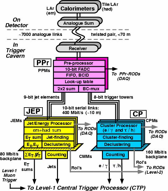
19 TRIGGER AND DATA ACQUISITION Fig. 16: ATLAS e/γ trigger algorithm Fig. 17: Overview of the ATLAS LVL1 calorimeter trigger 259
 to more than one crate.")
20 N. ELLIS The tower data from the PPr are transmitted to the cluster processor (CP). Note that the CP is implemented with very dense electronics so that there are only four crates in total. This minimizes the number of towers that need to be transmitted ( fanned out ) to more than one crate. Fan out is required for towers that contribute to windows for which the algorithmic processing is implemented in more than one crate. Also, within each CP crate, trigger-tower data need to be fanned out between electronic modules, and then between processing elements within each module. Considerations of connectivity and data-movement drive the design. In parallel with the CP, a jet/energy processor (JEP) searches for jet candidates and calculates missing-e T and scalar-e T sums. This is not described further here. A very important consideration in designing the LVL1 trigger is the need to identify uniquely the BC that produced the interaction of interest. This is not trivial, especially given that the calorimeter signals extend over many BCs. In order to assign observed energy deposits to a given BC, information has to be combined from a sequence of measurements. Figure 18 illustrates how this is done within the PPr (the logic is repeated ~ 7000 times so that this is done in parallel for all towers). The raw data for a given tower move along a pipeline that is clocked by the 40 MHz BC signal. The multipliers together with the adder tree implement a finite-impulse-response filter whose output is passed to a peak finder (a peak indicates that the energy was deposited in the BC currently being examined) and to a look-up table that converts the peak amplitude to an ET value. Special care is taken to avoid BC misidentification for very large pulses that may get distorted in the analogue electronics, since such signals could correspond to the most interesting events. The functionality shown in Fig. 18 is implemented in ASICs (four channels per ASIC). Fig. 18: Bunch-crossing identification The transmission of the data (i.e., the E T matrices) from the PPr to the CP is performed using a total of 5000 digital links each operating at 400 Mbits/s (each link carries data from two towers using a technique called BC multiplexing [6]). Where fan out is required, the corresponding links are duplicated 260

21 TRIGGER AND DATA ACQUISITION with the data being sent to two different CP crates. Within each CP crate, data are shared between neighbouring modules over a very high density crate back-plane (~ 800 pins per slot in a 9U crate; data rate of 160 Mbits/s per signal pin using point-to-point connections). On each of the modules, data are passed to eight large field-programmable gate arrays (FPGAs) that perform the algorithmic processing, fanning out signals to more than one FPGA where required. As an exercise, it is suggested that students make an order-of-magnitude estimate of the total bandwidth between the PPr and the CP, considering what this corresponds to in terms of an equivalent number of simultaneous telephone calls 6. The e/γ (together with the τ/h) algorithms are implemented using FPGAs. This has only become feasible thanks to recent advances in FPGA technology since very large and very fast devices are needed. Each FPGA handles an area of 4 2 windows, requiring data from 7 5 towers in each of the EM and hadronic calorimeters. The algorithm is described in a programming language (e.g., VHDL) that can be converted into the FPGA configuration file. This gives flexibility to adapt algorithms in the light of experience the FPGAs can be reconfigured in situ. Note that parameters of the algorithms can be changed easily and quickly, e.g., as the luminosity falls during the course of a coast of the beams in the LHC machine, since they are held in registers inside the FPGAs that can be modified at run time (i.e., there is no need to change the program in the FPGA). 11 High-level triggers and data acquisition at the LHC In the LHC experiments, data are transferred after a LVL1 trigger accept decision to large buffer memories in normal operation the subsequent stages should not introduce further dead-time. At this point in the readout chain, the data rates are still massive. An event size of ~ 1 Mbyte (after zero suppression or data compression) at ~ 100 khz event rate gives a total bandwidth of ~ 100 Gbytes/s (i.e., A~ 800 Gbits/s). This is far beyond the capacity of the bus-based event building of LEP. Such high data rates will be dealt with by using network-based event building and by only moving a subset of the data. Network-based event building is illustrated in Fig. 19 for the example of CMS. Data are stored in the readout systems until they have been transferred to the filter systems [associated with high-level trigger (HLT) processing], or until the event is rejected. Note that no node in the system sees the full data rate each readout system covers only a part of the detector and each filter system deals with only a fraction of the events. Fig. 19: CMS event builder 6 You may assume an order-of-magnitude data rate for voice calls of 10 kbits/s for example, the GSM mobile-phone standard uses a 9600 bit/s digital link to transmit the encoded voice signal. 261
22 N. ELLIS The LVL2 trigger decision can be made without accessing or processing all of the data. Substantial rejection can be made with respect to LVL1 without accessing the inner-tracking detectors calorimeter triggers can be refined using the full-precision, full-granularity calorimeter information; muon triggers can be refined using the high-precision readout from the muon detectors. It is therefore only necessary to access the inner-tracking data for the subset of events that pass this initial selection. ATLAS and CMS both use this sequential selection strategy. Nevertheless, the massive data rates pose problems even for network-based event building, and different solutions are being adopted in ATLAS and CMS to address this. In CMS the event building is factorized into a number of slices, each of which sees only a fraction of the total rate (see Fig. 20). This still requires a large total network bandwidth (which has implications for the cost), but it avoids the need for a very big central network switch. An additional advantage of this approach is that the size of the system can be scaled, starting with a few slices and adding more later (e.g., as additional funding becomes available). Eight slices: Each slice sees only 1/8 th of the events Fig. 20: The CMS slicing concept In ATLAS the amount of data to be moved is reduced by using the region-of-interest (RoI) mechanism (see Fig. 21). Here, the LVL1 trigger indicates the geographical location in the detector of candidate objects. LVL2 then only needs to access data from the RoIs, a small fraction of the total, even for the calorimeter and muon detectors that participated in the LVL1 selection. This requires relatively complicated mechanisms to serve the data selectively to the LVL2 trigger processors. In the example shown in Fig. 21, two muons are identified by LVL1. It can be seen that only a small fraction of the detector has to be accessed to validate the muons. In a first step only the data from the muon detectors are accessed and processed, and many events will be rejected where the more detailed analysis does not confirm the comparatively crude LVL1 selection (e.g., sharper p T cut). For those events that remain, the inner-tracker data will be accessed within the RoIs, allowing further rejection (e.g., of muons from decays in flight of charged pions and kaons). In a last step, calorimeter information may be accessed within the RoIs to select isolated muons (e.g., to reduce the high rate of events with muons from bottom and charm decays, while retaining those from W and Z decays). Concerning hardware implementation, the computer industry is putting on the market technologies that can be used to build much of the HLT/DAQ systems at LHC. Computer network products now offer high performance at affordable cost. Personal computers (PCs) provide exceptional value for money in processing power, with high-speed network interfaces as standard items. Nevertheless, custom hardware 262
23 TRIGGER AND DATA ACQUISITION Fig. 21: The ATLAS region-of-interest concept example of a dimuon event (see text) is needed in the parts of the system that see the full LVL1 trigger output rate (~ 100 khz). This concerns the readout systems that receive the detector data following a positive LVL1 trigger decision, and (in ATLAS) the interface to the LVL1 trigger that receives the RoI pointers. Of course, this is in addition to the specialized front-end electronics associated with the detectors that was discussed earlier (digitization, pipelines, derandomizers, etc.). As for the LVL1 trigger, the HLT has a trigger menu that describes which events should be selected. This is illustrated in Table 2 for the example of CMS, assuming a luminosity for early running of L ~ cm 2 s 1. The total rate of ~ 100 Hz contains a large fraction of events that are useful for physics analysis. Lower thresholds would be desirable, but the physics coverage has to be balanced against considerations of the offline computing cost. Note that there are large uncertainties on the rate calculations. Table 2: Estimated high-level trigger rates for L ~ cm 2 s 1 (CMS numbers from Ref. [7]) Trigger configuration One or more electrons with p T > 29 GeV, or two or more electrons with p T > 17 GeV One or more photons with p T > 80 GeV, or two or more photons with p T > 40, 25 GeV One or more muons with p T > 19 GeV, or two or more muons with p T > 7 GeV One or more taus with p T > 86 GeV, or two or more taus with p T > 59 GeV One or more jets with p T > 180 GeV and missing-e T > 123 GeV One or more jets with p T > 657 GeV, or three or more jets with p T > 247 GeV, or four or more jets with p T > 113 GeV Others (electron and jet, b-jets, etc.) Rate ~ 34 Hz ~ 9 Hz ~ 29 Hz ~ 4 Hz ~ 5 Hz ~ 9 Hz ~ 7 Hz 263
24 N. ELLIS A major challenge lies in the HLT/DAQ software. The event-selection algorithms for the HLT can be subdivided, at least logically, into LVL2 and LVL3 trigger stages. These might be performed by two separate processor systems (e.g., ATLAS), or in two distinct processing steps within the same processor system (e.g., CMS). The algorithms have to be supported by a software framework that manages the flow of data, supervising an event from when it arrives at the HLT/DAQ system until it is either rejected, or accepted and recorded on permanent storage. This includes software for efficient transfer of data to the algorithms. In addition to the above, there is a large amount of associated online software (run control, databases, book-keeping, etc.). 12 Case study Pierre Auger trigger The Pierre Auger detectors represent an interesting case for triggering. The detector is distributed over a very large area and a long time would be needed to transmit the signals to a central place. Highspeed data links would be expensive; and, of course, there is no cosmic bunch-crossing clock! The basic approach that is used is to have local triggering, independently for each detector unit (tank or fluorescence detector). A reasonably low-rate trigger is needed for each local unit, which must also be efficient for events of interest (i.e., very high energy cosmic rays). When a unit triggers, it sends its local trigger information to the central TDAQ system together with a precise time stamp. The central system then makes a selection combining all the information that is consistent with a common event time. For selected events, the full data are then collected from all of the relevant detector units. A final level of selection is then made based on a more detailed analysis of the full data. This approach can be illustrated by considering the Surface Detector (SD). Each tank unit, a photograph of which is shown in Fig. 22, contains three PMTs to detect Cherenkov light produced in the water, local TDAQ electronics, a local control computer, a radio link, and a solar power panel and battery. More details can be found in Ref. [17]. Each SD unit contains a two-level trigger system, data buffering, and a GPS-based time-stamp system (relative precision about 10 ns between units). Signals from the three PMTs in the unit are each digitized by 40 MHz ADCs. (By coincidence this is the same frequency as at the LHC.) The LVL1 trigger analyses the time profile of pulses and requires a coincidence between PMTs, with an output rate below 100 Hz per PMT. It uses programmable logic to implement pipelined trigger processing at 40 MHz. The LVL2 trigger refines the local selection and achieves an output rate less than 20 Hz per unit using software that runs on the local control processor. The local LVL2 trigger result is sent asynchronously to the central TDAQ over the radio link, while the full data are retained in the local buffer awaiting the LVL3 result. After receiving trigger information from an SD, the central TDAQ requests trigger information (with looser cuts) from other SD units. The LVL3 trigger combines data from both SD and Fluorescence Detector units. The final event rate depends on the size of the SD array that is active, but is sufficiently low to allow the data to be recorded for offline analysis. 13 Concluding remarks It is hoped that these lectures have succeeded in giving some insight into the challenges of building T/DAQ systems for HEP experiments. These include challenges connected with the physics (inventing algorithms that are fast, efficient for the physics of interest, and that give a large reduction in rate), and challenges in electronics and computing. It is also hoped that the lectures have demonstrated how the subject has evolved to meet the increasing demands, e.g., of LHC compared to LEP, by using new ideas based on new technologies. 264

25 TRIGGER AND DATA ACQUISITION Fig. 22: Photograph of a surface detector unit Acknowledgements The author would like to thank the local organizing committee and members of the Pierre Auger Collaboration for their wonderful hospitality during his stay in Argentina. In particular, he would like to thank Tere Dova who, as local director of the school, created such a wonderful atmosphere between all the participants, staff and students alike. The author would like to thank the following people for their help and advice in preparing the lectures and the present notes: Bob Blair, Helfried Burckhart, Vincenzo Canale, Philippe Charpentier, Eric Eisenhandler, Markus Elsing, Philippe Farthouat, John Harvey, Jim Linnerman, Claudio Luci, Wesley Smith and Alan Watson. Last, but not least, special thanks are due to Don Gauderio and his friends for all of the fun times we had together during the school. References [1] J. Schukraft, Heavy-ion physics at the LHC, in Proc CERN-CLAF School of Physics, CERN ALICE Collaboration, Trigger, Data Acquisition, High Level Trigger, Control System Technical Design Report, CERN-LHCC
Overview of the ATLAS Trigger/DAQ System
 Overview of the ATLAS Trigger/DAQ System A. J. Lankford UC Irvine May 4, 2007 This presentation is based very heavily upon a presentation made by Nick Ellis (CERN) at DESY in Dec 06. Nick Ellis, Seminar,
TRIGGER & DATA ACQUISITION. Nick Ellis PH Department, CERN, Geneva
 TRIGGER & DATA ACQUISITION Nick Ellis PH Department, CERN, Geneva 1 Lecture 1 2 LEVEL OF LECTURES Students at this School come from various backgrounds Phenomenology Analysis of physics data from experiments
First-level trigger systems at LHC. Nick Ellis EP Division, CERN, Geneva
 First-level trigger systems at LHC Nick Ellis EP Division, CERN, Geneva 1 Outline Requirements from physics and other perspectives General discussion of first-level trigger implementations Techniques and
Data acquisition and Trigger (with emphasis on LHC)
") Lecture 2 Data acquisition and Trigger (with emphasis on LHC) Introduction Data handling requirements for LHC Design issues: Architectures Front-end, event selection levels Trigger Future evolutions Conclusion
Lecture 2 Data acquisition and Trigger (with emphasis on LHC) Introduction Data handling requirements for LHC Design issues: Architectures Front-end, event selection levels Trigger Future evolutions Conclusion
Data acquisition and Trigger (with emphasis on LHC)
") Lecture 2! Introduction! Data handling requirements for LHC! Design issues: Architectures! Front-end, event selection levels! Trigger! Upgrades! Conclusion Data acquisition and Trigger (with emphasis on
Lecture 2! Introduction! Data handling requirements for LHC! Design issues: Architectures! Front-end, event selection levels! Trigger! Upgrades! Conclusion Data acquisition and Trigger (with emphasis on
LHC Experiments - Trigger, Data-taking and Computing
 Physik an höchstenergetischen Beschleunigern WS17/18 TUM S.Bethke, F. Simon V6: Trigger, data taking, computing 1 LHC Experiments - Trigger, Data-taking and Computing data rates physics signals ATLAS trigger
First-level trigger systems at LHC
 First-level trigger systems at LHC N. Ellis CERN, 1211 Geneva 23, Switzerland Nick.Ellis@cern.ch Abstract Some of the challenges of first-level trigger systems in the LHC experiments are discussed. The
Trigger and Data Acquisition at the Large Hadron Collider
 Trigger and Data Acquisition at the Large Hadron Collider Acknowledgments This overview talk would not exist without the help of many colleagues and all the material available online I wish to thank the
Data acquisi*on and Trigger - Trigger -
 Experimental Methods in Par3cle Physics (HS 2014) Data acquisi*on and Trigger - Trigger - Lea Caminada lea.caminada@physik.uzh.ch 1 Interlude: LHC opera3on Data rates at LHC Trigger overview Coincidence
Operation and Performance of the ATLAS Level-1 Calorimeter and Level-1 Topological Triggers in Run 2 at the LHC
 Operation and Performance of the ATLAS Level-1 Calorimeter and Level-1 Topological Triggers in Run 2 at the LHC Kirchhoff-Institute for Physics (DE) E-mail: sebastian.mario.weber@cern.ch ATL-DAQ-PROC-2017-026
LHCb Preshower(PS) and Scintillating Pad Detector (SPD): commissioning, calibration, and monitoring
 and Scintillating Pad Detector (SPD): commissioning, calibration, and monitoring") LHCb Preshower(PS) and Scintillating Pad Detector (SPD): commissioning, calibration, and monitoring Eduardo Picatoste Olloqui on behalf of the LHCb Collaboration Universitat de Barcelona, Facultat de Física,
LHCb Preshower(PS) and Scintillating Pad Detector (SPD): commissioning, calibration, and monitoring Eduardo Picatoste Olloqui on behalf of the LHCb Collaboration Universitat de Barcelona, Facultat de Física,
The Run-2 ATLAS. ATLAS Trigger System: Design, Performance and Plans
 The Run-2 ATLAS Trigger System: Design, Performance and Plans 14th Topical Seminar on Innovative Particle and Radiation Detectors October 3rd October 6st 2016, Siena Martin zur Nedden Humboldt-Universität
DAQ & Electronics for the CW Beam at Jefferson Lab
 DAQ & Electronics for the CW Beam at Jefferson Lab Benjamin Raydo EIC Detector Workshop @ Jefferson Lab June 4-5, 2010 High Event and Data Rates Goals for EIC Trigger Trigger must be able to handle high
The LHCb trigger system
 IL NUOVO CIMENTO Vol. 123 B, N. 3-4 Marzo-Aprile 2008 DOI 10.1393/ncb/i2008-10523-9 The LHCb trigger system D. Pinci( ) INFN, Sezione di Roma - Rome, Italy (ricevuto il 3 Giugno 2008; pubblicato online
ATLAS Muon Trigger and Readout Considerations. Yasuyuki Horii Nagoya University on Behalf of the ATLAS Muon Collaboration
 ATLAS Muon Trigger and Readout Considerations Yasuyuki Horii Nagoya University on Behalf of the ATLAS Muon Collaboration ECFA High Luminosity LHC Experiments Workshop - 2016 ATLAS Muon System Overview
arxiv: v2 [physics.ins-det] 13 Oct 2015
![arxiv: v2 [physics.ins-det] 13 Oct 2015](/thumbs/94/122335754.jpg "arxiv: v2 [physics.ins-det] 13 Oct 2015") Preprint typeset in JINST style - HYPER VERSION Level-1 pixel based tracking trigger algorithm for LHC upgrade arxiv:1506.08877v2 [physics.ins-det] 13 Oct 2015 Chang-Seong Moon and Aurore Savoy-Navarro
Preprint typeset in JINST style - HYPER VERSION Level-1 pixel based tracking trigger algorithm for LHC upgrade arxiv:1506.08877v2 [physics.ins-det] 13 Oct 2015 Chang-Seong Moon and Aurore Savoy-Navarro
Trigger and Data Acquisition Systems. Monika Wielers RAL. Lecture 3. Trigger. Trigger, Nov 2,
 Trigger and Data Acquisition Systems Monika Wielers RAL Lecture 3 Trigger Trigger, Nov 2, 2016 1 Reminder from last time Last time we learned how to build a data acquisition system Studied several examples
The Commissioning of the ATLAS Pixel Detector
 The Commissioning of the ATLAS Pixel Detector XCIV National Congress Italian Physical Society Genova, 22-27 Settembre 2008 Nicoletta Garelli Large Hadronic Collider MOTIVATION: Find Higgs Boson and New
PoS(EPS-HEP2017)476. The CMS Tracker upgrade for HL-LHC. Sudha Ahuja on behalf of the CMS Collaboration
476. The CMS Tracker upgrade for HL-LHC. Sudha Ahuja on behalf of the CMS Collaboration") UNESP - Universidade Estadual Paulista (BR) E-mail: sudha.ahuja@cern.ch he LHC machine is planning an upgrade program which will smoothly bring the luminosity to about 5 34 cm s in 228, to possibly reach
UNESP - Universidade Estadual Paulista (BR) E-mail: sudha.ahuja@cern.ch he LHC machine is planning an upgrade program which will smoothly bring the luminosity to about 5 34 cm s in 228, to possibly reach
Trigger and Data Acquisition (DAQ)
") Trigger and Data Acquisition (DAQ) Manfred Jeitler Institute of High Energy Physics (HEPHY) of the Austrian Academy of Sciences Level-1 Trigger of the CMS experiment LHC, CERN 1 contents aiming at a general
Trigger and Data Acquisition (DAQ) Manfred Jeitler Institute of High Energy Physics (HEPHY) of the Austrian Academy of Sciences Level-1 Trigger of the CMS experiment LHC, CERN 1 contents aiming at a general
8.882 LHC Physics. Detectors: Muons. [Lecture 11, March 11, 2009] Experimental Methods and Measurements
![8.882 LHC Physics. Detectors: Muons. [Lecture 11, March 11, 2009] Experimental Methods and Measurements](/thumbs/87/97059215.jpg "8.882 LHC Physics. Detectors: Muons. [Lecture 11, March 11, 2009] Experimental Methods and Measurements") 8.882 LHC Physics Experimental Methods and Measurements Detectors: Muons [Lecture 11, March 11, 2009] Organization Project 1 (charged track multiplicity) no one handed in so far... well deadline is tomorrow
8.882 LHC Physics Experimental Methods and Measurements Detectors: Muons [Lecture 11, March 11, 2009] Organization Project 1 (charged track multiplicity) no one handed in so far... well deadline is tomorrow
arxiv: v1 [hep-ex] 12 Nov 2010
![arxiv: v1 [hep-ex] 12 Nov 2010](/thumbs/75/71709828.jpg "arxiv: v1 [hep-ex] 12 Nov 2010") Trigger efficiencies at BES III N. Berger ;) K. Zhu ;2) Z.A. Liu D.P. Jin H. Xu W.X. Gong K. Wang G. F. Cao : Institute of High Energy Physics, Chinese Academy of Sciences, Beijing 49, China arxiv:.2825v
Trigger efficiencies at BES III N. Berger ;) K. Zhu ;2) Z.A. Liu D.P. Jin H. Xu W.X. Gong K. Wang G. F. Cao : Institute of High Energy Physics, Chinese Academy of Sciences, Beijing 49, China arxiv:.2825v
Track Triggers for ATLAS
 Track Triggers for ATLAS André Schöning University Heidelberg 10. Terascale Detector Workshop DESY 10.-13. April 2017 from https://www.enterprisedb.com/blog/3-ways-reduce-it-complexitydigital-transformation
Monika Wielers Rutherford Appleton Laboratory
 Lecture 2 Monika Wielers Rutherford Appleton Laboratory Trigger and Data Acquisition requirements for LHC Example: Data flow in ATLAS (transport of event information from collision to mass storage) 1 What
Attilio Andreazza INFN and Università di Milano for the ATLAS Collaboration The ATLAS Pixel Detector Efficiency Resolution Detector properties
 10 th International Conference on Large Scale Applications and Radiation Hardness of Semiconductor Detectors Offline calibration and performance of the ATLAS Pixel Detector Attilio Andreazza INFN and Università
The Compact Muon Solenoid Experiment. Conference Report. Mailing address: CMS CERN, CH-1211 GENEVA 23, Switzerland
 Available on CMS information server CMS CR -2017/349 The Compact Muon Solenoid Experiment Conference Report Mailing address: CMS CERN, CH-1211 GENEVA 23, Switzerland 09 October 2017 (v4, 10 October 2017)
The Liquid Argon Jet Trigger of the H1 Experiment at HERA. 1 Abstract. 2 Introduction. 3 Jet Trigger Algorithm
 The Liquid Argon Jet Trigger of the H1 Experiment at HERA Bob Olivier Max-Planck-Institut für Physik (Werner-Heisenberg-Institut) Föhringer Ring 6, D-80805 München, Germany 1 Abstract The Liquid Argon
Introduction to Trigger and Data Acquisition
 Introduction to Trigger and Data Acquisition Monika Wielers Rutherford Appleton Laboratory DAQ intro, Oct 20, 2015 1 What is it about... How to get from to DAQ intro, Oct 20, 2015 2 Or Main role of Trigger
The CMS electromagnetic calorimeter barrel upgrade for High-Luminosity LHC
 Journal of Physics: Conference Series OPEN ACCESS The CMS electromagnetic calorimeter barrel upgrade for High-Luminosity LHC To cite this article: Philippe Gras and the CMS collaboration 2015 J. Phys.:
Electronics, trigger and physics for LHC experiments
 Electronics, trigger and physics for LHC experiments 1 The Large hadron Collider 27 km length, 100 m underground, four interaction points (experiments) proton-proton collisions, 7 TeV + 7 TeV (14 TeV in
The CMS Muon Trigger
 The CMS Muon Trigger Outline: o CMS trigger system o Muon Lv-1 trigger o Drift-Tubes local trigger o peformance tests CMS Collaboration 1 CERN Large Hadron Collider start-up 2007 target luminosity 10^34
The LHCb Upgrade BEACH Simon Akar on behalf of the LHCb collaboration
 The LHCb Upgrade BEACH 2014 XI International Conference on Hyperons, Charm and Beauty Hadrons! University of Birmingham, UK 21-26 July 2014 Simon Akar on behalf of the LHCb collaboration Outline The LHCb
Field Programmable Gate Array (FPGA) for the Liquid Argon calorimeter back-end electronics in ATLAS
 for the Liquid Argon calorimeter back-end electronics in ATLAS") Field Programmable Gate Array (FPGA) for the Liquid Argon calorimeter back-end electronics in ATLAS Alessandra Camplani Università degli Studi di Milano The ATLAS experiment at LHC LHC stands for Large
Field Programmable Gate Array (FPGA) for the Liquid Argon calorimeter back-end electronics in ATLAS Alessandra Camplani Università degli Studi di Milano The ATLAS experiment at LHC LHC stands for Large
optimal hermeticity to reduce backgrounds in missing energy channels, especially to veto two-photon induced events.
 The TESLA Detector Klaus Mönig DESY-Zeuthen For the superconducting linear collider TESLA a multi purpose detector has been designed. This detector is optimised for the important physics processes expected
The ATLAS Trigger in Run 2: Design, Menu, and Performance
 he ALAS rigger in Run 2: Design, Menu, and Performance amara Vazquez Schroeder, on behalf of the ALAS Collaboration McGill University E-mail: tamara.vazquez.schroeder@cern.ch he ALAS trigger system is
LHCb Trigger System and selection for Bs->J/Ψ(ee)φ(KK)
φ(KK)") Krakow-Warsaw LHC Workshop November, 6, 2009 LHCb Trigger System and selection for Bs->J/Ψ(ee)φ(KK) Artur Ukleja on behalf of LHCb Warsaw Group Outline 1. Motivation 2. General scheme of LHCb trigger Two
Krakow-Warsaw LHC Workshop November, 6, 2009 LHCb Trigger System and selection for Bs->J/Ψ(ee)φ(KK) Artur Ukleja on behalf of LHCb Warsaw Group Outline 1. Motivation 2. General scheme of LHCb trigger Two
Upgrade of the ATLAS Thin Gap Chamber Electronics for HL-LHC. Yasuyuki Horii, Nagoya University, on Behalf of the ATLAS Muon Collaboration
 Upgrade of the ATLAS Thin Gap Chamber Electronics for HL-LHC Yasuyuki Horii, Nagoya University, on Behalf of the ATLAS Muon Collaboration TWEPP 2017, UC Santa Cruz, 12 Sep. 2017 ATLAS Muon System Overview
Performance of the ATLAS Muon Trigger in Run I and Upgrades for Run II
 Journal of Physics: Conference Series PAPER OPEN ACCESS Performance of the ALAS Muon rigger in Run I and Upgrades for Run II o cite this article: Dai Kobayashi and 25 J. Phys.: Conf. Ser. 664 926 Related
The design and performance of the ATLAS jet trigger
 th International Conference on Computing in High Energy and Nuclear Physics (CHEP) IOP Publishing Journal of Physics: Conference Series () doi:.88/7-696/// he design and performance of the ALAS jet trigger
PoS(LHCP2018)031. ATLAS Forward Proton Detector
031. ATLAS Forward Proton Detector") . Institut de Física d Altes Energies (IFAE) Barcelona Edifici CN UAB Campus, 08193 Bellaterra (Barcelona), Spain E-mail: cgrieco@ifae.es The purpose of the ATLAS Forward Proton (AFP) detector is to measure
. Institut de Física d Altes Energies (IFAE) Barcelona Edifici CN UAB Campus, 08193 Bellaterra (Barcelona), Spain E-mail: cgrieco@ifae.es The purpose of the ATLAS Forward Proton (AFP) detector is to measure
Layout and prototyping of the new ATLAS Inner Tracker for the High Luminosity LHC
 Layout and prototyping of the new ATLAS Inner Tracker for the High Luminosity LHC Ankush Mitra, University of Warwick, UK on behalf of the ATLAS ITk Collaboration PSD11 : The 11th International Conference
The Run-2 ATLAS Trigger System
 he Run-2 ALAS rigger System Arantxa Ruiz Martínez on behalf of the ALAS Collaboration Department of Physics, Carleton University, Ottawa, ON, Canada E-mail: aranzazu.ruiz.martinez@cern.ch Abstract. he
What do the experiments want?
 What do the experiments want? prepared by N. Hessey, J. Nash, M.Nessi, W.Rieger, W. Witzeling LHC Performance Workshop, Session 9 -Chamonix 2010 slhcas a luminosity upgrade The physics potential will be
Installation, Commissioning and Performance of the CMS Electromagnetic Calorimeter (ECAL) Electronics
 Electronics") Installation, Commissioning and Performance of the CMS Electromagnetic Calorimeter (ECAL) Electronics How to compose a very very large jigsaw-puzzle CMS ECAL Sept. 17th, 2008 Nicolo Cartiglia, INFN, Turin,
Installation, Commissioning and Performance of the CMS Electromagnetic Calorimeter (ECAL) Electronics How to compose a very very large jigsaw-puzzle CMS ECAL Sept. 17th, 2008 Nicolo Cartiglia, INFN, Turin,
Status of the LHCb Experiment
 Status of the LHCb Experiment Werner Witzeling CERN, Geneva, Switzerland On behalf of the LHCb Collaboration Introduction The LHCb experiment aims to investigate CP violation in the B meson decays at LHC
Micromegas calorimetry R&D
 Micromegas calorimetry R&D June 1, 214 The Micromegas R&D pursued at LAPP is primarily intended for Particle Flow calorimetry at future linear colliders. It focuses on hadron calorimetry with large-area
Trigger and DAQ at the LHC. (Part II)
") Trigger and DAQ at the LHC (Part II) Tulika Bose Brown University NEPPSR 2007 August 16, 2007 1 The LHC Trigger Challenge σ mb μb nb pb fb σ inelastic bb W Z t t OBSERVED gg H SM qq qqh SM H SM γγ h γγ
Trigger and DAQ at the LHC (Part II) Tulika Bose Brown University NEPPSR 2007 August 16, 2007 1 The LHC Trigger Challenge σ mb μb nb pb fb σ inelastic bb W Z t t OBSERVED gg H SM qq qqh SM H SM γγ h γγ
Level-1 Calorimeter Trigger Calibration
 December 2004 Level-1 Calorimeter Trigger Calibration Birmingham, Heidelberg, Mainz, Queen Mary, RAL, Stockholm Alan Watson, University of Birmingham Norman Gee, Rutherford Appleton Lab Outline Reminder
Triggers For LHC Physics
 Triggers For LHC Physics Bryan Dahmes University of Minnesota bryan.michael.dahmes@cern.ch 1 Introduction Some terminology Motivation: Why do we need a trigger? Explanation of the Trigger components Level
Data Acquisition System for the Angra Project
 Angra Neutrino Project AngraNote 012-2009 (Draft) Data Acquisition System for the Angra Project H. P. Lima Jr, A. F. Barbosa, R. G. Gama Centro Brasileiro de Pesquisas Físicas - CBPF L. F. G. Gonzalez
3.1 Introduction, design of HERA B
 3. THE HERA B EXPERIMENT In this chapter we discuss the setup of the HERA B experiment. We start with an introduction on the design of HERA B (section 3.1) and a short description of the accelerator (section
CMS SLHC Tracker Upgrade: Selected Thoughts, Challenges and Strategies
 : Selected Thoughts, Challenges and Strategies CERN Geneva, Switzerland E-mail: marcello.mannelli@cern.ch Upgrading the CMS Tracker for the SLHC presents many challenges, of which the much harsher radiation
Signal Reconstruction of the ATLAS Hadronic Tile Calorimeter: implementation and performance
 Signal Reconstruction of the ATLAS Hadronic Tile Calorimeter: implementation and performance G. Usai (on behalf of the ATLAS Tile Calorimeter group) University of Texas at Arlington E-mail: giulio.usai@cern.ch
The Compact Muon Solenoid Experiment. Conference Report. Mailing address: CMS CERN, CH-1211 GENEVA 23, Switzerland
 Available on CMS information server CMS CR -2015/213 The Compact Muon Solenoid Experiment Conference Report Mailing address: CMS CERN, CH-1211 GENEVA 23, Switzerland 05 October 2015 (v2, 12 October 2015)
Expected Performance of the ATLAS Inner Tracker at the High-Luminosity LHC
 Expected Performance of the ATLAS Inner Tracker at the High-Luminosity LHC Noemi Calace noemi.calace@cern.ch On behalf of the ATLAS Collaboration 25th International Workshop on Deep Inelastic Scattering
The Status of ATLAS. Xin Wu, University of Geneva On behalf of the ATLAS collaboration. X. Wu, HCP2009, Evian, 17/11/09 ATL-GEN-SLIDE
 ATL-GEN-SLIDE-2009-356 18 November 2009 The Status of ATLAS Xin Wu, University of Geneva On behalf of the ATLAS collaboration 1 ATLAS and the people who built it 25m high, 44m long Total weight 7000 tons
LHCb Trigger & DAQ Design technology and performance. Mika Vesterinen ECFA High Luminosity LHC Experiments Workshop 8/10/2016
 LHCb Trigger & DAQ Design technology and performance Mika Vesterinen ECFA High Luminosity LHC Experiments Workshop 8/10/2016 2 Introduction The LHCb upgrade will allow 5x higher luminosity and with greatly
EPJ C direct. The ATLAS trigger system. 1 Introduction. 2 The ATLAS experiment. electronic only. R. Hauser, on behalf of the ATLAS collaboration
 Eur Phys J C 34, s01, s173 s183 (2004) Digital Object Identifier (DOI) 10.1140/epjcd/s2004-04-018-6 EPJ C direct electronic only The ATLAS trigger system R. Hauser, on behalf of the ATLAS collaboration
US CMS Calorimeter. Regional Trigger System WBS 3.1.2
 WBS Dictionary/Basis of Estimate Documentation US CMS Calorimeter Regional Trigger System WBS 3.1.2-1- 1. INTRODUCTION 1.1 The CMS Calorimeter Trigger System The CMS trigger and data acquisition system
Hardware Trigger Processor for the MDT System
 University of Massachusetts Amherst E-mail: tcpaiva@cern.ch We are developing a low-latency hardware trigger processor for the Monitored Drift Tube system for the Muon Spectrometer of the ATLAS Experiment.
CMS Note Mailing address: CMS CERN, CH-1211 GENEVA 23, Switzerland
 Available on CMS information server CMS NOTE 1997/084 The Compact Muon Solenoid Experiment CMS Note Mailing address: CMS CERN, CH-1211 GENEVA 23, Switzerland 29 August 1997 Muon Track Reconstruction Efficiency
The LHCb trigger system: performance and outlook
 : performance and outlook Scuola Normale Superiore and INFN Pisa E-mail: simone.stracka@cern.ch The LHCb experiment is a spectrometer dedicated to the study of heavy flavor at the LHC. The rate of proton-proton
MuLan Experiment Progress Report
 BV 37 PSI February 16 2006 p. 1 MuLan Experiment Progress Report PSI Experiment R 99-07 Françoise Mulhauser, University of Illinois at Urbana Champaign (USA) The MuLan Collaboration: BERKELEY BOSTON ILLINOIS
Beam Condition Monitors and a Luminometer Based on Diamond Sensors
 Beam Condition Monitors and a Luminometer Based on Diamond Sensors Wolfgang Lange, DESY Zeuthen and CMS BRIL group Beam Condition Monitors and a Luminometer Based on Diamond Sensors INSTR14 in Novosibirsk,
Mitigating high energy anomalous signals in the CMS barrel Electromagnetic Calorimeter
 Mitigating high energy anomalous signals in the CMS barrel Electromagnetic Calorimeter Summary report Ali Farzanehfar University of Southampton University of Southampton Spike mitigation May 28, 2015 1
arxiv: v1 [physics.ins-det] 25 Oct 2012
![arxiv: v1 [physics.ins-det] 25 Oct 2012](/thumbs/93/113010072.jpg "arxiv: v1 [physics.ins-det] 25 Oct 2012") The RPC-based proposal for the ATLAS forward muon trigger upgrade in view of super-lhc arxiv:1210.6728v1 [physics.ins-det] 25 Oct 2012 University of Michigan, Ann Arbor, MI, 48109 On behalf of the ATLAS
The RPC-based proposal for the ATLAS forward muon trigger upgrade in view of super-lhc arxiv:1210.6728v1 [physics.ins-det] 25 Oct 2012 University of Michigan, Ann Arbor, MI, 48109 On behalf of the ATLAS
1.1 The Muon Veto Detector (MUV)
") 1.1 The Muon Veto Detector (MUV) 1.1 The Muon Veto Detector (MUV) 1.1.1 Introduction 1.1.1.1 Physics Requirements and General Layout In addition to the straw chambers and the RICH detector, further muon
1.1 The Muon Veto Detector (MUV) 1.1 The Muon Veto Detector (MUV) 1.1.1 Introduction 1.1.1.1 Physics Requirements and General Layout In addition to the straw chambers and the RICH detector, further muon
Phase 1 upgrade of the CMS pixel detector
 Phase 1 upgrade of the CMS pixel detector, INFN & University of Perugia, On behalf of the CMS Collaboration. IPRD conference, Siena, Italy. Oct 05, 2016 1 Outline The performance of the present CMS pixel
Testing the Electronics for the MicroBooNE Light Collection System
 Testing the Electronics for the MicroBooNE Light Collection System Kathleen V. Tatem Nevis Labs, Columbia University & Fermi National Accelerator Laboratory August 3, 2012 Abstract This paper discusses
Real-time flavour tagging selection in ATLAS. Lidija Živković, Insttut of Physics, Belgrade
 Real-time flavour tagging selection in ATLAS Lidija Živković, Insttut of Physics, Belgrade On behalf of the collaboration Outline Motivation Overview of the trigger b-jet trigger in Run 2 Future Fast TracKer
Development of a Highly Selective First-Level Muon Trigger for ATLAS at HL-LHC Exploiting Precision Muon Drift-Tube Data
 Development of a Highly Selective First-Level Muon Trigger for ATLAS at HL-LHC Exploiting Precision Muon Drift-Tube Data S. Abovyan, V. Danielyan, M. Fras, P. Gadow, O. Kortner, S. Kortner, H. Kroha, F.
9. TRIGGER AND DATA ACQUISITION
 9. TRIGGER AND DATA ACQUISITION 9.1 INTRODUCTION The CMS trigger and data acquisition system is shown in Fig. 9.1 and the used terminology in Table 9.1. For the nominal LHC design luminosity of 1 34 cm
`First ep events in the Zeus micro vertex detector in 2002`
 Amsterdam 18 dec 2002 `First ep events in the Zeus micro vertex detector in 2002` Erik Maddox, Zeus group 1 History (1): HERA I (1992-2000) Lumi: 117 pb -1 e +, 17 pb -1 e - Upgrade (2001) HERA II (2001-2006)
Silicon W Calorimeters for the PHENIX Forward Upgrade
 E.Kistenev Silicon W Calorimeters for the PHENIX Forward Upgrade Event characterization detectors in middle PHENIX today Two central arms for measuring hadrons, photons and electrons Two forward arms for
Hardware Trigger Processor for the MDT System
 University of Massachusetts Amherst E-mail: tcpaiva@cern.ch We are developing a low-latency hardware trigger processor for the Monitored Drift Tube system in the Muon spectrometer. The processor will fit
The Trigger System of the MEG Experiment
 The Trigger System of the MEG Experiment On behalf of D. Nicolò F. Morsani S. Galeotti M. Grassi Marco Grassi INFN - Pisa Lecce - 23 Sep. 2003 1 COBRA magnet Background Rate Evaluation Drift Chambers Target
The Compact Muon Solenoid Experiment. Conference Report. Mailing address: CMS CERN, CH-1211 GENEVA 23, Switzerland. CMS detector performance.
 Available on CMS information server CMS CR -2017/412 The Compact Muon Solenoid Experiment Conference Report Mailing address: CMS CERN, CH-1211 GENEVA 23, Switzerland 08 November 2017 (v3, 17 November 2017)
Muon Collider background rejection in ILCroot Si VXD and Tracker detectors
 Muon Collider background rejection in ILCroot Si VXD and Tracker detectors N. Terentiev (Carnegie Mellon U./Fermilab) MAP 2014 Winter Collaboration Meeting Dec. 3-7, 2014 SLAC New MARS 1.5 TeV Muon Collider
The trigger system of the muon spectrometer of the ALICE experiment at the LHC
 The trigger system of the muon spectrometer of the ALICE experiment at the LHC Francesco Bossù for the ALICE collaboration University and INFN of Turin Siena, 09 June 2010 Outline 1 Introduction 2 Muon
ATLAS ITk and new pixel sensors technologies
 IL NUOVO CIMENTO 39 C (2016) 258 DOI 10.1393/ncc/i2016-16258-1 Colloquia: IFAE 2015 ATLAS ITk and new pixel sensors technologies A. Gaudiello INFN, Sezione di Genova and Dipartimento di Fisica, Università
Measurement of the charged particle density with the ATLAS detector: First data at vs = 0.9, 2.36 and 7 TeV Kayl, M.S.
 UvA-DARE (Digital Academic Repository) Measurement of the charged particle density with the ATLAS detector: First data at vs = 0.9, 2.36 and 7 TeV Kayl, M.S. Link to publication Citation for published
Trigger Overview. Wesley Smith, U. Wisconsin CMS Trigger Project Manager. DOE/NSF Review April 12, 2000
 Overview Wesley Smith, U. Wisconsin CMS Project Manager DOE/NSF Review April 12, 2000 1 TriDAS Main Parameters Level 1 Detector Frontend Readout Systems Event Manager Builder Networks Run Control System
Test Beam Measurements for the Upgrade of the CMS Phase I Pixel Detector
 Test Beam Measurements for the Upgrade of the CMS Phase I Pixel Detector Simon Spannagel on behalf of the CMS Collaboration 4th Beam Telescopes and Test Beams Workshop February 4, 2016, Paris/Orsay, France
PoS(Vertex 2007)034. Tracking in the trigger: from the CDF experience to CMS upgrade. Fabrizio Palla 1. Giuliano Parrini
034. Tracking in the trigger: from the CDF experience to CMS upgrade. Fabrizio Palla 1. Giuliano Parrini") Tracking in the trigger: from the CDF experience to CMS upgrade 1 INFN Pisa Largo B. Pontecorvo 3, 56127 Pisa, Italy E-mail:Fabrizio.Palla@cern.ch Giuliano Parrini University and INFN Florence Via G. Sansone
Tracking in the trigger: from the CDF experience to CMS upgrade 1 INFN Pisa Largo B. Pontecorvo 3, 56127 Pisa, Italy E-mail:Fabrizio.Palla@cern.ch Giuliano Parrini University and INFN Florence Via G. Sansone
Instructions for gg Coincidence with 22 Na. Overview of the Experiment
 Overview of the Experiment Instructions for gg Coincidence with 22 Na 22 Na is a radioactive element that decays by converting a proton into a neutron: about 90% of the time through β + decay and about
Upgrade tracking with the UT Hits
 LHCb-PUB-2014-004 (v4) May 20, 2014 Upgrade tracking with the UT Hits P. Gandini 1, C. Hadjivasiliou 1, J. Wang 1 1 Syracuse University, USA LHCb-PUB-2014-004 20/05/2014 Abstract The performance of the
A Prototype Amplifier-Discriminator Chip for the GLAST Silicon-Strip Tracker
 A Prototype Amplifier-Discriminator Chip for the GLAST Silicon-Strip Tracker Robert P. Johnson Pavel Poplevin Hartmut Sadrozinski Ned Spencer Santa Cruz Institute for Particle Physics The GLAST Project
VELO: the LHCb Vertex Detector
 LHCb note 2002-026 VELO VELO: the LHCb Vertex Detector J. Libby on behalf of the LHCb collaboration CERN, Meyrin, Geneva 23, CH-1211, Switzerland Abstract The Vertex Locator (VELO) of the LHCb experiment
The CMS Silicon Strip Tracker and its Electronic Readout
 The CMS Silicon Strip Tracker and its Electronic Readout Markus Friedl Dissertation May 2001 M. Friedl The CMS Silicon Strip Tracker and its Electronic Readout 2 Introduction LHC Large Hadron Collider:
BaBar and PEP II. Physics
 BaBar and PEP II BaBar SVT DCH DIRC ECAL IFR Trigger Carsten Hast LAL Orsay December 8th 2000 Physics Main Goal: CP Violation sin2β,sin2α PEP II Performance Backgrounds December 8th 2000 Carsten Hast PEP
Totem Experiment Status Report
 Totem Experiment Status Report Edoardo Bossini (on behalf of the TOTEM collaboration) 131 st LHCC meeting 1 Outline CT-PPS layout and acceptance Running operation Detector commissioning CT-PPS analysis
Study of the ALICE Time of Flight Readout System - AFRO
 Study of the ALICE Time of Flight Readout System - AFRO Abstract The ALICE Time of Flight Detector system comprises about 176.000 channels and covers an area of more than 100 m 2. The timing resolution
Calorimetry in particle physics experiments
 Calorimetry in particle physics experiments Unit n. 7 Front End and Trigger electronics Roberta Arcidiacono Lecture overview Signal processing Some info on calorimeter FE Pre-amplifiers Charge sensitive
The High-Voltage Monolithic Active Pixel Sensor for the Mu3e Experiment
 The High-Voltage Monolithic Active Pixel Sensor for the Mu3e Experiment Shruti Shrestha On Behalf of the Mu3e Collaboration International Conference on Technology and Instrumentation in Particle Physics
Diamond sensors as beam conditions monitors in CMS and LHC
 Diamond sensors as beam conditions monitors in CMS and LHC Maria Hempel DESY Zeuthen & BTU Cottbus on behalf of the BRM-CMS and CMS-DESY groups GSI Darmstadt, 11th - 13th December 2011 Outline 1. Description
Contents. Why waveform? Waveform digitizer : Domino Ring Sampler CEX Beam test autumn 04. Summary
 Contents Why waveform? Waveform digitizer : Domino Ring Sampler CEX Beam test data @PSI autumn 04 Templates and time resolution Pulse Shape Discrimination Pile-up rejection Summary 2 In the MEG experiment
HF Upgrade Studies: Characterization of Photo-Multiplier Tubes
 HF Upgrade Studies: Characterization of Photo-Multiplier Tubes 1. Introduction Photomultiplier tubes (PMTs) are very sensitive light detectors which are commonly used in high energy physics experiments.
The 1st Result of Global Commissioning of the ATALS Endcap Muon Trigger System in ATLAS Cavern
 The 1st Result of Global Commissioning of the ATALS Endcap Muon Trigger System in ATLAS Cavern Takuya SUGIMOTO (Nagoya University) On behalf of TGC Group ~ Contents ~ 1. ATLAS Level1 Trigger 2. Endcap
RP220 Trigger update & issues after the new baseline
 RP220 Trigger update & issues after the new baseline By P. Le Dû pledu@cea.fr Cracow - P. Le Dû 1 New layout features Consequence of the meeting with RP420 in Paris last September Add 2 vertical detection
Pixel hybrid photon detectors
 Pixel hybrid photon detectors for the LHCb-RICH system Ken Wyllie On behalf of the LHCb-RICH group CERN, Geneva, Switzerland 1 Outline of the talk Introduction The LHCb detector The RICH 2 counter Overall