Engineering Drawing System
|
|
|
- Marcia York
- 5 years ago
- Views:
Transcription
1 LPR Effective Date: July 18, 2004 Expiration Date: July 18, 2008 Langley Research Center Engineering Drawing System National Aeronautics and Space Administration
2 Responsible Office: Systems Engineering Competency P.1 PURPOSE PREFACE The engineering drawing practices and procedures set forth in this directive are based on established Government-industry standards, supplemented where necessary by a minimum of requirements peculiar to the NASA Langley Research Center. The purpose of this directive is to provide a uniform but flexible system of drawing preparation, use, and interpretation. A standard drawing numbering system, Engineering Drawing Files (EDF), and drawing and documentation control system are included. This directive will be maintained by the Engineering Drawing System Committee with representatives from selected organizations. P.2 APPLICABILITY This directive is applicable to all engineering drawings generated by LaRC personnel and their supporting service contractors. P.3 AUTHORITY ASME-Y14.100, DOD Standard Practice for Engineering Drawings P.4 REFERENCES The standards listed below, in addition to those listed in ASME-Y14.100, are requirements for generating engineering drawings: MIL-STD-403, Preparation for and Installation of Rivets and Screws, Rockets, and Missile Structures USAS B , Preferred Limits and Fits for Cylindrical Parts NAS 523, Fastener Code AWS A , Metric Practice Guide for the Welding Industry AWS A , Symbols for Welding and Non-Destructive Testing Unless identified by date, the edition including addenda and code cases in effect at the start of the design, shall apply. i
3 NPR , Security Procedures and Guidelines LPR , Facility System Safety Analysis and Configuration Management LPR , Space Product Assurance" Langley Form 33, Preparation of Drawing Record Card P.5 CANCELLATION This LPR cancels LAPG dated March 7, original signed on file Douglas L. Dwoyer Associate Director for R&T Competencies ii
4 TABLE OF CONTENTS 1 ADMINISTRATIVE PROCEDURES Scope Maintenance of Engineering Drawing Directive Engineering Drawing Files Drawing Numbering System Preparation of Drawing Record Card, NASA Langley Form Submittal of Drawings to EDF Verification of Drawings Microfilming Distribution of Aperture Cards Filing of Drawings and Drawing Record Card Retrieval and Return of Previously Filed Drawings Drawing Changes Drawing Revisions Document Change Notice (DCN) Drawing Cancellation Procedure Security Classification ENGINEERING DRAWING REQUIREMENTS Size and Format Drawing Sizes Basic Sheet Format Title Block Drawing Titles Numbering of Drawings and Parts Auxiliary Blocks Drawing Notes CAGE CODE Basic Requirements Purpose of Drawings Legibility Mechanical and Photographic Processes General Drawing Practice Dimensions and Tolerances DRAWING AND DOCUMENTATION CONTROL Definition iii
5 3.2 Applicability Drawing Media Types Release Approval Approval Process Type 1 Drawings Type 2 Drawings Type 3 Drawings iv
6 1 ADMINISTRATIVE PROCEDURES 1.1 Scope The Engineering Drawing System Procedural Requirement establishes the procedural requirements and practices to be followed in the preparation, maintenance, control, and utilization of engineering drawings. It applies to all engineering drawings generated by Langley Research Center (LaRC) personnel and their supporting services contractors. An engineering drawing is defined as a document, which discloses by means of pictorial and/or textual presentations, the form and function of an item, is assigned an LaRC drawing number, and contains proper approvals. This procedural requirement is not applicable to any sketches, diagrams, informal schematics, or other instructions. This procedural requirement is authorized for use in establishing engineering drawing format and procedures for all research, design, development, fabrication, and installation activities. 1.2 Maintenance of Engineering Drawing Directive The Director of the Systems Engineering Competency has the functional responsibility for the basic procedural requirement and its approval, application, and implementation. The Engineering Drawing System Committee (EDSC) will have the responsibility for making revisions or adding supplements to the procedural requirement. The committee will consist of the following: Discipline Area Number of Representatives Flight Design Engineer 2 Facility Design Engineer, 2 Model Design Engineer 1 EDF COTR 1 Engineering Drawing Files 1 The Director of the Systems Engineering Competency appoints the Chairperson. LAPD , Boards, Panels, Committees, Councils, and Teams.) (See Requests for revisions or supplements to the procedural requirement shall be addressed to the committee chairperson. Supplements and revisions will be posted on the NASA Langley Management System web site. 1
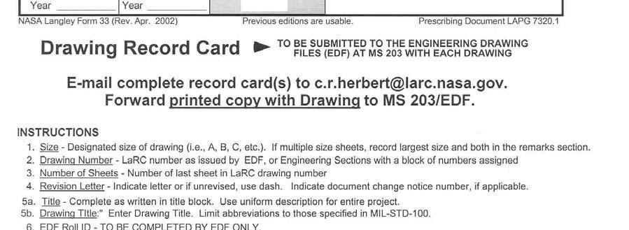
7 1.3 Engineering Drawing Files The Engineering Drawing Files (EDF) office, is responsible for assigning drawing numbers, preparing documents for micro-filming, publishing an index, and filing drawings, aperture cards, and X-rays Drawing Numbering System A using organization may request initial assignment of drawing numbers by telephone or letter to EDF. The EDF clerk shall enter all available information on the log including the type of drawing, revision letter, title, size, organization code, name of requester, date assigned, and notify the requester of the assigned drawing number(s). A block of numbers may be issued to organizations as required Preparation of Drawing Record Card, NASA Langley Form 33 Upon completion of the new or revised drawing, the originator shall prepare Langley Form 33, Drawing Record Card (Electronic form obtained from Informed Filler), by entering data listed in the Langley Form 33 instructions. 2


8 3
9 1.3.3 Submittal of Drawings to EDF After the initial release of prints by the originating organization s approving official, the originator shall remove the Section copy (1) of Langley Form 33, attach the EDF copy (2) to the drawing, and forward drawing and Langley Form 33 to EDF. If using the electronic version of the Langley Form 33, the originator shall print a copy of the Langley Form 33 to attach to the drawing to be filed, and the originator shall a copy to EDF as per the instructions on the electronic form Verification of Drawings The EDF clerk shall check the drawing for the following: a. Drawing submittal All incoming drawings shall be routed through the EDF receiving area for processing. The clerk shall determine if the drawings are being submitted for the first time or if they are previously filed drawings being returned to EDF. New and revised drawings are to be processed and made ready for microfilming. For drawings, which have not been revised, the clerk shall log in the date returned on the Langley Form 33, and return the drawing to the files. b. Valid drawing number The drawing number shall be checked for duplication. EDF shall notify and return the drawing to the originating organization if required. c. LaRC administrative standards Drawings must meet LaRC requirements, with the correctly assigned drawing numbers, properly assigned revision letter, and properly identified configurations (see ASME-Y14.100). The drawing shall be returned to originator if incorrect. When the drawing is verified, the EDF clerk shall stamp FILE on the drawing and process for microfilming Microfilming The EDF clerk shall prepare the drawing for microfilming. When microfilming is complete, Micrographics shall return the drawing and mounted aperture cards to EDF Distribution of Aperture Cards Three silver halide original aperture cards are produced and distributed as follows: a. Security File - This file has a copy of all revisions submitted to EDF. b. EDF Working File - Latest revision of drawing is maintained in EDF. c. Engineering Copy - Organization identified on Langley Form 33 shall receive aperture card if requested. If mail stop changes, please notify EDF. 4
10 1.3.7 Filing of Drawings and Drawing Record Card The drawings shall be indexed by size and drawing number and placed in files. Information obtained on Langley Form 33 shall be indexed into the computer. EDF copy (2) or the electronic printed copy shall be filed in a card file in drawing number sequence Retrieval and Return of Previously Filed Drawings The EDF clerk will sign and date EDF copy (2) of Langley Form 33 or the electronic printed copy with name and organization of the individual obtaining the original drawing. The card will be filed in drawing number sequence until the drawing is returned. If the original drawing is under configuration control, it cannot be removed from EDF without proper authority. When the revised drawing is returned to EDF, the EDF clerk takes the same actions as for the original drawing as stated in paragraph On multisheet drawings, revisions must be indicated on the first sheet and each affected sheet of the drawing or the entire drawing will be rejected by EDF. 1.4 Drawing Changes Changes to the engineering drawings must be made by one of two methods: a. Drawing revision b. Document Change Notice (DCN) Excluding facility drawings. All changes made after formal release of drawings must be authorized in the same manner and processed through EDF for recording and microfilming. It is the responsibility of the design activity to assure, that changes and revisions to engineering drawings do not violate configuration control documents (CCD s) Drawing Revisions The procedures described in ASME-Y apply to LaRC generated drawings. Original drawings or other reproducibles may be withdrawn from EDF for revision and are to be returned to EDF. Revision blocks will be filled out as illustrated in Figure 1. The zone column is optional but helpful in locating the change. 5
11 ZONE LTR DESCRIPTION DATE APPROVAL E9 A MATERIAL WAS QQ-S-633 FOR.-001 PART INCORPORATES DCN NO Jan John Doe E9 B3 B (1) WAS 1.12, (2) ADDED 1.85,(3) ADDED TERMINAL TO PT. 9, (4) DELETED C2, (5) RELOCATED POSTS AND TAPPED HOLES DELINEATION, (6) DELETED NOTE: TEST IN ACCORDANCE WITH A Document Change Notice (DCN) Feb Figure 1. Sample Revision Block John Doe A DCN is an interim method of changing the information contained on an engineering drawing or associated document. Such changes are to be incorporated into the drawing by formal revision unless otherwise specified on the DCN. DCN s will remain active until incorporated by revision and so noted in the revision block. The incorporated DCN shall then be retired to the historical files. Not more than three DCN s may be outstanding against any one drawing at any one time. 1.5 Drawing Cancellation Procedure Drawing cancellation will be done in accordance with ASME-Y Security Classification DD Form 254, DOD Contract Security Classification Specification, prepared in accordance with DOD M, Industrial Security Manual for Safeguarding Classified Information, shall be used by LaRC to provide specific security classification guidance to contractors who originate drawings. Specific classification and marking guidance shall be provided by the LaRC Security Classification Officer for drawings originated by NASA, LaRC. The classification of the drawings shall be determined by an appropriate security classification guide or other source document and marked in accordance with NPR , Security Procedures and Guidelines. 6
12 2 ENGINEERING DRAWING REQUIREMENTS 2.1 Size and Format Drawing Sizes Finished sheet format sizes and the size-designated letter are those listed in ASME-Y (ASME Y14.1). Multiple sheet drawings are permissible Basic Sheet Format The general format and arrangement of data on drawings shall be in accordance with ASME-Y (ASME Y14.1). An alternate basic sheet is authorized for facility drawings of D size only and is shown below. 7
13 2.1.3 Title Block The basic drawing title block in the lower right-hand corner of each drawing shall be in accordance with ASME-Y (ASME Y14.1). An alternate title block is authorized for use with facility drawings of D size only Drawing Titles Drawing titles shall conform to the procedures for creating title block nomenclature entries for drawings and for parts detailed thereon as specified in ASME-Y (ASME Y14.1) Numbering of Drawings and Parts The LaRC standard numbering system provides for a seven-digit (maximum) drawing number, centrally controlled and issued by the Engineering Drawing Files, a three-digit (maximum) dash number identifier for parts, subassemblies, assemblies, or configurations of assemblies as determined by the design activity, and a revision letter. The desired method of marking and identification of parts must be specified on the drawing and shall conform to LPR , Space Product Assurance." X Revision letter (or if no revision) Part, assembly, or configuration identifier Drawing number Auxiliary Blocks Auxiliary blocks are authorized as set forth in ASME-Y Drawing Notes Drawing notes shall be in accordance with ASME-Y CAGE CODE The official CAGE CODE Number for NASA LaRC is This number shall be reflected in the Drawing Title Block under the CAGE CODE entry block. 8
14 2.2 Basic Requirements Purpose of Drawings The purpose of drawings is to convey sufficient engineering requirements, characteristics, and information to manufacture or procure an item or to procure materials or services. Drawings shall be complete for the purpose intended. Good drafting technique is essential; however, drawings have no artistic value and drafting technique is not an end in itself. A good drawing is one, which can be easily and completely understood by craftsmen, production planners, buyers, and others who must use the drawing Legibility LaRC regulations require the microfilming of all drawings and associated data. Each drawing must be clear enough for legible microfilm copy, as specified in ASME-Y All line-work shall be sharply defined and of uniform density. Lettering shall be clear and adequately spaced. All line-work and lettering shall be sufficiently opaque to be legible in full size copies prepared by any generally accepted method of reproduction Mechanical and Photographic Processes Mechanical and photographic processes may be used to reduce preparation time. Printed material shall be typewritten in lieu of hand lettering, whenever possible. When making new drawings, which are similar to existing drawings, use photographic or other reproduction techniques to obtain a permanent, reproducible copy of the existing drawings and then revise to produce the new drawings, which shall be renumbered and released as a new drawing. When a number of drawings or sheets of a drawing are required, which are similar in most respects, draw one sheet containing all common data, print permanent reproducibles, then add the remaining data to each General Drawing Practice General drawing practice shall be in accordance with ASME-Y Dimensions and Tolerances ASME-Y (ASME Y14.5M) shall be used to establish uniform practices for stating and interpreting requirements shown on drawings. 9
15 3 DRAWING AND DOCUMENTATION CONTROL 3.1 Definition Drawing and documentation control as used herein as provides assurance that all released drawings reflect the current design status or after fabrication, the as-built status of all hardware. 3.2 Applicability The procedures outlined in this section shall be applied to all drawings and/or electronic files produced at LaRC for the fabrication, construction, and maintenance of component hardware and facilities, except that the existing LaRC Research Facilities Configuration Management Program as defined by LPR , Facility System Safety Analysis and Configuration Management, and the existing subsurface utility drawings program will remain unchanged. 3.3 Drawing Media Types Three types of drawings are recognized as being produced at LaRC and affected by this procedural requirement. Type 1 is the hand drawn print where only the original exists and all changes are made to that original. Type 2 is an electronically generated original drawing, where changes are made in the data file and a new original is generated. Type 3 is a totally electronic drawing where a paper original does not exist. 3.4 Release Approval Only the Organizational Head or designee(s) of each organizational unit responsible for the generation of drawings, either in-house or on contract, is authorized to approve drawings for release. It is the responsibility of these individuals to assure conformance with the provisions contained within this procedural requirement. The release approval of drawings in no way relieves the individual engineer, designer, draftsman, Contracting Officer s Technical Representative (COTR), and so forth who generated the design from the responsibility of assuring the structural integrity and/or mission suitability. 3.5 Approval Process It is the responsibility of the LaRC cognizant engineer, designer, draftsman, COTR, and so forth to assure that no drawings are released without proper approvals Type 1 Drawings Upon completion of any drawing, the Organizational Head or designee(s) within the cognizant organization shall review and sign the original, listing name and date. No construction or fabrication activity shall be performed from any engineering drawing not containing proper approval. 10
16 Upon revision to an original drawing, the Organizational Head or designee shall sign or initial in the approval space of the revision block. If a DCN is used to make a change, the responsible person shall sign in the appropriate approval block and the original approval signatures shall be typed in the appropriate spaces. It is the responsibility of the Organizational Head or designee(s) to assure that the drawing is properly marked with a revision notice, and that an updated drawing record card is provided to EDF at the time of approval. At any time that revisions are extensive enough to require redrawing of an existing part, the original drawing shall be marked as being obsolete, superseded by a new drawing. The new drawing shall indicate which drawing it supersedes. It is the responsibility of the Organizational Head or designee(s) to assure that both drawings are properly marked before signing the new drawing. It is the responsibility of the cognizant engineer, designer, draftsman, or COTR, to ensure that all recipient organizations of the original drawings also receive copies of the revision. As a part of the project records, a log of all drawings and their recipient organization shall be maintained. It is the responsibility of the cognizant engineer, designer, draftsman, or COTR, to ensure that this record is up to date and available for notifying organization of revisions to drawings Type 2 Drawings The permanent storage medium for this type of drawing shall be the electronically generated and plotted paper original drawing. Upon completion of any drawing the Organizational Head or designee(s) shall review and sign the original, listing name and date. No construction or fabrication activity will be performed from any engineering drawing not containing proper approval. Upon revision to a drawing, the responsible person shall sign or initial in the approval space of the revision block on the newly revised original, and the original approval signatures shall be typed in the appropriate spaces. The Organizational Head or designee(s) shall mark and initial the previous edition of the drawing as obsolete prior to approving the newly revised original. It is the responsibility of the Organizational Head or designee(s) to assure that the drawing is properly marked with a revision notice, and that an updated drawing record card is provided to EDF. Example: [For drawings that necessitate revision before the original is filed in EDF] Drawing Number 768B needs to be changed. The cognizant engineer stamps 768B as obsolete and the Organizational Head or designee initials the drawing. The Organizational Head or designee then reviews and approves 768C. The cognizant engineer completes a new drawing card for 768C, and he delivers 768B and 768C along with 768C s drawing card to EDF for filing. 11
17 Example: [For Configuration Controlled Drawings (CCD) drawings and drawings previously filed in EDF] Drawing Number 768B needs to be changed. The cognizant engineer retrieves the drawing from EDF by signing and dating the back of the filed EDF drawing card. The cognizant engineer stamps 768B as obsolete and the Organizational Head or designee initials the drawing. NOTE: The 768B must be returned to EDF in the same state as it left EDF. A working copy of 768B can be reproduced to generate redlines if necessary. The Organizational Head then reviews and approves 768C. The cognizant engineer completes a new drawing card for 768C, and he delivers 768B and 768C along with 768C s drawing card to EDF for filing. If a DCN is used to make a change, the original approval signatures shall be typed in the appropriate spaces and the responsible person shall sign in the appropriate approval block. It is the responsibility of the cognizant engineer, designer, draftsman, COTR, and so forth to assure that all recipient organizations of the original drawings also receive copies of the revision Type 3 Drawings The permanent storage medium for this type of drawing shall be an electronic storage file. If a paper or Mylar original exists, then it shall be treated as a Type 2. NOTE: THIS SECTION WILL BE COMPLETED AT SUCH TIME THAT APPROPRIATE SOFTWARE AND STORAGE MEDIUM BECOME AVAILABLE AT LARC TO FILE SIGNED COPIES WHICH CAN BE CONTROLLED BY EDF FOR FURTHER USE IN COMPUTER AIDED DESIGN SOFTWARE PROGRAMS. 12
Engineering Drawing System
 LPR 7320.1 Effective Date: February 2, 2010 Expiration Date: February 2, 2015 Langley Research Center Engineering Drawing System National Aeronautics and Space Administration Responsible Office: Systems
(R) Aerospace First Article Inspection Requirement FOREWORD
 Aerospace First Article Inspection Requirement FOREWORD") AEROSPACE STANDARD AS9102 Technically equivalent to AECMA pren 9102 Issued 2000-08 Revised 2004-01 REV. A Supersedes AS9012 (R) Aerospace First Article Inspection Requirement FOREWORD In December 1998,
AEROSPACE STANDARD AS9102 Technically equivalent to AECMA pren 9102 Issued 2000-08 Revised 2004-01 REV. A Supersedes AS9012 (R) Aerospace First Article Inspection Requirement FOREWORD In December 1998,
GSFC CONFIGURATION MANAGEMENT MANUAL
 GSFC-CM-001 Effective Date: 05/03/2007 Expiration Date: 05/03/2008 National Aeronautics and Space Administration Goddard Space Flight Center Greenbelt, MD 20771 GSFC CONFIGURATION MANAGEMENT MANUAL Responsible
NOT MEASUREMENT SENSITIVE
 NOT MEASUREMENT SENSITIVE MIL-DTL-31000B 14 DECEMBER 2001 SUPERSEEDING MIL-DTL-31000A 9 June 1997 DETAIL SPECIFICATION TECHNICAL DATA PACKAGES This specification is approved for use by all Departments
DEPARTMENT OF DEFENSE HANDBOOK STANDARD MICROCIRCUIT DRAWINGS
 NOT MEASUREMENT SENSITIVE MIL-HDBK-780D 28 May 2004 SUPERSEDING MIL-HDBK-780C 15 August 1997 DEPARTMENT OF DEFENSE HANDBOOK STANDARD MICROCIRCUIT DRAWINGS This handbook is for guidance only. Do not cite
DEPARTMENT OF DEFENSE HANDBOOK STANDARD MICROCIRCUIT DRAWINGS
 NOT MEASUREMENT SENSITIVE w/change 2 28 March 2017 SUPERSEDING w/change 1 6 January 2012 DEPARTMENT OF DEFENSE HANDBOOK STANDARD MICROCIRCUIT DRAWINGS This handbook is for guidance only. Do not cite this
JEFFERSON LAB TECHNICAL ENGINEERING & DEVELOPMENT FACILITY (TEDF ONE) Newport News, Virginia
 Newport News, Virginia") BULLETIN NO. 6 TO THE PLANS AND SPECIFICATIONS FOR JEFFERSON LAB TECHNICAL ENGINEERING & DEVELOPMENT FACILITY (TEDF ONE) Newport News, Virginia EwingCole Architects.Engineers.Interior Designers.Planners
BULLETIN NO. 6 TO THE PLANS AND SPECIFICATIONS FOR JEFFERSON LAB TECHNICAL ENGINEERING & DEVELOPMENT FACILITY (TEDF ONE) Newport News, Virginia EwingCole Architects.Engineers.Interior Designers.Planners
STANDARD SPECIFICATION FOR CONTRACTOR'S DRAWING AND DATA TRANSMITTAL CONTRACTOR S DRAWING AND DATA TRANSMITTAL STANDARD SPECIFICATION FOR
 THE ISRAEL ELECTRIC CORPORATION LTD. ENGINEERING PROJECTS GROUP SPECIFICATION No. 01-1E/S STANDARD SPECIFICATION FOR STANDARD SPECIFICATION FOR CONTRACTOR'S DRAWING AND DATA TRANSMITTAL CONTRACTOR S DRAWING
SECTION PANELBOARDS
 PART 1 - GENERAL 1.1 DESCRIPTION SECTION 26 24 16 PANELBOARDS SPEC WRITER NOTE: Delete between // --- // if not applicable to project. Also, delete any other item or paragraph not applicable in the section
NORTHWESTERN UNIVERSITY PROJECT NAME JOB # ISSUED: 12/12/2018
 SECTION 01 7839 - PROJECT RECORD DOCUMENTS GENERAL 1.1 RELATED DOCUMENTS A. Drawings and general provisions of the Contract, including General and Supplementary Conditions and other Division 01 Specification
SECTION ADMINISTRATIVE REQUIREMENTS SECTION ADMINISTRATIVE REQUIREMENTS
 PART 1 GENERAL 1.01 SECTION INCLUDES A. Project Coordination. B. Preconstruction meeting. C. Progress meetings. D. Preinstallation conferences. E. Requests for information (RFI). F. Coordination drawings.
SECTION CONTRACTOR SUBMITTALS. A. All submittals by the CONTRACTOR shall be submitted to the ENGINEER.
 SECTION 01300 - PART 1 - GENERAL 1.1 GENERAL A. All submittals by the CONTRACTOR shall be submitted to the ENGINEER. B. Unless otherwise noted, within 14 days after the date of commencement as stated in
(AMMA) American Maritime Modernization Association
 American Maritime Modernization Association") (AMMA) American Maritime Modernization Association AUDIT GUIDE FOR THE EVALUATION OF AMMA MEMBER WELDING, BRAZING, AND NON-DESTRUCTIVE TESTING (NDT) PROGRAMS Revised By: Joe Frith, AMMA Welding/Brazing/NDT
(AMMA) American Maritime Modernization Association AUDIT GUIDE FOR THE EVALUATION OF AMMA MEMBER WELDING, BRAZING, AND NON-DESTRUCTIVE TESTING (NDT) PROGRAMS Revised By: Joe Frith, AMMA Welding/Brazing/NDT
A. Action Submittals: Written and graphic information that requires Engineer's responsive action.
 SECTION 01330 - SUBMITTAL PROCEDURES PART 1 - GENERAL 1.1 RELATED DOCUMENTS A. Drawings and general provisions of the Contract, including General and Supplementary Conditions and other Division 1 Specification
Controlling Changes Lessons Learned from Waste Management Facilities 8
 Controlling Changes Lessons Learned from Waste Management Facilities 8 B. M. Johnson, A. S. Koplow, F. E. Stoll, and W. D. Waetje Idaho National Engineering Laboratory EG&G Idaho, Inc. Introduction This
Section Meetings Section Material and Equipment. None Required
 January 2000 Page 1 of 8 PART 1 GENERAL 1.01 OTHER CONTRACT DOCUMENTS 1.02 DESCRIPTION OF WORK 1.03 RELATED WORK PART 2 PRODUCTS The General Conditions of the Contract, General Requirements and Supplemental
.2 Accompany all submissions with a transmittal letter, in duplicate, containing:.4 Specification Section number for each submittal
 City of Winnipeg Brady Road Landfill Site Section 01300 New Entrance and Scale Facility Page 1 of 4 SUBMITTALS 1. SHOP DRAWINGS 1.1 General.1 Arrange for the preparation of clearly identified Shop Drawings
A. Section includes administrative and procedural requirements for project record documents, including the following:
 SECTION 017839 - PROJECT RECORD DOCUMENTS PART 1 - GENERAL 1.1 RELATED DOCUMENTS A. Drawings and general provisions of the Contract, including General and Supplementary Conditions and other Division 01
SECTION SHOP DRAWINGS, PRODUCT DATA, AND SAMPLES
 SECTION 01334 SHOP DRAWINGS, PRODUCT DATA, AND SAMPLES PART 1 GENERAL 1.01 SUMMARY A. Submit to the ENGINEER for review, such working drawings, shop drawings, test reports and data on materials and equipment
East Central College
 SECTION 013300 - SUBMITTAL PROCEDURES PART 1 - GENERAL 1.1 RELATED DOCUMENTS A. Drawings and general provisions of the Contract, including General and Supplementary Conditions and other Division 01 Specification
MSFC ENGINEERING DOCUMENTATION STANDARD
 MSFC-STD-555 National Aeronautics and REVISION: J Space Administration EFFECTIVE DATE: June 17, 2013 George C. Marshall Space Flight Center Marshall Space Flight Center, Alabama 35812 MSFC TECHNICAL STANDARD
SHOP DRAWINGS, PRODUCT DATA, AND SAMPLES
 SECTION 01340 SHOP DRAWINGS, PRODUCT DATA, AND SAMPLES PART 1 GENERAL 1.01 SUMMARY A. Section Includes: Shop drawings, manufacturer's catalog cuts, product data, samples, and attached Shop Drawing/ Catalog
MILITARY STANDARD ENGINEERING DRAWING PRACTICES
 MILITARY STANDARD 30 MARCH 1992 ENGINEERING DRAWING PRACTICES TO ALL HOLDERS OF : 1. Make the following pen and ink changes: a. Page b. Page c. Page d. Page e. Page vi, paragraph 3.36. Change title to
PS901500E IDENTIFICATION, MARKING, HANDLING, PROCESSING AND INSPECTION OF CRITICAL PARTS
 SECURITY CLASS: UNCLASSIFIED COML. CLASS: UNCLASSIFIED DOCUMENT IDENTIFIER SUBJECT: IDENTIFICATION, MARKING, HANDLING, PROCESSING AND INSPECTION OF CRITICAL PARTS MATERIAL ENGINEERING & TECHNOLOGY DEVELOPMENT
NOT MEASUREMENT SENSITIVE
 NOT MEASUREMENT SENSITIVE MIL-DTL-31000C 9 July 2004 SUPERSEDING MIL-DTL-31000B 14 December 2001 DETAIL SPECIFICATION TECHNICAL DATA PACKAGES This specification is approved for use by all Departments and
SECTION SUBMITTAL PROCEDURES PART 1 - GENERAL 1.1 RELATED DOCUMENTS
 SECTION 01 33 00 - SUBMITTAL PROCEDURES PART 1 - GENERAL 1.1 RELATED DOCUMENTS A. Drawings and general provisions of the Contract, including General and Supplementary Conditions and other Division 01 Specification
Stanford University-Facilities Design Guideline SECTION Plans Review Submission Guidelines
 SECTION 01 33 00 Plans Review Submission Guidelines PART 1 GENERAL 1.01 OVERVIEW A. University Plans Review Process: 1. The process by which the Designer s schematic, design development, construction documents
A. Action Submittals: Written and graphic information that requires Architect's responsive action.
 SECTION 01330 - SUBMITTAL PROCEDURES PART 1 - GENERAL 1.1 RELATED DOCUMENTS A. Drawings and general provisions of the Contract, including General and Supplementary Conditions and other Division 1 Specification
DIVISION 1 GENERAL REQUIREMENTS SECTION SUBMITTAL PROCEDURES
 DIVISION 1 GENERAL REQUIREMENTS SECTION 01 33 00 PART 1 - GENERAL 1.1 SUMMARY A. This section includes administrative and procedural requirements for submittals required for performance of the work, including
DEPARTMENT OF DEFENSE
 NOTE: DoD-STD-863B has been designated as a handboook, and is to be used for guidance purposes only. This document is no longer to be cited as a requirement. For administrative expediency, the only physical
QUALITY CONTROL INSTRUCTIONS
 QUALITY CONTROL INSTRUCTIONS QCI NO. 100 REVISION E SPC PROCEDURE WRITTEN BY: R. Zielinski DATE: 2/3/92 APPROVED BY: APPROVED BY: Department Manager Quality Assurance Manager DATE: DATE: SF 118 1 CHANGE
SECTION SUBMITTAL PROCEDURES
 SECTION 01330 - SUBMITTAL PROCEDURES PART 1 - GENERAL 1.1 RELATED DOCUMENTS A. Drawings and general provisions of the Contract, including General and Supplementary Conditions and other Division 1 Specification
COMPLIANCE WITH THIS PUBLICATION IS MANDATORY
 BY ORDER OF THE COMMANDER AIR FORCE MATERIEL COMMAND AIR FORCE MATERIAL COMMAND INSTRUCTION 21-401 30 MARCH 2015 Certified Current, 16 June 2017 Maintenance ENGINEERING DRAWING, DATA STORAGE, DISTRIBUTION
Report Number B0622. Requirements for Sellers of Special Tooling to the Boeing St. Louis Tooling Center
 Report Number B0622 Requirements for Sellers of Special Tooling to the Boeing St. Louis Tooling Center 1 Index Title Page....1 Index....2 Index of Page Changes.. 3 1.0 Scope....4 1.1 Relations to other
January, 2014 Page 1 of 5
 Part 1 General 1.1 General Instructions.1 These instructions add information to all articles of contracts with professionals..2 For each project, McGill University Facilities Operations and Development
Screw-Thread Standards for Federal Services, Inspection Methods for Acceptability of UN, UNR, UNJ, M and MJ Screw Threads
 Procedures and Guidelines (PG) DIRECTIVE NO. 541-PG-8072.1.2B APPROVED BY Signature: Original signed by: NAME: Michael Viens TITLE: Branch Head COMPLIANCE IS MANDATORY Responsible Office: 541 / Materials
AS Australian Standard STEEL WIRE FOR TENDONS IN PRESTRESSED CONCRETE. This is a free 5 page sample. Access the full version online.
 AS 1310 1987 Australian Standard STEEL WIRE FOR TENDONS IN PRESTRESSED CONCRETE This Australian Standard was prepared by Committee BD/23, Structural Steel. It was approved on behalf of the Council of the
Apprenticeship Training Standard. Schedule of Training. Draftsperson Mechanical. Trade Code: 614A
 Apprenticeship Training Standard Schedule of Training Draftsperson Mechanical Trade Code: 614A Development Date: March 2000 NOTICE OF COLLECTION OF PERSONAL INFORMATION 1. At any time during your apprenticeship
Fasteners. Massachusetts Institute of Technology Kavli Institute for Astrophysics and Space Research (MKI) Dwg. No Revision D March 24, 2015
 Dwg. No Revision D March 24, 2015") Rev. ECO Description Author Approved Date A Initial Release B. Klatt R. Goeke 04/16/91 B General Revision 01/20/06 C General Editorial Update B. Klatt M. Bautz 07/16/14 D Incorporate GSFC 541- PG- 8072.1.2Rev
Rev. ECO Description Author Approved Date A Initial Release B. Klatt R. Goeke 04/16/91 B General Revision 01/20/06 C General Editorial Update B. Klatt M. Bautz 07/16/14 D Incorporate GSFC 541- PG- 8072.1.2Rev
MISSISSIPPI STATE UNIVERSITY Office of Planning Design and Construction Administration
 SECTION 01 340 - SHOP DRAWINGS, PRODUCT DATA AND SAMPLES PART 1 - GENERAL 1.1 RELATED DOCUMENTS A. Drawings and general provisions of the Contract, including General and Supplementary Conditions and other
LICENCE. for WEB LINKS. Check if this document is current Find similar documents StandardsWatch (info and login) Visit our website
 Visit our website") LICENCE for Licensee: Date: Conditions of use: Click here for full conditions of Licence WEB LINKS Check if this document is current Find similar documents StandardsWatch (info and login) Visit our website
LICENCE for Licensee: Date: Conditions of use: Click here for full conditions of Licence WEB LINKS Check if this document is current Find similar documents StandardsWatch (info and login) Visit our website
ISO INTERNATIONAL STANDARD. Non-destructive testing of welds Radiographic testing Part 1: X- and gamma-ray techniques with film
 INTERNATIONAL STANDARD ISO 17636-1 First edition 2013-01-15 Non-destructive testing of welds Radiographic testing Part 1: X- and gamma-ray techniques with film Contrôle non destructif des assemblages soudés
Chapter 1 General Design Information
 Chapter 1 General Information Introduction The primary aim in both designing and checking is to produce a structure that will safely carry the anticipated loads. The design team, consisting of the designers,
SECTION SUBMITTALS PART 1 - GENERAL 1.01 RELATED DOCUMENTS
 SECTION 01300 SUBMITTALS PART 1 - GENERAL 1.01 RELATED DOCUMENTS A. Drawings and general provisions of Contract, including General and Supplementary Conditions and other Division-1 Specification Sections,
BAE Systems Combat Vehicles Supplier Quality Assurance AS9102 Requirement
 1 BAE Systems Combat Vehicles Supplier Quality Assurance AS9102 Requirement February 27, 2019 2 Scope The intent of this document is to provide an understanding, and clarification as to what BAE Systems
00-General Drawings. Doc. no.: NA-00-STS002
 Gæðaskjal (GSK) GSK-1773 Date of issue: 24.11.2016 Revision no.:2.0 Responsible: Einar Friðgeir Björnsson Editor: Rafn Magnús Jónsson 00-General Drawings Doc. no.: NA-00-STS002 This standard technical
Taylor County July 2011 SECTION SHOP DRAWINGS, WORKING DRAWINGS AND SAMPLES
 SECTION 01340 SHOP DRAWINGS, WORKING DRAWINGS AND SAMPLES PART 1 - GENERAL 1.1 REQUIREMENTS INCLUDED A. Contractor shall submit to the Architect/Engineer for review and exception, if any, such working
UCCS University Hall Fire Sprinkler System Upgrade March 1, 2011 RTA SECTION SUBMITTAL PROCEDURES PART 1 - GENERAL
 SECTION 013300 - SUBMITTAL PROCEDURES PART 1 - GENERAL 1.1 RELATED DOCUMENTS A. Drawings and general provisions of the Contract, including General and Supplementary Conditions and other Division 01 Specification
SECTION 2 GENERAL REQUIREMENTS
 SECTION 2 GENERAL REQUIREMENTS 2-1 ENGINEER REQUIRED: All plans and specifications for Improvements which are to be accepted for maintenance by the County and private, on-site drainage and grading shall
1.2 Application. The Metalphoto and photo-etch processes covered by this specification shall be used as specified in the following subparagraphs.
 1. SCOPE 1.1 Scope. This specification covers the requirements and procedures for producing identification plates, information plates, parts and panels using the photo-etch process or the Metalphoto process.
SECTION SUBMITTALS. A. PART A and DIVISION 1 of PART B are hereby made a part of this SECTION.
 SECTION 013300 PART 1 GENERAL 1.01 GENERAL REQUIREMENTS A. PART A and DIVISION 1 of PART B are hereby made a part of this SECTION. B. Examine all conditions as they exist at the project prior to submitting
Standard Drawing Conventions
 TRADE OF Pipefitting PHASE 2 Module 5 Technical Drawing UNIT: 2 Produced by In cooperation with subject matter expert: Finbar Smith SOLAS 2014 Table of Contents Unit Objective... 1 Learning Outcome...
CHAPTER 11 PRELIMINARY SITE PLAN APPROVAL PROCESS
 CHAPTER 11 PRELIMINARY SITE PLAN APPROVAL PROCESS 11.01.00 Preliminary Site Plan Approval 11.01.01 Intent and Purpose 11.01.02 Review 11.01.03 Application 11.01.04 Development Site to be Unified 11.01.05
Engineering Policy & Procedure
 FPD > Engineering > Global Standards Engineering Policy & Procedure Revision History Number: G2-4 Section: G Subject: Radiographic Examination Procedure 1.0 SCOPE This procedure specifies the requirements
STANDARD SPECIFICATIONS SECTION SUBMITTAL PROCEDURES
 STANDARD SPECIFICATIONS SECTION 01330 SUBMITTAL PROCEDURES PART 1 GENERAL 1.1 DESCRIPTION A. Section includes general requirements and procedures related to preparation and transmittal of Submittals to
Supplier Quality Requirements for First Article Inspection SQR-011. Revision Date: 16 March 2011
 Supplier Quality Requirements for First Article Inspection SQR-011 Revision Date: 16 March 2011 Approved David Copeland, Manager Supply Chain Quality Suppliers may view this document via the Internet at:
PROJECT TITLE PROJECT NO: CONTRACT TITLE UNIVERSITY OF CALIFORNIA, DAVIS CITY, CALIFORNIA
 If project is not administered in PRISM, coordinate use of Exhibit 6 submittal schedule with this section. SECTION 01 33 23 SHOP DRAWINGS, PRODUCT DATA AND SAMPLES PART 1 - GENERAL 1.1 REQUIREMENTS INCLUDED
SECTION STRUCTURAL STEEL. A. PART A and DIVISION 1 of PART B are hereby made a part of this SECTION.
 SECTION 051200 PART 1 GENERAL 1.01 GENERAL REQUIREMENTS A. PART A and DIVISION 1 of PART B are hereby made a part of this SECTION. B. Examine all conditions as they exist at the project prior to submitting
2017 EDITION. CLEARED FOR PUBLIC RELEASE Copyright 2017 Lockheed Martin Corporation. All Rights Reserved
 2017 EDITION Copyright 2017 Lockheed Martin Corporation. All Rights Reserved Applicability This document applies to Lockheed Martin Missiles and Fire Control (LMMFC) Dallas and Orlando Procured material.
SECTION SUBMITTAL PROCEDURES
 SECTION 013300 PART 1 - GENERAL 1.1 RELATED DOCUMENTS A. Drawings and general provisions of the Contract, including General and Supplementary Conditions and other Division 01 Specification Sections, apply
REVISION RECORD REV DESCRIPTION DATE 0 INITIAL RELEASE 06/24/03
 REVISION RECORD REV DESCRIPTION DATE 0 INITIAL RELEASE 06/24/03 A PAGE 3, CHANGED INITIAL RATE OF RADS TO 240 RADS/SEC. 03/15/05 B PAGE 4, CHANGED IN BOTH PARAGRAPHS 4.2, 4.3 IN CONJUNCTION TO 3.3 CHANGED
Australian/New Zealand Standard
 AS/NZS 1167.2:1999 Australian/New Zealand Standard Welding and brazing Filler metals Part 2: Filler metal for welding AS/NZS 1167.2:1999 This Joint Australian/New Zealand Standard was prepared by Joint
Cloud Based Plan Review Process (Applicant)
") 1 Cloud Based Plan Review Process (Applicant) Organize Documentation Process Overview Upload Documents To Mercer Island FTP Site No Initial Submittal? Yes Intake Screening Approved? CST will inform you
1 Cloud Based Plan Review Process (Applicant) Organize Documentation Process Overview Upload Documents To Mercer Island FTP Site No Initial Submittal? Yes Intake Screening Approved? CST will inform you
SUBMITTAL PROCEDURES
 SUBMITTAL PROCEDURES PART 1 GENERAL The ASPA Project Engineer (APE) may request submittals in addition to those specified when deemed necessary to adequately describe the work covered in the respective
SECTION SUBMITTAL PROCEDURES
 SECTION 01330 SUBMITTAL PROCEDURES PART 1 - GENERAL 1.1 DESCRIPTION A. Scope: 1. CONTRACTOR shall provide submittals in accordance with the General Conditions as modified by the Supplementary Conditions,
SECTION CLOSEOUT SUBMITTALS SECTION CLOSEOUT SUBMITTALS
 PART 1 GENERAL 1.01 SECTION INCLUDES A. Project Record Documents. B. Operation and Maintenance Manuals. C. Warranties and bonds. 1.02 RELATED REQUIREMENTS SECTION 01 78 00 A. Section 01 30 00 - Administrative
SECTION OPERATION AND MAINTENANCE DATA
 SECTION 01787 OPERATION AND MAINTENANCE DATA PART 1 GENERAL 1.01 SUMMARY A. Compile product data and related information appropriate for OWNER's maintenance and operation of products furnished under Contract.
NORTHWESTERN UNIVERSITY PROJECT NAME JOB # ISSUED: 03/29/2017
 SECTION 01 3300 - SUBMITTAL PROCEDURES PART 1 - GENERAL 1.1 RELATED DOCUMENTS A. Drawings and general provisions of the Contract, including General and Supplementary Conditions and other Division 01 Specification
Australian Standard. Graphical symbols for general engineering. Part 3: Welding and non-destructive examination AS AS 1101.
 AS 1101.3 2005 AS 1101.3 2005 Australian Standard Graphical symbols for general engineering Part 3: Welding and non-destructive examination This Australian Standard was prepared by Committee WD-001, Welding
Update: July 20, 2012
 Location and Design Manual, Volume 3 ODOT Office of CADD and Mapping Services Update: July 20, 2012 ** NOTE: All metric references have been removed from this manual. ** PREFACE REVISIONS Glossary of Terms
NAVSEA STANDARD ITEM. 2.2 MIL-STD-1689, Fabrication, Welding, and Inspection of Ships Structure
 NAVSEA STANDARD ITEM ITEM NO: 009-05 DATE: 18 NOV 2016 CATEGORY: II 1. SCOPE: 1.1 Title: Temporary Access; accomplish 2. REFERENCES: 2.1 Standard Items 2.2 MIL-STD-1689, Fabrication, Welding, and Inspection
Standards Australia LICENCE
 Standards Australia LICENCE Title: Licensee: Date: Conditions of use (Click here for full conditions of Licence) Check if current WEB SEARCH Find similar documents StandardsWatch (Info and Login) Visit
PROJECT TITLE PROJECT NO: CONTRACT TITLE UNIVERSITY OF CALIFORNIA, DAVIS CITY, CALIFORNIA
 SECTION 01 78 00 CLOSE-OUT SUBMITTALS PART 1 - GENERAL 1.1 GUARANTEES A. Compile and submit guarantees, bonds, and service and maintenance contracts specified in the individual B. Guarantees from Subcontractors
FEDERAL SPECIFICATION WIRE, ELECTRICAL, COPPER (UNINSULATED)
") 8 April 99 SUPERSEDING QQ-W-343F 9 November 990 FEDERAL SPECIFICATION WIRE, ELECTRICAL, COPPER (UNINSULATED) This specification was approved by the Commissioner, Federal Supply Service, General Services
8 April 99 SUPERSEDING QQ-W-343F 9 November 990 FEDERAL SPECIFICATION WIRE, ELECTRICAL, COPPER (UNINSULATED) This specification was approved by the Commissioner, Federal Supply Service, General Services
Working Drawing Manual
 Working Drawing Manual 2012 Table of Contents Section 1 Working Drawing Types... 1 1.1 General... 1 Section 2 Processing Steps... 1 2.1 Project Manager... 1 2.2 Engineering Document Unit... 2 2.3 Contractor...
SURFACE VEHICLE STANDARD
 400 Commonwealth Drive, Warrendale, PA 15096-0001 SURFACE VEHICLE STANDARD TSB 002 Issued 1986-02 Revised 1992-06 REV. JUN92 Submitted for recognition as an American National Standard Supserseding J1159
PMA ONLINE TRAINING. Commercial Drawings. One Hour Continuing Education
 PMA ONLINE TRAINING Commercial Drawings One Hour Continuing Education PMA training disclaimer The information provided in this document is intended for use as a guideline and is not intended as, nor does
SCOPE: This procedure is applicable to construction projects and is an alternate method of submitting documentation for plan review and permitting.
 Number: BD-020 Title: Electronic Plan Submittal and Review Effective Keywords: Permits, Plan Review, Plan Submittal Date: April 3, 2013 Revision Date: vember 4, 2015 Approved By: Thomas Hogarth Contact
TCC/SHORE TRANSIT BUS MAINTENANCE FACILITY - PHASE II
 SECTION 013300 - SUBMITTAL PROCEDURES PART 1 - GENERAL 1.1 RELATED DOCUMENTS A. Drawings and general provisions of the Contract, including General and Supplementary Conditions and other Division 01 Specification
INTERNATIONAL STANDARD
 INTERNATIONAL STANDARD IEC 61174 Second edition 2001-10 Maritime navigation and radiocommunication equipment and systems Electronic chart display and information system (ECDIS) Operational and performance
NAVSEA STANDARD ITEM. 2.2 MIL-STD-1689, Fabrication, Welding, and Inspection of Ships Structure
 NAVSEA STANDARD ITEM ITEM NO: 009-05 DATE: 18 JUL 2014 CATEGORY: I 1. SCOPE: 1.1 Title: Temporary Accesses; provide 2. REFERENCES: 2.1 Standard Items 2.2 MIL-STD-1689, Fabrication, Welding, and Inspection
Australian/New Zealand Standard
 AS/NZS 4677:2010 AS/NZS 4677:2010 Australian/New Zealand Standard Steel utility services poles AS/NZS 4677:2010 This Joint Australian/New Zealand Standard was prepared by Joint Technical Committee CE-019,
SECTION SHOP DRAWINGS, PRODUCT DATA, AND SAMPLES
 SECTION 01 33 23 SHOP DRAWINGS, PRODUCT DATA, AND SAMPLES PART 1 GENERAL 1.1 DESCRIPTION A. This specification defines the general requirements and procedures for submittals. A submittal is information
Windmill Village Homeowners Association
 Windmill Village Homeowners Association Rules & Design Guidelines Windmill Village Homeowners Association P.O. Box 5720 Mesa, AZ 85211 APPLICATION PROCEDURE Submittal Application and plans (which will
UNION COUNTY VOCATIONAL-TECHNICAL SCHOOLS West Hall Addition Project Raritan Road, Scotch Plains, NJ
 SECTION 013300 - SUBMITTAL PROCEDURES PART 1 - GENERAL 1.1 RELATED DOCUMENTS A. Drawings and general provisions of the Contract, including General and Supplementary Conditions and other Division 1 General
PERFORMANCE SPECIFICATION SHEET
 The documentation and process conversion measures necessary to comply with this revision shall be completed by 25 June 2012. INCH-POUND MIL-PRF-19500/158T 6 April 2012 SUPERSEDING MIL-PRF-19500/158T 4
1.0 INTRODUCTION DEFINITIONS DRAWING CONTROL PREPARATION OF SPECIFICATIONS AND DATASHEETS... 5
 TABLE OF CONTENTS 1.0 INTRODUCTION... 3 2.0 DEFINITIONS... 4 3.0 DRAWING CONTROL... 4 4.0 PREPARATION OF SPECIFICATIONS AND DATASHEETS... 5 5.0 GUIDELINES FOR PREPARATION OF DRAWINGS... 5 6.0 CONTENTS
1. Land survey Work. 2. Civil and Structural engineering services.
 SECTION 01050 FIELD ENGINEERING PART 1 - GENERAL 1.01 RELATED DOCUMENTS A. Drawings and general provisions of the Contract, including General and Supplementary Conditions and other Division-1 Specification
ISO/IEC INTERNATIONAL STANDARD. Information technology Security techniques Privacy framework
 INTERNATIONAL STANDARD ISO/IEC 29100 First edition 2011-12-15 Information technology Security techniques Privacy framework Technologies de l'information Techniques de sécurité Cadre privé Reference number
UNIFIED FACILITIES GUIDE SPECIFICATIONS
 USACE / NAVFAC / AFCEC / NASA UFGS-26 00 00.00 20 (July 2006) ------------------------------- Preparing Activity: NAVFAC Superseding UFGS-26 00 00.00 20 (April 2006) UNIFIED FACILITIES GUIDE SPECIFICATIONS
The ASME Y14 Policies
 ASME Y14 POLICY NUMBER ONE: GROUND RULES FOR PLACEMENT OF NEW OR REVISED ASME DATA ASME Y14 POLICY NUMBER TWO: BOILERPLATE TEXT FOR THE CITATION OF REFERENCES IN Y14 STANDARDS ASME Y14 POLICY NUMBER THREE:
Section XV - PER, Design, and Construction Submittal Requirements
 Section XV - PER, Design, and Construction Submittal Requirements A. Introduction - In an effort to reduce paper and to further implement the Oracle Unifier Project Management System, the Engineering Department
SECTION PROJECT MANAGEMENT AND COORDINATION
 SECTION 013100 - PROJECT MANAGEMENT AND COORDINATION PART 1 - GENERAL 1.1 RELATED DOCUMENTS A. Drawings and general provisions of the Contract, including General and Supplementary Conditions and other
ISO INTERNATIONAL STANDARD. Technical product documentation Digital product definition data practices
 INTERNATIONAL STANDARD ISO 16792 First edition 2006-12-15 Technical product documentation Digital product definition data practices Documentation technique de produits Données de définition d'un produit
AS This is a free 6 page sample. Access the full version online. Australian Standard GAUGING OF METRIC SCREW THREADS
 AS 1014 1986 Australian Standard GAUGING OF METRIC SCREW THREADS This Australian standard was prepared by Committee ME/28, Screw Threads. It was approved on behalf of the Council of the Standards Association
Technical Standard Order
 Department of Transportation Federal Aviation Administration Aircraft Certification Service Washington, D.C. TSO-C23f Effective Date: 09/21/2012 Technical Standard Order Subject: Personnel Parachute Assemblies
PROCEDURE FOR PROCESSING WORKING DRAWINGS
 PROCEDURE FOR PROCESSING WORKING DRAWINGS MAY 2005 Procedure for Processing Working Drawings GENERAL: The procedure for the review and processing of working drawings provide for two primary types of drawings,
DIGITAL DATA SUBMISSION STANDARDS Procedures and Guidelines
 DIGITAL DATA SUBMISSION STANDARDS Procedures and Guidelines 2014 Citizens Wastewater of Westfield - GIS Digital Standards Table of Contents Introduction... 3 Definitions and Terms... 3 Reference Documents...
AWS C3.9M/C3.9:2009 An American National Standard. Specification for Resistance Brazing
 An American National Standard Specification for Resistance Brazing An American National Standard Approved by the American National Standards Institute July 30, 2008 Specification for Resistance Brazing
Australian/New Zealand Standard
 AS/NZS 2451:1998 Australian/New Zealand Standard Bolts, screws and nuts with British Standard Whitworth threads (rationalized series) AS/NZS 2451:1998 This Joint Australian/New Zealand Standard was prepared