Block Diagrams Definitions & Safety
|
|
|
- Clarissa Barton
- 5 years ago
- Views:
Transcription
1 Block Diagrams Definitions & Safety
2 Regulated Power Supply
3 Power supply A power supply (sometimes known as a power supply unit or PSU) is a device or system that supplies electrical or other types of energy to an output load or group of loads. The term is most commonly applied to electrical energy supplies, less often to mechanical ones, and rarely to others.
4 Transformer A transformer is a device that transfers electrical energy from one circuit to another through a shared magnetic field. A changing current in the first circuit (the primary) creates a changing magnetic field; in turn, this magnetic field induces a changing voltage in the second circuit (the secondary). By adding a load to the secondary circuit, one can make current flow in the transformer, thus transferring energy from one circuit to the other.
5 Rectifier A rectifier is an electrical device that converts alternating current to direct current, a process known as rectification. Rectifiers are used as components of power supplies and as detectors of radio signals. Rectifiers may be made of solid state diodes, vacuum tube diodes, mercury arc valves, and other components. A circuit which performs the opposite function (converting DC to AC) is known as an inverter.
6
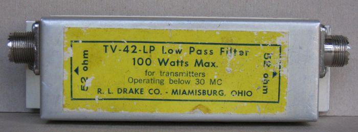
7 Filter Electronic are electronic circuits which perform signal processing functions, specifically intended to remove unwanted signal components and/or enhance wanted ones. Low-pass filter - Low frequencies are passed, high frequencies are attenuated. High-pass filter - High frequencies are passed, Low frequencies are attenuated. Band-pass filter - Only frequencies in a frequency band are passed. Band-stop filter - Only frequencies in a frequency band are attenuated Attenuated or Attenuation is the reduction in amplitude and intensity of a signal
8 Filters LOW PASS BAND PASS HIGH PASS BAND STOP
9 Regulator A voltage regulator is an electrical regulator designed to automatically maintain a constant voltage level. Voltage-Regulator-IEC-Symbol
10 Regulated Power Supply 120 or 240 volt AC Transfers electrical energy from one circuit to another Converts alternating current to direct current Remove unwanted signal components and/or enhance wanted ones Well-regulated lower voltage DC 12v Automatically maintain a constant voltage level
11 Frequency Modulation Receiver
12 Heterodyning Heterodyning is the generation of new frequencies by mixing two or more signals in a nonlinear device such as a vacuum tube, transistor, diode mixer. The mixing of each two frequencies results in the creation of two new frequencies, one at the sum of the two frequencies mixed, and the other at their difference. A heterodyne receiver is a telecommunication receiver which uses this effect to produce frequency shifts.
13 Superheterodyne Receiver The word heterodyne is derived from the Greek roots hetero- "different", and -dyne "power". A Superheterodyne Receiver converts any selected incoming frequency by heterodyne action to a preselected common intermediate frequency, for example, 455 kilohertz or 10.7 megahertz, and provides amplification and selectivity, or filtering. The term heterodyne is sometimes also applied to one of the new frequencies produced by heterodyne signal mixing.
14 Superheterodyne Receiver incoming radio frequencies from the antenna are made to mix (or multiply) with an internally generated radio frequency from the VFO in a process called mixing. The mixing process can produce a range of output signals: * at all the original frequencies, * at frequencies that are the sum of each two mixed frequencies * at frequencies that equal the difference between two of the mixed frequencies * at other, usually higher, frequencies. If the required incoming radio frequency and the VFO frequency were both rather high (RF) but quite similar, then by far the lowest frequency produced from the mixer will be their difference. In very simple radios, it is relatively straightforward to separate this from all the other spurious signals using a filter, to amplify it and then further to process it into an audible signal. In more complex situations, many enhancements and complications get added to this simple process, but this mixing or heterodyning principle remains at the heart of it.
15 Amplifier amplifier is any device that will use a small amount of energy to control a larger amount of energy. The relationship of the input to the output of an amplifier is usually expressed as a function of the input frequency and is called the transfer function of the amplifier, and the magnitude of the transfer function is termed the gain. gain is a measure of the ability of a circuit to increase the power or amplitude of a signal. It is usually defined as the mean ratio of the signal output of a system to the signal input of the same system. It may also be defined as the decimal logarithm of the same ratio.
16 Mixer mixer is a nonlinear circuit or device that accepts as its input two different frequencies and presents at its output a mixture of signals at several frequencies: the sum of the frequencies of the input signals the difference between the frequencies of the input signals both original input frequencies these are often considered parasitic and are filtered out. The manipulations of frequency performed by a mixer can be used to move signals between bands, or to encode and decode them. One other application of a mixer is as a product detector
17 Local Oscillator A local oscillator is a device used to generate a signal which is beat against the signal of interest to mix it to a different frequency. The oscillator produces a signal which is injected into the mixer along with the signal from the antenna in order to effectively change the antenna signal by heterodyning with it to produce the sum and difference (with the utilization of trigonometric angle sum and difference identities) of that signal one of which will be at the intermediate frequency which can be handled by the IF amplifier. These are the beat frequencies. Normally the beat frequency is associated with the lower sideband, the difference between the two.
18 Limiter a limiter is a circuit that allows signals below a set value to pass unaffected, as in a Class A amplifier, and clips off the peaks of stronger signals that exceed this set value, as in a Class C amplifier. Removes all traces of AM from the received signal, improves S2N ratio, removes static crashes
19 Demodulator A demodulator is an electronic circuit used to recover the information content from the carrier wave of a signal. The term is usually used in connection with radio receivers, but there are many kinds of demodulators used in many other systems. Another common one is in a modem, which is a contraction of the terms modulator/demodulator.
20 Frequency Discriminator The frequency discriminator controls the varicap. A varicap is used to keep the intermediate frequency (IF) stable. Gives our a faithful reproduction of the original audio Converts frequency variations to voltage variation varicap diode, varactor diode or tuning diode is a type of diode which has a variable capacitance Capacitance is a measure of the amount of electric charge stored
21 Intermediate Frequency An intermediate frequency (IF) is a frequency to which a carrier frequency is shifted as an intermediate step in transmission or reception. It is the beat frequency between the signal and the local oscillator in a radio detection system. IF is also the name of a stage in a superheterodyne receiver. It is where an incoming signal is amplified before final detection is done. There may be several such stages in a superheterodyne radio receiver.
22 Frequency Modulation Receiver heterodyne action to a pre-selected common intermediate frequency, 455 kilohertz signal beat against the signal of interest to mix it to a different frequency. the intermediate frequency (IF) is keep stable. signals below a set value pass unaffected, and clips off the peaks
23 Single-Sideband and CW Receiver
24 Envelope Detector An envelope detector is an electronic circuit that takes a highfrequency signal as input, and provides an output which is the "envelope" of the original signal. The capacitor in the circuit stores up charge on the rising edge, and releases it slowly through the resistor when the signal falls. The diode in series ensures current does not flow backward to the input to the circuit. Most practical envelope detectors use either half-wave or full-wave rectification of the signal to convert the AC audio input into a pulsed DC signal. Filtering is then used to smooth the final result. This filtering is rarely perfect and some "ripple" is likely to remain on the envelope follower output, particularly for low frequency inputs such as notes from a bass guitar. More filtering gives a smoother result, but decreases the responsiveness of the design, so real-world solutions are a compromise.


25 Envelope Detector A signal and its envelope marked with red simple envelope demodulator circuit.
26 Product Detector A product detector is a type of demodulator used for AM and SSB signals. Rather than converting the envelope of the signal into the decoded waveform like an envelope detector, the product detector takes the product of the modulated signal and a local oscillator, hence the name. A product detector is a frequency mixer. Product detectors can be designed to accept either IF or RF frequency inputs. A product detector which accepts an IF signal would be used as a demodulator block in a superheterodyne receiver, and a detector designed for RF can be combined with an RF amplifier and a lowpass filter into a direct-conversion receiver.
27 Single-Sideband and CW Receiver
28 Receiver Receiver is an electronic circuit that receives its input from an antenna, uses electronic filters to separate a wanted radio signal from all other signals picked up by this antenna, amplifies it to a level suitable for further processing, and finally converts through demodulation and decoding the signal into a form usable for the consumer, such as sound, pictures, digital data, measurement values, navigational positions, etc.
29 Beat Frequency Oscillator or BFO A beat frequency oscillator or BFO in radio telegraphy, is a dedicated oscillator used to create an audio frequency signal from carrier wave transmissions to make them audible, as they are not broadcast as such. The signal from the BFO is then heterodyned with the intermediate frequency signal to create an audio frequency signal.
30 Variable Frequency Oscillator A variable frequency oscillator (VFO) is a component in a radio receiver or transmitter that controls the frequency to which the apparatus is tuned. It is a necessary component in any radio receiver or transmitter that works by the superheterodyne principle, and which can be tuned across various frequencies.
31 Single-Sideband Transmitter


32 Digital System
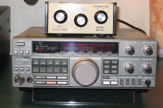
33 Placement of Component in a HF Station


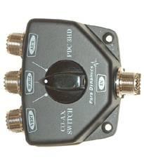

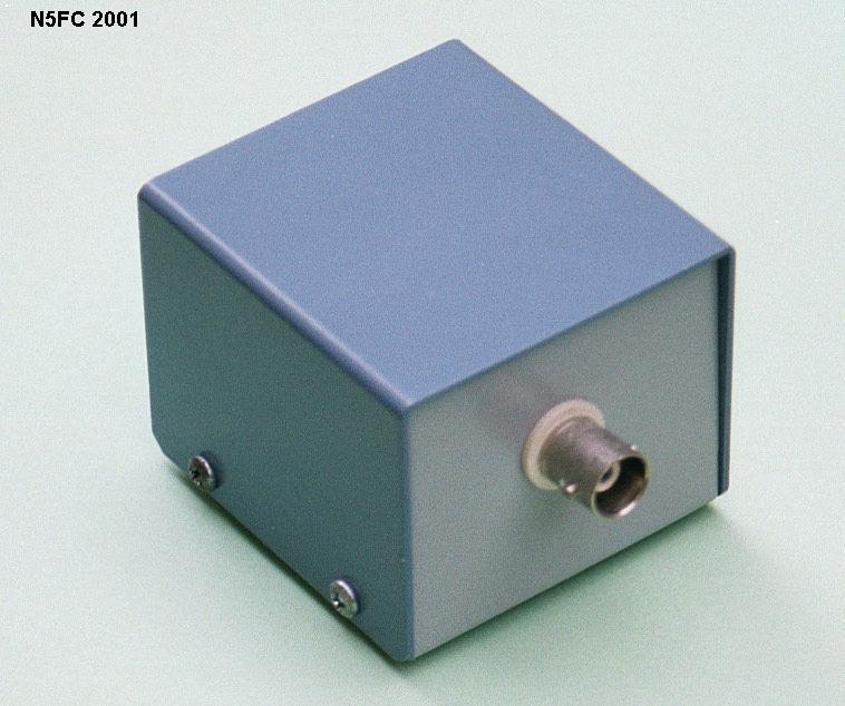
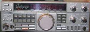
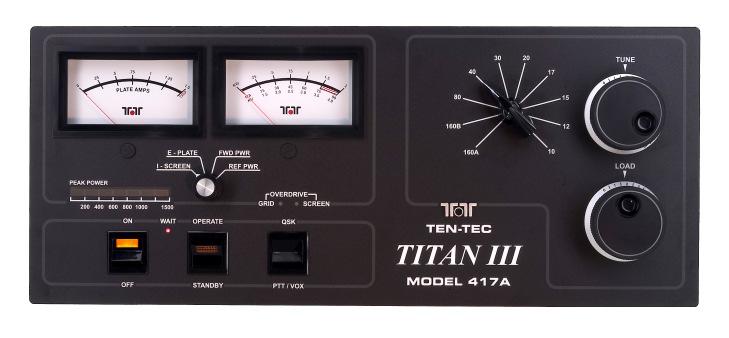
34 Placement of Component in a HF Station
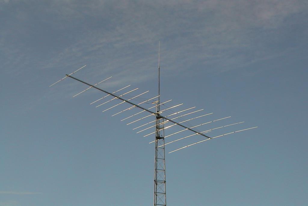
35 Yagi-Uda Three-Element Directional Antenna
36 SAFETY Building and operating a ham radio station is a perfectly safe pastime. However, carelessness can lead to severe injury, burns or even death by electrocution.. Antenna Safety Look Up and Live!
37 SAFETY Assume all overhead power lines are energized and dangerous. They are not covered! This includes the service drop, which typically runs from the power pole to your home or shack. Look for power lines which can be hidden by trees and buildings. Plan the work and work the plan. Before you put up or take down an antenna, assess the job; discuss the project s activities with your helpers and agree on specific assignments. Ask yourself at any time can arms, legs, head, the antenna, wires or tools come in contact with power lines? Use a safety spotter. Nobody can do the work alone and assess safety distances. A safety spotter s only job it to keep people and equipment safely away from power lines. Remember the 10-foot rule. Keep all equipment, tools, your antenna, guy wire and tower at least 10 feet away from power lines.
38 SAFETY Never use metal ladders or long-handled metal tools when working near power lines. Make sure the antenna cannot be rotated into power lines. Or that it cannot fall into a power line if the guy wires fail and the tower falls. Use non-conductive guys. Have a solid earth ground for your antenna and operating equipment. This helps reduce the risk of electrical shock and also provides a low-impedance path to ground for stray RF.
39 SAFETY Outdoor antennas should be grounded with an approved lighting arresting device. Local codes may apply. The radio should also be grounded to an earth ground to help protect both the radio and its user Antenna mast, cable, and guy wires are all excellent conductors of electrical current. If the tower assembly starts to drop... get away from it and let it fall. DO NOT use hot water pipes or gas lines as a ground source. DO NOT place antennas where People or Animals are likely to run into or encounter DON T BE AFRAID TO ASK QUESTSION OR ASK FOR ASSISTANCE
40 "Safety Code 6" The rules and guidelines covering the subject of RF Safety, are published by the Federal Government in a document entitled "Safety Code 6" Limits of Human Exposure to Radiofrequency Electromagnetic Fields in the Frequency Range from 3 KHZ to 300 GHZ - Safety Code 6
41 "Safety Code 6" RF energy has thermal effects (i.e., it can cause body heating) if the power density is high enough. The thermal effects of RF energy can include blindness and sterility, among other health problems
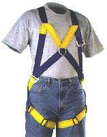
42 Good practices to follow when putting up your antenna s At least two people to do the job. Three is better. Equipment Safety Belt Safety Rope / use of it while climbing No Mold inside ( twist open to inspect it ) Proper Length Tool Pouch: Roomy, not packed full Clothing Close fitting, not sloppy, not tight Gloves ( for protection and warmth ) NO Sneakers, Hard Soles, Good fit
43 Safety belt For your safety it is of the uttermost importance that you borrow or buy a safety belt. This is in fact a generic term that we must divide in 2 elements : first, the leather belt, at least 5 cm wide or 2", which length is adjustable to the perimeter of the tower like an ordinary belt. It is independent of the security hardness (but has to be attached on it). Then you need either of a strap snap or a safety belt with seat harness that you will attach around your waist. This is a 10 cm wide (4") belt including a leather belt and some fasteners to attach various steel loops or tools.


44 Safety belt
45 What is a gin pole? A gin pole, or raising fixture, provides this safety by giving the tower climber the needed heavy lifting ability the ground person provides. A gin pole consists of 3 basic parts: (1) a pulley assembly to provide mechanical advantage when lifting, (2) a pole to gain height needed for the lift, and (3) the clamp assembly to attach everything to the tower. Typically the ground person does the heavy lifting, while the tower person above has the freedom to guide and fasten the tower and antenna components together. Proper use of a gin pole provides a controllable and safe method to erect and maintain a tower and antenna assembly, use it!


46 What is a gin pole?
Block Diagrams Definitions & Safety Lesson 3 From: Emergency Management Ontario
 Block Diagrams Definitions & Safety Regulated Power Supply Power supply A power supply (sometimes known as a power supply unit or PSU) is a device or system that supplies electrical or other types of energy
CHAPTER 13 TRANSMITTERS AND RECEIVERS
 CHAPTER 13 TRANSMITTERS AND RECEIVERS Frequency Modulation (FM) Receiver Frequency Modulation (FM) Receiver FREQUENCY MODULATION (FM) RECEIVER Superheterodyne Receiver Heterodyning The word heterodyne
Technician License Course Chapter 3 Types of Radios and Radio Circuits. Module 7
 Technician License Course Chapter 3 Types of Radios and Radio Circuits Module 7 Radio Block Diagrams Radio Circuits can be shown as functional blocks connected together. Knowing the description of common
NEW YORK CITY COLLEGE of TECHNOLOGY THE CITY UNIVERSITY OF NEW YORK DEPARTMENT OF ELECTRICAL ENGINEERING AND TELECOMMUNICATIONS TECHNOLOGIES
 NEW YORK CITY COLLEGE of TECHNOLOGY THE CITY UNIVERSITY OF NEW YORK DEPARTMENT OF ELECTRICAL ENGINEERING AND TELECOMMUNICATIONS TECHNOLOGIES Course : EET 24 Communications Electronics Module : AM Tx and
Amateur Radio Examination EXAMINATION PAPER No. 275 MARKER S COPY
 01-6-(d) An Amateur Station is quoted in the regulations as a station: a for training new radio operators b using amateur equipment for commercial purposes c for public emergency purposes d in the Amateur
Radio Receivers. Al Penney VO1NO
 Radio Receivers Al Penney VO1NO Role of the Receiver The Antenna must capture the radio wave. The desired frequency must be selected from all the EM waves captured by the antenna. The selected signal is
Television and video engineering
 Television and video engineering Unit-4 Television Receiver systems Objectives: To learn the requirements of TV receiver Study of monochrome and Colour TV receivers. To learn functions of Tuning circuits
LAB Assignment No. 6: TO STUDY GENERATION OF DOUBLE SIDE BAND AMPLITUDE MODULATE (AM) WAVEFORMS, USING DSB/SSB TRANSMITTER
 WAVEFORMS, USING DSB/SSB TRANSMITTER") LAB Assignment No. 6: TO STUDY GENERATION OF DOUBLE SIDE BAND AMPLITUDE MODULATE (AM) WAVEFORMS, USING DSB/SSB TRANSMITTER APPARATUS: Oscilloscope DSB/SSB Traine Power supply Connecting leads THEORY: A
LAB Assignment No. 6: TO STUDY GENERATION OF DOUBLE SIDE BAND AMPLITUDE MODULATE (AM) WAVEFORMS, USING DSB/SSB TRANSMITTER APPARATUS: Oscilloscope DSB/SSB Traine Power supply Connecting leads THEORY: A
AM Generation High Level Low Level
 AM Generation High Level Low Level Low-level generation In modern radio systems, modulated signals are generated via digital signal processing (DSP). With DSP many types of AM modulation are possible with
Module 8 Theory. dbs AM Detector Ring Modulator Receiver Chain. Functional Blocks Parameters. IRTS Region 4
 Module 8 Theory dbs AM Detector Ring Modulator Receiver Chain Functional Blocks Parameters Decibel (db) The term db or decibel is a relative unit of measurement used frequently in electronic communications
PRACTICE. Amateur Radio Operator Certificate Examination. Advanced Qualification
 Amateur Radio Operator ertificate Examination Advanced Qualification 2019-04-03 To pass this exam, you must correctly answer 35 out of 50 questions Exam Number: 115916 1. (A-007-008-002) Why would one
AM, PM and FM mo m dula l ti t o i n
 AM, PM and FM modulation What is amplitude modulation In order that a radio signal can carry audio or other information for broadcasting or for two way radio communication, it must be modulated or changed
4/30/2012. General Class Element 3 Course Presentation. Practical Circuits. Practical Circuits. Subelement G7. 2 Exam Questions, 2 Groups
 General Class Element 3 Course Presentation ti ELEMENT 3 SUB ELEMENTS General Licensing Class Subelement G7 2 Exam Questions, 2 Groups G1 Commission s Rules G2 Operating Procedures G3 Radio Wave Propagation
Chapter 3. Question Mar No
 Chapter 3 Sr Question Mar No k. 1 Write any two drawbacks of TRF radio receiver 1. Instability due to oscillatory nature of RF amplifier.. Variation in bandwidth over tuning range. 3. Insufficient selectivity
Radio Receivers. Al Penney VO1NO
 Radio Receivers Role of the Receiver The Antenna must capture the radio wave. The desired frequency must be selected from all the EM waves captured by the antenna. The selected signal is usually very weak
Amateur Radio License. Safety
 Amateur Radio License Safety Exam 35 questions, you have to get 26 right There will be multiple exams available, you can try again immediately There will also be General (and Extra!) class tests if you
Radio Merit Badge Boy Scouts of America
 Radio Merit Badge Boy Scouts of America Module 2 Electronics, Safety & Careers BSA National Radio Scouting Committee2012 Class Format Three modules any order Module 1 Intro To Radio Module 2 Electronic
Topic Advanced Radio Receivers. Explain that an RF amplifier can be used to improve sensitivity;
 Learning Objectives: At the end of this topic you will be able to; Explain that an RF amplifier can be used to improve sensitivity; Explain that a superheterodyne receiver offers improved selectivity and
Tuned Radio Frequency Receiver (TRF) The most elementary receiver design, consisting of RF amplifier stages, detector and audio amplifier stages.
 The most elementary receiver design, consisting of RF amplifier stages, detector and audio amplifier stages.") Figure 3-1 Simple radio receiver block diagram. Tuned Radio Frequency Receiver (TRF) The most elementary receiver design, consisting of RF amplifier stages, detector and audio amplifier stages. Jeffrey
Figure 3-1 Simple radio receiver block diagram. Tuned Radio Frequency Receiver (TRF) The most elementary receiver design, consisting of RF amplifier stages, detector and audio amplifier stages. Jeffrey
Technician Licensing Class. Lesson 4. presented by the Arlington Radio Public Service Club Arlington County, Virginia
 Technician Licensing Class Lesson 4 presented by the Arlington Radio Public Service Club Arlington County, Virginia 1 Quiz Sub elements T6 & T7 2 Good Engineering Practice Sub element T8 3 A Basic Station
Introduction to Receivers
 Introduction to Receivers Purpose: translate RF signals to baseband Shift frequency Amplify Filter Demodulate Why is this a challenge? Interference Large dynamic range required Many receivers must be capable
Definitions of Technical Terms
 Definitions of Technical Terms Terms Ammeter Amperes, Amps Band Capacitor Carrier Squelch Diode Dipole Definitions How is an ammeter usually connected = In series with the circuit What instrument is used
Amateur Radio Examination EXAMINATION PAPER No. 260 MARKER S COPY
 01-7-(a) An authorised officer from the Ministry of Business, Innovation & Employment can inspect a General Amateur Operator's Certificate of Competency: a at any time b during business hours c at any
Chapter 3. Electricity, Components and Circuits. Metric Units
 Chapter 3 Electricity, Components and Circuits Metric Units 1 T5B02 -- What is another way to specify a radio signal frequency of 1,500,000 hertz? A. 1500 khz B. 1500 MHz C. 15 GHz D. 150 khz T5B07 --
1. What is the unit of electromotive force? (a) volt (b) ampere (c) watt (d) ohm. 2. The resonant frequency of a tuned (LRC) circuit is given by
 volt (b) ampere (c) watt (d) ohm. 2. The resonant frequency of a tuned (LRC) circuit is given by") Department of Examinations, Sri Lanka EXAMINATION FOR THE AMATEUR RADIO OPERATORS CERTIFICATE OF PROFICIENCY ISSUED BY THE DIRECTOR GENERAL OF TELECOMMUNICATIONS, SRI LANKA 2004 (NOVICE CLASS) Basic Electricity,
Department of Examinations, Sri Lanka EXAMINATION FOR THE AMATEUR RADIO OPERATORS CERTIFICATE OF PROFICIENCY ISSUED BY THE DIRECTOR GENERAL OF TELECOMMUNICATIONS, SRI LANKA 2004 (NOVICE CLASS) Basic Electricity,
General Class License Theory II. Dick Grote K6PBF
 General Class License Theory II Dick Grote K6PBF k6pbfdick@gmail.com 1 Introduction In the first theory class we talked about basic electrical principles and components. Now we will build on this to learn
Twelve voice signals, each band-limited to 3 khz, are frequency -multiplexed using 1 khz guard bands between channels and between the main carrier
 Twelve voice signals, each band-limited to 3 khz, are frequency -multiplexed using 1 khz guard bands between channels and between the main carrier and the first channel. The modulation of the main carrier
Technician License Course Chapter 3. Lesson Plan Module 7 Types of Radio Circuits
 Technician License Course Chapter 3 Lesson Plan Module 7 Types of Radio Circuits The Basic Transceiver Combination of transmitter and receiver Abbreviated XCVR (X = trans) Antenna switched between transmitter
Transmitters and receivers
 Chapter 3 Transmitters and receivers Transmitters and receivers are used extensively in aircraft communication and navigation systems. In conjunction with one ore more antennas, they are responsible for
Amateur Radio Examination EXAMINATION PAPER No. 276 MARKER S COPY
 01-3-(a) The Amateur Service in New Zealand is administered through this prime document: a the New Zealand Radiocommunications Regulations b the Broadcasting Act c the Telecommunications Act d the Radio
OBJECTIVES EQUIPMENT LIST
 1 Reception of Amplitude Modulated Signals AM Demodulation OBJECTIVES The purpose of this experiment is to show how the amplitude-modulated signals are demodulated to obtain the original signal. Also,
Description of the AM Superheterodyne Radio Receiver
 Superheterodyne AM Radio Receiver Since the inception of the AM radio, it spread widely due to its ease of use and more importantly, it low cost. The low cost of most AM radios sold in the market is due
HF Receivers, Part 2
 HF Receivers, Part 2 Superhet building blocks: AM, SSB/CW, FM receivers Adam Farson VA7OJ View an excellent tutorial on receivers NSARC HF Operators HF Receivers 2 1 The RF Amplifier (Preamp)! Typical
Ham Radio Safety In & Out Of The Shack
 Ham Radio Safety In & Out Of The Shack Areas of Discussion Electrical Safety AC Power Grounding Antenna Safety Mobile Installations Electrical Safety AC Safety Grounding Most ham stations DO NOT require
The G4EGQ RAE COURSE Lesson 9 Transmitters Lesson 8 looked at a simple transmitter exciter comprising of oscillator, buffer and multiplier stages.
 Lesson 8 looked at a simple transmitter exciter comprising of oscillator, buffer and multiplier stages. The power amplifier The output from the exciter is usually very low and it is necessary to amplify
RADIO AMATEUR EXAM GENERAL CLASS
 RAE-Lessons by 4S7VJ 1 CHAPTER-5 RADIO AMATEUR EXAM GENERAL CLASS By 4S7VJ 5.1 RECEIVER The main purpose of a radio receiver is receive RF signal and convert to AF signal or get the audio signal out from
Chapter-15. Communication systems -1 mark Questions
 Chapter-15 Communication systems -1 mark Questions 1) What are the three main units of a Communication System? 2) What is meant by Bandwidth of transmission? 3) What is a transducer? Give an example. 4)
The New England Radio Discussion Society electronics course (Phase 4, cont d) Introduction to receivers
 Introduction to receivers") The New England Radio Discussion Society electronics course (Phase 4, cont d) Introduction to receivers AI2Q April 2017 REVIEW: a VFO, phase-locked loop (PLL), or direct digital synthesizer (DDS), can
The New England Radio Discussion Society electronics course (Phase 4, cont d) Introduction to receivers AI2Q April 2017 REVIEW: a VFO, phase-locked loop (PLL), or direct digital synthesizer (DDS), can
Charan Langton, Editor
 Charan Langton, Editor SIGNAL PROCESSING & SIMULATION NEWSLETTER Baseband, Passband Signals and Amplitude Modulation The most salient feature of information signals is that they are generally low frequency.
Amateur Radio Examination EXAMINATION PAPER No. 272 CANDIDATE S COPY
 01-9 The holder of a General Amateur Operator Certificate of Competency may: a retransmit public broadcasts b transmit in bands allocated to the Amateur Service c repair radio equipment for profit d transmit
RADIO RECEIVERS ECE 3103 WIRELESS COMMUNICATION SYSTEMS
 RADIO RECEIVERS ECE 3103 WIRELESS COMMUNICATION SYSTEMS FUNCTIONS OF A RADIO RECEIVER The main functions of a radio receiver are: 1. To intercept the RF signal by using the receiver antenna 2. Select the
The Electro-Magnetic Spectrum
 The Electro-Magnetic Spectrum Part Three In This Issue: All about Tubes How a diode rectifier works How a triode amplifier works How the mixer in your receiver works Dear Friends: For quite some time I
HF Receivers, Part 3
 HF Receivers, Part 3 Introduction to frequency synthesis; ancillary receiver functions Adam Farson VA7OJ View an excellent tutorial on receivers Another link to receiver principles NSARC HF Operators HF
1. General Outline Project Proposal April 9, 2014 Kayla Esquivel and Jason Yang
 1. General Outline 6.101 Project Proposal April 9, 2014 Kayla Esquivel and Jason Yang The invention and mass application of radio broadcast was triggered in the first decade of the nineteenth century by
User Guide. For. Model Alpha Loop (Sr)
") User Guide For Model Alpha Loop (Sr) Manufactured by: Alpha Antenna 1.888.482.3249 Website: http://alphaantenna.com User Guide Version 2.5 December 27, 2017 Page 1 Table of Contents Purpose... 4 Introduction...
User Guide For Model Alpha Loop (Sr) Manufactured by: Alpha Antenna 1.888.482.3249 Website: http://alphaantenna.com User Guide Version 2.5 December 27, 2017 Page 1 Table of Contents Purpose... 4 Introduction...
6.101 Project Proposal April 9, 2014 Kayla Esquivel and Jason Yang. General Outline
 6.101 Project Proposal April 9, 2014 Kayla Esquivel and Jason Yang General Outline We will build a superheterodyne AM Radio Receiver circuit that will have a bandwidth of the entire AM spectrum, and whose
ANALOG COMMUNICATION
 ANALOG COMMUNICATION TRAINING LAB Analog Communication Training Lab consists of six kits, one each for Modulation (ACL-01), Demodulation (ACL-02), Modulation (ACL-03), Demodulation (ACL-04), Noise power
N3ZI Kits General Coverage Receiver, Assembly & Operations Manual (For Jun 2011 PCB ) Version 3.33, Jan 2012
 Version 3.33, Jan 2012") N3ZI Kits General Coverage Receiver, Assembly & Operations Manual (For Jun 2011 PCB ) Version 3.33, Jan 2012 Thank you for purchasing my general coverage receiver kit. You can use the photo above as a
N3ZI Kits General Coverage Receiver, Assembly & Operations Manual (For Jun 2011 PCB ) Version 3.33, Jan 2012 Thank you for purchasing my general coverage receiver kit. You can use the photo above as a
NEAR EAST UNIVERSITY PROJECT OF ELECTRONICS EE: 821 RADIO RECEIVER. s~ 4: 1/~ ~ &.~ ~ : "[)~ :~&ted,eic, & &~ s~ to:~ ~"4L&"D1
~ :~&ted,eic, & &~ s~ to:~ ~4L&D1") NEAR EAST UNIVERSITY PROJECT OF ELECTRONICS EE: 821 RADIO RECEIVER s~ 4: 1/~ ~ &.~ ~ : 91412 "[)~ :~&ted,eic, & &~ &~ s~ to:~ ~"4L&"D1 CONTENTS ' = FREQUENCY MODULATION = RADIO * * Radiation of Electrical
NEAR EAST UNIVERSITY PROJECT OF ELECTRONICS EE: 821 RADIO RECEIVER s~ 4: 1/~ ~ &.~ ~ : 91412 "[)~ :~&ted,eic, & &~ &~ s~ to:~ ~"4L&"D1 CONTENTS ' = FREQUENCY MODULATION = RADIO * * Radiation of Electrical
PRACTICE. Amateur Radio Operator Certificate Examination. Advanced Qualification
 Innovation, Science and Economic Development Canada Innovation, Sciences et Développement économique Canada Amateur Radio Operator Certificate Examination Advanced Qualification 2018-06-30 To pass this
UNIT-3. Electronic Measurements & Instrumentation
 UNIT-3 1. Draw the Block Schematic of AF Wave analyzer and explain its principle and Working? ANS: The wave analyzer consists of a very narrow pass-band filter section which can Be tuned to a particular
4/29/2012. General Class Element 3 Course Presentation. Signals and Emissions. SignalSignals and Emissionsissions. Subelement G8
 General Class Element 3 Course Presentation ti ELEMENT 3 SUB ELEMENTS General Licensing Class Subelement G8 Signals and Emissions 2 Exam Questions, 2 Groups G1 Commission s Rules G2 Operating Procedures
How It Works The PPM Radio Control System: Part 1
 Technical M.E.C. Technical Note Note How It Works The PPM Radio Control System: Part 1 Foreword This Technical Note is divided into 3 parts to reduce the file size when downloading each section from the
VHF LAND MOBILE SERVICE
 RFS21 December 1991 (Issue 1) SPECIFICATION FOR RADIO APPARATUS: VHF LAND MOBILE SERVICE USING AMPLITUDE MODULATION WITH 12.5 khz CARRIER FREQUENCY SEPARATION Communications Division Ministry of Commerce
6.101 Introductory Analog Electronics Laboratory
 6.101 Introductory Analog Electronics Laboratory Spring 2015, Instructor Gim Hom Project Proposal Transmitting, Receiving, and Interpreting ECG Waveforms Daniel Moon (dhmoon@mit.edu) Thipok (Ben) Rak-amnouykit
10 Safety earthing/grounding does not help EMC at RF
 1of 6 series Webinar #3 of 3, August 28, 2013 Grounding, Immunity, Overviews of Emissions and Immunity, and Crosstalk Contents of Webinar #3 Topics 1 through 9 were covered by the previous two webinars
Code No: R Set No. 1
 Code No: R05220405 Set No. 1 II B.Tech II Semester Regular Examinations, Apr/May 2007 ANALOG COMMUNICATIONS ( Common to Electronics & Communication Engineering and Electronics & Telematics) Time: 3 hours
Speech, music, images, and video are examples of analog signals. Each of these signals is characterized by its bandwidth, dynamic range, and the
 Speech, music, images, and video are examples of analog signals. Each of these signals is characterized by its bandwidth, dynamic range, and the nature of the signal. For instance, in the case of audio
Week 8 AM Modulation and the AM Receiver
 Week 8 AM Modulation and the AM Receiver The concept of modulation and radio transmission is introduced. An AM receiver is studied and the constructed on the prototyping board. The operation of the AM
Laboratory Assignment 5 Amplitude Modulation
 Laboratory Assignment 5 Amplitude Modulation PURPOSE In this assignment, you will explore the use of digital computers for the analysis, design, synthesis, and simulation of an amplitude modulation (AM)
G5A07 (D) What happens when the impedance of an electrical load is equal to the internal impedance of the power source?
 What happens when the impedance of an electrical load is equal to the internal impedance of the power source?") G5A07 (D) What happens when the impedance of an electrical load is equal to the internal impedance of the power source? A. The source delivers minimum power to the load B. The electrical load is shorted
G5A07 (D) What happens when the impedance of an electrical load is equal to the internal impedance of the power source? A. The source delivers minimum power to the load B. The electrical load is shorted
Modulation Methods Frequency Modulation
 Modulation Methods Frequency Modulation William Sheets K2MQJ Rudolf F. Graf KA2CWL The use of frequency modulation (called FM) is another method of adding intelligence to a carrier signal. While simple
Lesson 11: Antennas. Copyright Winters Version 1.0. Preparation for Amateur Radio Technician Class Exam
 Lesson 11: Antennas Preparation for Amateur Radio Technician Class Exam Topics Antenna ½ wave Dipole antenna ¼ wave Vertical antenna Antenna polarization Antenna location Beam antennas Test Equipment Exam
4.1 REPRESENTATION OF FM AND PM SIGNALS An angle-modulated signal generally can be written as
 1 In frequency-modulation (FM) systems, the frequency of the carrier f c is changed by the message signal; in phase modulation (PM) systems, the phase of the carrier is changed according to the variations
Chapter 5 AM Receivers
 Chapter 5 AM Receivers Prepared by Prof.V.K.Jain 1 Lecture outcome After studying this lecture, you should be able to: Describe the basic superheterodyne system Choose suitable intermediate frequencies
User Guide for the Alpha QRP Loop Antenna
 User Guide for the Alpha QRP Loop Antenna Manufactured by: Alpha Antenna 1.888.482.3249 Website: http://alphaantenna.com User Guide Version 2.0 Page 1 Table of Contents Introduction... 3 Product Overview...
 UNIT I FUNDAMENTALS OF ANALOG COMMUNICATION Introduction In the Microbroadcasting services, a reliable radio communication system is of vital importance. The swiftly moving operations of modern communities
Internal Examination I Answer Key DEPARTMENT OF CSE & IT. Semester: III Max.Marks: 100
 NH 67, Karur Trichy Highways, Puliyur C.F, 639 114 Karur District Internal Examination I Answer Key DEPARTMENT OF CSE & IT Branch & Section: II CSE & IT Date & Time: 06.08.15 & 3 Hours Semester: III Max.Marks:
Chapter 6: Power Amplifiers
 Chapter 6: Power Amplifiers Contents Class A Class B Class C Power Amplifiers Class A, B and C amplifiers are used in transmitters Tuned with a band width wide enough to pass all information sidebands
User Guide for the Alpha Loop Jr+ Antenna
 User Guide for the Alpha Loop Jr+ Antenna Manufactured by: Alpha Antenna 1.888.482.3249 Website: http://alphaantenna.com User Guide Version 3.1 Page 1 Table of Contents Introduction... 3 Product Overview...
Trees, vegetation, buildings etc.
 EMC Measurements Test Site Locations Open Area (Field) Test Site Obstruction Free Trees, vegetation, buildings etc. Chamber or Screened Room Smaller Equipments Attenuate external fields (about 100dB) External
Amateur Wireless Station Operators License Exam
 Amateur Wireless Station Operators License Exam Study material 2017 South India Amateur Radio Society, Chennai CHAPTER 4 1 Chapter 4 Amateur Wireless Station Operators License Exam Study Material Chapter
AM radio / FM IF stereo system IC
 AM radio / FM IF stereo system IC The is an AM radio and FM IF stereo system IC developed for radio cassette players. The FM circuit is comprised of a differential IF amplifier, a double-balance type quadrature
RF/IF Terminology and Specs
 RF/IF Terminology and Specs Contributors: Brad Brannon John Greichen Leo McHugh Eamon Nash Eberhard Brunner 1 Terminology LNA - Low-Noise Amplifier. A specialized amplifier to boost the very small received
Treetop Circuits Owner s Manual for SB-SB-600 Adapter Version 1
 The SB-600 SSB adapter from Treetop Circuits (Fig. 1) is designed specifically as an accessory to the Hammarlund SP-600 series of receivers. It provides enhanced performance on SSB and CW signals, using
KWM-2/2A Transceiver THE COLLINS KWM-2/2A TRANSCEIVER
 KWM-2/2A Transceiver Click the photo to see a larger photo Click "Back" button on browser to return Courtesy of Norm - WA3KEY THE COLLINS KWM-2/2A TRANSCEIVER Unmatched for versatility, dependability and
Lesson 9: Base Stations
 Lesson 9: Base Stations Preparation for Amateur Radio Technician Class Exam Topics Home Stations Basic Station Layout RTTY and Data Communications Station Accessories Wavelengths Feed Lines Impedance-matching
51J-4 COMMUNICATIONS RECEIVER
 51J-4 COMMUNICATIONS RECEIVER Transcribed from 520-5014-00 August 15, 1954 GENERAL DESCRIPTION The Collins 51J-4 Receiver is designed for communication applications where stability and dial accuracy of
Experiment 1: Instrument Familiarization (8/28/06)
") Electrical Measurement Issues Experiment 1: Instrument Familiarization (8/28/06) Electrical measurements are only as meaningful as the quality of the measurement techniques and the instrumentation applied
Electrical Measurement Issues Experiment 1: Instrument Familiarization (8/28/06) Electrical measurements are only as meaningful as the quality of the measurement techniques and the instrumentation applied
1. Explain how Doppler direction is identified with FMCW radar. Fig Block diagram of FM-CW radar. f b (up) = f r - f d. f b (down) = f r + f d
 = f r - f d. f b (down) = f r + f d") 1. Explain how Doppler direction is identified with FMCW radar. A block diagram illustrating the principle of the FM-CW radar is shown in Fig. 4.1.1 A portion of the transmitter signal acts as the reference
1. Explain how Doppler direction is identified with FMCW radar. A block diagram illustrating the principle of the FM-CW radar is shown in Fig. 4.1.1 A portion of the transmitter signal acts as the reference
2. Capacitors of 8µF, 4µF and 2µF are connected in Parallel. What is the effective Capacitance? (a) 1.14µF (b) 14µF (c) 14 F (d) 1.
 1.14µF (b) 14µF (c) 14 F (d) 1.") 1 DEPARTMENT OF EXAMINATION SRI LANKA EXAMINATION FOR THE AMATEUR RADIO OPERATORS CERTIFICATE OF PROFICIENCY ISSUED BY THE DIRECTOR OF TELECOMMUNICATIONS OF SRI LANKA-APRIL 1993 (GENERAL CLASS) Index No.
1 DEPARTMENT OF EXAMINATION SRI LANKA EXAMINATION FOR THE AMATEUR RADIO OPERATORS CERTIFICATE OF PROFICIENCY ISSUED BY THE DIRECTOR OF TELECOMMUNICATIONS OF SRI LANKA-APRIL 1993 (GENERAL CLASS) Index No.
Experiment 1: Instrument Familiarization
 Electrical Measurement Issues Experiment 1: Instrument Familiarization Electrical measurements are only as meaningful as the quality of the measurement techniques and the instrumentation applied to the
FDM- FREQUENCY DIVISION MULTIPLEXING
 FDM- FREQUENCY DIVISION MULTIPLEXING Multiplexing to refer to the combination of information streams from multiple sources for transmission over a shared medium Demultiplexing to refer to the separation
Interference & Suppression Page 59
 INTERFERENCE Interference & Suppression Page 59 Front-End Overload, Cross-Modulation What is meant by receiver overload? Interference caused by strong signals from a nearby transmitter What is one way
COMM 704: Communication Systems
 COMM 704: Communication Lecture 1: Introduction Dr. Mohamed Abd El Ghany, Mohamed.abdel-ghany@guc.edu.eg Course Objective Give an introduction to the basic concepts of electronic communication systems
Amateur Radio Examination Intermediate Level
 Amateur Radio Examination Intermediate Level Candidate: Candidate DoB: Centre: Exam Date: This paper consists of 45 questions Time Allowed: 1 hour 25 minutes. Candidate Declaration. I confirm that this
ANNEX 6: EXAMINATION SYLLABUS AND REQUIREMENTS FOR A HAREC INTRODUCTION
 RECOMMENDATION T/R 61-02 Page 12 ANNEX 6: EXAMINATION SYLLABUS AND REQUIREMENTS FOR A HAREC INTRODUCTION This syllabus has been produced for the guidance of the administrations so that they may prepare
Amateur Wireless Station Operators License Exam
 Amateur Wireless Station Operators License Exam Study material 2017 South India Amateur Radio Society, Chennai CHAPTER 5 1 Chapter 5 Amateur Wireless Station Operators License Exam Study Material Chapter
RCA Radiola 60 REG. U.S. PAT. OFF.
 RCA Radiola 60 REG. U.S. PAT. OFF. Super-Heterodyne AC Socket-Powered Instructions IB-60-1 Radio Corporation of America 233 Broadway New York City 100 West Monroe Street 235 Montgomery Street Chicago,
Amplitude Modulated Systems
 Amplitude Modulated Systems Communication is process of establishing connection between two points for information exchange. Channel refers to medium through which message travels e.g. wires, links, or
Elements of Communication System Channel Fig: 1: Block Diagram of Communication System Terminology in Communication System
 Content:- Fundamentals of Communication Engineering : Elements of a Communication System, Need of modulation, electromagnetic spectrum and typical applications, Unit V (Communication terminologies in communication
UNIT 2. Q.1) Describe the functioning of standard signal generator. Ans. Electronic Measurements & Instrumentation
 Describe the functioning of standard signal generator. Ans. Electronic Measurements & Instrumentation") UNIT 2 Q.1) Describe the functioning of standard signal generator Ans. STANDARD SIGNAL GENERATOR A standard signal generator produces known and controllable voltages. It is used as power source for the
UNIT 2 Q.1) Describe the functioning of standard signal generator Ans. STANDARD SIGNAL GENERATOR A standard signal generator produces known and controllable voltages. It is used as power source for the
070 ELECTRONICS WORKS EXAMINATION STRUCTURE
 070 ELECTRONICS WORKS EXAMINATION STRUCTURE The trade will be examined under the following components or subject grouping: Electronic Devices and Circuit, Radio Communication and Television. EXAMINATION
Vintage Radio Alignment: What It Is and How to Do It
 Vintage Radio Alignment: What It Is and How to Do It Copyright 2009 Bret s Old Radios Bret Menassa Member: ARCI, VRPS, OKVRC Presented at Radiofest 2009, Willowbrook,, IL Vibrations A musical instrument
CHAPTER -15. Communication Systems
 CHAPTER -15 Communication Systems COMMUNICATION Communication is the act of transmission and reception of information. COMMUNICATION SYSTEM: A system comprises of transmitter, communication channel and
An Introduction to Analog Communications Student Workbook AT02
 LJ Technical Systems An Introduction to Analog Communications AT02 MT191/B LJ Technical Systems This publication is copyright and no part of it may be adapted or reproduced in any material form except
Norfolk Amateur Radio Club
 Norfolk Amateur Radio Club The Transmitter & Transmitter Interference Nick M0HGU & Steve G3PND Plan for the Day The Transmitter Introduction, Block diagrams Oscillators, Buffers & Multipliers Modulation
User Guide for the Alpha Loop Sr Antenna
 User Guide for the Alpha Loop Sr Antenna Manufactured by: Alpha Antenna 1.888.482.3249 Website: http://alphaantenna.com Available from: Amateur Radio Store Website: https://amateurradiostore.com User Guide
CHAPTER 6 Radio Circuits and Systems
 6.1 AMPLIFIERS (page 6-1) CHAPTER 6 Radio Circuits and Systems AMPLIFIER GAIN (page 6-2) INPUT AND OUTPUT IMPEDANCE (page 6-2) DISCRETE DEVICE AMPLIFIERS (page 6-2) BASIC CIRCUITS (page 6-2) COMMON-EMITTER
Contents. 1. Fundamentals of Amplification The Small-Signal Pentode 40. Acknowledgements. Some Useful Formulae
 Contents Preface Acknowledgements Some Useful Formulae vii ix x 1. Fundamentals of Amplification 1 1.1: Basic Theory of Valves 2 1.2: Valve Diodes 2 1.3: Triodes 4 1.4: Anode Resistance, r a 6 1.5: Amplification