PATRIOT DOCKS ASSEMBLY INSTRUCTIONS
|
|
|
- Wesley Quinn
- 6 years ago
- Views:
Transcription


. Please refer to www.patriotdocks.")

1 6/1/2008 PATRIOT DOCKS ASSEMBLY INSTRUCTIONS Congratulations on your new Patriot Dock purchase. This manual contains instructions to assemble basic dock configurations for use at typical shoreline application. It is possible to add sections and combine configurations to the basic configurations as long as installation guidelines are adhered to (subject to lake and shoreline conditions). Please refer to for answers to frequently asked questions and other suggestions. US Dock and Hardware LLC Harris, MN (651)
2 STRAIGHT SECTIONAL DOCKS STRAIGHT ROLL-IN DOCKS ROLL-IN PATIO DOCKS General Guidelines: 1. Maximum recommended unsupported span for Patriot Aluminum Dock Frames is 16 feet. Always support outside corners. Use additional posts to add stability as necessary. 2. Always use Patriot Dock Pipe Post Brackets (PN 10810), Post Foot Plates (PN 10811) and 1½ Schedule 40 galvanized pipe (PN ) for support posts on Patriot Docks. Installing other parts may result in an unstable dock or unsafe installation. 3. Always install Vinyl Pipe Caps (PN 10823) on top of support pipes to avoid injury from sharp edges. 4. Never leave the end of the dock unsupported. Always support both corners of the Patio platform. Roll-in kits should be installed at the very end of the dock for best stability. Additional posts may be required if roll-in kits are installed at locations other than shown above. 5. Always assemble the dock frame so there is a 4-foot End Rail (PN 10803) at the ends of the dock. For patio or platform docks, two End Rails are required (may have to be purchased separately). For straight sectional docks only one End Rail is required. If lateral sections are to be added to the sectional dock (to form an L-shape), a separate End Rail is not required. 6. When adding lateral frame sections to create an L-shaped configuration (not shown in basic configurations), install the LAKE end (Connector Rail end) of the added frame towards the straight main dock. Add two Support Pipes to the end of every lateral section. 7. Install the Pipe Brace Kit PN in conjunction to the Roll-In Kit for lakes with soft bottoms or deep water applications. The brace kit will help prevent potential bending of the Support Pipes. 8. Always secure supports posts and level dock before installing deck panels. Remove decking panels whenever possible when pulling the frame out of the water to prevent bending the dock frame. 9. Maximum recommended distance between wheel kits for long dock applications is 32 feet. 10. Secure poly decking with cable ties as necessary to prevent shifting. Wear protective gloves. File any sharp edges on pipes and frame to avoid cuts or scrapes. If you have parts missing, contact your dealer before proceeding. For accessories, replacement parts, FAQ and warranty information, and detailed assembly directions with hints, please visit


 Side Frames (2) Middle Rails (1)")
 3/8-16 X 1.")


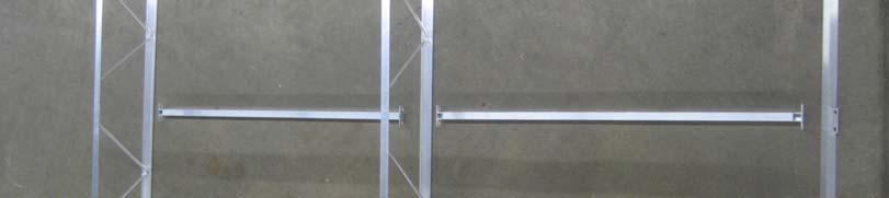
3 TOOLS NEEDED 9/16 and ¾ Wrenches & Ratchet w/sockets Hammer Phillips Screwdriver or Drill May Be Required: Knife Drill with 3/8 Bit Flat File ½ (12mm) Socket Pliers COMPONENT IDENTIFICATION 1. The 4 x 8 Aluminum Truss Frame, PN includes the following components: (2) Side Frames (2) Middle Rails (1) Connector Rail (Same as End Rail PN 10803) (2) Center Tubes 8 ft Diagonal Brace (12) 3/8-16 X 1.0 Bolts/Nuts (1I) Long and (1) Short (6) 3/8-16 X 1.62 Bolts/Nuts 2. The Support Post Assembly, PN includes 1½ Schedule 40 Galvanized Support Pipe available in 4 ft, 6 ft, 8 ft and 10 ft lengths plus the following components: (1) Pipe Post Bracket (1) Post Foot Plate (1) Vinyl Cap PN PN PN 10823
 or in Poly Dock-Top")


; and 8 Wide Roll-In Kits (PN")


 Axle")
 Plastic Wheel PN 10820 PN 10822 PN")
4 3. Decking is available in Cedar Drop-in Sections (PN 10870) or in Poly Dock-Top Sections (PN10860). Four molded Dock Tops and at least 6 Deck Clips (PN 10869) are required to assemble each 4x4 Poly Dock- Top Section. Cedar Deck Section Poly Dock-Top Section Deck Clips PN PN PN Various Roll-in Kits are available for Patriot Docks: Shore End Roll-In Kit (PN 10824) with 4-ft axle and 4-ft posts for shore end or shallow applications; 4 Wide Roll-In Kit (PN 10825) with 4-ft axle and 6-ft posts for straight dock applications (note: posts may be ordered longer as necessary); and 8 Wide Roll-In Kits (PN 10826) with 8-ft axle and 8-ft posts for patio/platform docks. The wheel adds one foot to support height. Each Roll-in Kit includes 2 Pipe Post Brackets, 2 Support Pipes, Axle Pipe, Wheel Clamps, Washers and Wheels (1) Axle Converter (pair) (1) Wheel Clamp (pair) (2) Plastic Wheel PN PN PN Optional Deep Water Pipe Brace Kit Deck Lockers PN PN 10867


5 PATRIOT DOCK ASSEMBLY INSTRUCTIONS: SHORE END LAKE END SHORE END SHORE END LAKE END LAKE END
6 ASSEMBLE ALUMINUM FRAME: 1. Lay out each 4 ft X 8 ft Aluminum Frame Assembly PN end to end in the desired basic configuration on a flat surface. Remove each component from the 4 ft X 8 ft Aluminum Frame Assembly packages and unwrap the protective plastic from the components. Place the 8-ft long Side Frame Rails in two lines making sure the ends marked SHORE are pointing to one direction and the ends marked LAKE are pointed in the opposite direction. Place the End and Middle Rails and Connector Rail between the Side Frame Rails as shown. 2. Starting from the left SHORE end of the layout, fasten the 4ft End Frame Rail to the Side Frame Rails using (4) 3/8-16 X 1.0 inch bolts and nuts for each. Position each end inside the vertical corner angle of the Side Frames. Finger-tighten bolts and nuts until all frame components are assembled. 3. Fasten the center 4ft Middle Frame Rail to the Side Frame Rails using (4) 3/8-16 X 1.0 inch bolts and nuts. Again, position each end inside the vertical angle on the Side Frames. 4. Position the 4 ft Connector Frame Rail to the Side Frame Rails using (2) 3/8-16 X inch bolts but do not install the nuts yet. Make sure the welded tab on the Connector Frame Rail faces away from the assembled frame. 5. Install the Short Center Tube Support between the End and Middle Frame Rails on the SHORE end of the first 4X8 Frame Rail Assembly and install the Long Center Tube Support between the Middle Frame Rail and the Connector Rail on the Lake end of the frame assembly. Use (4) 3/8-16 X 1.0 inch bolts and nuts and (2) 3/8-16 X inch bolts and nuts. Note: The (2) longer bolts are passed through the Connector Rail and the next Middle Frame Rail. 6. Move on to next connecting 4x8 Frame Assembly. Loosely fasten the next set of Side Frame Rails AND the End Frame Rail of the second frame to the first set of Side Frame Rails using the 3/8-16 X inch bolts and nuts in step 4. The Connector Rail of the first Frame Assembly stays in place. 7. Install an additional (2) 3/8-16 X bolts nuts and bolts to secure the bottom of the Side Frame Rails and Middle Frame Rail. Note: The End and Middle Frame Rails and Connector Frame Rails are always positioned inside the welded vertical aluminum angles on the Side Frame Rails. 8. Continue fastening the Side Frames, Middle Frame Rails, Connector Frame Rails and Center Support Tubes by repeating steps 1-7 until the straight part of the dock frame is assembled. Fasten the final End Frame Rail PN (packaged separately) to the Lake end of the dock using (4) 3/8-16 X 1.0 bolts and nuts. If holes do not match up, use drill with 3/8 bit to size. Discard Lake end Connector Frame Rail. 9. Install diagonal aluminum Brace to the bottom of each Side Frame Rail pair using two 3/8-16 X 1.0 bolts and nut in an alternating pattern (reverse direction from one 8 ft frame to the next so braces form continuous zigzag). These can also be installed later for easier access to underside of frame. 10. Patio Docks: Attach 4x8 Frame section to side of last 4x8 Frame using (6) 3/8-16 X bolts and nuts. Make sure to face the SHORE end of the added Patio Frame facing the Shore end of the main dock frame. Fasten the End Frame Rail PN (packaged separately) to the Lake end of the dock using (4) 3/8-16 X 1.0 inch bolts and nuts. Discard Lake end Connector Frame Rail. Install ladder uprights now. 11. L-Docks: Lateral sections can only be added to the Lake end of an 8 ft Frame Assembly. The Lake end or Connector Frame Rail end of the lateral is fastened to the straight main sectional dock after main dock is placed. For T, repeat procedure so that the distance between ends of laterals is 20 ft total.
 using ½ - 13 X 1 inch bolts provided as shown on the basic configuration layouts.")

 through Pipe Post Brackets and install Foot Plate (PN 10811).")


7 12. Check to make sure the frame components are flush and tighten all bolted connections with tools. INSTALL PIPE SUPPORTS AND ROLL-IN KITS: 1. Install Pipe Post Brackets (PN 10810) using ½ - 13 X 1 inch bolts provided as shown on the basic configuration layouts. The nuts are slipped into the pockets and the shorter bolts fasten the brackets to the Side Frame Rail. The ½-13 X 1.25 inch bolts are stainless steel and should be screwed into the weld nuts on the Post Bracket. CAUTION: Maximum span between post supports is 16 feet. Shore Ramps require support posts at the shore end (use washers for spacers to install these post brackets). 2. Slip Support Pipe (PN ) through Pipe Post Brackets and install Foot Plate (PN 10811). For Roll-In Kits, install Axle Converters (PN 10820) instead of the foot plates, pointing the long part of the horizontal axle converters towards each other. 3. For Roll-In Kits, slip axle through pipe converters, slide wheels & washers in place and fasten Wheel Clamps to axle pipe to keep wheels in place. Maintain a 1/8 inch gap between wheel and Axle Converter when fastening clamp. For straight docks, use 6 ft axle pipe and fasten wheels to the ends of the pipe outside the dock frame. For Patio Docks, use 8 ft axle pipe and fasten the wheels inside the dock frame adjacent to the Axle Converters. Tighten bolts ½ turn after bolt contacts pipe. Retighten as necessary. Add optional Pipe Stabilizer Brace Kit by bolting one end to lower ½ inch diameter hole in welded vertical angle of dock frame located 4 ft towards shore from the Pipe Brackets for the Roll-In Kit. Use connector strap to connect other end to vertical pipe support on Roll-In Kit approximately 3 feet below dock frame. If there is not enough pipe, bolt brace to top hole on vertical angle of dock frame instead. 4. Carefully roll or set the dock in place. Additional helpers may be needed. Adjust pipe supports to level the dock. Use winch tool, jack, come-along or other means to raise or lower dock. Tighten set bolts on Pipe Post Brackets. Make sure the long aluminum frame braces are installed on the underside of frame. 5. Install Decking A) For pre-assembled Cedar Decking Sections, PN 10870, set 4 x 4 sections in openings in frame. B) For pre-assembled poly Dock-Top Sections, PN 10860, set 4 x 4 sections in openings in frame. Rotate each Deck Locker (if included) under frame side rails to secure the decking to the dock frame. Note: To assemble poly panel, lay 4 individual panels upside down (with Dock-Top logos in same direction) on a flat surface and install 6 Deck Connecting Clips PN at the panel joints approximately 12 inches from the edge as indicated below using a hammer. Install 4 or 6 Deck Lockers PN between the panels with screws in the pre-drilled holes located about 2-1/4 inches from the edge (mount with swivel end to outside of panel). Fewer Deck Lockers may be needed when creating a continuous decking sheet where all sections are connected with Deck Connecting Clips on permanent installations. Secure panels to Shore Ramps with cable ties or screws. CAUTION: Always secure decking to the frame using cable ties, screws or Deck Lockers.

8 View Assembly Photos, Hints, and FAQs at LIMITED WARRANTY US Dock and Hardware LLC provides a limited warranty for plastic Dock-Top decking panels to the original purchaser only when purchased from an authorized dealer. The Dock-Top is not warranted in conjunction with other products not manufactured by US Dock and Hardware LLC. INTENDED USE: Dock-Top panels are intended to be installed on marine docks as decking and are not intended for any other use. The limited warranty is valid only when used for the intended application. Purchasers should fully inspect each Dock-Top panel before installing. WARRANTY: Providing that Dock-Top are installed as per the instructions supplied, Redtail International LLC warrants that a) Dock- Top will not delaminate; b) Dock-Top will not rot; c) Dock-Top will not absorb water; d) Dock-Top will not degrade from UV rays (does not include fading or light discoloration); e) Dock-Top panels are sold is in accordance with published specifications and are free of material or workmanship defects. TERMS: US Dock and Hardware LLC provides a full repair or replacement warranty for the first two years after the purchase date and a prorated warranty from two to seven years after the date of purchase. The prorated warranty provides replacement at a percentage discount off the current manufacturer s suggested retail price (MSRP). US Dock and Hardware LLC may repair, replace or provide a full or partial refund at its sole discretion according to the following terms. The claimant must present the defective panels to the authorized dealer from which they were originally purchased along with the original purchase invoice or receipt. The dealer will then submit a warranty claim to US Dock and Hardware LLC. If US Dock and Hardware LLC certifies that the items are indeed defective, US Dock and Hardware LLC will repair, replace or provide a prorated discount on replacement of the defective Dock-Top panels as follows: Year 1: Full Replacement Year 2: Full Replacement Year 3: Replacement at 50% of MSRP Year 4: Replacement at 60% of MSRP Year 5: Replacement at 70% of MSRP Year 6: Replacement at 80% of MSRP Year 7: Replacement at 90% of MSRP WARRANTY LIMITATIONS: The successful performance of the Dock-Top panel is dependant upon many factors beyond our control. Therefore, except for such replacement or refund outlined above, US Dock and Hardware LLC: 1. MAKES NO WARRANTY OR GUARANTEE, EXPRESS OR IMPLIED, INCLUDING WARRANTIES OF FITNESS, and DESIGN CAPABILITY OR MERCHANTABILITY RESPECTING ITS PRODUCTS. 2. Under no circumstances shall US Dock and Hardware LLC be liable for any special, incidental or consequential damages including but not limited to: personal injury, property damage, damage to or loss of product, loss of profits or revenue. The price stated for the products is a consideration in limiting US Dock and Hardware LLC liability and buyers remedy. 3. This limited warranty shall not apply to any product subject to misuse due to common negligence or accident nor to any product made by the seller not used in accordance with the printed instructions or specifications of US Dock and Hardware LLC or that have been beyond the represented and rated capacity of the product. 4. This limited warranty is applicable only to those parties heretofore mentioned, and is not assignable, transferable nor will it insure to the benefit of any sub-purchaser of the original equipment manufacturer other than the original retail purchaser. 5. Application may be subject to local building codes and is the responsibility of the purchaser to adhere to. 6. As stated above, US Dock and Hardware LLC reserves the right to inspect all panels claimed to be defective or damaged under the terms of the warranty. 7. US Dock and Hardware LLC limits of warranty is defective material replaced, repaired, or credit against further purchases. All information and data provided at time of writing is believed to be accurate and complete, however, are provided without any guarantee or responsibility of any kind, expressed or implied. Suggestions or statements concerning possible use of products are made without representation that any such use is free from patent infringement and are not recommendations to infringe any patent. The user must be aware that other safety measures may be required if not stated herein.
General Guidelines:
 ASSEMBLY INSTRUCTIONS Congratulations on your new Patriot Dock purchase. This manual contains instructions to assemble basic dock configurations for use at typical residential shoreline application. Please
Roll In W/L Dock PAGE 1
 Roll In W/L Dock PAGE 1 1 2 3/8 X 1 CARRIAGE BOLT SS 3/8 FLANGE NUT BRASS 3 4 1/2-13 X 1.25 SQ BOLT SS 1/2 SQ NUT BRASS 5 3/8-16 X 2.5" BOLT SS PAGE 2 6 7 BRACE BRKT SINGLE AXLE TUBE 8 9 3" AXLE WASHER
Installation Instructions Cage Kit JK Unlimited (4-Dr) Part # 76902
 Part # 76902") Please read instructions entirely before installing this product. Drilling is required to install this part. Parts Included Qty Parts Included Qty Driver Front Upright 1 Pass Side Drill Template (7289)
Please read instructions entirely before installing this product. Drilling is required to install this part. Parts Included Qty Parts Included Qty Driver Front Upright 1 Pass Side Drill Template (7289)
Installation Instructions:
 NOTE: Carefully read entire instructions thoroughly before attempting to install this part. (SB76904) Parts Included Qty 94-241CA001 Front Upright: Drvr 1 94-241CA002 Front Upright: Pass 1 94-241CA003
M ACS Instructions
 APPLICABLE MODELS: Nissan Frontier 2005 and up short bed with Utili-Trak mounting rails PACKAGE CONTENTS 00-0060-M-01-1205 ACS Instructions Leitner Designs 25675 Taladro Circle Unit E Mission Viejo, CA
S48-L12-SC AND G48-L12-GC STEEL PORTA-DOCK S82 SC 6 X 12 PLATFORM AND G82 GC 6 X 12 PLATFORM
 PAGE 1 OF 6 PORTA-DOCK, INC. S48-L12-SC AND G48-L12-GC STEEL PORTA-DOCK S82 SC 6 X 12 PLATFORM AND G82 GC 6 X 12 PLATFORM Thank you for purchasing our product! *Please read these instructions and follow
Models 2230 and 2240
 Models 2230 and 2240 Overview... 2 Tools Needed... 2 Hardware...3 Assembly... 4-13 Installation... 14 Drawer Removal... 15 Operation... 15 Maintenance... 15 Accessories... 16 Limited Warranty... 16 Perform
Tilting Flat Panel Wall Mount Installation Guide
 Tilting Flat Panel Wall Mount Installation Guide Model: A580TM Easy installation Built-in level for easy positioning Safety bolts lock the TV on the mount Easy to adjust tilt angles: +5 to -15 degrees
PORTA-DOCK, INC. AP17 APD DS 4 X 16 T12 AW17 CPD DS 4 X 16 T12
 Page 1 of 7 PORTA-DOCK, INC. AP17 APD DS 4 X 16 T12 AW17 CPD DS 4 X 16 T12 *For Beige Decking Add the Letter B to Model* Thank you for purchasing out product! *Please read these instructions and follow
Tilting, Swiveling & Rotating Flat Panel Wall Mount
 Tilting, Swiveling & Rotating Flat Panel Wall Mount Model: VXA980TC +5 to -5 +5 to -5 Supports most 0-80 Flat Panel TVs Maximum Weight Capacity: 32 lbs. Supports VESA Sizes up to 600x500 For technical
Assembly Instructions for 12x16 Floating Dock
 Assembly Instructions for 12x16 Floating Dock www.rollingbarge.com Congratulations on the purchase of your Floating Dock kit. This kit includes all the aluminum frame parts, and all the fasteners. You
BOUNCE TABLE TENNIS TABLE & ACCESSORIES ASSEMBLY INSTRUCTIONS
 BOUNCE TABLE TENNIS TABLE & ACCESSORIES ASSEMBLY INSTRUCTIONS NG2325 THANK YOU! Thank you for your purchase of our product. We work around the clock and around the globe to ensure that our products maintain
Tilting & Swiveling Plasma/LCD Flat Panel Wall Mount Installation Guide Model: A380SM
 Tilting & Swiveling Plasma/LCD Flat Panel Wall Mount Installation Guide Model: A380SM Easy installation Built-in level for easy positioning Corrective leveling adjustments after installation Forward /
Cottage Style Dock Instructions
 Cottage Style Dock Instructions Table of Contents 1. Dock Assembly and Set-Up 1.1 Quick Start 1.2 Positioning Quick Clips 1.3 Installing Dock Legs 1.4 Installing Foot Pads 1.5 Installing Cross Braces 1.6
ASSEMBLY AND OPERATING INSTRUCTIONS FOR MODELS SD1200 AND SD2000
 ASSEMBLY AND OPERATING INSTRUCTIONS FOR MODELS SD1200 AND SD2000 WARNING: The watercraft ramp you have purchased has certain hazards associated with it s use. Never stand behind a watercraft while it is
Desk/Wall-Mount Rack
 Desk/Wall-Mount Rack Patent(s) Pending Installation Instructions Post P/N: 119-1752 119-1781 119-1782 119-4014 Frame P/N: 119-1591 119-1754 119-1755 Kit Contents (2) Frames (4) Posts Assembly Hardware
VAN STORAGE SOLUTIONS FOR THE WAY YOU WORK
 WWW.WEATHERGUARD.COM VAN STORAGE SOLUTIONS FOR THE WAY YOU WORK Weather Guard / KNAACK 420 E. Terra Cotta Ave. Crystal Lake, IL 60014 USA 800-456-7865 (Toll Free) 800-334-2981 (Fax) Knaack.OrderEntry@wernerco,.com
INSTRUCTION BOOK FOR. IDEA Screen & Panoramic for Nureva Span
 INSTRUCTION BOOK FOR IDEA Screen & Panoramic for Nureva Span Disclaimer Milestone and its affiliated corporations and subsidiaries (collectively "Milestone"), intend to make this manual accurate and complete.
00108/00110 INSTRUCTION MANUAL
 00108/00110 INSTRUCTION MANUAL Removable and Adjustable Mudflap System IMPORTANT! Please Read this Instruction Booklet prior to assembly of your Rock Tamer Kit. IMPORTANT! Exhaust Systems Note: Any modifications
Thank you for purchasing out product! *Please read these instructions and follow them step by step. *
 Page 1 of 7 AD17 AA DS 4 X 16 T12 Thank you for purchasing out product! *Please read these instructions and follow them step by step. * STEP 1. Slide two support posts (REF. # 24) into the two outside
Ready-To-Assemble VersaRail INSTALLATION INSTRUCTIONS
 Ready-To-Assemble VersaRail INSTALLATION INSTRUCTIONS Read all instructions prior to installing product. Refer to manufacturers safety instructions when operating any tools. To register your product, please
Models 2130 and 2140
 Models 2130 and 2140 Overview... 2 Tools Needed... 2 Hardware... 2 Assembly... 3-10 Installation...11 Operation... 11 Maintenance... 12 Accessories...12 Limited Warranty... 12 Printed in USA 2007 Perform
Installation Manual Roof Zone Ladder Rack
 Installation Manual Roof Zone Ladder Rack 102113,E1346 Installation Time: About 90 minutes. Depending on truck and Do-it-Yourself experience level Tools Required: Electric Drill with 1/2 Chuck 1/2 & 7/32
Page 1 of 18. SunRail System Installation Instructions
 Page 1 of 18 SunRail System Installation Instructions Page 2 of 18 SunRail Stainless Steel Railing Installation Guide Table of Contents Before You Begin 3 Installing Surface Mount Bases for a Two Rail
340 & 350 SERIES BATH ENCLOSURES
 INSTALLATION INSTRUCTIONS 340 & 350 SERIES BATH ENCLOSURES 800-643-1514 www.alumaxbath.com Copyright Alumax Bath Enclosures 2010. All rights reserved. LIMITED WARRANTY AND REMEDY ALUMAX BATH ENCLOSURES
Floating Lake Truss Dock Instructions
 Table of Contents Floating Lake Truss Dock Instructions 1. Dock Assembly and Set-Up 1.1 Installing Dock Floats 1.2 Positioning Quick Clips 1.3 Installing Anchor Posts 1.4 Installing Docks into the Water
Aluminum Lake Truss Dock Instructions
 Table of Contents Aluminum Lake Truss Dock Instructions 1. Dock Assembly and Set-Up 1.1 Quick Start 1.2 Positioning Quick Clips 1.3 Installing Dock Legs 1.4 Installing Foot Pads 1.5 Installing Cross Braces
31082 INSTALLATION INSTRUCTIONS
 08 INSTALLATION INSTRUCTIONS Safety glasses should be worn at all times while installing this product. YEARS: 07-CURRENT MAKE: HONDA MODEL: RIDGELINE STYLE: TRUCK WARNING: NEVER EXCEED YOUR VEHICLE MANUFACTURER'S
Models 2030 and 2040
 Models 2030 and 2040 Overview... 2 Tools Needed... 2 Hardware... 2 Assembly... 3-8 Installation... 9 Operation... 9 Maintenance... 10 Accessories... 10 Limited Warranty... 10 Document # 101290 0607 Printed
Models 2130 and 2140
 Models 2130 and 2140 Overview... 2 Tools Needed... 2 Hardware... 2 Assembly... 3-10 Installation...11 Operation... 11 Maintenance... 12 Accessories...12 Limited Warranty... 12 Perform the following sequence
PolyDock MAY RESULT IN PERSONAL INJURY OR DEATH AND WILL INVALIDATE THE
 Floating PolyDock PolyDock Instructions and Safety Tips Floating PRODUCT PolyDock ASSEMBLY INSTRUCTIONS Instructions and Safety Tips - PUT SAFETY FIRST - PUT SAFETY FIRST 1. To avoid the risk of personal
One Shelf, Wall Mounted A/V Component Stand Installation Guide Model: EX101SS
 One Shelf, Wall Mounted A/V Component Stand Installation Guide Model: EX0SS For technical assistance or troubleshooting please call -855-994-3832. This product is intended for use only with Audio/Video
READ CAREFULLY - FAILURE TO FOLLOW INSTRUCTIONS AND SAFETY RULES MAY RESULT IN SERIOUS INJURY
 LSV30108C LS5002C cradle bundle 108 LS5004B bunk bundle LSV40108C LS5002C cradle bundle 108 LS5004B bunk bundle LS5007B diagonal bundle LSV30120C LS5012C cradle bundle 120 LS5004B bunk bundle LSV40120C
FLOE quick attach & standard sectional dock and leg kits
 FLOE quick attach & standard sectional dock and leg kits assembly instructions KIT P/N 510-02550-00 X-SHALLOW KIT P/N 510-02551-00 SHALLOW KIT P/N 510-02552-00 MEDIUM KIT P/N 510-02553-00 DEEP WARNING
4Post and 2Post Rails for Dell PowerEdge R810
 4Post and 2Post Rails for Dell PowerEdge R810 Patent(s) Pending 4Post Page 2 2Post Center Page 4 2Post Flush Page 6 Installation Instructions Kit P/N: 109-1737 109-1841 Kit Contents Kit Contents: (1) Right
SHOREMASTER DOCK SECTIONS Instructions and Safety Tips
 SHOREMASTER DOCK SECTIONS Instructions and Safety Tips Infinity RS Infinity TS9 Infinity RS Floating FTS9 PUT SAFETY FIRST To prevent serious personal injury or death, study and fully understand the proper
ShorePort PWC Lift Instructions " x 138" Sandstone ShorePort " x 138" White ShorePort " x 138" Tan ShorePort
 ShorePort PWC Lift Instructions 00-8" x 8" Sandstone ShorePort 009-8" x 8" White ShorePort 090-8" x 8" Tan ShorePort....... - PUT SAFETY FIRST To avoid the risk of personal injury or death, study and fully
Spa & Hot Tub Necessities. Cover Removal System Installation & Use Manual
 Spa & Hot Tub Necessities Cover Removal System Installation & Use Manual SET-UP AND ASSEMBLY BEFORE BEGINNING ASSEMBLY, CAREFULLY READ THE FOLLOWING INFORMATION AND INSTRUCTIONS: Place all parts in a cleared
GENERAL INSTALLATION GUIDE: WARRANTY: PRODUCT INFORMATION T F
 GENERAL INSTALLATION GUIDE: Unless otherwise indicated, all Seven Oaks M.U. Architectural Products materials are to be used for decorative purposes only. All products must be installed using ample amount
Installation Instructions Kit, Base Rail Bracket Part # 31413
 Installation Instructions Kit, Base Rail Bracket Part # 31413 Dealer / Installer: End User: Provide a copy of these Instructions to the end user of this product. These Instructions provide important operating
Installation Instructions Hinged Roof Rack
 Installation Instructions Hinged Roof Rack Application: Jeep Wrangler Unlimited 2004 - Current Part Number: 41435-01 www.bestop.com - We re here to help! Visit our web site and click on Ask a Question
Leveling Foot RB210. Leg Extender RLT66
 Landing for Right & Left Turn R342 ITEMS # 0254049, 0254061, 0254072, 0254076, 0016567, 0254099, 0254110, 0054116, 0254117, 0254126, 0254140, 0254150, 0254156 CUSTOM ACCESS RAMP SYSTEM MODELS # R100, R242,
Please Do Not Return This Product To The Store!
 MODEL NOS. T8512 TOURNAMENT SERIES 3 TABLE TENNIS TABLE OWNER'S MANUAL 1. Read this manual carefully before starting assembly. Read each step completely before beginning each step. 2. Some smaller parts
ASSEMBLY INSTRUCTIONS FOR SERVICE BODY A MOUNT RACKS
 ASSEMBLY INSTRUCTIONS FOR SERVICE BODY A MOUNT RACKS T12 Service Body A shown with optional middle crossbar Package Contents: HARDWARE KIT PARTS (8) 3/8-16 x 3 CARRAIGE BOLTS (1) RAIL DRIVER S SIDE ASSEMBLIES
340 & 350 SERIES DELUXE FRAMELESS BYPASS
 BATH ENCLOSURES An Alcoa Company Tel: 800-643-1514 Fax: 870-234-3181 www.alumaxbath.com INSTALLATION INSTRUCTIONS 340 & 350 SERIES DELUXE FRAMELESS BYPASS BATH ENCLOSURES Copyright Alumax Bath Enclosures
400A 40113V, 401A 40120V, & 401AL 40120VL ALUMINUM VERTICAL 4000 LB LIFT INCLUDES SCREW LEG ASSEMBLY INSTRUCTIONS
 12/11/07 PAGE 1 OF 12 400A 40113V, 401A 40120V, & 401AL 40120VL ALUMINUM VERTICAL 4000 LB LIFT INCLUDES SCREW LEG ASSEMBLY INSTRUCTIONS Thank you for purchasing our product! *Please read these instructions
Single-Sliding Header Mount INSTALLATION INSTRUCTIONS
 1-800-701-4782 Single-Sliding Header Mount INSTALLATION INSTRUCTIONS GATEWAY SO# OPENING SIZE: W x H PULLEY SYSTEM: YES / NO Upon receiving your Gateway Door, inspect packaging and contents for freight
Tilting & Swiveling Flat Panel Wall Mount Installation Guide Model: AXS2040
 Tilting & Swiveling Flat Panel Wall Mount Installation Guide Model: AXS2040 20-40 66 lbs. Supports VESA sizes up to: 200x200 For technical assistance or troubleshooting please call 1-855-994-2825 or visit
READ CAREFULLY - FAILURE TO FOLLOW INSTRUCTIONS AND SAFETY RULES MAY RESULT IN SERIOUS INJURY
 Owner s Manual LSV50120B LS5000B leg bundle LS5021B post bundle LS5022B cradle bundle V50120B straight LS5003B spreader bundle LS5004B bunk bundle LS4005B accessory box LS2005B wheel LS5007B diag bundle
ASSEMBLY INSTRUCTIONS FOR HAULER II SERVICE BODY A RACK
 ASSEMBLY INSTRUCTIONS FOR HAULER II SERVICE BODY A RACK T12USBA-1 shown above Package Contents: HARDWARE KIT PARTS (4) 3/8-16 x 3 CARRAIGE BOLTS (1) RAIL DRIVER S SIDE ASSEMBLY (20) 3/8-16 x 2 CARRAIGE
738 SERIES PIVOT SHOWER DOOR
 INSTALLATION INSTRUCTIONS 738 SERIES PIVOT SHOWER DOOR Copyright Alumax Bath Enclosures 1997. All rights reserved. Page 1 of 8 LIMITED WARRANTY AND REMEDY Alumax Bath Enclosures warrants to its dealers,
Heavy-Duty Gate Latch (Self-Latching)
") Heavy-Duty Gate Latch (Self-Latching) Installation Instructions PLEASE READ OWNER'S MANUAL COMPLETELY BEFORE INSTALLING YOUR HINGE KIT. 5010EPN V1 4/14 Owner's Manual Version 1.0 For use with; aluminum
Heavy-Duty Gate Latch (Self-Latching) Installation Instructions PLEASE READ OWNER'S MANUAL COMPLETELY BEFORE INSTALLING YOUR HINGE KIT. 5010EPN V1 4/14 Owner's Manual Version 1.0 For use with; aluminum
Your Performance Partner
 Assembly Instructions Attic Storage System Your Performance Partner CONTENTS Safety Precautions.................................. 2 Warranty.......................................... 2 Important User Information............................
ASSEMBLY INSTRUCTIONS FOR HAULER II UNIVERSAL CAMPER SERIES RACKS
 ASSEMBLY INSTRUCTIONS FOR HAULER II UNIVERSAL CAMPER SERIES RACKS C11U2873-1 shown above Package Contents: HARDWARE KIT PARTS (4) 3/8-16 x 3 CARRAIGE BOLTS (1) RAIL DRIVER S SIDE ASSEMBLY (20) 3/8-16 x
Installation and Assembly: Articulating Swivel Arm for 37" - 60" Flat Panel Displays
 Installation and Assembly: Articulating Swivel Arm for 37" - 60" Flat Panel Displays Models: PLA60, PLA60-S, PLAV60, PLAV60-S Max UL Load Capacity: 175 lb (79 kg) 2300 White Oak Circle Aurora, Il 60502
4Post Server Rack-111 Assembly For Floor Anchored Models
 4Post Server Rack-111 Assembly For Floor Anchored Models Patent(s) Pending Installation Instructions Kit P/N: 111-1720 111-1721 111-1722 111-1723 111-1724 111-1767 111-2325 111-2257 111-2408 111-2457 111-2458
2.0. Select Rail & Stair Kit Assembly and Installation Instructions BOM V2 5/13. Owner's Manual. Version
 Select Rail & Stair Kit Assembly and Installation Instructions PLEASE READ OWNER'S MANUAL COMPLETELY BEFORE ASSEMBLING YOUR RAIL OR STAIR KIT. 34106886BOM V2 5/13 Models 73012418 / 73012436 / 73012424
READ CAREFULLY - FAILURE TO FOLLOW INSTRUCTIONS AND SAFETY RULES MAY RESULT IN SERIOUS INJURY
 Owner s Manual LSV50120B LS5000B leg bundle LS5021B post bundle LS5022B cradle bundle V50120B straight LS5003B spreader bundle LS5004B bunk bundle LS4005B accessory box LS2005B wheel LS5007B diag bundle
Assembly Instructions for Model: VMPR1
 Assembly Instructions for Model: VMPR1 Thank you for choosing a Sanus Systems Model: VMPR1 ceiling mount. The VMPR1 ceiling mount provides a unique, simplified method of ceiling mounting inverted LC/LP
WARNING. Summit Deluxe Tripod Stand PN DO NOT EXCEED THIS LIMIT! (* Includes all gear) Stand minimum and maximum tree size: 8-20 diameter
 Stand minimum and maximum tree size: 8-20 diameter") Summit Deluxe Tripod Stand PN 82058 2012 Summit Treestands, LLC 715 Summit Dr. Decatur, AL 35601 (256) 353-0634 info@summitstands.com! WARNING You MUST also view the enclosed DVD BEFORE using your new
Summit Deluxe Tripod Stand PN 82058 2012 Summit Treestands, LLC 715 Summit Dr. Decatur, AL 35601 (256) 353-0634 info@summitstands.com! WARNING You MUST also view the enclosed DVD BEFORE using your new
VersaRail Gate Kit. freedomproduct.com. To register your product, please visit: INSTALLATION INSTRUCTIONS
 VersaRail Gate Kit INSTALLATION INSTRUCTIONS Read all instructions prior to installing product. Refer to manufacturers safety instructions when operating any tools. To register your product, please visit:
Installation Procedures For Corvette Basic/C-6 SNS 28
 Installation Procedures For 2005-2013 Corvette Basic/C-6 SNS 28 Warning: Please read directions completely before starting. If you have any questions please contact BMPP before beginning your installation.
Two Man Tripod. Summit Deluxe INSTRUCTIONS WARNING PN WEIGHT LIMITS. DO NOT EXCEED THIS LIMIT! (* Includes all gear)
") ! INSTRUCTIONS WARNING You must fully read, understand and follow these warnings and instructions (written and video)! Failure to follow these instructions may cause serious injury or death!! You MUST
! INSTRUCTIONS WARNING You must fully read, understand and follow these warnings and instructions (written and video)! Failure to follow these instructions may cause serious injury or death!! You MUST
PRIMO 56" FOOSBALL TABLE ASSEMBLY INSTRUCTIONS
 PRIMO 56" FOOSBALL TABLE ASSEMBLY INSTRUCTIONS NG1035 THANK YOU! Thank you for purchasing this product. We work around the clock and around the globe to ensure that our products maintain the highest possible
THE ROGUE TM FUNSLIDE TM
 THE ROGUE TM FUNSLIDE TM ASSEMBLY AND INSTALLATION INSTRUCTIONS * * C A U T I O N * * S.R. SMITH ROGUE TM FUNSLIDES TM ARE MANUFACTURED FOR INSTALLATION AND USE ON RESIDENTIAL INGROUND POOLS ONLY. ROGUE
300C6 CONTINUOUS HINGE SEMI-FRAMELESS DOOR KIT
 300C6 CONTINUOUS HINGE SEMI-FRAMELESS DOOR KIT LIMITED WARRANTY AND REMEDY Alumax Bath Enclosures warrants to its dealers, customers, and all subsequent purchasers and users, that the products supplied
OPERATORS MANUAL WEEKENDER STEEL LADDER RACK
 OPERATORS MANUAL WEEKENDER STEEL LADDER RACK WWW.WEATHERGUARD.COM MODELS 1450 & 1475 1475 Shown INSTALLATION TIME Approximate installation time: 60 minutes (depending on truck equipment installation experience
Spiral Slide
 IMPORTANT Page 1 PLEASE READ THESE INSTRUCTIONS BEFORE COMMENCING ASSEMBLY. All equipment must be installed in accordance with these instructions. Check your shipment against Bill of Lading and Parts list.
orientation Conergy SunTop Instructions for professional installation
 On-roof Framed modules Portrait orientation Landscape Three-tab Shingle Plain tile Slate Double Roman tile Metal roof Material warranty orientation Conergy SunTop Instructions for professional installation
Continuous Handrail Kit Installation Instructions
 Continuous Handrail Kit Installation Instructions ALUMINUM RAILING SYSTEM Canadian Version Wall Application (see page 2) Railing Application (see page 7) Wall anchors not provided Hardware included: 1x
ASPEN OUTDOOR TABLE TENNIS
 ASPEN OUTDOOR TABLE TENNIS Replacement Parts Order direct at or call our Customer Service department at (800) 225-7593 8 am to :30 pm Central Standard Time January 201 UPC Code 7-19265-51830-3 Staple your
User Instructions Multiline Otter Scoreboard Caddy Assembly
 List of parts: User Instructions Multiline Otter Scoreboard Caddy Assembly Single Caddy Double Caddy 1 1 Base assembly with attached wheels 2 4 1 1 2 4 4 8 10 20 12 Uprights (60 or 74 aluminum extrusion)
INSTALLATION INSTRUCTIONS
 INSTALLATION INSTRUCTIONS BRONCO FAST TRAC TOP PART #331-210 BRONCO 1966-1977 Thank you for purchasing Specialty s Convertible Top for your Bronco. It has been designed for great fit and long wear. Please
Tilting Wall Mount Fits 37" to 70" Flat Panel TVs Model No: DCD13020
 THIS INSTRUCTION BOOKLET CONTAINS IMPORTANT SAFETY INFORMATION. PLEASE READ AND KEEP FOR FUTURE REFERENCE. Lot Number: Date: Tilting Wall Mount Fits 37" to 70" Flat Panel TVs Model No: DCD1300 MIN:7.87
Installation Instructions BestRail Ladder Rack Must be used with BestRail Accessories: Overhead Rack
 Installation Instructions BestRail Ladder Rack Must be used with Accessories: 42791 Can be used with Accessories: 42793 Tie Down 42794 Retractable Tie Down The channels in the Ladder Rack are the same
SERIES M MIXER MASTS
 SERIES M MIXER MASTS T AB L E O F C O N T E N T S V e n d o r D a t a Material Data Sheet 4-in. Mixer Mast Specification 3-in. Mixer Mast Specification 2 - in. M i x e r M a s t S p e c i f i c a t i o
Assembly Instructions Signature Choral Riser 4-Step Model
 Assembly Instructions Signature Choral Riser 4-Step Model Contents Important User Information...........................2 General...2 Manufacturer...2 Intended Use...2 Warranty...2 Safety Precautions.................................3
MAINSTREET 36 INCH TABLE SOCCER
 Mainstreet 36 Inch Table Soccer MAINSTREET 36 INCH TABLE SOCCER Replacement Parts Order direct at or call our Customer Service department at (800) 5-7593 8 am to 4:30 pm Central Standard Time September
INSTALLATION INSTRUCTIONS JEEP SCRAMBLER FAST TRAC TOP PART #108-21X
 INSTALLATION INSTRUCTIONS JEEP SCRAMBLER FAST TRAC TOP PART #108-21X Thank you for purchasing Specialty s Convertible Top for your Jeep vehicle. It has been designed for great fit and long wear. Please
Stainless Steel Bench Stand
 Installation Manual Stainless Steel Bench Stand Product(s): 29600 29601 51229 2016 by Fairbanks Scales, Inc. Revision 2 02/16 All rights reserved. Amendment Record STAINLESS STEEL BENCH STAND Document
Please visit for the latest version of these installation instructions.
 Please visit www.blueox.com for the latest version of these installation instructions. BX3785 Attachment Tab Height: 14-1/2 Serial Number Attachment Tab Width: 21 Please read BOTH these and the General
INSTALLATION INSTRUCTIONS CJ-5 M38A PART # With Doors
 INSTALLATION INSTRUCTIONS CJ-5 M38A1 1955-1975 PART #109-011 With Doors Thank you for purchasing Specialty s Convertible Top for your Jeep vehicle. It has been designed for great fit and long wear. Please
Please read and understand the OnBoard Timpani Cart Owner s Manual before using the Timpani Cart.
 Assembly and Owner s Manual OnBoard Timpani Cart Performance Position Towing Position CONTENTS Important User Information...........................2 General......................................2 Manufacturer.................................2
ATTENTION: PLEASE READ AND UNDERSTAND ALL INSTRUCTIONS AND WARNINGS BEFORE ASSEMBLING, INSTALLING OR USING THIS PRODUCT.
 INSTALLATION MANUAL Models 96111-3-02 & 96511-3-02 Bulkheads for 2014 and Later Ford Transit Connect Vans ATTENTION: PLEASE READ AND UNDERSTAND ALL INSTRUCTIONS AND WARNINGS BEFORE ASSEMBLING, INSTALLING
OnBoard Bass Drum/Gong Cart
 Assembly and Owner s Manual OnBoard Bass Drum/Gong Cart CONTENTS Important User Information...................................................................2 Safety...................................................................................3
INCLUDES BENCH MODELS:
 SHOOTING BENCH OWNERS MANUAL & USAGE INSTRUCTIONS INCLUDES BENCH MODELS: AR02-B The Deluxe Shooting Bench AR03-B The Swivel Action Shooting Bench AR02-B DELUXE SHOOTING BENCH WARNING: Do not use without
4-Piece Table Tennis Table
 Item# 45-6074 4-Piece Table Tennis Table Please keep this instruction manual for future reference If you have any problems with your new product, please contact Triumph Sports USA at 1-866-815-4173, or
READ CAREFULLY - FAILURE TO FOLLOW INSTRUCTIONS AND SAFETY RULES MAY RESULT IN SERIOUS INJURY
 LSV30108B LS5002B cradle bundle 108 LS5004B bunk bundle LSV40108B LS5002B cradle bundle 108 LS5004B bunk bundle LS5007B diagonal bundle LSV30120B LS5012B cradle bundle 120 LS5004B bunk bundle LSV40120B
Pathway Stair System For use with the Pathway Modular Ramp System, as freestanding stair, or with other structures.
 Assembly Manual Pathway Stair System For use with the Pathway Modular Ramp System, as freestanding stair, or with other structures. Manufactured in the USA LIFETIME WARRANTY. Please register at www.ezaccess.com/warranty-satisfaction.
MATERIALS DESCRIPTON QUANITY INCLUDED A
 STORAGE SOLUTIONS ITEM# IS 08220 12 wide x 8 6 high x 20 long MATERIALS DESCRIPTON QUANITY INCLUDED A Curved Pipe Male/Female 18 B Curved Pipe Male/Male 6 C Long Connector Bolts/Nus 30 D Horizontal Straight
Please Do Not Return This Product To The Store!
 MODEL NOS. T81 TABLE TENNIS TABLE OWNER'S MANUAL 1. Read this manual carefully before starting assembly. Read each step completely before beginning each step.. Some smaller parts may be shipped inside
ALUMINUM HEADKNOCKER RACK P/N HKRS4-1 / HKRS5-1
 ALUMINUM HEADKNOCKER RACK P/N HKRS4-1 / HKRS5-1 Package Contents: PARTS (1) CROSS BAR (2) LEGS WITH FEET (2) T BRACKETS (1) SCREEN ASSEMBLY (2) SCREEN L MOUNTS (2) LOWER SCREEN MOUNTS (2) LOAD SECURE POSTS
Tip In Dock Instructions 2016 Design
 Table of Contents Tip In Dock Instructions 2016 Design 1. Dock Assembly and Set-Up 1.1 Quick Start 1.2 Installing Dock Legs 1.3 Positioning Hinges 1.4 Installing Foot Pads 1.5 Installing Cross Braces 1.6
Installation Procedures For 2013 Mustang V-6 and 5.0
 Installation Procedures For 2013 Mustang V-6 and 5.0 Warning: Please read directions completely before starting. If you have any questions please contact BMPP before beginning your installation.. Also
NetShelter VX. Four-Post Open Frame. User s Manual
 NetShelter VX Four-Post Open Frame User s Manual Contents Product Overview......................... 1 NetShelter VX Four-Post Open Frame models 1 Product Inventory......................... 2 Features of
The Festival Assembly Instructions
 The Festival Assembly Instructions Toll Free: 866.768.8465 Hours: 9-5 Monday-Friday EST www.homeplacestructures.com Package ships as shown CONTACT INFORMATION: HomePlace Structures 301 Commerce Drive New
SUT-1000CLC ASSEMBLY REQUIREMENTS
 SUT-1000CLC Torque wrench, carpenters square, wire cutters, Phillips screwdriver, 7/16, 9/16, and 3/4 combination wrenches, ratchet, 9/16, 3/4, 13/16, and 7/8 sockets. ASSEMBLY REQUIREMENTS *Torque all
May 14, Installation Manual
 May 14, 2012 Installation Manual Contents MAG TRACKER Components...1 Mount Installation...7 Module Installation & Grounding...11 Maintenance...14 Warranty......14 Contact Information......14 May 14, 2012
A59 APD & A86 CPD 5'X 16' SW ALUMINUM PORTA-DOCK
 Page 1 of 5 PORTA-DOCK, INC. A59 APD & A86 CPD 5'X 16' SW ALUMINUM PORTA-DOCK *For Beige Decking Add the Letter B to model* Thank you for purchasing our product! *Please read these instructions and follow
25-A Shawnee Way Bozeman, MT Fed ID PH FAX
 25-A Shawnee Way Bozeman, MT 59715 Fed ID 81-0414516 PH 406-586-9393 FAX 406-585-7378 SkyBar Mount for UTV with 1 ¾ 2 Roll Bar Standard Mount (optional mount on page 3) This gun rack is supplied with brackets