AN IMPROVED SHORTWAVE REGENERATIVE RECEIVER
|
|
|
- Martina Hancock
- 6 years ago
- Views:
Transcription
1 AN IMPROVED SHORTWAVE REGENERATIVE RECEIVER Ramón Vargas Patrón INICTEL-UNI Sensitivity and selectivity are issues that will invariably concern a short wave listener when he wishes to purchase a new receiver. Commercially available communications equipment will undoubtedly fulfill his expectations, but we are talking here of highly priced products. Low-cost alternatives call mainly for homebrewed radios, and in this sense, the regenerative receiver is the common choice due to its simplicity, low parts count and very acceptable performance. The author is also a short wave enthusiast and for some time used his family's Philips MW/SW vacuum tube radio. Later, he changed to a solid-state Sony ICF-7600, a high selectivity receiver featuring ceramic filters in the IF stages. Then he would discover how much fun he could have building radios on his spare time. After testing a variety of schematics available in books and on the web, the author finally decided to make his own designs. Back in 2003, an experimental Colpitts-type shortwave regenerative receiver was made public on the web by this servant. It was reported to tune from the 22-meter band up to the 11-meter band with a single set of coils. Operation was found to be satisfactory with the prototype built on a protoboard and a ground plane fixed underneath. Further work with the receiver using different sets of coils revealed a larger usable frequency spectrum. Fig.1 shows the schematic diagram of an improved version of the early receiver. It will tune signals from 3500kHz up to 26MHz, roughly in three bands, each with a 1.96:1 frequency-ratio. It must be quoted that the said frequency ratio is what the author got for his prototype. It is a function of the maximum-to-minimum capacitance of the variable tuning capacitor and the stray capacitance of the circuit layout. The Colpitts approach uses no tickler coil nor throttle capacitor for regeneration, as opposed to the Armstrong circuit. In our case, it resorts to transistor Q 1 s base-emitter input capacitance and NPO-type ceramic capacitor C 2 to effect the correct impedance transformation and phase shift necessary for regeneration to take place. Q1 is the amplifier-detector and along with its associated circuitry forms the common-collector Colpitts regenerative amplifier, with R9 as the reaction control. The oscillating mode is employed when copying CW or SSB, otherwise, the stage should be left very near the threshold of oscillation for maximum sensitivity and selectivity. It is best that the 100-pF variable capacitor C 1 be a vernier type. It will help a lot when tuning-in the crowded SW bands. Q2 and Q3 form a high gain audio amplifier and ample volume should be expected at the output. This is why a volume -1-
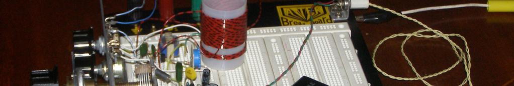
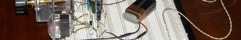
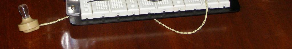
2 control has been included in the circuit. A high-impedance crystal or ceramic piezoelectric earphone should be used for listening. Alternatively, an audio output transformer that will match low-impedance magnetic earpieces to 5kohms 7kohms may be connected to Q 3 s collector through a 0.47-uF capacitor. Highimpedance 2k-ohms magnetic headphones do not require a transformer. They can be connected directly to Q 3 s output using the said capacitor. Components C 9, R 11, R 12, germanium diode 1N34 (it can be any other germanium detector type), Q 4, the S-meter and the high-efficiency blue LED form a pseudo tuning-indicator circuit which gives an idea of the available audio level at the output of Q 3 after demodulation. We have then a visual relative indication of the tuning action of our circuit. Solderless breadboards known as protoboards show parasitic capacitances of about 3pF between adjacent connection lines. Hence, excercising the builder some minimum of care in point-to-point connections on the layout, the protoboard will lend itself as an acceptable breadboarding material for the testing of simple receivers, such as the one dealt with here. The author has tested on a breadboard of this sort the design herein described, with an additional aluminum ground plane fixed underneath. This metallic plane is fundamental for reducing hand-capacitance effects when adjusting the variable tuning capacitor C 1. In order to avoid ground loops it is advisable to connect the circuit s common ground to the plane at a single point. It is very important to use short connecting wires between components. -2-

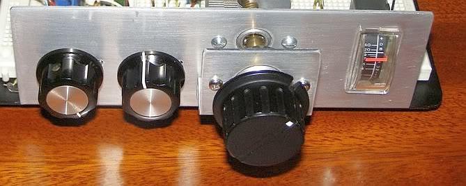
3 Shortwave frequencies are nicely tuned by the receiver using a random-wire outdoor antenna and a capacitive ground of the type described in Fig.1 above. It is not absolutely necessary to resort to a cold water pipe connection, nor to use a metallic rod buried in the soil out there in the garden. At this point we should avoid any possible confusion between the aluminum ground plane beneath the protoboard and the external capacitive ground connection via a 30cm x 30cm aluminum metal sheet thrown on the floor under the workbench. These are two different issues. Unwanted interference produced by FM or TV stations is easily blocked connecting a small 10-uH RF choke between the antenna lead-in and the receiver. The author uses two of these chokes in series, which gives further better results. It is best for the RF choke to have low distributed capacitance, so that VHF FM or TV signal leak-in problems can be avoided. Following, some pictures of the prototype are shown. The RF attenuator R 13, the reaction or regeneration control R 9, the variable tuning capacitor C 1 and the S-meter are mounted on an aluminum panel fixed to the protoboard s ground plane. It is important to have a good mechanical and electrical joint between the aluminum panel and the ground plane. Views of the completed receiver: -3-

4 -4-


5 -5- Ramón Vargas Patrón Lima-Peru, South America March 24 th 2010
Design of a Regenerative Receiver for the Short-Wave Bands A Tutorial and Design Guide for Experimental Work. Part I
 Design of a Regenerative Receiver for the Short-Wave Bands A Tutorial and Design Guide for Experimental Work Part I Ramón Vargas Patrón rvargas@inictel-uni.edu.pe INICTEL-UNI Regenerative Receivers remain
A GOOD REGENERATIVE RECEIVER WITH SIMPLE FINE TUNING (2008)
") A GOOD REGENERATIVE RECEIVER WITH SIMPLE FINE TUNING (2008) A good SSB-CW-AM regenerative receiver with a fine tuning by moving the wooden stick with a grounded piece of PCB towards the coil. A good regenerative
A GOOD REGENERATIVE RECEIVER WITH SIMPLE FINE TUNING (2008) A good SSB-CW-AM regenerative receiver with a fine tuning by moving the wooden stick with a grounded piece of PCB towards the coil. A good regenerative
Oscillations and Regenerative Amplification using Negative Resistance Devices
 Oscillations and Regenerative Amplification using Negative Resistance Devices Ramon Vargas Patron rvargas@inictel.gob.pe INICTEL The usual procedure for the production of sustained oscillations in tuned
Building the Sawdust Regenerative Receiver
 Building the Sawdust Regenerative Receiver Introduction The Sawdust is a super regenerative receiver using the basic Armstrong design architecture. The receiver uses one toroidal transformer to provide
EE301 ELECTRONIC CIRCUITS CHAPTER 2 : OSCILLATORS. Lecturer : Engr. Muhammad Muizz Bin Mohd Nawawi
 EE301 ELECTRONIC CIRCUITS CHAPTER 2 : OSCILLATORS Lecturer : Engr. Muhammad Muizz Bin Mohd Nawawi 2.1 INTRODUCTION An electronic circuit which is designed to generate a periodic waveform continuously at
HOMEBREW Q-MULTIPLIER
 HOMEBREW Q-MULTIPLIER This circuit can boost the signal strength in your receiver by 1 or 2 S-units, giving approximately 10 db gain. A Q-multiplier amplifies the Q of the first IF transformer so that
Ozark Patrol Assembly Manual
 Ozark Patrol Assembly Manual Copyright 2014 David Cripe NM0S The 4 State QRP Group Thank you for purchasing a Ozark Patrol kit. We hope you will enjoy building it and and find it a fun addition to your
RadiØKit Μ CW HAM RADIO TRANSCEIVER KIT. Assembly and operating manual
 RadiØKit-120 20Μ CW HAM RADIO TRANSCEIVER KIT Assembly and operating manual Boreiou Ipirou 78 Kolonos Athens- Greece - 10444 Tel: 210.5150527 210.5132673 www.freebytes.com Thank you for buying RadiØKit-1,
Building the Sawdust Regenerative Receiver
 Building the Sawdust Regenerative Receiver Introduction The Sawdust is a super regenerative receiver using the basic Armstrong design architecture. The receiver uses one toroidal transformer to provide
Radio Receivers. Al Penney VO1NO
 Radio Receivers Al Penney VO1NO Role of the Receiver The Antenna must capture the radio wave. The desired frequency must be selected from all the EM waves captured by the antenna. The selected signal is
Amateur Radio Examination EXAMINATION PAPER No. 275 MARKER S COPY
 01-6-(d) An Amateur Station is quoted in the regulations as a station: a for training new radio operators b using amateur equipment for commercial purposes c for public emergency purposes d in the Amateur
The Amazing All-Band Receiver
 The Amazing All-Band Receiver The Amazing All-Band Receiver is basically a diode detector followed by a high-gain audio amplifier. The detector uses a biased Schottky diode for excellent sensitivity and
Module 8 Theory. dbs AM Detector Ring Modulator Receiver Chain. Functional Blocks Parameters. IRTS Region 4
 Module 8 Theory dbs AM Detector Ring Modulator Receiver Chain Functional Blocks Parameters Decibel (db) The term db or decibel is a relative unit of measurement used frequently in electronic communications
Radio Receivers. Al Penney VO1NO
 Radio Receivers Role of the Receiver The Antenna must capture the radio wave. The desired frequency must be selected from all the EM waves captured by the antenna. The selected signal is usually very weak
Chapter 6. FM Circuits
 Chapter 6 FM Circuits Topics Covered 6-1: Frequency Modulators 6-2: Frequency Demodulators Objectives You should be able to: Explain the operation of an FM modulators and demodulators. Compare and contrast;
Technician License Course Chapter 3 Types of Radios and Radio Circuits. Module 7
 Technician License Course Chapter 3 Types of Radios and Radio Circuits Module 7 Radio Block Diagrams Radio Circuits can be shown as functional blocks connected together. Knowing the description of common
1. What is the unit of electromotive force? (a) volt (b) ampere (c) watt (d) ohm. 2. The resonant frequency of a tuned (LRC) circuit is given by
 volt (b) ampere (c) watt (d) ohm. 2. The resonant frequency of a tuned (LRC) circuit is given by") Department of Examinations, Sri Lanka EXAMINATION FOR THE AMATEUR RADIO OPERATORS CERTIFICATE OF PROFICIENCY ISSUED BY THE DIRECTOR GENERAL OF TELECOMMUNICATIONS, SRI LANKA 2004 (NOVICE CLASS) Basic Electricity,
Department of Examinations, Sri Lanka EXAMINATION FOR THE AMATEUR RADIO OPERATORS CERTIFICATE OF PROFICIENCY ISSUED BY THE DIRECTOR GENERAL OF TELECOMMUNICATIONS, SRI LANKA 2004 (NOVICE CLASS) Basic Electricity,
GARC Regenerative radio night.
 GARC Regenerative radio night. A follow on project from the highly successful Crystal set night. Aim. It is hoped that we can continue on from the very high level of interest and participation that occurred
About Q. About Q, Xtal Set Society, Inc
 About Q, Xtal Set Society, Inc In the crystal radio hobby and in electronics in general Q can refer to a number of things: the Q of a coil, the Q of a circuit, the quality factor of some item, or the label
Lecture # 12 Oscillators (LC Circuits)
") December 2014 Benha University Faculty of Engineering at Shoubra ECE-312 Electronic Circuits (A) Lecture # 12 Oscillators (LC Circuits) Instructor: Dr. Ahmad El-Banna Agenda The Colpitts Oscillator The
December 2014 Benha University Faculty of Engineering at Shoubra ECE-312 Electronic Circuits (A) Lecture # 12 Oscillators (LC Circuits) Instructor: Dr. Ahmad El-Banna Agenda The Colpitts Oscillator The
Simple SWL HF- VHF Receiver
 ANTENTOP- 01-2007, # 009 Simple SWL HF- VHF Receiver From the book DX Reception (by Igor Grigorov (RK3ZK), Belgorod, 1994), pp.:76-81. (Article published with inessential cutting) See ANTENTOP- 01-2007,
for use Supervisor: on chip
 Local Oscillator for use in FM Broadcast Radio Receiver ETI 041: Radio Project Supervisor: Göran Jönsson Student: Yelin Wang and Hao Cai Master Program: System on chip Lund University Abstract Oscillator
GRID DIP METER DESIGN
 GRID DIP METER DESIGN BY G0CWA MAY 2013 This, my next offering of test equipment is an exceptionally useful item of test equipment with many uses, some are listed below. To coin a phrase given to me by
High performance low power mixer FM IF system
 DESCRIPTION The is a high performance monolithic low-power FM IF system incorporating a mixer/oscillator, two limiting intermediate frequency amplifiers, quadrature detector, muting, logarithmic received
The New England Radio Discussion Society electronics course (Phase 4, cont d) Introduction to receivers
 Introduction to receivers") The New England Radio Discussion Society electronics course (Phase 4, cont d) Introduction to receivers AI2Q April 2017 REVIEW: a VFO, phase-locked loop (PLL), or direct digital synthesizer (DDS), can
The New England Radio Discussion Society electronics course (Phase 4, cont d) Introduction to receivers AI2Q April 2017 REVIEW: a VFO, phase-locked loop (PLL), or direct digital synthesizer (DDS), can
EXPERIMENT #2 CARRIER OSCILLATOR
 EXPERIMENT #2 CARRIER OSCILLATOR INTRODUCTION: The oscillator is usually the first stage of any transmitter. Its job is to create a radio-frequency carrier that can be amplified and modulated before being
Crystal Oscillators and Circuits
 Crystal Oscillators and Circuits It is often required to produce a signal whose frequency or pulse rate is very stable and exactly known. This is important in any application where anything to do with
Norfolk Amateur Radio Club
 Norfolk Amateur Radio Club The Transmitter & Transmitter Interference Nick M0HGU & Steve G3PND Plan for the Day The Transmitter Introduction, Block diagrams Oscillators, Buffers & Multipliers Modulation
Application Note Receivers MLX71120/21 With LNA1-SAW-LNA2 configuration
 Designing with MLX71120 and MLX71121 receivers using a SAW filter between LNA1 and LNA2 Scope Many receiver applications, especially those for automotive keyless entry systems require good sensitivity
THE 1956 ZENITH ROYAL 500 TRANSISTOR OWL S EYES RADIO.
 THE 1956 ZENITH ROYAL 500 TRANSISTOR OWL S EYES RADIO. Dr. H. Holden. Feb. 2018. Introduction: The Zenith Royal 500 radio appeared in 1956, two years later than the Regency TR1 which was the first commercial
The ROSE 80 CW Transceiver (Part 1 of 3)
") Build a 5 watt, 80 meter QRP CW Transceiver!!! Page 1 of 10 The ROSE 80 CW Transceiver (Part 1 of 3) Build a 5 watt, 80 meter QRP CW Transceiver!!! (Designed by N1HFX) A great deal of interest has been
Build a 5 watt, 80 meter QRP CW Transceiver!!! Page 1 of 10 The ROSE 80 CW Transceiver (Part 1 of 3) Build a 5 watt, 80 meter QRP CW Transceiver!!! (Designed by N1HFX) A great deal of interest has been
Amateur Wireless Station Operators License Exam
 Amateur Wireless Station Operators License Exam Study material 2017 South India Amateur Radio Society, Chennai CHAPTER 5 1 Chapter 5 Amateur Wireless Station Operators License Exam Study Material Chapter
Low voltage high performance mixer FM IF system
 DESCRIPTION The is a low voltage high performance monolithic FM IF system incorporating a mixer/oscillator, two limiting intermediate frequency amplifiers, quadrature detector, logarithmic received signal
EKB Shortwave Receiver made in GDR by VEB Funktechnik Dabendorf
 All pictures hb9aik - vk2ani EKB Shortwave Receiver made in GDR by VEB Funktechnik Dabendorf Restauration of the Czech Model R5 with AC P.S. Description & Picture Gallery Page 1/10 Preface: The Small Print
Radio Merit Badge Boy Scouts of America
 Radio Merit Badge Boy Scouts of America Module 2 Electronics, Safety & Careers BSA National Radio Scouting Committee2012 Class Format Three modules any order Module 1 Intro To Radio Module 2 Electronic
ANALOG COMMUNICATION
 ANALOG COMMUNICATION TRAINING LAB Analog Communication Training Lab consists of six kits, one each for Modulation (ACL-01), Demodulation (ACL-02), Modulation (ACL-03), Demodulation (ACL-04), Noise power
MAINTENANCE MANUAL TRANSMITTER/RECEIVER BOARD CMN-234A/B FOR MLSU141 & MLSU241 UHF MOBILE RADIO TABLE OF CONTENTS
 MAINTENANCE MANUAL TRANSMITTER/RECEIVER BOARD CMN-234A/B FOR MLSU141 & MLSU241 UHF MOBILE RADIO TABLE OF CONTENTS DESCRIPTION... 2 CIRCUIT ANALYSIS... 2 TRANSMITTER... 2 9-Voft Regulator... 2 Exciter...
The Aleph 5 is a stereo 60 watt audio power amplifier which operates in single-ended class A mode.
 Pass Laboratories Aleph 5 Service Manual Rev 0 9/20/96 Aleph 5 Service Manual. The Aleph 5 is a stereo 60 watt audio power amplifier which operates in single-ended class A mode. The Aleph 5 has only two
S-Pixie QRP Kit. Student Manual. Revision V 1-0
 S-Pixie QRP Kit Student Manual Revision V 1-0 Introduction The Pixie 2 is a small, versatile radio transceiver that is very popular with QRP (low power) amateur radio operators the world over. It reflects
SPECIFICATIONS: Subcarrier Frequency 5.5MHz adjustable, FM Modulated +/- 50KHz. 2nd 11MHz >40dB down from 5.5MHz
 Mini-kits AUDIO / SUBCARRIER KIT EME75 Version4 SPECIFICATIONS: Subcarrier Frequency 5.5MHz adjustable, FM Modulated +/- 50KHz Subcarrier Output 1.5v p-p Output @ 5.5MHz DESCRIPTION & FEATURES: The Notes
TDA7000 for narrowband FM reception
 TDA7 for narrowband FM reception Author: Author: W.V. Dooremolen INTRODUCTION Today s cordless telephone sets make use of duplex communication with carrier frequencies of about.7mhz and 49MHz. In the base
V. 3. Assembly Guide. ShortWave Receiver Kit Double Super 10.7Mhz /455Khz SSB/CW/AM 5.9 Mhz to 8.1 Nominal. SW-Receiver
 Assembly Guide V. 3 JUNIOR 1 ShortWave Receiver Kit Double Super 10.7Mhz /455Khz SSB/CW/AM 5.9 Mhz to 8.1 Nominal SW-Receiver Table of contents PAGE TITLE PAGE JUNIOR 1 General Description I1 JUNIOR 1
S Pixie QRP Kit User Manual. Welcome to visit the home page to obtain the latest data. 1 / 24. Revision V160515
 S-Pixie QRP Kit User Manual Revision V160515 Welcome to visit the home page www.lxqqfy.com to obtain the latest data. 1 / 24 1. Introduction PIXIE is a very small volume of simple 40 meter band micro-power
Parallel Port Relay Interface
 Parallel Port Relay Interface Below are three examples of controlling a relay from the PC's parallel printer port (LPT1 or LPT2). Figure A shows a solid state relay controlled by one of the parallel port
REDSUN PF2100 PLL RADIO OPERATING MANUAL
 REDSUN PF2100 PLL RADIO OPERATING MANUAL TRANSLATED BY LIYPN ALL RIGHTS RESERVED JUNE 2006 (We are the copyright holder of this manual in English. Please do NOT distribute this manual in any form nor post
CHAPTER 13 TRANSMITTERS AND RECEIVERS
 CHAPTER 13 TRANSMITTERS AND RECEIVERS Frequency Modulation (FM) Receiver Frequency Modulation (FM) Receiver FREQUENCY MODULATION (FM) RECEIVER Superheterodyne Receiver Heterodyning The word heterodyne
VHF Super-Regenerative Receiver
 VHF Super-Regenerative Receiver I have started straight with the circuit out of the ARRL handbook, by Charles Kitchen N1TEV. I didn't have a 6v8 zener, or a few other part values, so I had to substitute
LBI-30398N. MAINTENANCE MANUAL MHz PHASE LOCK LOOP EXCITER 19D423249G1 & G2 DESCRIPTION TABLE OF CONTENTS. Page. DESCRIPTION...
 MAINTENANCE MANUAL 138-174 MHz PHASE LOCK LOOP EXCITER 19D423249G1 & G2 LBI-30398N TABLE OF CONTENTS DESCRIPTION...Front Cover CIRCUIT ANALYSIS... 1 MODIFICATION INSTRUCTIONS... 4 PARTS LIST AND PRODUCTION
LNB and its ham radio usage
 http://ea4eoz.blogspot.gr/2012/09/lnb-and-its-ham-radio-usage.html LNB and its ham radio usage The letters LNB means Low Noise Block, but we must call it LNC, this is Low Noise Converter, because a LNB
How to solve an EMC and harmonic mixing problem in a Yeasu Musen FRG-7 communications receiver (0 30 MHz general coverage, AM/SSB/CW).
.") How to solve an EMC and harmonic mixing problem in a Yeasu Musen FRG-7 communications receiver (0 30 MHz general coverage, AM/SSB/CW). Investigated by: ir. W.J. Vogel. Date of investigation: 24 November
How to solve an EMC and harmonic mixing problem in a Yeasu Musen FRG-7 communications receiver (0 30 MHz general coverage, AM/SSB/CW). Investigated by: ir. W.J. Vogel. Date of investigation: 24 November
No.01 Transistor Tester
 Blocks used Tester Circuits No.01 Transistor Tester Electronic components may break down if used or connected improperly. Let s start with a simple tester circuit project designed to teach you how to handle
The Aleph 2 is a monoblock 100 watt audio power amplifier which operates in single-ended class A mode.
 Pass Laboratories Aleph 2 Service Manual Rev 0 2/1/96 Aleph 2 Service Manual. The Aleph 2 is a monoblock 100 watt audio power amplifier which operates in single-ended class A mode. The Aleph 2 has only
Figure 2 shows the actual schematic for the power supply and one channel.
 Pass Laboratories Aleph 3 Service Manual rev 0 2/1/96 Aleph 3 Service Manual. The Aleph 3 is a stereo 30 watt per channel audio power amplifier which operates in single-ended class A mode. The Aleph 3
HF Receivers, Part 2
 HF Receivers, Part 2 Superhet building blocks: AM, SSB/CW, FM receivers Adam Farson VA7OJ View an excellent tutorial on receivers NSARC HF Operators HF Receivers 2 1 The RF Amplifier (Preamp)! Typical
Introduction Introduction to radio frequencies p. 3 What are the 'radio frequencies'? p. 3 Why are radio frequencies different? p.
 Foreword p. xi Preface p. xiii Introduction Introduction to radio frequencies p. 3 What are the 'radio frequencies'? p. 3 Why are radio frequencies different? p. 3 What this book covers p. 3 Signals and
Maintenance Manual TRANSMITTER/RECEIVER BOARD CMN-233 FOR MLSH041
 Maintenance Manual TRANSMITTER/RECEIVER BOARD CMN-233 FOR MLSH041 TABLE OF CONTENTS Page DESCRIPTION... 2 CIRCUIT ANALYSIS... 2 Transmitter... 2 9-volt Regulator... 2 Exciter... 2 40-Watt PA... 2 Antenna
ERICSSONZ LBI-30398P. MAINTENANCE MANUAL MHz PHASE LOCKED LOOP EXCITER 19D423249G1 & G2 DESCRIPTION TABLE OF CONTENTS
 MAINTENANCE MANUAL 138-174 MHz PHASE LOCKED LOOP EXCITER 19D423249G1 & G2 TABLE OF CONTENTS Page DESCRIPTION... Front Cover CIRCUIT ANALYSIS...1 MODIFICATION INSTRUCTIONS...4 PARTS LIST...5 PRODUCTION
Amateur Radio Examination EXAMINATION PAPER No. 276 MARKER S COPY
 01-3-(a) The Amateur Service in New Zealand is administered through this prime document: a the New Zealand Radiocommunications Regulations b the Broadcasting Act c the Telecommunications Act d the Radio
AM Generation High Level Low Level
 AM Generation High Level Low Level Low-level generation In modern radio systems, modulated signals are generated via digital signal processing (DSP). With DSP many types of AM modulation are possible with
I'm guessing this is what has made it so no one else could get the circuit to work, I hope this helps.
 Incase I did not mention this else where, the basis of my system to provide random audio bits which the spirits can use to form their voices. The audio bits are from randomly tuning a voltage tunable AM
MISCELLANEOUS. Figure 1.
 Reading 41 Ron Bertrand VK2DQ http://www.radioelectronicschool.com MISCELLANEOUS The purpose of this reading is to catch anything that may have slipped through the previous forty readings or just does
ZN414Z, ZN415E, ZN416E AM RADIO RECEIVERS
 GEC PLESSEY [SEMICONDUCTORS ZN414Z, ZN415E, ZN416E AM RADIO RECEIVERS FEATURES Single cell operation (1.1 to 1.6 volt, operating range) Low current consumption 150kHz to 3MHz frequency range (i.e. full
Applications Note RF Transmitter and Antenna Design Hints
 This application note covers the TH7107,TH71071,TH71072,TH7108,TH71081,TH72011,TH72031,TH7204 Single Frequency Transmitters. These transmitters have different features and cover different bands but they
Crystal Radio Circuits
 Crystal Radio Circuits Simple Crystal Radio One-Transistor Amplifier/Detector TL431 Crystal Radio Amplifier Crystal Radio RF Amplifier Very High Gain Crystal Earphone Amplifier Simple Two-transistor Radio
Expect to be successful, expect to be liked,
 Thought of the Day Expect to be successful, expect to be liked, expect to be popular everywhere you go. Oscillators 1 Oscillators D.C. Kulshreshtha Oscillators 2 Need of an Oscillator An oscillator circuit
Low-voltage mixer FM IF system
 DESCRIPTION The is a low-voltage monolithic FM IF system incorporating a mixer/oscillator, two limiting intermediate frequency amplifiers, quadrature detector, logarithmic received signal strength indicator
Transmitters and receivers
 Chapter 3 Transmitters and receivers Transmitters and receivers are used extensively in aircraft communication and navigation systems. In conjunction with one ore more antennas, they are responsible for
Block Diagrams Definitions & Safety Lesson 3 From: Emergency Management Ontario
 Block Diagrams Definitions & Safety Regulated Power Supply Power supply A power supply (sometimes known as a power supply unit or PSU) is a device or system that supplies electrical or other types of energy
2m Weak Signal Sources January 2018
 2m Weak Signal Sources January 2018 Rick Campbell This white paper describes a set of signal sources at power levels from -30dBm to +12dBm in the 144 MHz amateur radio band. All are legal for direct connection
A 75-Watt Transmitter for 3 Bands Simplified Shielding and Filtering for TVI BY DONALD H. MIX, W1TS ARRL Handbook 1953 and QST, October 1951
 A 75-Watt Transmitter for 3 Bands Simplified Shielding and Filtering for TVI BY DONALD H. MIX, W1TS ARRL Handbook 1953 and QST, October 1951 The transmitter shown in the photographs is a 3-stage 75-watt
4/30/2012. General Class Element 3 Course Presentation. Circuit CoCircuit Componentsmponents. Subelement G6. 3 Exam Questions, 3 Groups
 General Class Element 3 Course Presentation ti ELEMENT 3 SUB ELEMENTS General Licensing Class Subelement G6 Circuit Components 3 Exam Questions, 3 Groups G1 Commission s Rules G2 Operating Procedures G3
Step by Step Building PJ meter ARDF Receiver Kit. CRKITS.COM August 5, 2013
 Step by Step Building PJ-80 80-meter ARDF Receiver Kit CRKITS.COM August 5, 2013 What is ARDF? ARDF is the abbreviation of Amateur Radio Direction Finding, or so called Fox Hunting. If you are looking
EURO QUARTZ TECHNICAL NOTES. Crystal Theory. Page 1 of 8. Introduction. The Crystal Equivalent Circuit. Series or Parallel? Crystal Equivalent Circuit
 Crystal Theory Page of 8 Introduction If you are an engineer mainly working with digital devices these notes should reacquaint you with a little analogue theory. The treatment is non-mathematical, concentrating
Cascode Oscillation in Audio Amplifiers
 Cascode Oscillation in Audio Amplifiers About 80mV pk-pk oscillation at ~182MHz was noted on the oscilloscope during routine debugging of a cascoded front end circuit for a high power balanced symmetrical
Elecraft EC1 Design Contest Entry
 Elecraft EC1 Design Contest Entry The following is an Elecraft EC1 design contest entry from Joe Loritz, N9ZIA. Design Overview This design is a low cost, easy to homebrew, 100-900 MHz antenna analyzer.
Topic Advanced Radio Receivers. Explain that an RF amplifier can be used to improve sensitivity;
 Learning Objectives: At the end of this topic you will be able to; Explain that an RF amplifier can be used to improve sensitivity; Explain that a superheterodyne receiver offers improved selectivity and
Interference & Suppression Page 59
 INTERFERENCE Interference & Suppression Page 59 Front-End Overload, Cross-Modulation What is meant by receiver overload? Interference caused by strong signals from a nearby transmitter What is one way
BEST BMET CBET STUDY GUIDE MODULE ONE
 BEST BMET CBET STUDY GUIDE MODULE ONE 1 OCTOBER, 2008 1. The phase relation for pure capacitance is a. current leads voltage by 90 degrees b. current leads voltage by 180 degrees c. current lags voltage
A Pretty Good Crystal Set Mark II
 A Pretty Good Crystal Set Mark II By Al Klase, N3FRQ, http://www.skywaves.ar88.net/ This is a revised version of the original New Jersey Antique Radio Club PGXS with minor changes to improve performance
N3ZI Kits General Coverage Receiver, Assembly & Operations Manual (For Jun 2011 PCB ) Version 3.33, Jan 2012
 Version 3.33, Jan 2012") N3ZI Kits General Coverage Receiver, Assembly & Operations Manual (For Jun 2011 PCB ) Version 3.33, Jan 2012 Thank you for purchasing my general coverage receiver kit. You can use the photo above as a
N3ZI Kits General Coverage Receiver, Assembly & Operations Manual (For Jun 2011 PCB ) Version 3.33, Jan 2012 Thank you for purchasing my general coverage receiver kit. You can use the photo above as a
SA625 High performance low power mixer FM IF system with high-speed RSSI
 RF COMMUNICATIONS PRODUCTS High performance low power mixer FM IF system Replaces data of November 3, 1992 IC17 Data Handbook 1997 Nov 07 Philips Semiconductors DESCRIPTION The is pin-to-pin compatible
The 6LE8 One Tube Broadcaster
 The 6LE8 One Tube Broadcaster Introduction The purpose of this broadcaster is to transmit your favorite music to every AM radio in your home. The transmitting power is so low that it should not bother
TBA120 Series & SN FM Demodulator IC
 TBA120 Series & SN76660 - FM Demodulator IC The TBA120 Series ICs provide a high-gain limiting IF amplifier and a quadrature coincidence detector in one package. These ICs are primarily intended for extraction
1665 MHz Radio Astronomy Receiver Part 1. Kevin Murphy ZL1UJG Tom Bevan ZL1THG Robin Holdsworth ZL1IC
 1665 MHz Radio Astronomy Receiver 2006 Part 1 Kevin Murphy ZL1UJG Tom Bevan ZL1THG Robin Holdsworth ZL1IC 1 1665 MHz Radio Astronomy Receiver July 2006 Kevin Murphy Tom Bevan Robin Holdsworth ZL1UJG ZL1THG
A 40m Direct Conversion Receiver project to upgrade from ZR to ZS
 A 40m Direct Conversion Receiver project to upgrade from ZR to ZS Hannes Coetzee, ZS6BZP, B.Eng Elektronic (Pretoria) A simple receiver with a low component count is described for the 40m Amateur band.
Low Pass Filter (rev 5) for single and 2-Pallet HF Amplifiers The filter sections on this board differ from the web article, and offer some
 for single and 2-Pallet HF Amplifiers The filter sections on this board differ from the web article, and offer some") The filter sections on this board differ from the web article, and offer some improvement in performance, including raising the maximum power handling capacity. The most significant changes were to the
The filter sections on this board differ from the web article, and offer some improvement in performance, including raising the maximum power handling capacity. The most significant changes were to the
FM / TV front end BA4424N. Audio ICs
 FM / TV front end The is a monolithic IC designed for FM front end use. It consists of an RF amplifier circuit, mixer circuit, local oscillation circuit, IF buffer amplifier, and a variable capacitor-diode
Lab 4. Crystal Oscillator
 Lab 4. Crystal Oscillator Modeling the Piezo Electric Quartz Crystal Most oscillators employed for RF and microwave applications use a resonator to set the frequency of oscillation. It is desirable to
ITT Technical Institute. ET275 Electronic Communications Systems I Onsite Course SYLLABUS
 ITT Technical Institute ET275 Electronic Communications Systems I Onsite Course SYLLABUS Credit hours: 4 Contact/Instructional hours: 50 (30 Theory Hours, 20 Lab Hours) Prerequisite(s) and/or Corequisite(s):
A Low Noise Amplifier with HF Selectivity
 A Low Noise Amplifier with HF Selectivity Johan Karlsson Mikael Grudd Radio project 2008 Department of Electrical and Information Technology Lund University Supervisor: Göran Jönsson Abstract This report
ET275P Electronic Communications Systems I [Onsite]
![ET275P Electronic Communications Systems I [Onsite]](/thumbs/85/92760903.jpg "ET275P Electronic Communications Systems I [Onsite]") ET275P Electronic Communications Systems I [Onsite] Course Description: In this course, several methods of signal transmission and reception are covered, including such techniques as mixing, modulating
ET275P Electronic Communications Systems I [Onsite] Course Description: In this course, several methods of signal transmission and reception are covered, including such techniques as mixing, modulating
EE 318 Electronic Design Lab. Hi-fi Audio Transmitter from first principles
 EE 318 Electronic Design Lab Hi-fi Audio Transmitter from first principles Supervised by Prof. Jayanta Mukherjee Prof. Dipankar Prof. L. Subramaniam By Group-9 Vipul Chaudhary (08d07039) Vineet Raj (08d07040)
RADIO AMATEUR EXAM GENERAL CLASS
 RAE-Lessons by 4S7VJ 1 CHAPTER-5 RADIO AMATEUR EXAM GENERAL CLASS By 4S7VJ 5.1 RECEIVER The main purpose of a radio receiver is receive RF signal and convert to AF signal or get the audio signal out from
RF Energy Harvesting for Low Power Electronic Devices
 RF Energy Harvesting for Low Power Electronic Devices Student project Kaloyan A. Mihaylov Abstract Different methods for RF energy harvesting from radio transmitters with working frequency of up to 108
Chapter.8: Oscillators
 Chapter.8: Oscillators Objectives: To understand The basic operation of an Oscillator the working of low frequency oscillators RC phase shift oscillator Wien bridge Oscillator the working of tuned oscillator
DUAL CONVERSION AM RECEIVER
 Order this document by MC3030/D DUAL CONVERSION AM RECEIVER The MC3030 is a dual conversion AM receiver designed for car radio applications. It includes a high dynamic range first mixer, local oscillator,
VHF/UHF Dual Band J-Pole. By: Ed Fong WB6IQN
 VHF/UHF Dual Band J-Pole By: Ed Fong WB6IQN email: edison_fong@hotmail.com ARRL VHF/UHF Antenna Classics ARRL Vol. 8 Antenna Compendium ARRL Vol. 3 Antenna Compendium QST March 2007 QST February 2003 QST
Block Diagrams Definitions & Safety
 Block Diagrams Definitions & Safety Regulated Power Supply Power supply A power supply (sometimes known as a power supply unit or PSU) is a device or system that supplies electrical or other types of energy
Table of Contents Lesson One Lesson Two Lesson Three Lesson Four Lesson Five PREVIEW COPY
 Oscillators Table of Contents Lesson One Lesson Two Lesson Three Introduction to Oscillators...3 Flip-Flops...19 Logic Clocks...37 Lesson Four Filters and Waveforms...53 Lesson Five Troubleshooting Oscillators...69
MK LOW PHASE NOISE T1/E1 CLOCK GENERATOR. Features. Description. Block Diagram DATASHEET. Pullable Crystal
 DATASHEET LOW PHASE NOISE T1/E1 CLOCK ENERATOR MK1581-01 Description The MK1581-01 provides synchronization and timing control for T1 and E1 based network access or multitrunk telecommunication systems.