It s Logical! Technical Newsletter. Logic, the basics you need to know
|
|
|
- Fay Pitts
- 5 years ago
- Views:
Transcription


1 Technical Newsletter V O L U M E I, I S S U E 2 It s Logical! The first newsletter issue received such a great feedback that it was decided to expand the distribution to an international level. It is great to hear that the content of this newsletter is helpful while specifying Biamp Systems products, programming Open Architecture DSP s or troubleshooting installations. This month s topic is about the use of logic in Audia and Nexia. The Biamp support team gets a lot of inquiries on the topic and this brief technical overview will hopefully help you on how to design with logic in mind. The intention is not to give you an electronic tutorial on logic but rather focus on the basic knowledge required to use logic within an Audia/Nexia design. As for advanced programmers, a couple of tips and tricks are also included in this technical newsletter. Remember that we always look forward to hearing your comments, so please feel free to contact the Newsletter editor (Tony) for suggestions you may have. If there are others within your office who may be interested by the content of this Newsletter, let us know and we will add them to the distribution list. Biamp Technical Support Team M A Y I S S U E Logic, the basics you need to know Binary logic is easy! There are only 2 logic states: High (1) and Low (0). The trick to make full use of logic is to understand logic gates: the basic component in digital electronic. Logic gates are used to create digital circuitry. Each logic gate has a truth table that dictates the output state depending on the input. Going over each logic gate (6 in total in Audia/Nexia) and explaining their respective truth tables would not be of much use for beginners in the field of logic. Instead, it is more important to focus on understanding well the basic logic gates: AND, OR and NOT. Then look in the application note Logic control in Audia and Nexia software for the truth table of each gate whenever required. AND Gate - The output is high when both inputs are high, otherwise the output is low Application Example: 2 toggle switches are connected to logic inputs of a logic box/vcb and shall only trigger a remote preset when Switch 1 AND Switch 2 are closed. Use an AND gate to combine both logic signals. (See example below) OR Gate - The output is high if either or both inputs are high, otherwise the output is low Application Example: 2 toggle switches shall trigger the remote preset if either switch is closed. I.e. Switch 1 OR Switch 2 would trigger the preset. Use an OR gate to combine both logic signals. (See example below) NOT Gate - also referred as Inverter reverses the logic state: Low input becomes High output, High input becomes Low output Application Example: If the switch is closed, recall preset 2, if it s open then recall preset 1. (See Example below) FLIP FLOP - Maintains logic state until a input pulse triggers a change to the opposite state. i.e: low to high transition causes logic output to toggle from its present state to the opposite state. Application Example: A momentary switch connected to a flip-flop will behave like a toggle switch. Every contact closure will change the state of the flip flop to its opposite state. LOGIC BOX/VCB I/O - Logic I/O of a Logic Box/Voltage Control Box are open collectors with internal pull up resistors., I.e. both logic inputs and outputs are normally high. While activating the logic input (contact closure), its input will be seen as Low state (0) inside by the DSP. This may explain why, in the following examples, a NOT gate was used to reverse the state of the logic box/vcb inputs (i.e. contact closure will trigger preset). NOR (NOT - OR): The output is high when both inputs are low, otherwise the output is low. It is the inverse behavior of an OR gate. NAND (NOT - AND)- The output is low when both inputs are high, otherwise the output is high.. It is the inverse behavior of an AND gate. AND gate OR gate NOT gate Flip Flop

2 PAGE 2 Typical logic applications Let s now move on to applying previously described logic concepts to an Audia/Nexia design. As a quick reminder, the universal connectivity structure of a processing block in Audia/Nexia software will always be: Logic inputs on the top and a logic outputs on the bottom of the block Audio inputs on the left side and audio outputs on the right side of the block The following chart summarizes a few of the typical applications for logic enabled DSP blocks. Please refer to the application note Using Logic Control in Audia and Nexia for more information on each DSP block. Device Logic behavior Typical Applications Logic output indicates the state of the gate Trigger remote presets when a microphone becomes active. Logic High (1): Microphone gate ON Trigger command string to control 3 rd party devices such as video router Logic Low(0): Microphone gate OFF or PTZ camera controller via RS232 Trigger camera position through a logic box Auto Mixer Trigger microphone active indicator on davinci, confidence light at the microphone or a tally light on a custom LED panel Room Combiner Ducker Remote Preset Level Inc/Dec Mute Control Command String Event Scheduler Logic input controls the state of the partition inside the room combiner Logic High(1): Partition is open Logic Low(0): Partition is closed Logic input provides manual override of the ducker Logic High(1): Duck Program audio Low(0): Un-duck Program Audio Logic output indicates state of the ducker Logic input triggers preset recall Transition Low to High(1): Triggers preset Transition High to Low(0): N/A Logic input controls increment and decrement of level, if ramping is enabled: Logic High(1) on + node: Ramps up level Logic High(1) on - node: Ramps down level Note: If ramping is disabled, transition low to high increments/decrements level by single step Logic input controls muting Logic High(1): Mute audio Logic Low(0): Un-mute audio Logic input controls send of command string on the RS232 port Transition Low to High(1): Send command Transition High to Low(0): N/A Logic input controls enable/disable of event scheduling: Logic High (1): Event scheduler disabled Logic Low(0): Event scheduler enabled Logic output normally low changes to logic high for 250ms at schedule event time Control the state of the room combiner with partition sensors or other contact closures connected to a logic box Control the state of partition from davinci with the help of logic states Manual override of the ducking Logic output may be used to trigger other actions. E.g.: for emergency announcement pages, the ducker may trigger mute of all program audio until the user manually overrides the system back to its normal state. Trigger chimes after each announcement Presets may be recalled by external/internal logic trigger Connect Select8 to a remote preset to control recall of preset from the field Volume control from momentary switches custom control panel Control Fade In/Out (See example in attached.dap file) Mute control from a contact closure connected to a logic box Mute control from internal logic trigger (e.g. logic state) Control other 3rd party devices with RS232 (control processors, AV equipment, Lighting controller, blind controllers, etc) Use event scheduler to trigger system ON or OFF Manually override event scheduler with logic input Logic Delay Select8 Volume/Select 8 Logic Input controls start/stop of internal delay timer: Logic High(1): Must be present for specified ON time before logic output goes high Logic Low(0): Must be present for specified OFF time before logic output goes low Logic outputs are controlled by the push of Select8 rotary encoder Prevent multiple triggers due to transients for poor quality momentary switches Trigger logic in sequence. For example, a couple of logic blocks connected in daisy chain could create a power up sequencing system for an equipment rack. Triggers the recall of remote preset Push to talk microphone if logic output is connected to a mute block Connecting a flip flop to a Select8 will hold the state of the selection and keep the LED indicator on for multiple selection.
3 PAGE 3 davinci and Logic While creating your control panel, remember that logic may also be used within davinci for the following blocks: LED Control: You can tie a logic state to an LED to monitor the state from your davinci control panel Command string: You can tie a command string to a button to control the command string output from davinci Toggle Button: You can tie a logic state to a toggle button to control the state (High or Low). Troubleshooting your logic design If a logic design does not perform as expected, the following simple troubleshooting guidelines may be a good starting point: 1. Debug the logic piece by piece: Make sure that each component of the logic design achieves what it is supposed to do. Using logic states as a trigger and remote presets as an activator is a good way to probe your logic design 2. If it s not right, just reverse the logic: Make use of a NOT gate to reverse the logic signal in your design. 3. Design and confirm functionality first: It is recommended to carefully build complex logic design by making sure each section behaves as expected. Trigger external logic I/O (switch, LED, sensors ) to ensure they are not the cause of your problems. 4. Technical Support Help: If logic is not your strength or the troubleshooting is unsuccessful, contact the technical support team to receive design support. Advanced Logic designs Using an open architecture DSP like Audia/Nexia platforms to function as a control system is possible for some circumstances although it may involve complex logic circuitry design skills. For those of you who would be interested, here are a couple of concepts we would recommend learning. Combinational logic: It refers to the theory of combining logic gates to achieve complex behavior. One of the primary requirements while designing complex logic circuits is to simplify them as much as possible. Boolean algebra is a simple and straight forward tool for that matter. Any designers wishing to build advanced logic circuitry will find Boolean algebra and combinational logic a useful tool. Interfacing with control processor: Understanding the basics of how control processors work is a good design reference. Engineering creativity: In most cases, programmers will have to build complex logic features by combining multiple logic blocks, logic gates or maybe interfacing with 3rd party devices. Engineering creativity is a good skill to develop in this case. Finally, to better illustrate how few designers already implemented advanced logic designs on Audia/Nexia DSP platforms, here is a list of typical applications: Parliamentary voting system Control of projector or other AV system Multi-zone phone paging system Airport paging system with custom control panel at each gate Broadcast tally board Automatic room combining Etc...


.")

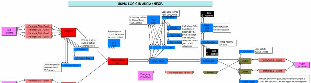
4 PAGE 4 DAP file of the month The.dap file of the month illustrates a couple of logic concepts we mentioned in this technical Newsletter. Although this design is a pure fiction, it summarizes well few of the typical applications: Automixer s logic outputs to control PTZ camera or video switcher Partition sensors automatically control the state of the room combiner Momentary switches control Up and Down volume Event scheduler controls System ON/OFF and 3rd party devices such as blinds, lighting controller Select8 is used to override event scheduler to manually disable automatic system ON and shutdown Logic states and logic delays control Fade IN and Fade OUT of the system Combination of momentary switches and flip flop are used to control muting of Audio When emergency page is made, the ducker is activated and ducks program audio. Manual override of the system (e.g. key operated connected to VCB) is then required to set the system back to its default state. Technical Support Team Announcement A new application note has been published by the Biamp Support Group and is available for download on our website in the Tech Support section ( Understanding Discovery methods in Audia/Nexia/DaVinci software will give you a complete analysis on how UDP broadcast and TCP discovery methods differ. We recommend all designers who are new to the field of Audia/Nexia software to carefully read the application note. For advanced programmers, useful information about VPN connections and troubleshooting techniques may be of interest to you. Biamp Technical Support Team Technical Support Manager Kiley Henner khenner@biamp.com Chris Flanagan cflanagan@biamp.com Michael Erwin merwin@biamp.com Asia/Pacific region Tony Rouget arouget@biamp.com Phone: Skype ID: tonybiamp Biamp Sales Team Contact Info Regional Sales Managers Contact Biamp Systems by phone ( or ) for contact information of the local regional sales manager in charge of your area.
5 PAGE 5
Interfacing Clockaudio microphones with the Logic Box
 Interfacing Clockaudio microphones with the INTRODUCTION One popular application for the is to interface with conferencing microphones that feature mute switches and LED indicators, and Clockaudio is a
Chapter 4: FLIP FLOPS. (Sequential Circuits) By: Siti Sabariah Hj. Salihin ELECTRICAL ENGINEERING DEPARTMENT EE 202 : DIGITAL ELECTRONICS 1
 By: Siti Sabariah Hj. Salihin ELECTRICAL ENGINEERING DEPARTMENT EE 202 : DIGITAL ELECTRONICS 1") Chapter 4: FLIP FLOPS (Sequential Circuits) By: Siti Sabariah Hj. Salihin ELECTRICAL ENGINEERING DEPARTMENT 1 CHAPTER 4 : FLIP FLOPS Programme Learning Outcomes, PLO Upon completion of the programme, graduates
Chapter 4: FLIP FLOPS (Sequential Circuits) By: Siti Sabariah Hj. Salihin ELECTRICAL ENGINEERING DEPARTMENT 1 CHAPTER 4 : FLIP FLOPS Programme Learning Outcomes, PLO Upon completion of the programme, graduates
DIGITAL ELECTRONICS. Methods & diagrams : 1 Graph plotting : - Tables & analysis : - Questions & discussion : 6 Performance : 3
 DIGITAL ELECTRONICS Marking scheme : Methods & diagrams : 1 Graph plotting : - Tables & analysis : - Questions & discussion : 6 Performance : 3 Aim: This experiment will investigate the function of the
Digital Logic Circuits
 Digital Logic Circuits Let s look at the essential features of digital logic circuits, which are at the heart of digital computers. Learning Objectives Understand the concepts of analog and digital signals
Example KodeKLIX Circuits
 Example KodeKLIX Circuits Build these circuits to use with the pre-installed* code * The code is available can be re-downloaded to the SnapCPU at any time. The RGB LED will cycle through 6 colours Pressing
PROFESSIONAL AUDIO SYSTEMS. Product Catalog. effective april 2007 PRODUCT OFFERINGS AUDIA NEXIA AMPLIFIERS MIXER/AMPLIFIERS MIXERS ACCESSORIES
 PROFESSIONAL AUDIO SYSTEMS Product Catalog effective april 2007 PRODUCT OFFERINGS AUDIA NEXIA AMPLIFIERS MIXER/AMPLIFIERS MIXERS ACCESSORIES Dear Audio Professional: Headquarters Biamp Systems 10074 S.W.
Programming Parameter Guide
 Secure Wireless Microphone ELITE PRO Programming Parameter Guide rev:1 How to use Programmer: Start Programming application Runs On PC or Mac running Windows 7/10. To put Handset into programming mode,
Positive and Negative Logic
 Course: B.Sc. Applied Physical Science (Computer Science) Year & Sem.: IInd Year, Sem - IIIrd Subject: Computer Science Paper No.: IX Paper Title: Computer System Architecture Lecture No.: 4 Lecture Title:
Design and build a prototype digital motor controller with the following features:
 Nov 3, 26 Project Digital Motor Controller Tom Kovacsi Andrew Rossbach Arnold Stadlin Start: Nov 7, 26 Project Scope Design and build a prototype digital motor controller with the following features:.
This Figure here illustrates the operation for a 2-input OR gate for all four possible input combinations.
 Course: B.Sc. Applied Physical Science (Computer Science) Year & Sem.: IInd Year, Sem - IIIrd Subject: Computer Science Paper No.: IX Paper Title: Computer System Architecture Lecture No.: 5 Lecture Title:
Java Bread Board Introductory Digital Electronics Exercise 2, Page 1
 Java Bread Board Introductory Digital Electronics Exercise 2, Page 1 JBB Excercise 2 The aim of this lab is to demonstrate how basic logic gates can be used to implement simple memory functions, introduce
Programming Parameters - Feature Comparison : Rev 1
 Secure Wireless Microphone ELITE PRO CLASSIC Programming Parameters - Feature Comparison : Rev 1 How to use Programmer: Start Programming application Runs On PC or Mac running Windows 7/8. To put Handset
B.E. SEMESTER III (ELECTRICAL) SUBJECT CODE: X30902 Subject Name: Analog & Digital Electronics
 SUBJECT CODE: X30902 Subject Name: Analog & Digital Electronics") B.E. SEMESTER III (ELECTRICAL) SUBJECT CODE: X30902 Subject Name: Analog & Digital Electronics Sr. No. Date TITLE To From Marks Sign 1 To verify the application of op-amp as an Inverting Amplifier 2 To
B.E. SEMESTER III (ELECTRICAL) SUBJECT CODE: X30902 Subject Name: Analog & Digital Electronics Sr. No. Date TITLE To From Marks Sign 1 To verify the application of op-amp as an Inverting Amplifier 2 To
Table of Contents Thank You... 5 What is the Liquid Router?... 5 Operating Guidelines... 6
 Table of Contents Thank You... 5 What is the Liquid Router?... 5 Operating Guidelines... 6 Powering the unit... 6 Which MIDI Cables Should Be Used... 6 Care and Cleaning... 7 Installing Expansion Devices...
Serial Control Hardware (RS-485)
") Serial Control Hardware (RS-485) The RS-485 port is available on either of the RJ45 connectors on the back panel of the unit. The 485 network operates at 19.2 kbaud, 8 bits, 1 stop bit/no parity/no hardware
Serial Control Hardware (RS-485) The RS-485 port is available on either of the RJ45 connectors on the back panel of the unit. The 485 network operates at 19.2 kbaud, 8 bits, 1 stop bit/no parity/no hardware
ENGR-4300 Fall 2006 Project 3 Project 3 Build a 555-Timer
 ENGR-43 Fall 26 Project 3 Project 3 Build a 555-Timer For this project, each team, (do this as team of 4,) will simulate and build an astable multivibrator. However, instead of using the 555 timer chip,
Number system: the system used to count discrete units is called number. Decimal system: the number system that contains 10 distinguished
 Number system: the system used to count discrete units is called number system Decimal system: the number system that contains 10 distinguished symbols that is 0-9 or digits is called decimal system. As
2 Logic Gates THE INVERTER. A logic gate is an electronic circuit which makes logic decisions. It has one output and one or more inputs.
 2 Logic Gates A logic gate is an electronic circuit which makes logic decisions. It has one output and one or more inputs. THE INVERTER The inverter (NOT circuit) performs the operation called inversion
Digital Fundamentals. Lab 4 EX-OR Circuits & Combinational Circuit Design
 Richland College School of Engineering & Technology Rev. 0 B. Donham Rev. 1 (7/2003) J. Horne Rev. 2 (1/2008) J. Bradbury Digital Fundamentals CETT 1425 Lab 4 EX-OR Circuits & Combinational Circuit Design
Module -18 Flip flops
 1 Module -18 Flip flops 1. Introduction 2. Comparison of latches and flip flops. 3. Clock the trigger signal 4. Flip flops 4.1. Level triggered flip flops SR, D and JK flip flops 4.2. Edge triggered flip
Lecture 2: Digital Logic Basis
 Lecture 2: Digital Logic Basis Xufeng Kou School of Information Science and Technology ShanghaiTech University 1 Outline Truth Table Basic Logic Operation and Gates Logic Circuits NOR Gates and NAND Gates
Spec. Instructor: Center
 PDHonline Course E379 (5 PDH) Digital Logic Circuits Volume III Spec ial Logic Circuits Instructor: Lee Layton, P.E 2012 PDH Online PDH Center 5272 Meadow Estatess Drive Fairfax, VA 22030-6658 Phone &
ELECTROVATE. Electromania Problem Statement Discussion
 ELECTROVATE Electromania Problem Statement Discussion An Competition Basic Circuiting What is Electromania? Innovation Debugging Lets Revise the Basics Electronics Digital Analog Digital Electronics Similar
Digital Electronics Course Objectives
 Digital Electronics Course Objectives In this course, we learning is reported using Standards Referenced Reporting (SRR). SRR seeks to provide students with grades that are consistent, are accurate, and
Multiple input gates. The AND gate
 Multiple input gates Inverters and buffers exhaust the possibilities for single-input gate circuits. What more can be done with a single logic signal but to buffer it or invert it? To explore more logic
DIGITAL UTILITY SUB- SYSTEMS
 DIGITAL UTILITY SUB- SYSTEMS INTRODUCTION... 138 bandpass filters... 138 digital delay... 139 digital divide-by-1, 2, 4, or 8... 140 digital divide-by-2, 3, 4... 140 digital divide-by-4... 141 digital
This document is intended for Lighting Control Systems professionals
 This document is intended for Lighting Control Systems professionals This document applies to fixture with factory installed SVPD1, SVPD2, SVPD3 integrated sensors. Table of contents Quick Reference Guide...
COMPUTER ORGANIZATION & ARCHITECTURE DIGITAL LOGIC CSCD211- DEPARTMENT OF COMPUTER SCIENCE, UNIVERSITY OF GHANA
 COMPUTER ORGANIZATION & ARCHITECTURE DIGITAL LOGIC LOGIC Logic is a branch of math that tries to look at problems in terms of being either true or false. It will use a set of statements to derive new true
In this lecture: Lecture 3: Basic Logic Gates & Boolean Expressions
 In this lecture: Lecture 3: Basic Logic Gates & Boolean Expressions Dr Pete Sedcole Department of E&E Engineering Imperial College London http://cas.ee.ic.ac.uk/~nps/ (Floyd 3.1 3.6, 4.1) (Tocci 3.1 3.9)
Checking your technology
 Below are instructions to make sure your technology is ready for your Nepris online session. We use Zoom Cloud Meetings as our video tool. The first few pages will step you through the process of making
Philips Ledalite Phone: Fax: Web: Programming Guide Version 2.0
 Philips Ledalite Phone: 604.888.6811 Fax: 800.665.5223 Web: www.ledalite.com Programming Guide Version 2.0 AIRWAVE PROGRAMMING GUIDE 1.0 Linking/Unlinking an Airwave Switch or Photosensor to a Transceiver
1.) If a 3 input NOR gate has eight input possibilities, how many of those possibilities result in a HIGH output? (a.) 1 (b.) 2 (c.) 3 (d.) 7 (e.
 If a 3 input NOR gate has eight input possibilities, how many of those possibilities result in a HIGH output? (a.) 1 (b.) 2 (c.) 3 (d.) 7 (e.") Name: Multiple Choice 1.) If a 3 input NOR gate has eight input possibilities, how many of those possibilities result in a HIGH output? (a.) 1 (b.) 2 (c.) 3 (d.) 7 (e.) 8 2.) The output of an OR gate with
Name: Multiple Choice 1.) If a 3 input NOR gate has eight input possibilities, how many of those possibilities result in a HIGH output? (a.) 1 (b.) 2 (c.) 3 (d.) 7 (e.) 8 2.) The output of an OR gate with
COMBINATIONAL and SEQUENTIAL LOGIC CIRCUITS Hardware implementation and software design
 PH-315 COMINATIONAL and SEUENTIAL LOGIC CIRCUITS Hardware implementation and software design A La Rosa I PURPOSE: To familiarize with combinational and sequential logic circuits Combinational circuits
PRODUCTCATALOG THE DIFFERENCE IS HEAR
 PRODUCTCATALOG THE DIFFERENCE IS HEAR DANTE NETWORKED AMPLIFIERS PRODUCT FORM CHANNELS WATTS IMPEDANCE INPUTS ZONE SIZE FEATURES PAGE FACTOR CHANNEL NUMBER AV8-2 PoE+ LZ Flange Mt 2 8W 4 Ω / 8 Ω 2 Net
Schmitt Trigger Inputs, Decoders
 Schmitt Trigger, Decoders Page 1 Schmitt Trigger Inputs, Decoders TTL Switching In this lab we study the switching of TTL devices. To do that we begin with a source that is unusual for logic circuits,
UNIVERSITY OF CALIFORNIA, DAVIS Department of Electrical and Computer Engineering. EEC 180A DIGITAL SYSTEMS I Winter 2015
 UNIVERSITY OF CALIFORNIA, DAVIS Department of Electrical and Computer Engineering EEC 180A DIGITAL SYSTEMS I Winter 2015 LAB 2: INTRODUCTION TO LAB INSTRUMENTS The purpose of this lab is to introduce the
Kismet Interface Overview
 The following tutorial will cover an in depth overview of the benefits, features, and functionality within Unreal s node based scripting editor, Kismet. This document will cover an interface overview;
1. The decimal number 62 is represented in hexadecimal (base 16) and binary (base 2) respectively as
 and binary (base 2) respectively as") BioE 1310 - Review 5 - Digital 1/16/2017 Instructions: On the Answer Sheet, enter your 2-digit ID number (with a leading 0 if needed) in the boxes of the ID section. Fill in the corresponding numbered
BioE 1310 - Review 5 - Digital 1/16/2017 Instructions: On the Answer Sheet, enter your 2-digit ID number (with a leading 0 if needed) in the boxes of the ID section. Fill in the corresponding numbered
Re: Design Specifications for a Voice Activated Remote Control System (ENSC 340 Project)
") October 31, 2002 Dr. Andrew Rawicz School of Engineering Science Simon Fraser University Burnaby, British Columbia V5A 1S6 Re: Design Specifications for a Voice Activated Remote Control System (ENSC 340
October 31, 2002 Dr. Andrew Rawicz School of Engineering Science Simon Fraser University Burnaby, British Columbia V5A 1S6 Re: Design Specifications for a Voice Activated Remote Control System (ENSC 340
ZT 20xx IOG SERIES. Quick Start 1 What s in the Shipping Package? ANT
 ZT 20xx IOG SERIES Quick Start 1 What s in the Shipping Package? The shipping package contains the following items: ZT 20xx IOG Module ANT 124 05 Quick Start If any of these items are missing or damaged,
Lab 2 Revisited Exercise
 Lab 2 Revisited Exercise +15V 100k 1K 2N2222 Wire up led display Note the ground leads LED orientation 6.091 IAP 2008 Lecture 3 1 Comparator, Oscillator +5 +15 1k 2 V- 7 6 Vin 3 V+ 4 V o Notice that power
CAT-800 Repeater Controller Computer Automation Technology, Inc
 CAT-800 Repeater Controller Computer Automation Technology, Inc 7378 W. Atlantic Blvd. #239 Margate, Florida 33063 Phone: (954) 978-6171 Fax: (561) 465-5891 Internet: http://www.catauto.com Table of Contents
hij Teacher Resource Bank GCE Electronics Exemplar Examination Questions ELEC2 Further Electronics
 hij Teacher Resource Bank GCE Electronics Exemplar Examination Questions ELEC2 Further Electronics The Assessment and Qualifications Alliance (AQA) is a company limited by guarantee registered in England
HIL Simulation Lab Work
 2017.03.09 HIL Simulation Lab Work with Step by Step Exercises that you can do in your own Pace http://home.hit.no/~hansha/?lab=hilsim Hans-Petter Halvorsen Introduction to HIL Lab Work Hans-Petter Halvorsen
ENG 100 Electric Circuits and Systems Lab 6: Introduction to Logic Circuits
 ENG 100 Electric Circuits and Systems Lab 6: Introduction to Logic Circuits Professor P. Hurst Lecture 5:10p 6:00p TR, Kleiber Hall Lab 2:10p 5:00p F, 2161 Kemper Hall LM741 Operational Amplifier Courtesy
Sequential Logic Circuits
 Exercise 2 Sequential Logic Circuits 1 - Introduction Goal of the exercise The goals of this exercise are: - verify the behavior of simple sequential logic circuits; - measure the dynamic parameters of
Additional Programs for the Electronics Module Part No
 Additional Programs for the Electronics Module Part No. 5263 Contents:. Additional programs for the Electronics Module....2 Wiring of the inputs and outputs... 2.3 Additional programs for digital technology...
Kameleono. User Guide Ver 1.2.3
 Kameleono Ver 1.2.3 Table of Contents Overview... 4 MIDI Processing Chart...5 Kameleono Inputs...5 Kameleono Core... 5 Kameleono Output...5 Getting Started...6 Installing... 6 Manual installation on Windows...6
ECEN 449: Microprocessor System Design Department of Electrical and Computer Engineering Texas A&M University
 ECEN 449: Microprocessor System Design Department of Electrical and Computer Engineering Texas A&M University Prof. Sunil P Khatri (Lab exercise created and tested by Ramu Endluri, He Zhou, Andrew Douglass
SOLAROCONSOLE. Software Guide
 SOLAROCONSOLE Software Guide 1 Table of Contents This User Manual will cover the following topics: Software Installation 2 Device Connectivity 3 Getting Started in SolaroConsole 5 Network View 6 Connection
Digital Electronic Concepts
 Western Technical College 10662137 Digital Electronic Concepts Course Outcome Summary Course Information Description Career Cluster Instructional Level Total Credits 4.00 Total Hours 108.00 This course
Syllabus: Digital Electronics (DE) (Project Lead The Way)
 (Project Lead The Way)") Course Overview: Digital electronics and micro computers. This is a course in applied logic that encompasses the application of electronic circuits and devices. Computer simulation software is used to
Course Overview: Digital electronics and micro computers. This is a course in applied logic that encompasses the application of electronic circuits and devices. Computer simulation software is used to
HIGH LOW Astable multivibrators HIGH LOW 1:1
 1. Multivibrators A multivibrator circuit oscillates between a HIGH state and a LOW state producing a continuous output. Astable multivibrators generally have an even 50% duty cycle, that is that 50% of
BINARY. User Manual. Version 1.0
 !! BINARY User Manual Version 1.0 BINARY Binary is a 1-bit analog computer that takes up to six inputs and determines whether the output voltage should be high (+) or low (). Binary was designed to take
AMX touchscreen in rooms with two projectors User Guide
 \ AMX touchscreen in rooms with two projectors User Guide Overview The AMX touchscreen allows you to control the AV equipment in CATS lecture and tutorial rooms. This guide will show how you how to use
CAT-260 Repeater Controller Computer Automation Technology, Inc
 CAT-260 Repeater Controller Computer Automation Technology, Inc 7378 W. Atlantic Blvd. #239 Margate, Florida 33063 Phone: (954) 978-6171 Fax: (561) 465-5891 Internet: http://www.catauto.com Table of Contents
Course Outline Cover Page
 College of Micronesia FSM P.O. Box 159 Kolonia, Pohnpei Course Outline Cover Page Digital Electronics I VEE 135 Course Title Department and Number Course Description: This course provides the students
XIM Gen4 Sensor Programming Examples. Rev /05/2016
 XIM Gen Sensor Programming Examples Rev 0.6 2/0/206 Overview The latest XIM Gen firmware (V0.28), Xsensor firmware (V0.0) and XIM-BLE Control Panel (V..) update includes significant changes to sensor support.
CAT-700 Repeater Controller
 CAT-700 Repeater Controller Computer Automation Technology, Inc. 4631 N.W. 31st Avenue, Suite 142 Fort Lauderdale, Florida 33309 Phone: (954) 978-6171 Fax: (561) 488-2894 Internet: http://www.catauto.com
For the op amp circuit above, how is the output voltage related to the input voltage? = 20 k R 2
 Golden Rules for Ideal Op Amps with negative feedback: 1. The output will adjust in any way possible to make the inverting input and the noninverting input terminals equal in voltage. 2. The inputs draw
Relay Driver Overview and Applications
 Relay Driver Overview and Applications Describes Basic and Advanced Settings for common and alternative/novel uses for the Relay driver (RD-1). Morningstar s Relay Driver (RD-1) is a fully programmable
AD U DAB/FM Tuner. Item ref: UK User Manual
 AD-100 1U DAB/FM Tuner Item ref: 952.979UK User Manual Caution: Please read this manual carefully before operating Damage caused by misuse is not covered by the warranty Introduction Thank you for choosing
CMOS Digital Integrated Circuits Analysis and Design
 CMOS Digital Integrated Circuits Analysis and Design Chapter 8 Sequential MOS Logic Circuits 1 Introduction Combinational logic circuit Lack the capability of storing any previous events Non-regenerative
Associate In Applied Science In Electronics Engineering Technology Expiration Date:
 PROGRESS RECORD Study your lessons in the order listed below. Associate In Applied Science In Electronics Engineering Technology Expiration Date: 1 2330A Current and Voltage 2 2330B Controlling Current
The Non Inverting Buffer
 The Non Inverting Buffer We now spend some time investigating useful circuit elements that do not directly implement Boolean functions. The first element is the non inverting buffer. This is logically
Modbus communication module for TCX2: AEX-MOD
 Modbus communication module for TCX2: Communication Specification TCX2 is factory installed in TCX2 series controllers with -MOD suffix, and is also available separately upon request for customer installation
Getting Started with TrangoLink
 Getting Started with TrangoLink Overview: TrangoLink allows you to configure and monitor your EAGLE PLUS, FALCON, or PTZ-900 transmitters and receivers. On the EAGLE PLUS and FALCON transmitters, you can
Tsunami Digital Sound Decoder. Quick Start Guide for the Blackstone Models C-19
 Tsunami Digital Sound Decoder Quick Start Guide for the Blackstone Models C-19 May 2011 Notice The information in this document is subject to change without notice. Neither Blackstone Models or SoundTraxx
Chapter 3 Describing Logic Circuits Dr. Xu
 Chapter 3 Describing Logic Circuits Dr. Xu Chapter 3 Objectives Selected areas covered in this chapter: Operation of truth tables for AND, NAND, OR, and NOR gates, and the NOT (INVERTER) circuit. Boolean
Course Introduction. Content 20 pages 3 questions. Learning Time 30 minutes
 Purpose The intent of this course is to provide you with information about the main features of the S08 Timer/PWM (TPM) interface module and how to configure and use it in common applications. Objectives
Manual written by Alessio Santini, Simone Fabbri, and Brian Smith. Manual Version 1.0 (01/2015) Product Version 1.0 (01/2015)
 Product Version 1.0 (01/2015)") Cedits bim bum bam Manual written by Alessio Santini, Simone Fabbri, and Brian Smith. Manual Version 1.0 (01/2015) Product Version 1.0 (01/2015) www.k-devices.com - support@k-devices.com K-Devices, 2015.
Cedits bim bum bam Manual written by Alessio Santini, Simone Fabbri, and Brian Smith. Manual Version 1.0 (01/2015) Product Version 1.0 (01/2015) www.k-devices.com - support@k-devices.com K-Devices, 2015.
OCCUPANCY SENSOR REMOTE USER GUIDE
 OCCUPANCY SENSOR REMOTE USER GUIDE Use the handheld programming remote to test and adjust the settings of your occupancy sensor, which can accommodate up to six sensor parameter profiles. FSP-2X1 is the
TempoTreadle. Why TempoTreadle? Treadle Tracking System for Traditional Looms
 Why TempoTreadle? TempoTreadle is a device you add to your loom to make your weaving process more accurate and stress free. With an audible error beep upon any treadling mistake, you can quickly correct
Chapter 3 Digital Logic Structures
 Chapter 3 Digital Logic Structures Transistor: Building Block of Computers Microprocessors contain millions of transistors Intel Pentium 4 (2): 48 million IBM PowerPC 75FX (22): 38 million IBM/Apple PowerPC
CAT-700B Repeater Controller Computer Automation Technology, Inc
 CAT-00B Repeater Controller Computer Automation Technology, Inc N.W. st Avenue, Suite Fort Lauderdale, Florida 0 Phone: () 8- Fax: () 88-8 Internet: http://www.catauto.com Table of Contents Chapter Page.
CS/ECE 252: INTRODUCTION TO COMPUTER ENGINEERING UNIVERSITY OF WISCONSIN MADISON
 CS/ECE 252: INTRODUCTION TO COMPUTER ENGINEERING UNIVERSITY OF WISCONSIN MADISON Instructor: Andy Phelps TAs: Newsha Ardalani, Peter Ohmann, and Jai Menon Midterm Examination 2 In Class (50 minutes) Wednesday,
SPECIMEN. Candidate Number
 Advanced Subsidiary GCE Electronics Unit F612: Signal Processors Specimen Paper Candidates answer on the question paper. Additional Materials: Scientific calculator Candidate Name Centre Number INSTRUCTIONS
DIGITAL ELECTRONICS: LOGIC AND CLOCKS
 DIGITL ELECTRONICS: LOGIC ND CLOCKS L 9 INTRO: INTRODUCTION TO DISCRETE DIGITL LOGIC, MEMORY, ND CLOCKS GOLS In this experiment, we will learn about the most basic elements of digital electronics, from
ECE 5670/6670 Project. Brushless DC Motor Control with 6-Step Commutation. Objectives
 ECE 5670/6670 Project Brushless DC Motor Control with 6-Step Commutation Objectives The objective of the project is to build a circuit for 6-step commutation of a brushless DC motor and to implement control
C Series Functional Safety
 SAFETY MANUAL C Series Functional Safety This document provides information about developing, deploying, and running Functional Safety systems using C Series Functional Safety modules. C Series Functional
Q181EB Expression Block Controller
 The controller produces a voltage as you press the block, similar to the Ondes Martenot and other instruments. Perfect for controlling amplitude as you play notes on the keyboard, to control filter frequency,
ENGR 210 Lab 12: Analog to Digital Conversion
 ENGR 210 Lab 12: Analog to Digital Conversion In this lab you will investigate the operation and quantization effects of an A/D and D/A converter. A. BACKGROUND 1. LED Displays We have been using LEDs
KIRNU - CREAM MOBILE Kirnu Interactive
 KIRNU - CREAM MOBILE Kirnu Interactive www.kirnuarp.com 1 Top elements Song selection MIDI in/out channel Status Messages Loading/Saving track presets Panic button MIDI learn Global section Track section
Shown here is a schematic diagram for a real inverter circuit, complete with all necessary components for efficient and reliable operation:
 The NOT gate The single-transistor inverter circuit illustrated earlier is actually too crude to be of practical use as a gate. Real inverter circuits contain more than one transistor to maximize voltage
How to Guide: Controlling Blinds in C-Bus
 How to Guide: Controlling Blinds in C-Bus This document is a guide to controlling electrical blinds with C-Bus. Part 1 shows how the blind could be controlled by C-Bus directly and part 2 shows how C-Bus
Digital Electronics. A. I can list five basic safety rules for electronics. B. I can properly display large and small numbers in proper notation,
 St. Michael Albertville High School Teacher: Scott Danielson September 2016 Content Skills Learning Targets Standards Assessment Resources & Technology CEQ: WHAT MAKES DIGITAL ELECTRONICS SO IMPORTANT
TRWinProg 101by Chris Bowman October 10
 TRWinProg 101by Chris Bowman October 10 TRWinProg is a Windows based program for serial programming of encoders. The program allows viewing of setup data stored within the encoder and allowing the user
Debugging a Boundary-Scan I 2 C Script Test with the BusPro - I and I2C Exerciser Software: A Case Study
 Debugging a Boundary-Scan I 2 C Script Test with the BusPro - I and I2C Exerciser Software: A Case Study Overview When developing and debugging I 2 C based hardware and software, it is extremely helpful
Logic diagram: a graphical representation of a circuit
 LOGIC AND GATES Introduction to Logic (1) Logic diagram: a graphical representation of a circuit Each type of gate is represented by a specific graphical symbol Truth table: defines the function of a gate
Course Overview. Course Overview
 Course Overview Where does this course fit into the Electrical Engineering curriculum? Page 5 Course Overview Where does this course fit into the Computer Engineering curriculum? Page 6 3 Course Content
As you can see, by varying the turn-on point, the amount of power getting to the bulb is adjustable, and hence the light output can be controlled.
 Digital Light Dimming Circuit Some light dimmer history Light dimming is based on adjusting the voltage which gets to the lamp. Light dimming has been possible for many decades by using adjustable power
PHYSICS 536 Experiment 14: Basic Logic Circuits
 PHYSICS 5 Experiment 4: Basic Logic Circuits Several T 2 L ICs will be used to illustrate basic logic functions. Their pin connections are shown in the following sketch, which is a top view. 4 2 9 8 +5V
CHAPTER 6 DIGITAL INSTRUMENTS
 CHAPTER 6 DIGITAL INSTRUMENTS 1 LECTURE CONTENTS 6.1 Logic Gates 6.2 Digital Instruments 6.3 Analog to Digital Converter 6.4 Electronic Counter 6.6 Digital Multimeters 2 6.1 Logic Gates 3 AND Gate The
M Series RF Power Supply (Generator) Analog Interface Connections
 Analog Interface Connections") M Series RF Power Supply (Generator) Analog Interface Connections The analog interface connector is located on the rear panel of the Radio Frequency Power Supply. Control and status signals for the RF
M Series RF Power Supply (Generator) Analog Interface Connections The analog interface connector is located on the rear panel of the Radio Frequency Power Supply. Control and status signals for the RF
Chapter 7: Instrumentation systems
 Chapter 7: Instrumentation systems Learning Objectives: At the end of this topic you will be able to: describe the use of the following analogue sensors: thermistors strain gauge describe the use of the
Radio Systems Millenium-A Analog Console
 Radio Systems Millenium-A Console Page 1 Radio Systems Millenium-A Analog Console Installation and Operation Manual Radio Systems Millenium Analog Broadcast Manual Part # MAN-MILLCONA For Console Models:
Name EGR 2131 Lab #2 Logic Gates and Boolean Algebra Objectives Equipment and Components Part 1: Reading Pin Diagrams 7400 (TOP VIEW)
") Name EGR 23 Lab #2 Logic Gates and Boolean Algebra Objectives ) Become familiar with common logic-gate chips and their pin numbers. 2) Using breadboarded chips, investigate the behavior of NOT (Inverter),
Name EGR 23 Lab #2 Logic Gates and Boolean Algebra Objectives ) Become familiar with common logic-gate chips and their pin numbers. 2) Using breadboarded chips, investigate the behavior of NOT (Inverter),
MediaMatrix X-Frame 88
 S P E C I F I C A T I O N S MediaMatrix X-Frame 88 Description The X-Frame 88 is a fully programmable, fully configurable, Digital Signal Processor (DSP) based audio processing and control system. It includes
MAINTENANCE MANUAL DIGITAL SELECTOR MODULE 19D902519G1 TABLE OF CONTENTS
 D MAINTENANCE MANUAL DIGITAL SELECTOR MODULE 19D902519G1 TABLE OF CONTENTS Page SPECIFICATIONS...2 CIRCUIT AND FUNCTIONAL DESCRIPTION...3 CONNECTORS AND SYSTEM INTERFACE...4 DIGITAL SELECTOR MODULE AND
Number of Lessons:155 #14B (P) Electronics Technology with Digital and Microprocessor Laboratory Completion Time: 42 months
 Electronics Technology with Digital and Microprocessor Laboratory Completion Time: 42 months") PROGRESS RECORD Study your lessons in the order listed below. Number of Lessons:155 #14B (P) Electronics Technology with Digital and Microprocessor Laboratory Completion Time: 42 months 1 2330A Current
PROGRESS RECORD Study your lessons in the order listed below. Number of Lessons:155 #14B (P) Electronics Technology with Digital and Microprocessor Laboratory Completion Time: 42 months 1 2330A Current