SPPA-E3000 Electrical Solutions Excitation and Startup Frequency Converter Systems
|
|
|
- Maria Mills
- 5 years ago
- Views:
Transcription

1 SPPA-E3000 Electrical Solutions Excitation and Startup Frequency Converter Systems Plant Survey & Characteristics 2018 Instrumentation, Controls & Digitalization PERSONAL SAFETY PRECAUTIONS: NOTE: we follow a zero harm philosophy, safety precautions must be considered! Wear personal safety equipment! The system to be accessed and assessed has to be isolated and taken out of service! Before opening any cubicle doors, make sure the system is isolated! In case of dangerous materials used, like Asbestos, make sure use caution to protect personal safety! Make sure cubicle doors are able to open for survey! Table of Contents: GENERAL TECHNICAL INFORMATION 3 ( select retrofit case ) TYPICAL RETROFIT OVERVIEW 4 GENERATOR- / SUPPLY- DATA 5 RETROFIT CASE 1 EXCITATION regulator unit only 7 RETROFIT CASE 2 EXCITATION including power section 9 RETROFIT CASE 3 Startup Frequency Converter / SFC retrofit 11 MEASURMENTS ONSITE Conditions 13 PHOTOGRAPH Philosoph 15 PHOTOGRAPHS from ONSITE 17 REQUEST AN OFFER To request an offer for modernizing your Excitation system please complete and return the plant survey sheet to Nicolai Wißler nicolai.wissler@siemens.com
2 General technical information of application Application Data (existing) General Application: Hydro Pumped Storage Steam Gas Synchronous Condenser Existing System: THYRIPOL SFC / SEE compact SFC stand alone RG3 THYRIPART SEMIPOL Others Manufacturer others: Retrofit case Retrofit objects: Control- / regulator unit only Full / complete retrofit (incl. power section) SFC equipment only Excitation equipment only ( SES ) SFC / SES compact design ( retrofit case 2 and 3 ) DCS modification planned / DCS Type planned: Generator protection modification planned / Protection Type planned: Cubicle location close to sea side (sea water - air conditions) Air conditioned equipment room Seismic Rating Required Cubicle location ambient temperature: C Cubicle location humidity rating: % Cubicle location altitude: m (measured from sea level = 0 m) Cubicle location distance to generator / motor: : m 2
3 Typical Retrofit Overview Startup Frequency Converter ( SFC ) SFC transformer Un = In = f = PF = Sn = Generator 3 ~ Uf = If = Uf = If = SFC Static Excitation System ( SES ) SES SES CB SES transformer Brushless Excitation System ( RG3 ) SFC CB Supply from bus duct Supply from AUX 3~ Main Exciter Pilot ( PMG ) 3~ DC Main Exciter Ue = Ie = RG3 PMG 3~ 1~ AUX Supply == 3~ 1~ NOTE: Compact units will combine SES and SFC into one compact unit (retrofit case 2 and 3) 3
4 Generator- / Motor- Data of existing system OEM: Year of manufacturing: Machine number: Rated Power SN: MVA cos φn: Frequency f: Hz Speed: rpm Nominal Voltage UGN: kv Nominal Current IGN: ka Nominal Field Voltage UfN: V Nominal Field Current IfN: A Ceiling Field Voltage UfP: V Ceiling Field Current IfP: A No Load Field Voltage Uf0: V No Load Field Current If0: A Stator winding connection: (example: YYY) ( NOTE: All photographs taken of generator name plate to be with no flash light reflection, min. 12 Meg. pixel ) Excitation- / Exciter Machine- / PMG- Data of existing system (if applicable) EXCITATION SYSTEM (if applicable): No-load Excitation Voltage: V No-load Excitation Current: A Nominal Excitation Voltage: V Nominal Excitation Current: A Max. Continuous Excitation Current: A Ceiling Voltage: V Ceiling Current, time limit: A (Uf0 resp. UE0) (If0 resp. IE0) (UfN resp. UEN) (IfN resp. IEN) (Ifmax resp. IEmax) (UfP resp. UEP) (IfP resp. IEP) for sec EXCITER MACHINE / EM (if applicable / RG3 only): DC - Exciter Machine 3-phase - Exciter Machine Nominal EM Field Voltage: V Nominal EM Field Current: A Nominal EM Output Voltage: V Nominal EM Output Current: A Nominal EM App. Power: kva Ceiling Voltage: V (UEN) (IEN) (UEMN) (IEMN) (SEN) (UEP) Ceiling Current, time limit: A (IEP) for sec 4
5 PILOT EXCITER / PMG (if applicable / RG3 only): Permanent Magnetic Generator 3-phase 1-phase Nominal PMG Output Voltage: V Nominal PMG Output Current: A Nominal PMG App. Power: kva (UNPMG) (INPMG) (SNPMG) PMG Power Factor: Nominal PMG Frequency: Hz (fnpmg) Nominal PMG speed: rpm PILOT EXCITER / PMG (if applicable / RG3 only): AC Voltage 1 DC Voltage 1 Nominal Voltage: V Nominal Frequency: Hz Nominal Power: kva / kw AC Voltage 1 DC Voltage 1 Nominal Voltage: V Nominal Frequency: Hz Nominal Power: kva / kw Excitation- / SFC- Transformer (if applicable) ( technical data, see sections Retrofit cases 1, 2 or 3 ) 5
6 Technical information, pending on retrofit case Retrofit case 1 -- EXCITATION Control- / regulator unit only Documents from existing system to be collected from client, if possible: 1.) Photo of name plates (original Excitation system) 2.) Photo of name plates (Excitation transformers) 3.) Photo of name plates (Generator, Exciter Machine, PMG) 4.) Single Line Diagram of unit setup 5.) Capability curve of generator / motor 6.) No load characteristics of generator / motor (open circuit + short circuit) 7.) Thermal capability characteristics of generator / motor (thermal curves) 8.) Electrical data sheet of generator / motor (Xd / Xq / inertia, etc.) 9.) Excitation performance characteristics (set point steps, regulator and channel transfers, limiter tests, PSS tests) 10.) VT- & CT- configuration (locations, how many of each, etc.) 11.) Excitation Interface documentation / configuration interfacing to power plant 12.) Excitation circuit diagrams and dimensional drawings of existing system (NOTE: All photographs taken, to be free of flash light reflection with high resolution, min. 12 Meg. pixel) System cubicle color planned ( RAL No.; example RAL 7035 ) Redundant Controls Excitation Fault Recorder Power Factor Controller Reactive Power Controller Hardwired interface to power plant BUS interface to power plant IEC interface MODBUS interface PROFIBUS interface PROFINET interface TCP/IP interface Other interface to power plant Type: PSS 2B PSS 3B AVR AUTO mode with PID Analog outputs of excitation system Total No: AVR REMOTE Control from power plant AVR LOCAL Control via Touch Panel / HMI TIME synch. via NTP TIME synch. via DCF77 Electrical braking Redundant cooling fan Redundant air condition unit No. of RCT (static only) Excitation with AC CB Excitation with DC CB supply from bus duct (static only) AUX supply (static only) SES back to back application (pump storage only) Cubicle Cable Entry: Top Bottom Others: 6
7 Excitation Transformer is existing will remain will be exchangednominal PMG Output Voltage: Transformer Type: Vector Group: Cooling System: Impedance voltage (Uk): % Ratio: kv / V Rated Power: kva AUX supply voltage-levels AC Volt. 400 V 380 V 230 V 110 V others: AC Freq. 400 Hz 60 Hz 50 Hz DC Volt. 220 V 125 V 110 V 24 V RCT spare conditions onsite: No. of spare RCT parts (onsite) No. of spare RCT cooling fans (onsite) Years of RCT operation (existing) Type of RCT spare parts onsite: Others: 7
8 Retrofit case 2 -- EXCITATION including power section / ( compact design if applicable ) Documents from existing system to be collected from client, if possible: 1.) Photo of name plates (original Excitation system) 2.) Photo of name plates (Excitation transformers) 3.) Photo of name plates (Generator, Exciter Machine, PMG) 4.) Single Line Diagram of unit setup 5.) Capability curve of generator / motor 6.) No load characteristics of generator / motor (open circuit + short circuit) 7.) Thermal capability characteristics of generator / motor (thermal curves) 8.) Electrical data sheet of generator / motor (Xd / Xq / inertia, etc.) 9.) Excitation performance characteristics (set point steps, regulator and channel transfers, limiter tests, PSS tests) 10.) VT- & CT- configuration (locations, how many of each, etc.) 11.) Excitation Interface documentation / configuration interfacing to power plant 12.) Excitation circuit diagrams and dimensional drawings of existing system (NOTE: All photographs taken, to be free of flash light reflection with high resolution, min. 12 Meg. pixel) System cubicle color planned ( RAL No.; example RAL 7035 ) Redundant Controls Excitation Fault Recorder Power Factor Controller Reactive Power Controller Hardwired interface to power plant BUS interface to power plant IEC interface MODBUS interface PROFIBUS interface PROFINET interface TCP/IP interface Other interface to power plant Type: PSS 2B PSS 3B AVR AUTO mode with PID Analog outputs of excitation system Total No: AVR REMOTE Control from power plant AVR LOCAL Control via Touch Panel / HMI TIME synch. via NTP TIME synch. via DCF77 Electrical braking Redundant cooling fan Redundant air condition unit No. of RCT (static only) No. of total cubicles Excitation with AC CB Excitation with DC CB supply from bus duct (static only) AUX supply (static only) SES back to back application (pump storage only) Cubicle Cable Entry: Top Bottom Others: 8
9 Excitation Transformer is existing will remain will be exchanged Nominal PMG Output Voltage: Transformer Type: Vector Group: Cooling System: Impedance voltage (Uk): % Ratio: kv / V Rated Power: kva AUX supply voltage-levels AC Volt. 400 V 380 V 230 V 110 V others: AC Freq. 400 Hz 60 Hz 50 Hz DC Volt. 220 V 125 V 110 V 24 V Others: 9
10 Retrofit case 3 -- STARTUP FREQUENCY CONVERTER / SFC / ( compact design if applicable ) Documents from existing system to be collected from client, if possible: 1.) Photo of name plates (original SFC- system) 2.) Photo of name plates (SFC transformer) 3.) Photo of name plates (Generator) 4.) Single Line Diagram of unit setup 5.) Capability curve of generator / motor 6.) No load characteristics of generator / motor (open circuit + short circuit) 7.) Thermal capability characteristics of generator / motor (thermal curves) 8.) Electrical data sheet of generator / motor (Xd / Xq / inertia, etc.) 9.) SFC start up characteristics (start up curves, etc.) 10.) VT- & CT- configuration (locations, how many of each, etc.) 11.) SFC Interface documentation / configuration interfacing to power plant (NOTE: All photographs taken, to be free of flash light reflection with high resolution, min. 12 Meg. pixel) Type of turbine: OEM: SFC DC-link-Power: MW SFC Operating Modes: Washing Purging Turning Black Star Electrical braking One SFC for 1 turbine One SFC for 2 turbines One SFC for 3 turbine One SFC for 4 turbines System cubicle color planned ( RAL No.; example RAL 7035 ) Fault Recorder Startup Excitation existing Startup Excitation required Hardwired interface to power plant BUS interface to power plant IEC interface MODBUS interface PROFIBUS interface PROFINET interface TCP/IP interface Other interface to power plant Analog outputs of SFC system SFC REMOTE Control from power plant SFC LOCAL Control via Touch Panel / HMI TIME synch. via NTP TIME synch. via DCF77 Redundant cooling fan Redundant air condition unit Hardwired interface to SES PROFIBUS interface to SES No. of power stack No. of total cubicles Type: Total No: 10
11 SFC crossover application (for more then 1 unit only) Cubicle Cable Entry: Top Bottom Others: SFC Transformer is existing will remain will be exchanged Transformer Type: Cooling System: Impedance voltage (Uk): % Vector Group: Ratio: kv / V Rated Power: kva Trip- / Switching time of existing CB in front of SFC: ms AUX supply voltage-levels AC Volt. 400 V 380 V 230 V 110 V others: AC Freq. 400 Hz 60 Hz 50 Hz DC Volt. 220 V 125 V 110 V 24 V Others: 11
12 MEASUREMENTS / ON SITE CONDITIONS Equipment room dimensions (LxWxH): Length m x With m x Height m ( take photographs and measurement of critical areas, all the way through from truck off -loading point to power plant / equipment room installation point, to be free of flash light reflection with high resolution, min. 12 Meg. Pixel, sketch of floor and room layout ) Existing equipment dimensions of Excit.-, SFC- and transformer cubicles ( foot print, sketch of layout ) EXAMPLE: Existing equipment cable routing of Excit.-, SFC- and transformer- cubicles ( foot print, sketch of cable routing ) EXAMPLE: 12
13 Cubicle transport way (descriptions example): The cubicle off-loading point from truck is approx. 100 m away from the equipment installation point, inside the equipment room. The way through has got 3 critical areas with the following dimensions Point 1: Length m x With m x Height m Point 2: Length m x With m x Height m Point 3: Length m x With m x Height m etc. Cable routing (descriptions example): Cubicle CONTROLS - interface cable to plant DCS system, cable no.: xxxxx, cubicle entry: BOTTOM-LEFT, spare cable loop: approx.. 2 m - interface cable to plant protection system, cable no.: xxxxx, cubicle entry: BOTTOM-FRONT, spare cable loop: approx.. 3 m - interface cable to plant xxx, cable no.: xxxxx, cubicle entry: BOTTOM-BACK, spare cable loop: approx.. 4 m - power cable to plant xxx, cable no.: xxxxx, cubicle entry: TOP-RIGHT, spare cable loop: approx.. 2 m - Cable entrance BOTTOM of cubicle is closed with fire seal Cubicle RCT 1 - interface cable to CONTROL cubicle, cable no.: xxxxx, cubicle entry: BOTTOM-LEFT, spare cable loop: approx.. 2 m - Cable entrance BOTTOM of cubicle is closed with fire seal Cubicle RCT 2 - interface cable to CONTROL cubicle, cable no.: xxxxx, cubicle entry: BOTTOM-LEFT, spare cable loop: approx.. 2 m - Cable entrance BOTTOM of cubicle is closed with fire seal Cubicle DC CB - power cable to plant xxx, cable no.: xxxxx, cubicle entry: BOTTOM-FRONT, spare cable loop: approx.. 2 m - power cable to plant xxx, cable no.: xxxxx, cubicle entry: BOTTOM-FRONT, spare cable loop: approx.. 1 m - power cable to plant xxx, cable no.: xxxxx, cubicle entry: BOTTOM-FRONT, spare cable loop: approx.. 3 m - Cable entrance BOTTOM of cubicle is not closed with fire seal etc. etc. 13
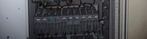
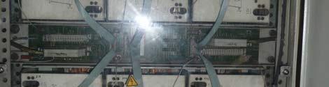
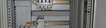
14 ON SITE PHOTOGRAPHS On site photograph example to be taken from each and every cubicle involved in retrofit activities, also transformers EXAMPLE cub. 1: C1_1_F C1_1_R EXAMPLE cub. 2: C2_1_F C2_1_R C1_2_F C1_2_R C2_2_F C2_2_R C1_3_F C1_3_R C2_3_F C2_3_R under floor cable tray C1_4_F C1_4_R cable glanding C1_5_F C1_5_R cable (photography of spare loops) C2_4_F C2_4_R C2_5_F C2_5_R each and every section / cubicle of the SFC / SES will have at least 5 topological photographs from the top to the bottom Photographs shall be taken free of flash light reflection with high resolution, min. 12 Meg. Pixel photograph shall be readable and good to see, even minor details by zooming into the photograph if the cubicle has got a back and a front door installation inside, conclusively 10 pics / cubicle must be taken make notes also about the cable routing inside the cable tunnels / on top of the cable trays, see descriptions of cable routing examples above take photographs of all side equipment, near the SFC / SES cubicles as well take photographs or screenshots of ECS control screens on the DCS side / control room as well take photographs of cubicle cable entries from inside cubicles (cable glanding, fire sealing, etc.) take photographs of control cubicle front door if there are control items (lamps, button, etc.) installed 14
15 NAME CODING of photography s taken: General view (all cubicles, line up, doors closed) Cable floor / cable tray view (all cable entries to cubicles) GEN_1_F (Front Cable_1_F Cable_1_R GEN_2_F (Front) Cable_2_F Cable_2_R GEN_n_F (Front) Cable_3_F Cable_3_R GEN_1_R (Rear) ( Note: make comment to each and every photograph ) GEN_2_R (Rear) GEN_n_R (Rear) Cubicle 1 (from Top to Bottom / Front and Rear) C1_1_F (Front) C1_2_F (Front) C1_3_F (Front) C1_4_F (Front) C1_5_F (Front) Cubicle 2 (from Top to Bottom / Front and Rear) C2_1_F (Front) C2_2_F (Front) C2_3_F (Front) C2_4_F (Front) C2_5_F (Front) Cubicle n (from Top to Bottom / Front and Rear) Cn_1_F (Front) Cn_2_F (Front) Cn_3_F (Front) Cn_4_F (Front) Cn_5_F (Front) C1_1_R (Rear) C1_2_R (Rear) C1_3_R (Rear) C1_4_R (Rear) C1_5_R (Rear) C2_1_R (Rear) C2_2_R (Rear) C2_3_R (Rear) C2_4_R (Rear) C2_5_R (Rear) Cn_1_R (Rear) Cn_2_R (Rear) Cn_3_R (Rear) Cn_4_R (Rear) Cn_5_R (Rear) Comments 15


16 PHOTOGRAPHS: EXAMPLE -- General view GEN_1_F Comment: Example, example, example GEN_1_R Comment: Example, example, example GEN_2_F Comment: Example, example, example GEN_2_R Comment: Example, example, example 16


17 GEN_n_F Comment: Example, example, example GEN_n_R Comment: Example, example, example EXAMPLE -- Cable Floor Cable_1_F Comment: cubicle no., type of cables, cable no., spare loops in meter on cable tray Cable_2_F Comment: cubicle no., type of cables, cable no., spare loops in meter on cable tray 17


18 EXAMPLE -- Transport / Clearance T_1 Comment: crane available, truck access T_2 Comment: crane available, truck access EXAMPLE -- Cubicle 1 18


19 C1_1_F C1_1_R C1_2_F C1_2_R 19


20 C1_3_F C1_3_R C1_4_F C1_4_R 20
21 C1_5_F C1_5_R 21


22 Cubicle 2 C2_1_F C2_1_R C2_2_F C2_2_R 22


23 C2_3_F C2_3_R C2_4_F 23
24 C2_5_F C2_5_R Etc. Etc. Etc. 24
25 Contact Information To request an offer to modernize your Excitation system please complete and return this plant survey sheet to Nicolai Wißler Power Plant / Survey Conducted SITE / PLANT: Address: City: Country: Phone: Contact person: mailto: Unit No.: SURVEY CONDUCTED: Name: Department: Phone: mailto: Participants: Participants: Participants: Participants: Participants: 25
26 Published by and copyright 2018: Siemens AG Gas and Power Division Freyeslebenstrasse Erlangen, Germany For more information contact All rights reserved. Trademarks mentioned in this document arethe property of Siemens AG, its affiliates, ortheir respective owners. Subject to change without prior notice. The information in this document containsgeneral descriptions of the technical options available, which may not apply in all cases. The required technical options should therefore be specified in the contract.
SPPA-E3000 Brushless Excitation System (BES, Type RG3)
") / Technical Description / Juni 2014 SPPA-E3000 Brushless Excitation System (BES, Type RG3) Maximum-availability excitation system for synchronous generators with brushless exciters Answers for energy.
/ Technical Description / Juni 2014 SPPA-E3000 Brushless Excitation System (BES, Type RG3) Maximum-availability excitation system for synchronous generators with brushless exciters Answers for energy.
Static Frequency Converter TMP-TS250. Series
 Static Frequency Converter TMP-TS250 Series Preface SFC is a load commutated inverter LCI, which drives a gas turbine generator like a synchronous motor, and accelerates up to the gas turbine s self-sustaining
Static Frequency Converter TMP-TS370. Series
 Static Frequency Converter TMP-TS370 Series Preface SFC is a load commutated inverter (LCI), which drives a gas turbine generator like a synchronous motor, and accelerates up to the gas turbine s self-sustaining
Excitation Systems. Service Generators SIPOL. Transistorized Excitation Systems for Synchronous Generators. Power Generation
 Excitation Systems Service Generators Transistorized Excitation Systems for Synchronous Generators Power Generation Operating Characteristics High availability Reliability Digital control facilities Very
Excitation Systems RG3 - T4. Transistorized Excitation Systems for Synchronous Generators. Power Generation
 Excitation Systems RG3 - T4 Transistorized Excitation Systems for Synchronous Generators Power Generation Operating Characteristics Reliability High availability Digital control facilities Very good control
Excitation Systems THYRIPART. Compound-Excitation System for Synchronous Generators. Power Generation
 Excitation Systems Compound-Excitation System for Synchronous Generators Power Generation Operating Characteristics Load dependent Short circuit supporting Low voltage gradient dv/dt Black start capability
Instrumentation, Controls & Electrical / Technical Description / February 2016
 / Technical Description / February 2016 SPPA-E3000 Static Excitation Systems (SES) Static excitation systems for excitation and voltage regulation of synchronous machines Answers for energy. Table of contents
ENGINEERING DATA SUBMITTAL For the Interconnection of Generation System
 WHO SHOULD FILE THIS SUBMITTAL: Anyone in the final stages of interconnecting a Generation System with Nodak Electric Cooperative, Inc. This submittal shall be completed and provided to Nodak Electric
Gutor PxW AC UPS Designed for North American Market
 Gutor PxW AC UPS Designed for North American Market PEW 5 200 kva single phase PDW 10 220 kva three phase Higher ratings upon request schneider-electric.com 2 schneider-electric.com schneider-electric.com
OBICON. Perfect Harmony. Short overview. ROBICON Perfect Harmony. System Overview. The Topology. The System. ProToPS. Motors.
 and Drives Control R Interface OBICON Perfect Harmony Short overview 14.03.2007 1 System overview Product features Truly Scaleable Technology 300 kw to 30 MW (Single Channel) Large Number of Framesizes
Orbital GFI Inverter Series
 Orbital GFI Inverter Series Datasheet Key Features One, split or three phases and up to 25 kva Superior efficiency of 95% CAN Bus control and DAQ Power quality and EMC compliance in accordance with European
Impact Assessment Generator Form
 Impact Assessment Generator Form This connection impact assessment form provides information for the Connection Assessment and Connection Cost Estimate. Date: (dd/mm/yyyy) Consultant/Developer Name: Project
SECTION LOW VOLTAGE ACTIVE HARMONIC FILTER SYSTEM NEMA 1 ENCLOSED
 SECTION 16280 LOW VOLTAGE ACTIVE HARMONIC FILTER SYSTEM NEMA 1 ENCLOSED PART 1 - GENERAL 1.1 SUMMARY This specification defines the requirements for active harmonic filter systems in order to meet IEEE-519-2014
Thyricon Excitation System
 Thyricon Excitation System 1 1 2 3 2 Excitation System The Thyricon Excitation Family represents the extensive experience and knowledge of Voith Hydro as one of the major hydropower generator manufacturers.
WDG 12 - Technical Data Sheet
 LV 804 T WDG 12 - Technical Data Sheet FRAME LV 804 T SPECIFICATIONS & OPTIONS STANDARDS Cummins Generator Technologies industrial generators meet the requirements of BS EN 60034 and the relevant sections
ALTERNATOR TECHNICAL DESCRIPTION 1. LSA 53.2 XL13 / 4p. Chargé d'affaire : Karthikeyan GN 1 Moteurs Leroy-Somer +33 (0) xx
 xx") ALTERNATOR TECHNICAL DESCRIPTION LSA 53.2 XL3 / 4p LS Reference: 3_66 Date: 426 V4.5G 9/26 Chargé d'affaire : Karthikeyan GN Moteurs LeroySomer +33 ()2 38 6 42 xx Electric Power Generation Orleans prenom.nom@leroysomer.com
ALTERNATOR TECHNICAL DESCRIPTION LSA 53.2 XL3 / 4p LS Reference: 3_66 Date: 426 V4.5G 9/26 Chargé d'affaire : Karthikeyan GN Moteurs LeroySomer +33 ()2 38 6 42 xx Electric Power Generation Orleans prenom.nom@leroysomer.com
WDG 61 - Technical Data Sheet
 HV 804 W WDG 61 - Technical Data Sheet FRAME HV 804 W SPECIFICATIONS & OPTIONS STANDARDS STAMFORD AC generators are designed to meet the performance requirements of IEC EN 60034-1. Other international
WDG 71 - Technical Data Sheet
 HV 804 R WDG 71 - Technical Data Sheet FRAME HV 804 R SPECIFICATIONS & OPTIONS STANDARDS Cummins Generator Technologies industrial generators meet the requirements of BS EN 60034 and the relevant sections
WDG 12 - Technical Data Sheet
 LV 804 S WDG 12 - Technical Data Sheet FRAME LV 804 S SPECIFICATIONS & OPTIONS STANDARDS Cummins Generator Technologies industrial generators meet the requirements of BS EN 60034 and the relevant sections
WDG 13 - Technical Data Sheet
 LV 804 T WDG 13 - Technical Data Sheet FRAME LV 804 T SPECIFICATIONS & OPTIONS STANDARDS Cummins Generator Technologies industrial generators meet the requirements of BS EN 60034 and the relevant sections
WDG 07 - Technical Data Sheet
 LV 804 S WDG 07 - Technical Data Sheet FRAME LV 804 S SPECIFICATIONS & OPTIONS STANDARDS Cummins Generator Technologies industrial generators meet the requirements of BS EN 60034 and the relevant sections
Connection Impact Assessment Application Form
 Connection Impact Assessment Application Form This Application Form is for Generators applying for a Connection Impact Assessment (CIA). In certain circumstances, London Hydro may require additional information
WDG 51 - Technical Data Sheet
 MV 804 S WDG 51 - Technical Data Sheet FRAME MV 804 S SPECIFICATIONS & OPTIONS STANDARDS STAMFORD AC generators are designed to meet the performance requirements of IEC EN 60034-1. Other international
State of North Dakota Engineering data submittal Page 1 For interconnection of distributed generation to Otter Tail Power Company
 Engineering data submittal Page 1 WHO SHOULD FILE THIS SUBMITTAL : Anyone in the final stages of in terconnecting a Generation System with Otter Tail Power. This submittal shall be completed and provided
WDG 12 - Technical Data Sheet
 LV 804 W WDG 12 - Technical Data Sheet FRAME LV 804 W SPECIFICATIONS & OPTIONS STANDARDS STAMFORD AC generators are designed to meet the performance requirements of IEC EN 60034-1. Other international
WDG 12 - Technical Data Sheet
 LV 804 R WDG 12 - Technical Data Sheet FRAME LV 804 R SPECIFICATIONS & OPTIONS STANDARDS STAMFORD AC generators are designed to meet the performance requirements of IEC EN 60034-1. Other international
PARTNER ALTERNATORS LSA 40-4 Pole
 23 kva - 50 Hz 12,5 28 kva - 60 Hz 4250 en - 2011.03 / c PARTNER ALTERNATORS LSA 40-4 Pole Electrical and mechanical data SPECIALLY ADAPTED TO APPLICATIONS The LSA 40 alternator is designed to be suitable
WDG 83 - Technical Data Sheet
 HV 804 R WDG 83 - Technical Data Sheet FRAME HV 804 R SPECIFICATIONS & OPTIONS STANDARDS STAMFORD AC generators are designed to meet the performance requirements of IEC EN 60034-1. Other international
AC CURRENT GENERATOR POC-6000 (current from 0 to 1000 ARMS)
") AC CURRENT GENERATOR PERFORMANCES Wide range of current 50 db dynamic range Signal-to-noise ratio: 80 db open loop protection Stability < 0,1% Very low THD distortion < 0,3% External synchronization Build-up
AC CURRENT GENERATOR PERFORMANCES Wide range of current 50 db dynamic range Signal-to-noise ratio: 80 db open loop protection Stability < 0,1% Very low THD distortion < 0,3% External synchronization Build-up
TABLE OF CONTENT
 Page : 1 of 34 Project Engineering Standard www.klmtechgroup.com KLM Technology #03-12 Block Aronia, Jalan Sri Perkasa 2 Taman Tampoi Utama 81200 Johor Bahru Malaysia TABLE OF CONTENT SCOPE 3 REFERENCES
D SERIES EM16 IP 20 / NEMA 1 & IP 66 / NEMA 4X COMPACT VECTOR CONTROL DRIVE EM 16 COMPACT VECTOR CONTROL DRIVE
 D SERIES EM16 IP 20 / NEMA 1 & IP 66 / NEMA 4X COMPACT VECTOR CONTROL DRIVE EM 16 COMPACT VECTOR CONTROL DRIVE 1 2 SERIES 1 2 pag. 4 pag. 5 Applications Model identification 3 pag. 5 4 pag. 6 Capacity
Connection Impact Assessment Application
 Connection Impact Assessment Application This form is for generators applying for Connection Impact Assessment (CIA) and for generators with a project size >10 kw. Please return the completed form by email,
APPLICATION: The heart of the system is a DSR 100 Digital Static Regulator used in conjunction with standard SCR based rectifier bridges.
 APPLICATION: Basler Electric offers a New Line of digitally controlled brush (static) or brushless excitation systems designed for use with existing Hydro, Gas as well as Diesel driven generators requiring
Application Alpha 20 Measures important electrical parameters in 3 phase 4 Wire and 3 phase 3 Wire Network & replaces the multiple analog panel meters
 Technical Data Sheet Alpha 20 Alpha 20 is a compact multifunction instrument which Measures important electrical parameters in 3 phase 4 Wire and 3 phase 3 Wire Network & replaces the multiple analog panel
PI734C - Winding 312. Technical Data Sheet APPROVED DOCUMENT
 - Winding 312 Technical Data Sheet SPECIFICATIONS & OPTIONS STANDARDS Stamford industrial generators meet the requirements of BS EN 60034 and the relevant sections of other national and international standards
S4L1D-G41 Wdg Technical Data Sheet
 - Technical Data Sheet Standards Stamford industrial alternators meet the requirements of the relevant parts of the BS EN 60034 and the relevant section of other international standards such as BS5000,
PI734F - Winding 28. Technical Data Sheet APPROVED DOCUMENT
 - Winding 28 Technical Data Sheet SPECIFICATIONS & OPTIONS STANDARDS Stamford industrial generators meet the requirements of BS EN 60034 and the relevant sections of other national and international standards
S4L1S-D4 Wdg.17 - Technical Data Sheet
 - Technical Data Sheet Standards STAMFORD industrial alternators meet the requirements of the relevant parts of the BS EN 60034 and the relevant section of other international standards such as BS5000,
Power IT LV Active Filters PQFI PQFM PQFK. The ABB comprehensive solution for active filtering of harmonics
 Power IT LV Active Filters PQFI PQFM PQFK The ABB comprehensive solution for active filtering of harmonics Harmonics and Power Quality Power Quality relates to the amplitude, frequency and distortion of
RISH EM 3490 SS Kilowatt Hour Energy Meter With Rs485 RISH EM 3490 SS. Application : Product Features: Indication: Pulse Indication:
 Application : RISH Master 3490 SS is a 96mm x 96mm panel mounted kilowatt hour meter it measures active energy with class 1.0 accuracy having auto-resetting 8 digit seven segment LED counter. The unit
IDAHO PURPA GENERATOR INTERCONNECTION REQUEST (Application Form)
") IDAHO PURPA GENERATOR INTERCONNECTION REQUEST (Application Form) Transmission Provider: IDAHO POWER COMPANY Designated Contact Person: Jeremiah Creason Address: 1221 W. Idaho Street, Boise ID 83702 Telephone
IDAHO PURPA GENERATOR INTERCONNECTION REQUEST (Application Form) Transmission Provider: IDAHO POWER COMPANY Designated Contact Person: Jeremiah Creason Address: 1221 W. Idaho Street, Boise ID 83702 Telephone
S0L1-J1 - Technical Data Sheet
 S0L1-J1 - Technical Data Sheet Standards Stamford industrial alternators meet the requirements of the relevant parts of the IEC EN 60034 and the relevant section of other international standards such as
INTERCONNECTION REQUEST FOR A LARGE GENERATING FACILITY
 INTERCONNECTION REQUEST FOR A LARGE GENERATING FACILITY Internal Use Only Date Received Time Received Received By: 1. The undersigned Interconnection Customer submits this request to interconnect its Large
General Purpose Drives
 AC Variable Speed Drive General Purpose Drives Dedicated to Low Power Applications 0.37kW 11kW / 0.5HP 15HP 200 480V 3 Phase Input AC Variable Speed Drive 0.37kW 11kW / 0.5HP 15HP 110 480V Single & 3 Phase
NTG MULTIFUNCTON GENERATOR PROTECTION RELAY. NTG-Slide
 NTG MULTIFUNCTON GENERATOR PROTECTION RELAY 1 NTG Digital protection relay that integrates a number of functions required r for the protection of generators. It is used in power stations from gas, steam,
ALPHA 20 MULTIFUNCTION METER (ALPHA SERIES)
") Alpha Series www.sifamtinsley.co.uk Multifunction Meters Transducers & Isolators Temperature Controllers Converters & Recorders Digital Panel Meters Current Transformers Analogue Panel Meters Shunts ALPHA
Alpha Series www.sifamtinsley.co.uk Multifunction Meters Transducers & Isolators Temperature Controllers Converters & Recorders Digital Panel Meters Current Transformers Analogue Panel Meters Shunts ALPHA
PI734F - Winding 07. Technical Data Sheet APPROVED DOCUMENT
 - Winding 07 Technical Data Sheet SPECIFICATIONS & OPTIONS STANDARDS Stamford industrial generators meet the requirements of BS EN 34 and the relevant sections of other national and international standards
Initial Application Form for Connection of Distributed Generation (>10kW)
") Please complete the following information and forward to Vector Contact Details Primary Contact (who we should contact for additional information) Contact person Company name Contact numbers Daytime: Cell
Please complete the following information and forward to Vector Contact Details Primary Contact (who we should contact for additional information) Contact person Company name Contact numbers Daytime: Cell
PI734E - Winding 312. Technical Data Sheet APPROVED DOCUMENT
 - Winding 312 Technical Data Sheet SPECIFICATIONS & OPTIONS STANDARDS Stamford industrial generators meet the requirements of BS EN 60034 and the relevant sections of other national and international standards
PI734B - Winding 312. Technical Data Sheet APPROVED DOCUMENT
 - Winding 312 Technical Data Sheet SPECIFICATIONS & OPTIONS STANDARDS Stamford industrial generators meet the requirements of BS EN 60034 and the relevant sections of other national and international standards
LSA R & LSA H 49.1 Low Voltage Alternators - 4 pole
 LSA R & LSA H 49.1 Low Voltage Alternators - 4 pole 30 to 30 kva - 0 Hz / 420 to 63 kva - 60 Hz Electrical and mechanical data Adapted to applications LSA R and LSA H alternators are enclosed alternators
APPENDIX 1 to LGIP INTERCONNECTION REQUEST FOR A LARGE GENERATING FACILITY
 APPENDIX 1 to LGIP INTERCONNECTION REQUEST FOR A LARGE GENERATING FACILITY 1. The undersigned Interconnection Customer submits this request to interconnect its Large Generating Facility with Transmission
XP2-R Power and reverse power relay. (January 2006) Manual XP2-R (Revision New)
 Manual XP2-R (Revision New)") XP2-R Power and reverse power relay (January 2006) Manual XP2-R (Revision New) Woodward Manual XP2-R GB Woodward Governor Company reserves the right to update any portion of this publication at any time.
XP2-R Power and reverse power relay (January 2006) Manual XP2-R (Revision New) Woodward Manual XP2-R GB Woodward Governor Company reserves the right to update any portion of this publication at any time.
AMIK 200 / 201 Technical Data Sheet
 AMIK 200 / 201 Technical Data Sheet AMIK Special Features MODBUS (RS-485) Communication available only on Amik 201 On site Programmable CT/PT Ratios User selectable CT Secondary 1A/5A User selectable PT
MV ELECTRICAL TRANSMISSION DESIGN AND CONSTRUCTION STANDARD. PART 1: GENERAL 1.01 Transformer
 PART 1: GENERAL 1.01 Transformer A. This section includes liquid filled, pad mounted distribution transformers with primary voltage of 12kV or 4.16kV (The University will determine primary voltage), with
XP2-R Power and Reverse Power Relay
 XP2-R Power and Reverse Power Relay Manual XP2-R (Revision C) Woodward Manual XP2-RE Woodward reserves the right to update any portion of this publication at any time. Information provided by Woodward
Data Sheet. RISH Master Record %THD
 Data Sheet %THD Application : measures important electrical parameters & replaces the multiple analog panel meters. It measures electrical parameters like AC current, Voltage, frequency, active energy
APPENDIX B: Generation Interconnection Application Form
 2 APPENDIX B: Generation Interconnection Application Form WHO SHOULD FILE THIS APPLICATION: Anyone expressing interest to install generation which will interconnect with Xcel Energy (Local electric utility)
DATA SHEET FOR LIGHTING TRANSFORMER APPD. BY VDV PROJECT NO
 PART - A : SPECIFIC REQUIREMENTS THIS DATA SHEET IS APPLICABLE FOR IN BOILER A CLIMATIC CONDITIONS PACKAGE 1 DESIGN AMBIENT TEMPERATURE 45 C 2 ALTITUDE ( ABOVE MSL ) 6.71 MTRS. 3 RELATIVE HUMIDITY 74 %
TAL 044 Low Voltage Alternator - 4 pole
 TAL 044 Low Voltage Alternator - 4 pole Three-phase 70 to 65 kva - 50 Hz / 88 to 206 kva - 60 Hz Dedicated single-phase 57 to 82 kva - 50 Hz / 80 to 25 kva - 60 Hz Electrical and mechanical data TAL 044
Embedded Generation Connection Application Form
 Embedded Generation Connection Application Form This Application Form provides information required for an initial assessment of the Embedded Generation project. All applicable sections must be completed
N. TEST TEST DESCRIPTION
 Multi function system for testing substation equipment such as: current, voltage and power transformers, over-current protection relays, energy meters and transducers Primary injection testing capabilities
TAL 047 Low Voltage Alternator - 4 pole
 TAL 047 Low Voltage Alternator - 4 pole 4 to 660 kva - 50 Hz / 5 to 825 kva - 60 Hz Electrical and mechanical data Adapted to needs The TAL alternator range is designed to meet the needs of general applications
Form B. Connection Impact Assessment Application Form Distribution System
 Form B Connection Impact Assessment Application Form Distribution System This Application Form is for Generators applying for Connection Impact Assessment ( CIA ). It is important that the Generator provides
Phoenix DX Clean Power (18 Pulse) AC Drive
 AC Drive") PHOENIX DX Phoenix DX Clean Power (18 Pulse) AC Drive Poor power quality can be costly. Nonlinear loads, including AC Drives, introduce undesirable harmonic currents into the power system that can damage
PHOENIX DX Phoenix DX Clean Power (18 Pulse) AC Drive Poor power quality can be costly. Nonlinear loads, including AC Drives, introduce undesirable harmonic currents into the power system that can damage
These drawings and single line diagrams provide an outlook of Basler Electric solutions for Excitation System installations and retrofit
 BSLER ELECTRIC DECS EXCITTION SYSTEMS For Retrofitting solutions and New installations These drawings and single line diagrams provide an outlook of Basler Electric solutions for Excitation System installations
Generator Protection GENERATOR CONTROL AND PROTECTION
 Generator Protection Generator Protection Introduction Device Numbers Symmetrical Components Fault Current Behavior Generator Grounding Stator Phase Fault (87G) Field Ground Fault (64F) Stator Ground Fault
12/2 Product overview. 12/3 7KT1 14, 7KT1 53 E-counters. 12/9 7KT1 11, 7KT1 12 digital measuring devices. 12/11 7KT1 0 analog measuring devices
 BETA Measuring /2 Product overview /3 7KT1 14, 7KT1 53 E-counters /9 7KT1 11, 7KT1 digital measuring devices /11 7KT1 0 analog measuring devices / 7KT5 8 time and pulse counters /14 7KT5 5, 7KT5 6 time
ELE-CMOS-E-2001 Electrical Engineer PERSONAL DATA EDUCATION LANGUAGES COMPUTER SKILLS TRAINING COURSES AND CERTIFICATIONS
 101135-ELE-CMOS-E-2001 Electrical Engineer Holds a B. Sc. in Electrical Power & Machines Engineering and has over 14 years hands-on experience, including 13 years working in operation, maintenance, construction
Technical Data Sheet AMIK 300 / 301
 USA SINCE 1936 RELIABILITY BEYOND MEASURE Technical Data Sheet AMIK 300 / 301 LISTED File No. E471457 AMIK AMIK 300 is a compact multifunction instrument with touch screen LCD utility which measures important
NORTH CAROLINA INTERCONNECTION REQUEST. Utility: Designated Contact Person: Address: Telephone Number: Address:
 NORTH CAROLINA INTERCONNECTION REQUEST Utility: Designated Contact Person: Address: Telephone Number: Fax: E-Mail Address: An is considered complete when it provides all applicable and correct information
Low Voltage alternators - 4 pole LSA 47.2
 Low Voltage alternators - 4 pole 36 to 6 kva - Hz / 46 to 7 kva - 6 Hz Electrical and mechanical data 3782 en - 214.1 / h 36 to 6 kva - Hz / 46 to 7 kva - 6 Hz SPECIALLY ADAPTED TO APPLICATIONS The alternator
2017 Advanced Energy Industries, Inc. HITEK POWER MV2000 SERIES MEDIUM-VOLTAGE HIGH-CURRENT POWER SUPPLIES
 2017 Advanced Energy Industries, Inc. HITEK POWER MV2000 SERIES MEDIUM-VOLTAGE HIGH-CURRENT POWER SUPPLIES Medium-voltage rack-mount power supplies Page 2 The MV2000 series high-performance, medium output
P-SERIES VFD 1-40HP (200~230VAC), 1-400HP (380~480VAC),3Ø Dual Rated for Constant & Variable Torque Integrated PID Control
, 1-400HP (380~480VAC),3Ø Dual Rated for Constant & Variable Torque Integrated PID Control") P-SERIES VFD 1-40HP (200~230VAC), 1-400HP (380~480VAC),3Ø Dual Rated for Constant & Variable Torque Integrated PID Control NEW FIRMWARE MAKES SETUP A SNAP Application based commissioning allows parameters
P-SERIES VFD 1-40HP (200~230VAC), 1-400HP (380~480VAC),3Ø Dual Rated for Constant & Variable Torque Integrated PID Control NEW FIRMWARE MAKES SETUP A SNAP Application based commissioning allows parameters
С210/С410 Series Compact design, small appearance and easy to operate
 С210/С410 Series Compact design, small appearance and easy to operate 0.4kW~2.2kW 1 phase 170V~240V; 3 phase 380V IP20 Specifications Items С210/С410 Power supply Rated voltage, frequency Single phase
ADJUSTABLE SPEED DRIVES VF-S11 Sords Electric
 ADJUSTABLE SPEED DRIVES VF-S11 The Next Generation of Micro Inverters is Here. The S11 provides maximum torque with precise speed control. It features an easy-to-use, quiet and compact design. In addition,
ALPHA 50 MULTIFUNCTION METER (ALPHA SERIES)
") Alpha Series www.sifamtinsley.co.uk Multifunction Meters Transducers & Isolators Temperature Controllers Converters & Recorders Digital Panel Meters Current Transformers Analogue Panel Meters Shunts ALPHA
Alpha Series www.sifamtinsley.co.uk Multifunction Meters Transducers & Isolators Temperature Controllers Converters & Recorders Digital Panel Meters Current Transformers Analogue Panel Meters Shunts ALPHA
440 (12) 416 (12) 416 (12) 440 (12)
 416 (12) 416 (12) 440 (12)") ALTERNATOR DATA SHEET Frame Size LVSI804X CHARACTERISTICS No of Bearings 2 WEIGHTS: Stator Assembly: 10141 lb 4 kg Rotor Assembly: 4184 lb 1898 kg Complete Assembly: 18289 lb 8296 kg MAXIMUM SPEED: 2250
ALTERNATOR DATA SHEET Frame Size LVSI804X CHARACTERISTICS No of Bearings 2 WEIGHTS: Stator Assembly: 10141 lb 4 kg Rotor Assembly: 4184 lb 1898 kg Complete Assembly: 18289 lb 8296 kg MAXIMUM SPEED: 2250
E3 Adjustable Speed Drive Engineering Specification
 E3 Adjustable Speed Drive Engineering Specification PART 1 - GENERAL 1.0 Scope This specification shall cover Toshiba E3 AC Variable Frequency Drives, 6 pulse for 230V and 460V. 1.1 References A. National
Low Voltage alternators - 4 pole LSA 46.2
 Low Voltage alternators - 4 pole 18 to 31 kva - Hz / 228 to 381 kva - 6 Hz Electrical and mechanical data 379 en - 212.11 /h 1-8-POWER-8 18 to 31 kva - Hz / 228 to 381 kva - 6 Hz SPECIALLY ADAPTED TO APPLICATIONS
Multimeter 500CVD21 RTU500 series
 Remote Terminal Units - Data sheet Multimeter 500CVD21 RTU500 series CT/VT interface with 4 voltage and 24 current inputs for direct monitoring of 3/4 wire 0 300 V AC (line to earth), 0...500 V AC (phase
PM734D - Winding 312. Technical Data Sheet APPROVED DOCUMENT. Generator Solutions AS
 PM734D - Winding 312 Technical Data Sheet PM734D SPECIFICATIONS & OPTIONS STANDARDS Marine generators may be certified to Lloyds, DnV, Bureau Veritas, ABS, Germanischer-Lloyd or RINA. Other standards and
EXCITATION SYSTEM MODELS OF GENERATORS OF BALTI AND EESTI POWER PLANTS
 Oil Shale, 2007, Vol. 24, No. 2 Special ISSN 0208-189X pp. 285 295 2007 Estonian Academy Publishers EXCITATION SYSTEM MODELS OF GENERATORS OF BALTI AND EESTI POWER PLANTS R. ATTIKAS *, H.TAMMOJA Department
PM734F - Winding 312. Technical Data Sheet APPROVED DOCUMENT
 PM734F - Winding 312 Technical Data Sheet PM734F SPECIFICATIONS & OPTIONS STANDARDS Marine generators may be certified to Lloyds, DnV, Bureau Veritas, ABS, Germanischer-Lloyd or RINA. Other standards and
maxon document number:
 maxon document number: 791272-04 1 Table of contents... 2 2 Table of figures... 3 3 Introduction... 4 4 How to use this guide... 4 5 Safety Instructions... 5 6 Performance Data... 6 6.1 Motor data... 6
N. TEST TEST DESCRIPTION
 Multi function system for testing substation equipment such as: current, voltage and power transformers, all type of protection relays, energy meters and transducers Primary injection testing capabilities
For additional PowerFlex 4 and 40 data and general drive information, refer to the following publications:
 Product Overview Providing users with powerful motor speed control in a compact, space saving design, the Allen-Bradley PowerFlex 4 and 40 AC drives are the smallest and most cost-effective members of
3Specifications CHAPTER THREE IN THIS CHAPTER
 CHAPTER THREE 3Specifications IN THIS CHAPTER Drive Specifications SM and NeoMetric Motor Specifications SM and NeoMetric Motor / Curves SM and NeoMetric Motor Dimensions SM and NeoMetric Encoder Specifications
Power Processor - Series 700F 10KVA to 150KVA
 Power Processor - Series 700F 10KVA to 150KVA Power Conditioning and Regulation for Commercial & Industrial Equipment General Specifications PART 1 - GENERAL 1.1 DESCRIPTION This specification defines
Using the VR448 in place of the Marathon DVR 2000
 Using the 448 in place of the Marathon D 2000 D2000E (digital A) provides 7.5A 150VDC Max output short time in compareson to model EA448 (Analog A) thats provide 10 A 160VDC Max output short time Both
Course ELEC Introduction to electric power and energy systems. Additional exercises with answers December reactive power compensation
 Course ELEC0014 - Introduction to electric power and energy systems Additional exercises with answers December 2017 Exercise A1 Consider the system represented in the figure below. The four transmission
TAL 049 Low Voltage Alternator - 4 pole
 TAL 049 Low Voltage Alternator - 4 pole 730 to 1000 kva - 50 Hz / 915 to 1250 kva - 60 Hz Electrical and mechanical data Adapted to needs The TAL alternator range is designed to meet the needs of general
AV-300i Specifications. Saftronics Inc. PC10 Product Specifications PC10. Mini Vector AC Drive
 Saftronics Inc. www.saftronics.com TM AV-300i Specifications PC10 Product Specifications PC10 Mini Vector AC Drive 1 (1) T hree-phas e 230V input Drive Hp 1/8 1/4 1/2 1 2 3 5 7.5 10 Nominal applicable
PI734C - Technical Data Sheet
 PI734C - Technical Data Sheet PI734C SPECIFICATIONS & OPTIONS STANDARDS Newage Stamford industrial generators meet the requirements of BS EN 60034 and the relevant sections of other national and international
Digital Multifunction Instrument - Rish Master 3440
 Application Rish Master 3440 measures important electrical parameters in 3 phase and single phase etwork & replaces the multiple analog panel meters. It measures electrical parameters like AC current,
GENERATOR INTERCONNECTION APPLICATION Category 5 For All Projects with Aggregate Generator Output of More Than 2 MW
 GENERATOR INTERCONNECTION APPLICATION Category 5 For All Projects with Aggregate Generator Output of More Than 2 MW ELECTRIC UTILITY CONTACT INFORMATION Consumers Energy Interconnection Coordinator 1945
RISH Master Digital Multifunction Instrument with onsite pluggable output options. Application : Product Features:
 Application : RISH Master 3430 measures important electrical parameters in 3 phase and single phase Network & replaces the multiple analog panel meters. It measures electrical parameters like AC current,
ISO Rules Part 500 Facilities Division 502 Technical Requirements Section SCADA Technical and Operating Requirements
 Section 502.8 SCADA Technical and Operating Applicability 1 Section 502.8 applies to: (a) the legal owner of a generating unit: (i) connected to the transmission facilities in the balancing authority area
WJ200 series Pursuing the Ideal Compact Inverter
 WJ200 series Pursuing the Ideal Compact Inverter X200 series Simple, Trip-suppression and Eco-friendly Compact Inverter NE-S1 series Economical Inverter with Simple Operation SJ700B series Inverter designed