Thyricon Excitation System
|
|
|
- Kerrie Bridges
- 6 years ago
- Views:
Transcription

1 Thyricon Excitation System 1


2

3 Excitation System The Thyricon Excitation Family represents the extensive experience and knowledge of Voith Hydro as one of the major hydropower generator manufacturers. Our excitation product line offers best-in-class technology to feed the hydro generator s field winding, as well as to reliably control the stator voltage and reactive power. Voith Hydro is a global leader in hydropower plant equipment and services for both new and modernization projects. For more than 140 years, our name has been synonymous of excellence in the hydropower industry, with nearly 40,000 generators and turbines installed worldwide. Throughout our history, we have continuously set new records in performance and size of hydropower machines and components, as well as having a high understanding of solutions from our staff around the world. This combination has supplied best designs and solutions, based on state-of-the-art engineering and manufacturing expertise. Thyricon, the Voith Hydro excitation product line, ensures excellence in generator control. This modular system can be customized to provide an optimized solution for hydropower generators and motors from 0.5 to 800 MW. Many configurations are available, including redundant controllers and fully or n + 1 redundant thyristor bridges. All parts of the Thyricon Family are factory-tested prior to shipment. The comprehensive controller software includes special features like data logging function and special modules for the service and commissioning teams. From the simplest system to the complex redundant programmable controllers and redundant rectifier bridges. Selection of references (left page): 1 Omkareshwar, India 2 Cannelton, Smithland, Willow Island, USA 3 Picote, Portugal 3
4 Thyricon Family An excitation system comprises all the devices responsible for delivering the field current to a synchronous generator along with the equipment responsible for regulating the stator voltage, including the limiting and protecting functions. Voith provides excitation systems for a wide range of hydro generators. Excitation systems for a wide range of hydropower generators. The Thyricon Family consists of the following members: Family Thyricon 300 Thyricon 400 Thyricon 500 Thyricon 600 Nominal field current range 1 up to 90A up to 450A up to 4000A up to 4000A Redundancy (optional) No No N + 1 or Human-machine interface Touch Panel TP 1200 Touch Panel TP 1200 Touch Panel TP 1200 Touch Panel TP 1200 Excitation circuit breaker AC, DC or AC + DC AC AC, DC or AC + DC AC, DC or AC + DC PLC Siemens S7 300 Siemens S7 300 Siemens S7 300 Siemens S7 300 Siemens S7 400 Digital communication Profibus DP Profibus DP Profibus DP Profibus DP Cubicle layout Mounting plate / wall chest 1 cubicle 2 or more 2 or more Cooling Natural Natural / Forced Natural / Forced (Option redundant) Natural / Forced (Option redundant) 1 Upper limits depend also on the ceiling current and ceiling voltage requirements. 4
5 Digital Voltage Regulator Control Features The voltage regulator s primary task is to keep the voltage of the generator constant. The voltage regulator is also required to maintain the stability of the generator in steady-state conditions, as well as during transient disturbances. The voltage regulator covers all control functions needed for excitation systems. The micro processing capacity makes it possible to realize accurate control functions, and the digital technology provides good long-term stability. The basic and standard functions may easily be complemented with extra features. By adding software and, in certain cases, hardware, customized control functions can be implemented. Thyricon Excitation System Simplified diagram of a static excitation system and the generator unit grid reactive setpoint pow. fact. setpoint VAr & PwFact PSS & limiters AVR Automatic Voltage Regulator Excitation transformer step-up trafo stator voltage setpoint PID logic logic stator voltage limiters firing card generator field current setpoint FCR Field Current Regulator PI field current Power Part Digital transducer Programmable Logic Controller stator measurements V A W VAr Hz measurement transformers 5

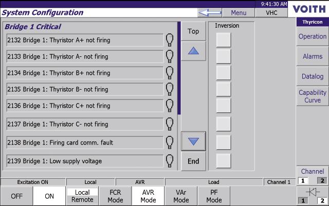
6 The alarm and event list are exportable as text files to USB or SSD cards directly from the Operator Panel. Digital Measuring Transducers Measuring of stator voltage and current is done by fast A / D conversions of each phase value several times per period. True RMS value is calculated by the measuring device. Automatic Voltage Regulator (AVR) The AVR control algorithm of PID characteristic regulates the stator voltage to the desired value. Field Current Regulator (FCR) Field Current Regulation fulfills the usual requirement of manual control. FCR is a backup to the AVR in case of e.g. fault in the stator voltage measuring circuits. Reactive Power Controller (VAr) The VAr controller keeps the reactive power constant. The reactive power is regulated by a slow operating three-state controller that adjusts the AVR s reference value. This maintains the favourable effects of the fast AVR during transient power line disturbances. Power Factor Controller (PF) The PF Controller keeps the power factor constant. The power factor is regulated by a slow operating three-state controller that adjusts the AVR s reference value. This maintains the favourable effects of the fast AVR during transient power line disturbances. Transfer between Control Modes The commutation between VAr Controller, PF Controller, AVR and FCR can be requested by the operator or is accomplished automatically in case of specific faults. Any transition is smooth, so there are no perceptible generator terminal voltage transients ( bumpless transition ) *. This includes for example: Field flashing, DC and/or AC Natural cooled or fan-cooled thyristor converter Redundant thyristor bridge (option) Auto adjustment of reactive power after synchronism Reactive load shedding before disconnection from the grid Pre-synchronizing Handling of external set points Selection of the control mode with follow-up and bumpless transfers Voltage Supervision The voltage measuring signal and the supply voltage to the rectifier bridge can be supervised by mutual comparison. At low measuring signal, automatic change-over to FCR is initiated. Fault Signal Indication Each individual internal and external fault signal is indicated in a local Human-Machine Interface. They can also be indicated with LEDs, relay contacts or on a remote control panel. The fault signals are grouped into Warning, Block or Trip ; these three signals are available via potential-free contacts. Warning and Block faults allow continuous operation, but a Block fault prevents restarting the Excitation System (i.e. field flash voltage missing). Self Monitoring and Diagnose The programmable logic controller self-monitoring functions cover the power supply system, processor, memories, I / O-units and communication system. Some of the alarms are time-delayed, and this is necessary to obtain a good voltage regulation during temporary network faults. Monitoring, Control and Supervision The regulator includes all necessary logical functions for control and supervision of the excitation equipment during start-up, service and shut-down. * Follow-up and bumpless transitions between control modes. 6
7 Limiters and Control Features Upon voltage changes in the power system, the AVR will restore the stator voltage by increasing or decreasing the excitation current of the machine, and thereby also the reactive power. The higher the short circuit power of the electrical system compared with the machine s, the higher the risk of overloading the generator; this due to high amounts of produced (overexcited) or consumed (under excited) reactive power. At unmanned stations, or when it is desired that the machine s contribution to maintaining the grid s voltage is not to be reduced, the need for limiters is increased. The limiters have the task of preventing outages of the machine due to operation of the protection relays caused by reactive overloading, underexcitation, or overloading of the exciter. Thyricon ensures the operation of the generator inside its capability curve 1,4 1,2 1,0 0,8 0,6 0,4 0,2-1,6-1,4-1,2-1,0-0,8-0,6-0,4-0,2 0 0,2 0,4 0,6 0,8 1,0 1,2 1,4 7
8 Reactive and Active Compensation or Droop In addition to the AVR structure, there are Reactive and Active Droop Compensators. These features compensate for active and reactive voltage drops in the step-up transformer and/or transmission line. The Reactive Droop Compensation also helps in balancing the reactive power among synchronous machines that are connected in parallel or directly to the grid without a transformer in between. Frequency Compensation Frequency Compensation is used to help weak grids during transients. The generator voltage is changed in phase with the deviation of the frequency. The changes in the active power delivered to the weak grid due to the voltage changes help to damp the oscillations. Volts per Hertz Limiter (V/Hz) The limiter, also called the flux limiter, reduces the voltage during under-frequency conditions. It protects the generating unit, especially the step-up transformer, against magnetic saturation. Time-delayed Overexcitation Limiter (OEL) The Time-delayed Overexcitation Limiter primarily avoids overheating of the synchronous machine field winding. The OEL also prevents overheating of the excitation system s power part. The permissible duration of the field current overload is inversely proportional to the overload current level. The OEL allows time-delayed overloads of the generator unit that are required for the stability of the electrical system. Instantaneous Overexcitation Limiter (OELf) The Instantaneous Overexcitation Limiter keeps the field current below a predetermined value. The OELf is mainly used to prevent the thyristor converter from overheating, because of its short thermal time constant. Underexcitation Limiter (UEL) The Underexcitation Limiter avoids operation conditions that would cause stator overheating or instability and loss of synchronism. The UEL action is determined by identified regions on the synchronous machine capability curve. The limiter region is programmed in the Thyricon s logic controller, and is coordinated with the loss of excitation function of the generator protection relay. Stator Current Limiter (SCL) Stator Overcurrent Limiter avoids overheating of the stator due to a rise in the generator current. SCL detects the overcurrent and compares it with the reactive current to determine how the voltage regulator should act. A time delay allows short overcurrents, providing space for the AVR and the PSS to act, and therefore increase the grid stability. The SCL is very convenient after upgrading of turbine runners where the active power output is significantly increased while the generator rated apparent power is unchanged. Safe operation of the Excitation System and of the generator guaranteed by the Thyricon limiters P SCL SCL UEL UEL OEL OEL f Q 8
9 Pre-synchronizing Pre-synchronizing means that the line (bus) voltage is used as a reference value for the voltage regulator during synchronizing. The voltage regulator will then keep the stator voltage equal to the line voltage during the synchronizing period. This facilitates synchronization and reduces VAr peaks when the generator breaker closes. Power System Stabilizer Thyricon features the dual-input integral of the accelerating power PSS2B described by the IEEE Standard. The PSS is not a limiter; it is an additional function that enhances the damping of low frequency oscillations on the synchronous machine. Such oscillations can be observed in the turbine speed, voltage frequency and active power. In order to identify the low frequency oscillations, the PSS2B synthesizes the integral of the accelerating power which is the net result of transient unbalances between the mechanical power delivered by the turbine to the generator, and the electrical power delivered by the generator to the power system. The PSS treats the integral of the accelerating power signal and introduces a disturbance into the Automatic Voltage Regulator PID controller. These PSS disturbances cause the damping of the low frequency oscillations. As a benefit of the action of several PSSs at several synchronous machines, the stability of the whole power system increases. Thyricon enhances the stability of the electrical system by the use the IEEE 421 dual input Power System Stabilizer (PSS2B) PSS max ƒ st w1 1+sT w1 st w sT 8 1+sT w2 1+sT w6 (1+sT 9 ) M + ( ) K s sT 1 1+sT 3 1+sT 10 1+sT 2 1+sT 4 1+sT 11 PSS K s3 PSS min P st w3 1+sT w3 st w4 1+sT w4 K s2 1+sT 7 Step response in the stator voltage and the resulting step in Q and the oscillation in active P 1,1 0,4 1,0 0,3 P [p.u.] U [p.u.] 0,9 0,8 0,2 0,1 Q [p.u.] 0,7 =U =P =Q 0,6-0, ,0 9


. The software modules are built up from function blocks from a library according to the Standard IEC 61131-1.")

10 1 2 Siemens AG 2013, Copyrights reserved 1 Graphical user friendly programming tool. 2 User friendly operator panel with touch sensitive colour LCD screen. Programmable Logic Controller PLC Thyricon s hardware platform is based on Programmable Logic Controllers, PLC. The PLC has an interface to the surroundings comprising digital and analogue inputs/outputs and communication units for serial communication. The equipment is normally mounted in a cubicle together with power supply units, transducers and interface relays. Application Software The software modules incorporated in the voltage regulator are structured to provide a very clear and detailed view of the modules included. All analogue signals are scaled in the per unit system (1 pu = 100 %). The software modules are built up from function blocks from a library according to the Standard IEC Examples of function blocks are AND-gates and SR-flip-flops, arithmetic blocks, control and filter blocks, timers and oscillators. The function blocks are interconnected to obtain the required functions in the program module. The function blocks contain parameter inputs for setting of gains, limit values, time delays etc. Siemens AG 2013, Copyrights reserved Siemens AG 2013, Copyrights reserved Industrial off-the-shelf programmable logic controllers guaranteeing worldwide access to maintenance and spare parts. Industrial off-the-shelf programmable logic controllers guaranteeing worldwide access to maintenance and spare parts. 10
11 Human-Machine Interface The voltage regulator can operate as a stand-alone unit with communication to all types of joint control and remote control equipment via parallel digital and analog signal interface. Series communication with different types of protocols can be included. The programmable logic controller takes care of the Excitation System and only a few input/output signals are needed. The standard Thyricon is fitted with the Siemens Touch Panel (Standard 12 screen), usually mounted in one of the cubicles front doors. The operator panel features a touch sensitive colour LCD screen. Typical input and output signals Excitation off / on Selection of mode of regulation AVR / VAr-controller / PF-controller Decrease / Increase signals for reference setting of the regulators Signal for closed generator circuit breaker Limiter in operation Common signal Warning Common signal Block Common signal Trip Different user levels with different passwords allow access to the different functions of the operator panel. As a safety precaution, Thyricon incorporates a command confirmation system. All frequently used commands that directly affect the status of the system are subject to a twostage operation sequence. Safety increased by a two-stage command confirmation system incorporated in the operator panel. 11


12

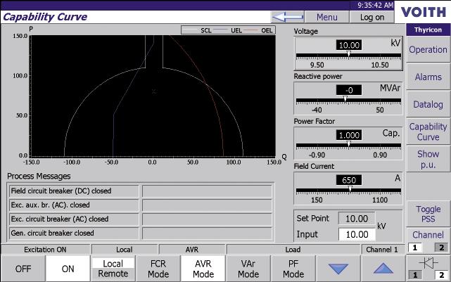
13 1 / 2 Powerful testing and maintenance tools incorporated in the operator panel. 3 Dynamic capability curve with the indication of the operation point and Thyricon limiters. 4 Parameter changing is accessible from the operator panel. 5 / 6 Built-in data logging and parameter changing from the operator panel allow the testing of the system without external loggers or computers. 7 7 PC based tool to retrieve, analyse, store and report the test results. User Friendly Operator Screen Thyricon user friendly human-machine interface provides information about the general status of the Excitation System and the measured generator data. Active control and operation mode, as well as the current state of the system, can be seen in the corresponding output fields. Local and Remote Interlocking of Commands Thyricon can be operated remotely from the control room or locally from the human-machine interface. The set points of the control modes can be locally changed, if necessary. Local and remote modes commands are safely interlocked so the maintenance staff is protected from dangerous remote commands during inspections and service. Monitoring and Forcing Values Thyricon incorporates powerful commissioning, testing and maintenance tools into the human-machine interface. Monitoring of digital and analogue inputs and alarms is accessible to all users. Forcing of input and output signals is protected by password. Block Diagram and Parameter Changing Thyricon parameters are accessible through the operator panel. The parameters are organized in self-explanatory groups. Accidental changes are avoided by minimum and maximum limits, command confirmation and/or password protection. Data Logging Thyricon s human-machine interface incorporates a powerful data logging tool. The number of samples, the sampling time and the number of analogue values to be logged are configurable. Various events and analogue values can be selected as trigger to the data logger. The data logging configuration is performed through the human-machine interface, but the actual data is stored in the PLC. Power outages will not destroy the last data trends stored. The data logging tool can be adjusted to permanently store the events related to the last emergency shut-down. The stored data can be viewed in the operator panel. The parameter changing and the data logging capabilities enable the commissioning of Thyricon without any external tool. The recorded analogue and digital values can be exported as text file to an USB or SSD card directly from the operator panel. The number of data logs stored in the PLC is limited. A PC-based software tool is available on request for retrieving, analysing, reporting and storing the data logs. 2 13
14 Static Excitation System Static exciters are used for synchronous generators in all types of power generating plants: hydro, thermal, gas, diesel and wind, as well as for synchronous condensers and motors. The advantages are summarized in the following main points: The excitation power is normally derived from the machine terminal bus and is conducted via the rectifier bridge into the field winding of the synchronous machine. Power necessary for voltage build-up at start is supplied via the field flashing equipment. Superior dynamic control characteristics Low losses The size is not dependent on the speed of the machine for a given excitation power The Power Circuit The main power circuits included in the Static Excitation System consist of: Excitation transformer Thyristor Rectifier Bridge Equipment for de-excitation Equipment for field flashing The excitation power can also be derived from the local power supply or from a suitable point outside the machine circuit breaker. As the connection point is normally energized, no field flashing equipment is required. During de-excitation, the field breaker is opened and the field of the machine is de-energized. High ceiling voltage capacity and a wide-range operating voltage of the firing card guarantee that Thyricon continues to work even during severe voltage drops in the electrical system. In most of the Static Excitation Systems, the rectifier bridge is fed by the generator itself. Digital Voltage Regulator U a, b, c PLC I a, b, c Exc. Transformer Field Flashing De-excitation Rectifier Bridge and Firing Card U a, b, c Generator 14

15 Example of a Thyricon Static Excitation System. Excitation Transformer The purpose of the Excitation Transformer is to adapt the power supply voltage to the converter and to isolate the field winding from the power supply. The secondary voltage is dimensioned according to the required ceiling voltage. The current rating of the transformer is determined by the maximum continuous field current of the synchronous machine. The transformer is normally dry of cast resin type. Temperature supervision by means of Pt100 elements can also be supplied. Thyristor Rectifier Bridge The converter, a fully controlled bridge, consists of a thyristor stack, firing card and the necessary equipment for supervision and cooling. Each thyristor stack is connected as a threephase, six-pulse bridge. This connection allows the converter to operate as a rectifier as well as an inverter. The thyristors are protected against short circuits by means of a quick-acting fuse in each branch or phase. Protection against voltage transients is achieved by RC circuits (snubbers). For efficient cooling, the thyristors are clamped into heat sinks that can be natural or forced air cooled (by ventilators). The thyristor converter is controlled by the digital voltage regulator via the firing card. This card converts the output signal from the regulator to trigger pulses, with correct phase shift compared with the supply voltage. The supply voltage is determined by the required ceiling voltage from the thyristor converter, and is adapted to machine data in each individual case. The ceiling voltage is critical for the speed of regulation of the generator voltage, and thereby the contribution from the generator to the voltage stability in the power line during disturbances. Typical ceiling voltage is 2.0 times the nominal field voltage. The thyristor converter is sized for the continuous field current necessary for maximum long-term load on the machine. It should also be able to carry the field forcing current received at ceiling voltage as described above. The normal field forcing time is 5 10 seconds. To achieve higher reliability, the excitation equipment can be supplied with redundant thyristor bridges. Redundancy is either performed as a system with one bridge in operation and the other one in hot stand-by or as an N + 1 system from which one bridge can be disconnected. In case of a system, each bridge is designed for rated load. In case of an N + 1 system, the bridges are designed for rated load with one bridge out of service. Field Flashing When the excitation equipment is supplied from the generator terminals, it is necessary to supply the field winding of the machine with a small current for a few seconds to initiate the voltage build-up. The special circuit for field flashing feeds about 5-10% of the no-load excitation current into the field winding until the voltage of the generator through the excitation transformer is sufficient to supply the converter. The start-up energy is normally provided by the station battery. Another solution available is to obtain the start-up energy from the station AC power supply via a transformer and a diode rectifier bridge. The wide-range operating voltage of the firing card practically enables Thyricon to start only with the remanent voltage. Nevertheless, field flashing is a must as the remanent voltage may be zero after long periods without operation. 15

16 De-excitation Special measures have to be taken to break the DC current and discharge the energy stored in the field winding of the machine. If not, very high voltages occur which can damage both the excitation equipment and the rotor winding. If a generator electrical fault should occur, it is also very important to de-excite the generator as fast as possible. Two different methods can be offered: De-excitation is performed by an excitation circuit breaker connected on the AC side of the converter, and a de-excitation thyristor connected in series with the de-excitation resistor on the DC side. De-excitation is performed by a field circuit breaker connected on the DC side of the converter, and a controlled thyristor discharge circuit. The breaker disconnects the rectifier from the field winding, and the discharge thyristor closes a circuit through the de-excitation resistor for the field current. Optionally, a make-before-break contact on the field breaker in parallel with the discharge thyristor ensures a safe de-excitation. Field Circuit Overvoltage Protection The purpose of the Field Overvoltage Protection (crowbar) is to prevent excessive voltages in the field circuit that might otherwise arise during certain unfavourable transient fault conditions, such as incorrect synchronization or loss of synchronism. The overvoltage protection is incorporated in the de-excitation equipment. It consists of two thyristors connected in antiparallel in series with the discharge resistor. The thyristors fires when the voltage in either direction across the field winding exceeds the protection level chosen with the triggering unit, and short-circuits the field winding through the discharge resistor. The resistor limits the de-excitation current and the resistance is calculated so that the voltage across the field does not exceed the maximum allowed level even at the highest induced field current occurring. Protection In addition to the protection for different parts of the main circuit described above, devices or relays protecting against the following are available: The de-excitation resistor can be delivered both as linear and non-linear type. The non-linear type is voltage dependant and de-excites the last third of the field energy faster than a linear resistor. De-excitation during normal unit shutdown is achieved by reversing the field voltage. The excitation breaker is opened when the field current is zero, saving the contact surfaces for unnecessary wear. Excitation transformer overcurrent / short circuit Temperature rises in the excitation transformer Rotor earth fault Overload in the field circuit Non-conducting thyristor branch Fan faullt Field circuit breaker from worldwide know manufacturers. Highly reliable cast-iron linear de-excitation resistors (top left). Non-linear resistors are also available. 16
17 Brushless Excitation System On smaller generating units, the static exciter is replaced by a direct-driven AC exciter machine with the rectifier mounted on the generator shaft. The main advantage of this solution compared to DC exciters, is that the problems associated with the commutator and brushes can be completely eliminated. The brushless system eliminates the slip rings and thus all currentcarrying brushes. The Brushless Excitation System is used for high speed synchronous machines with horizontal shaft, as well as for hydropower generators. The excitation power can also be derived from the local power supply or the generator terminal bus via a suitable transformer for isolating and voltage adaptation. With supply from the generator terminals, power for voltage build-up at start must be supplied via field flashing equipment. The controlled rectifier supplies adequate excitation power to the field winding of the synchronous generator. The rotating diode rectifier does not allow the main exciter to supply negative voltage or current to the generator field. The Power Circuit The main Power Circuits included in the Brushless excitation System consist of: Power supply Thyristor converter Main exciter The excitation power is normally derived from a PMG (a pilot AC exciter of permanent magnet type) and is conducted, via the controlled converter equipment, into the field winding of the main exciter. Typical diagram of a Brushless Excitation System During de-excitation, the exciter field breaker is opened and the field of the main exciter is de-energized through the discharge circuit. The field winding of the synchronous generator is then de-energized through the diode rectifier mounted on the generator shaft. Protection Common protections and supervisions which are available: Detection of diode faults in the rotating rectifier of the main exciter Protection against overload in the exciter field winding Earth fault protection. To be connected to an auxiliary slip ring in the main generator field Thyristor converter failure Digital Voltage Regulator U a, b, c I a, b, c Exc. Transformer Local Power Supply PLC Field Flashing De-excitation Rectifier Bridge and Firing Card Pilot Exciter U a, b, c Generator Exciter 17
18 Documentation and Quality Assurance The excitation system is described in a set of instructions and drawings: Function description Operation and maintenance instruction (including Troubleshooting guide) Cubicle mechanical layout Circuit diagram List of apparatus Test report The specification, design, manufacturing, testing and commissioning of the voltage regulator as well as the complete excitation system are executed under high quality standards and requirements. Prior to delivery each system is subjected to a test and verification procedure. The verification covers all the functions and units according to a pre-defined inspection and test plan. 18
19 Technical Data General data for control and regulation circuits. Concerning data for main circuit, please see specification available for the project. Technical Data Auxiliary supply voltage DC 24V or Vdc AC Vac Measuring circuits Voltage 1, 2 or 3 phases V Current, 1, 2 or 3 phases Frequency Load 1 or 5A 50 / 60 Hz < 0.1VA / phase Regulating accuracy < ± 0,5 % Ambient temperature Storage C Operation C Protection degree With self-cooled bridges Max. IP32 Environment conditions With forced cooling With air-water heat exchanger No condensation permitted Rodents and termite free Oil dust and carbon dust free up to 1000 m. a. s. l. Max. IP43 Max. IP54 Humidity < 85 % (higher humidity requires heaters and thermostats / hygrostats) Higher altitudes on request Thyristor bridge control Voltage interval V Frequency Hz Applicable codes IEEE Std Criteria and Definitions IEEE Std IEEE Std IEEE Std IEEE Std IEC (1991) Guide for Identification of Dynamic Performance Standard for High-Potential Test Requirements for Excitation Guide for the preparation of Excitation System Specification Excitation System Models for PSS-Studies Excitation Systems for Synchronous Machines 19
20 t3387en. Dimensions and illustrations without obligation. Subject to modifications. Voith Hydro Holding GmbH & Co. KG Alexanderstraße Heidenheim, Germany Tel Fax A Voith and Siemens Company
Excitation Systems RG3 - T4. Transistorized Excitation Systems for Synchronous Generators. Power Generation
 Excitation Systems RG3 - T4 Transistorized Excitation Systems for Synchronous Generators Power Generation Operating Characteristics Reliability High availability Digital control facilities Very good control
Excitation Systems THYRIPART. Compound-Excitation System for Synchronous Generators. Power Generation
 Excitation Systems Compound-Excitation System for Synchronous Generators Power Generation Operating Characteristics Load dependent Short circuit supporting Low voltage gradient dv/dt Black start capability
Excitation Systems. Service Generators SIPOL. Transistorized Excitation Systems for Synchronous Generators. Power Generation
 Excitation Systems Service Generators Transistorized Excitation Systems for Synchronous Generators Power Generation Operating Characteristics High availability Reliability Digital control facilities Very
P. O. BOX 269 HIGHLAND, ILLINOIS, U.S.A PHONE FAX
 SSE-N NEGATIVE FIELD FORCING SHUNT STATIC EXCITER/REGULATOR SYSTEM Control Chassis 6 SCR Power Chassis APPLICATION The SSE-N Negative Field Forcing Exciter/Regulator is used for both new and old installations
SPPA-E3000 Brushless Excitation System (BES, Type RG3)
") / Technical Description / Juni 2014 SPPA-E3000 Brushless Excitation System (BES, Type RG3) Maximum-availability excitation system for synchronous generators with brushless exciters Answers for energy.
/ Technical Description / Juni 2014 SPPA-E3000 Brushless Excitation System (BES, Type RG3) Maximum-availability excitation system for synchronous generators with brushless exciters Answers for energy.
APPLICATION: The heart of the system is a DSR 100 Digital Static Regulator used in conjunction with standard SCR based rectifier bridges.
 APPLICATION: Basler Electric offers a New Line of digitally controlled brush (static) or brushless excitation systems designed for use with existing Hydro, Gas as well as Diesel driven generators requiring
New Redundant Automatic Voltage Regulator (AVR) Solution
 Solution") White Paper New Redundant Automatic Voltage Regulator (AVR) Solution Author: David R. Brown, Turbomachinery Control Solutions Senior Consultant, Invensys Operations Management What s Inside: 1. Introduction
White Paper New Redundant Automatic Voltage Regulator (AVR) Solution Author: David R. Brown, Turbomachinery Control Solutions Senior Consultant, Invensys Operations Management What s Inside: 1. Introduction
Excitation systems and automatic voltage regulators
 ELEC0047 - Power system dynamics, control and stability Excitation systems and automatic voltage regulators Thierry Van Cutsem t.vancutsem@ulg.ac.be www.montefiore.ulg.ac.be/~vct November 2017 1 / 16 Overview
These drawings and single line diagrams provide an outlook of Basler Electric solutions for Excitation System installations and retrofit
 BSLER ELECTRIC DECS EXCITTION SYSTEMS For Retrofitting solutions and New installations These drawings and single line diagrams provide an outlook of Basler Electric solutions for Excitation System installations
Instrumentation, Controls & Electrical / Technical Description / February 2016
 / Technical Description / February 2016 SPPA-E3000 Static Excitation Systems (SES) Static excitation systems for excitation and voltage regulation of synchronous machines Answers for energy. Table of contents
DECS-200N-C1 Negative Forcing Digital Excitation Control System
 DECS-200N-C1 Negative Forcing Digital Excitation Control System The DECS-200N is a very compact Negative Forcing Digital Excitation Control System. This compact design accommodates 63 Vdc and 125 Vdc applications
SPECIFICATION, CONTROLS AND ACCESSORIES
 AS440 Automatic Voltage Regulator (AVR) SPECIFICATION, CONTROLS AND ACCESSORIES English Original Instructions A043Y697 (Issue 2) Table of Contents 1. DESCRIPTION... 1 2. SPECIFICATION... 3 3. CONTROLS...
System Protection and Control Subcommittee
 Power Plant and Transmission System Protection Coordination Reverse Power (32), Negative Sequence Current (46), Inadvertent Energizing (50/27), Stator Ground Fault (59GN/27TH), Generator Differential (87G),
E3 Adjustable Speed Drive Engineering Specification
 E3 Adjustable Speed Drive Engineering Specification PART 1 - GENERAL 1.0 Scope This specification shall cover Toshiba E3 AC Variable Frequency Drives, 6 pulse for 230V and 460V. 1.1 References A. National
EXCITATION SYSTEM MODELS OF GENERATORS OF BALTI AND EESTI POWER PLANTS
 Oil Shale, 2007, Vol. 24, No. 2 Special ISSN 0208-189X pp. 285 295 2007 Estonian Academy Publishers EXCITATION SYSTEM MODELS OF GENERATORS OF BALTI AND EESTI POWER PLANTS R. ATTIKAS *, H.TAMMOJA Department
FUJI Inverter. Standard Specifications
 FUJI Inverter o Standard Specifications Norminal applied motor The rated output of a general-purpose motor, stated in kw. That is used as a standard motor. Rated capacity The rating of an output capacity,
Fixed Series Compensation
 Fixed Series Compensation High-reliable turnkey services for fixed series compensation NR Electric Corporation The Fixed Series Compensation (FSC) solution is composed of NR's PCS-9570 FSC control and
T/3000 T/3000. Substation Maintenance and Commissioning Test Equipment
 T/3000 Substation Maintenance and Commissioning Test Equipment MULTI FUNCTION SYSTEM FOR TESTING SUBSTATION EQUIPMENT SUCH AS: CURRENT, VOLTAGE AND POWER TRANSFORMERS, ALL TYPE OF PROTECTION RELAYS, ENERGY
FEATURES. Custom-designed DIGITAL EXCITATION CONTROL SYSTEMS For synchronous generators. Digital Excitation Control Systems
 Custom-designed DIGITAL EXCITATION CONTROL SYSTEMS For synchronous generators Basler Electric engineers excitation systems to meet the specific needs of your power plant! More than 60 years of experience
S11 Adjustable Speed Drive Engineering Specification
 PART 1 - GENERAL 1.0 Scope This specification shall cover Toshiba S11 AC Variable Frequency Drives, 6 pulse for 3- phase 200-240VAC, 380-500VAC and single phase 200V to 240VAC. 1.1 References A. National
Dynamic Performance of an Excitation System Built in a Digital Way
 Dynamic Performance of an Excitation System Built in a Digital Way M.L. Orozco, H. Vásquez 1 Universidad del Valle, Escuela de Ingeniería Eléctrica y Electrónica, Cali, Colombia, email : maloroz@hotmail.com
ECE 422/522 Power System Operations & Planning/Power Systems Analysis II 5 - Reactive Power and Voltage Control
 ECE 422/522 Power System Operations & Planning/Power Systems Analysis II 5 - Reactive Power and Voltage Control Spring 2014 Instructor: Kai Sun 1 References Saadat s Chapters 12.6 ~12.7 Kundur s Sections
VFD - D700 Series Specifications. The latest low-cost variable speed control solution for centrifugal pumps.
 VFD - D700 Series Specifications The latest low-cost variable speed control solution for centrifugal pumps. Built-in PID Control to maintain pressure, flow, measured value, and much more 125% overload
SPECIFICATION, CONTROLS AND ACCESSORIES
 AS540 Automatic Voltage Regulator (AVR) SPECIFICATION, CONTROLS AND ACCESSORIES English Original Instructions A054N491 (Issue 1) Table of Contents 1. DESCRIPTION... 1 2. SPECIFICATION... 3 3. CONTROLS...
ECS2100 Excitation Control Systems
 ECS2100 Excitation Control Systems APPLICATION Basler Electric has expanded its excitation product offering with the addition of the ECS2100 excitation control system. The ECS2100 is a multi-microprocessor
VF-nC1 Adjustable Speed Drive Engineering Specification
 PART 1 - GENERAL 1.0 Scope This specification shall cover Toshiba VF-nC1 AC Variable Frequency Drives, 6 pulse for 100V single-phase 0.1 to 0.75kW, 200V single-phase 0.2 to 2.2kW and 200V threephase 0.1
N. TEST TEST DESCRIPTION
 Multi function system for testing substation equipment such as: current, voltage and power transformers, all type of protection relays, energy meters and transducers Primary injection testing capabilities
SECTION LOW VOLTAGE ACTIVE HARMONIC FILTER SYSTEM NEMA 1 ENCLOSED
 SECTION 16280 LOW VOLTAGE ACTIVE HARMONIC FILTER SYSTEM NEMA 1 ENCLOSED PART 1 - GENERAL 1.1 SUMMARY This specification defines the requirements for active harmonic filter systems in order to meet IEEE-519-2014
DIGITAL EXCITATION SYSTEM PROVIDES ENHANCED PERFORMANCE AND IMPROVED DIAGNOSTICS
 DIGITAL EXCITATION SYSTEM PROVIDES ENHANCED PERFORMANCE AND IMPROVED DIAGNOSTICS C. Allan Morse Member, IEEE Eaton / Cutler Hammer 221 Heywood Road Arden, NC 2874 C. Richard Mummert Member, IEEE Eaton
2.4 Modeling on reactive power or voltage control. Saadat s Chapters Kundur s Chapters 5.4, 8 and 11.2 EPRI Tutorial s Chapter 5
 2.4 Modeling on reactive power or voltage control Saadat s Chapters 12.6 12.7 Kundur s Chapters 5.4, 8 and 11.2 EPRI Tutorial s Chapter 5 1 Objectives of Reactive Power and Voltage Control Equipment security:
WDG 13 - Technical Data Sheet
 LV 804 T WDG 13 - Technical Data Sheet FRAME LV 804 T SPECIFICATIONS & OPTIONS STANDARDS Cummins Generator Technologies industrial generators meet the requirements of BS EN 60034 and the relevant sections
N. TEST TEST DESCRIPTION
 Multi function system for testing substation equipment such as: current, voltage and power transformers, over-current protection relays, energy meters and transducers Primary injection testing capabilities
WDG 12 - Technical Data Sheet
 LV 804 T WDG 12 - Technical Data Sheet FRAME LV 804 T SPECIFICATIONS & OPTIONS STANDARDS Cummins Generator Technologies industrial generators meet the requirements of BS EN 60034 and the relevant sections
Instructions AVC125-10: Voltage Regulator. Voltage Range. Maximum Continuous Burden. Voltage Range. Nominal Frequency
 www.basler.com + 68.654.234 (USA) info@basler.com Model Description AVC25-0 Voltage Regulator INTRODUCTION The AVC63-2 and AVC25-0 regulate the level of excitation supplied to the field of a conventional,
WDG 71 - Technical Data Sheet
 HV 804 R WDG 71 - Technical Data Sheet FRAME HV 804 R SPECIFICATIONS & OPTIONS STANDARDS Cummins Generator Technologies industrial generators meet the requirements of BS EN 60034 and the relevant sections
T 1000 PLUS. Secondary Injection Relay Test Set. Designed for testing relays and transducers
 Secondary Injection Relay Test Set Designed for testing relays and transducers Microprocessor controlled With phase angle shifter Frequency generator Test results and settings are saved into local memory
WDG 12 - Technical Data Sheet
 LV 804 S WDG 12 - Technical Data Sheet FRAME LV 804 S SPECIFICATIONS & OPTIONS STANDARDS Cummins Generator Technologies industrial generators meet the requirements of BS EN 60034 and the relevant sections
WDG 83 - Technical Data Sheet
 HV 804 R WDG 83 - Technical Data Sheet FRAME HV 804 R SPECIFICATIONS & OPTIONS STANDARDS STAMFORD AC generators are designed to meet the performance requirements of IEC EN 60034-1. Other international
D I G I T A L V O L T A G E R E G U L A T O R
 The Cat Digital Voltage Regulator is a microprocessor based control designed to provide precise voltage control, robust transient response, and generator protection with industry leading features and versatility.
A Subsidiary of Regal-Beloit Corporation. AC Inverter Terminology
 AP200-9/01 Acceleration The rate of change in velocity as a function of time. Acceleration usually refers to increasing velocity and deceleration to decreasing velocity. Acceleration Boost During acceleration,
TD 1000 PLUS. Secondary Injection Relay Test Set. Designed for testing relays and transducers
 Secondary Injection Relay Test Set Designed for testing relays and transducers Two current outputs to test differential relays Convertible current and voltage generator With phase angle shifter Frequency
RETROFITTING. Motor Protection Relay. Two mountings are available, Flush Rear Connection (EDPAR) or Projecting Rear Connection (SDPAR).
 or Projecting Rear Connection (SDPAR).") RETROFITTING Motor Protection Relay NPM800R (R2 case) and NPM800RE (R3 case) are dedicated to the refurbishment of 7000 series (R2 and R3 cases) of CEE relays providing the protection of medium voltage
RETROFITTING Motor Protection Relay NPM800R (R2 case) and NPM800RE (R3 case) are dedicated to the refurbishment of 7000 series (R2 and R3 cases) of CEE relays providing the protection of medium voltage
R180. AVRs. Installation and maintenance
 This manual concerns the alternator AVR which you have just purchased. We wish to draw your attention to the contents of this maintenance manual. SAFETY MEASURES Before using your machine for the first
WDG 12 - Technical Data Sheet
 LV 804 W WDG 12 - Technical Data Sheet FRAME LV 804 W SPECIFICATIONS & OPTIONS STANDARDS STAMFORD AC generators are designed to meet the performance requirements of IEC EN 60034-1. Other international
WDG 12 - Technical Data Sheet
 LV 804 R WDG 12 - Technical Data Sheet FRAME LV 804 R SPECIFICATIONS & OPTIONS STANDARDS STAMFORD AC generators are designed to meet the performance requirements of IEC EN 60034-1. Other international
Power Supply Unit (550W)
") Contents Power Supply Unit (550W) Chapter 3.1 GENERAL DESCRIPTION...3.1-1 APPLIED VOLTAGE...3.1-2 INPUT CURRENT...3.1-2 DC OUTPUT...3.1-3 VOLTAGE DROPOUT...3.1-4 OUTPUT ISOLATION...3.1-4 OVERLOAD/UNDERLOAD
Contents Power Supply Unit (550W) Chapter 3.1 GENERAL DESCRIPTION...3.1-1 APPLIED VOLTAGE...3.1-2 INPUT CURRENT...3.1-2 DC OUTPUT...3.1-3 VOLTAGE DROPOUT...3.1-4 OUTPUT ISOLATION...3.1-4 OVERLOAD/UNDERLOAD
ELECTRONIC CONTROL OF A.C. MOTORS
 CONTENTS C H A P T E R46 Learning Objectives es Classes of Electronic AC Drives Variable Frequency Speed Control of a SCIM Variable Voltage Speed Control of a SCIM Chopper Speed Control of a WRIM Electronic
WDG 07 - Technical Data Sheet
 LV 804 S WDG 07 - Technical Data Sheet FRAME LV 804 S SPECIFICATIONS & OPTIONS STANDARDS Cummins Generator Technologies industrial generators meet the requirements of BS EN 60034 and the relevant sections
McPherson Voltage Regulators 4501 NW 27 Ave Miami FL
 McPherson Voltage Regulators 4501 NW 27 Ave Miami FL 33142 305-634-1511 To avoid of possible personal injury or equipment damage read and understand this manual before installation. (A.V.R) 208 / 380 /
M40FA640A/A - Mark I. User Manual SIN.NT Automatic Voltage Regulator for Three-phase Synchronous Generators. (Issued: 04.
 M40FA640A/A - Mark I User Manual Automatic Voltage Regulator for Three-phase Synchronous Generators (Issued: 04.2010) SIN.NT.015.6 Instruction Manual Installation Operation Maintenance MARELLI AVR M40FA640A
WDG 61 - Technical Data Sheet
 HV 804 W WDG 61 - Technical Data Sheet FRAME HV 804 W SPECIFICATIONS & OPTIONS STANDARDS STAMFORD AC generators are designed to meet the performance requirements of IEC EN 60034-1. Other international
Power Plant and Transmission System Protection Coordination of-field (40) and Out-of. of-step Protection (78)
 and Out-of. of-step Protection (78)") Power Plant and Transmission System Protection Coordination Loss-of of-field (40) and Out-of of-step Protection (78) System Protection and Control Subcommittee Protection Coordination Workshop Phoenix,
Power Plant and Transmission System Protection Coordination Loss-of of-field (40) and Out-of of-step Protection (78) System Protection and Control Subcommittee Protection Coordination Workshop Phoenix,
Magnetization System of Magnetically Controlled Shunt Reactors
 Magnetization System of Magnetically Controlled Shunt Reactors Leonid Kontorovych, Technical Director of ZTR PJSC, PH.D. in Engineering Sciences; Igor Shyrokov, head of the department of reactors control
Variable Frequency Drive / Inverter (0.4 ~ 280kW)
") Variable Frequency Drive / Inverter (0.4 ~ 280kW) & Standard Features Configuration Comparison Comparison Table Enclosure IP00 IP20 NEMA 1 Rating Single phase 0.4 2.2kW 0.4 1.5kW Three phase 0.4 4kW Constant
Variable Frequency Drive / Inverter (0.4 ~ 280kW) & Standard Features Configuration Comparison Comparison Table Enclosure IP00 IP20 NEMA 1 Rating Single phase 0.4 2.2kW 0.4 1.5kW Three phase 0.4 4kW Constant
Industrial Electrician Level 3
 Industrial Electrician Level 3 Industrial Electrician Unit: C1 Industrial Electrical Code I Level: Three Duration: 77 hours Theory: Practical: 77 hours 0 hours Overview: This unit is designed to provide
T 1000 PLUS Secondary Injection Relay Test Set
 Secondary Injection Relay Test Set Designed for testing relays and transducers Microprocessor controlled With phase angle shifter Frequency generator Test results and settings are saved into local memory
Orbital GFI Inverter Series
 Orbital GFI Inverter Series Datasheet Key Features One, split or three phases and up to 25 kva Superior efficiency of 95% CAN Bus control and DAQ Power quality and EMC compliance in accordance with European
WDG 51 - Technical Data Sheet
 MV 804 S WDG 51 - Technical Data Sheet FRAME MV 804 S SPECIFICATIONS & OPTIONS STANDARDS STAMFORD AC generators are designed to meet the performance requirements of IEC EN 60034-1. Other international
Generator Protection GENERATOR CONTROL AND PROTECTION
 Generator Protection Generator Protection Introduction Device Numbers Symmetrical Components Fault Current Behavior Generator Grounding Stator Phase Fault (87G) Field Ground Fault (64F) Stator Ground Fault
VOLTAGE REGULATOR R 449. Installation and maintenance. This manual must be sent to the end user R 449 X2 Z1 X1 Z2 E+ E- (12V - 10A)
") This manual must be sent to the end user X2 Z1 X1 Z2 E+ E- J1 t (12V - 10A) ~ 10 ohms Exciter field + - Isolated DC power supply Installation and maintenance WARNING TO AVOID HARM EITHER TO PEOPLE OR TO
This manual must be sent to the end user X2 Z1 X1 Z2 E+ E- J1 t (12V - 10A) ~ 10 ohms Exciter field + - Isolated DC power supply Installation and maintenance WARNING TO AVOID HARM EITHER TO PEOPLE OR TO
System Protection and Control Subcommittee
 Power Plant and Transmission System Protection Coordination Volts Per Hertz (24), Undervoltage (27), Overvoltage (59), and Under/Overfrequency (81) Protection System Protection and Control Subcommittee
T 1000 PLUS. Secondary Injection Relay Test Set. Designed for testing relays and transducers
 Secondary Injection Relay Test Set Designed for testing relays and transducers Microprocessor controlled With phase angle shifter Frequency generator High power outputs Large graphical display Compact
NORTH CAROLINA INTERCONNECTION REQUEST. Utility: Designated Contact Person: Address: Telephone Number: Address:
 NORTH CAROLINA INTERCONNECTION REQUEST Utility: Designated Contact Person: Address: Telephone Number: Fax: E-Mail Address: An is considered complete when it provides all applicable and correct information
VOLTAGE STABILITY OF THE NORDIC TEST SYSTEM
 1 VOLTAGE STABILITY OF THE NORDIC TEST SYSTEM Thierry Van Cutsem Department of Electrical and Computer Engineering University of Liège, Belgium Modified version of a presentation at the IEEE PES General
Sequence Networks p. 26 Sequence Network Connections and Voltages p. 27 Network Connections for Fault and General Unbalances p. 28 Sequence Network
 Preface p. iii Introduction and General Philosophies p. 1 Introduction p. 1 Classification of Relays p. 1 Analog/Digital/Numerical p. 2 Protective Relaying Systems and Their Design p. 2 Design Criteria
Power Plant and Transmission System Protection Coordination Fundamentals
 Power Plant and Transmission System Protection Coordination Fundamentals NERC Protection Coordination Webinar Series June 2, 2010 Jon Gardell Agenda 2 Objective Introduction to Protection Generator and
SPECIFICATION, CONTROLS AND ACCESSORIES
 MX341 Automatic Voltage Regulator (AVR) SPECIFICATION, CONTROLS AND ACCESSORIES English Original Instructions A043Y699 (Issue 2) Table of Contents 1. DESCRIPTION... 1 2. SPECIFICATION... 3 3. CONTROLS...
Index 2. G Gain settings 4 31 Glossary of terms A 2 Grommets 2 13
 Index A A Group functions 3 9 AC reactors 5 3 Acceleration 1 15, 3 8 characteristic curves 3 26 second function 3 24 two-stage 4 19 Acceleration stop function 3 21 Access levels 3 5, 3 36, 4 25 Access
Highgate Converter Overview. Prepared by Joshua Burroughs & Jeff Carrara IEEE PES
 Highgate Converter Overview Prepared by Joshua Burroughs & Jeff Carrara IEEE PES Highgate Converter Abstract Introduction to HVDC Background on Highgate Operation and Control schemes of Highgate 22 Why
4Q POWER AMPLIFIERS AC AND DC 3000VA 3x3000VA
 PERFORMANCES High accuracy High stability Fast transients High inrush current facilities Wide bandwidth 25 khz at -3dB Internal waveform DC and up to 10 khz Very low distortion Quadrant change without
HPVFP High Performance Full Function Vector Frequency Inverter
 Advanced User Manual HPVFP High Performance Full Function Vector Frequency Inverter HP VER 1.00 1. HPVFP Parameter Set Overview...3 1.1. About this section...3 1.2. Parameter Structure Overview...3 1.3.
NERC Protection Coordination Webinar Series July 15, Jon Gardell
 Power Plant and Transmission System Protection Coordination Reverse Power (32), Negative Sequence Current (46), Inadvertent Energizing (50/27), Stator Ground Fault (59GN/27TH), Generator Differential (87G),
Operating Instructions
 4XH35QB151210 Small General Frequency Converter Operating Instructions 220V 0.75KW 5.5KW 400V 0.75KW 15KW Please read the instruction carefully and understand the contents so that it can be installed and
The new Yaskawa Varispeed G7 Inverter
 The new Yaskawa Varispeed G7 Inverter Unique new 3-level PWM flux vector Constant or variable torque applications control method 0.4 kw to 300 kw power range Exceptional low speed/high torque control Quick
ESB National Grid Transmission Planning Criteria
 ESB National Grid Transmission Planning Criteria 1 General Principles 1.1 Objective The specific function of transmission planning is to ensure the co-ordinated development of a reliable, efficient, and
TOSHIBA International Corp
 TOSHIBA International Corp GUIDE SPECIFICATIONS THREE PHASE UNINTERRUPTIBLE POWER SYSTEM TOSHIBA 4200FA 30 kva CT Internal Battery UPS GUIDE SPECIFICATIONS 1 (30 kva CT) 1.0 SCOPE 1.1 System This specification
PI734F - Winding 28. Technical Data Sheet APPROVED DOCUMENT
 - Winding 28 Technical Data Sheet SPECIFICATIONS & OPTIONS STANDARDS Stamford industrial generators meet the requirements of BS EN 60034 and the relevant sections of other national and international standards
Table of Contents. Introduction... 1
 Table of Contents Introduction... 1 1 Connection Impact Assessment Initial Review... 2 1.1 Facility Design Overview... 2 1.1.1 Single Line Diagram ( SLD )... 2 1.1.2 Point of Disconnection - Safety...
R 450. AVRs. Installation and maintenance. This manual is to be given to. the end user R 450 VOLT. STAB. I EXC STAT. LEDS PMG
 6 5 4 7 8 9 C US 45 en -. / e 5 Hz EXT FREQ 6 Hz SETTING This manual is to be given to the end user VOLT. STAB. I EXC FUSIBLES / FUSES EXT.FREQ. SET. ON ONLY FOR SPECIAL CONFIG. KNEE 5Hz 65Hz 6Hz PHASE
Exercise 3. Doubly-Fed Induction Generators EXERCISE OBJECTIVE DISCUSSION OUTLINE DISCUSSION. Doubly-fed induction generator operation
 Exercise 3 Doubly-Fed Induction Generators EXERCISE OBJECTIVE hen you have completed this exercise, you will be familiar with the operation of three-phase wound-rotor induction machines used as doubly-fed
EE171. H.H. Sheikh Sultan Tower (0) Floor Corniche Street Abu Dhabi U.A.E
 Floor Corniche Street Abu Dhabi U.A.E") EE171 Electrical Equipment & Control System: Electrical Maintenance Transformers, Motors, Variable Speed Drives, Generators, Circuit Breakers, Switchgears & Protective Systems H.H. Sheikh Sultan Tower
EE171 Electrical Equipment & Control System: Electrical Maintenance Transformers, Motors, Variable Speed Drives, Generators, Circuit Breakers, Switchgears & Protective Systems H.H. Sheikh Sultan Tower
Type of loads Active load torque: - Passive load torque :-
 Type of loads Active load torque: - Active torques continues to act in the same direction irrespective of the direction of the drive. e.g. gravitational force or deformation in elastic bodies. Passive
Development of an Experimental Rig for Doubly-Fed Induction Generator based Wind Turbine
 Development of an Experimental Rig for Doubly-Fed Induction Generator based Wind Turbine T. Neumann, C. Feltes, I. Erlich University Duisburg-Essen Institute of Electrical Power Systems Bismarckstr. 81,
r 450 Installation and maintenance This manual is to be given to the end user R 450 VOLT. STAB. I EXC STAT. AREP PMG FUSIBLES / FUSES
 8 7 9 6 5 4 C 45 en -. / a R 45 DETECT. PH PH. SENSING 5 Hz EXT FREQ 6 Hz SETTING This manual is to be given to the end user VOLT. STAB. I EXC FUSIBLES / FUSES EXT.FREQ. SET. ON ONLY FOR SPECIAL CONFIG.
Generator Operation with Speed and Voltage Regulation
 Exercise 3 Generator Operation with Speed and Voltage Regulation EXERCISE OBJECTIVE When you have completed this exercise, you will be familiar with the speed governor and automatic voltage regulator used
Numbering System for Protective Devices, Control and Indication Devices for Power Systems
 Appendix C Numbering System for Protective Devices, Control and Indication Devices for Power Systems C.1 APPLICATION OF PROTECTIVE RELAYS, CONTROL AND ALARM DEVICES FOR POWER SYSTEM CIRCUITS The requirements
PARAMETER LIST PARAMETER LIST
 PRMETER LIST PRMETER LIST dvanced Genset Controller, GC 200 larm list Parameter list Document no.: 489340605L SW version 4.2.x or later GC 200 parameter list 489340605 UK Contents: General information...
NTG MULTIFUNCTON GENERATOR PROTECTION RELAY. NTG-Slide
 NTG MULTIFUNCTON GENERATOR PROTECTION RELAY 1 NTG Digital protection relay that integrates a number of functions required r for the protection of generators. It is used in power stations from gas, steam,
Meduim Voltage Drives
 YANTRA HARVEST Meduim Voltage Drives YANTRA HARVEST ENERGY PVT. LTD. Office No. 101, 102, 103, Plot No. 84, Survey No. 40, Ambedkar Road, Sangamwadi, Near RTO Office, Pune - 411001 (India) Tel / Fax :
TMdrive -XL Series Family Product Application Guide. solar inverters. power generation
 TMdrive -XL Series Family Product Application Guide metals cranes mining testing oil & gas solar inverters power generation cement TMdrive-XL Series 8 MVA 15 MVA 20 MVA 30 MVA The TMdrive XL series family
ADJUSTABLE SPEED DRIVES. W7 Series. 18 Pulse
 ADJUSTABLE SPEED DRIVES W7 Series 18 Pulse Meets or Exceeds Your Specifications Standard Specifications Item Voltage Class 460V Maximum HP 60 75 100 125 150 200 250 300 400 500 600 700 800 Drive Rating
PI734F - Winding 07. Technical Data Sheet APPROVED DOCUMENT
 - Winding 07 Technical Data Sheet SPECIFICATIONS & OPTIONS STANDARDS Stamford industrial generators meet the requirements of BS EN 34 and the relevant sections of other national and international standards
POWER AMPLIFIERS 4 QUADRANTS 3x500 VA to 3x1500 VA - THREE-PHASES
 PERFORMANCES High accuracy High stability Fast transients High inrush current facilities Wide bandwidth Very low distortion Quadrant change without transition Very low output impedance Low noise RS232
ADC5000 SERIES. AC/DC Switch Mode Power Supplies and Rectifiers for Industrial and Telecom Applications. 60W, 125W and 250 W
 ADC5000 SERIES AC/DC Switch Mode Power Supplies and Rectifiers for Industrial and Telecom Applications 60W, 125W and 250 W Input voltage 230/115 VAC voltages 12, 24, 36 or 48 VDC Statistical MTBF >3 000
Sizing Generators for Leading Power Factor
 Sizing Generators for Leading Power Factor Allen Windhorn Kato Engineering 24 February, 2014 Generator Operation with a Leading Power Factor Generators operating with a leading power factor may experience
R438 A.V.R. Installation and maintenance. This manual is to be given to. the end user CALL US TODAY POWER-58. SHOP ONLINE
 T1 T7 T2 T8 This manual is to be given to the end user T4 T10 140 mm T5 T11 X2 Z1X1 Z2 E+ E- 0V 110 220 380 200 mm z P1 ST9 AREP PMG This manual concerns the alternator which you have just purchased. We
Issued: September 2, 2014 Effective: October 3, 2014 WN U-60 Attachment C to Schedule 152, Page 1 PUGET SOUND ENERGY
 WN U-60 Attachment C to Schedule 152, Page 1 SCHEDULE 152 APPLICATION FOR INTERCONNECTING A GENERATING FACILITY TIER 2 OR TIER 3 This Application is considered complete when it provides all applicable
A.V.R. R250. Installation and maintenance R250 0V E+ E- VOLT STAB FREQ. & L.A.M. CONFIG. REQUEST A QUOTE
 110 0V E+ E- VOLT STAB KNEE 47.5Hz OFF 9 SPECIAL 8 KNEE 65Hz 7 OFF KNEE 6 57Hz OFF 7 8 50Hz o 9 0 5 6 1 2 3 4 OFF 1 13% 2 25% 3 OFF 4 13% 5 25% 60Hz FREQ. & L.A.M. CONFIG. This manual concerns the alternator
Modern transformer relays include a comprehensive set of protective elements to protect transformers from faults and abnormal operating conditions
 1 Transmission transformers are important links in the bulk power system. They allow transfer of power from generation centers, up to the high-voltage grid, and to bulk electric substations for distribution
Improve asset protection and utilization
 QUALITROL 509 ITM Intelligent transformer monitor Improve asset protection and utilization Immediately know your transformer health with TransLife Optimize loading and equipment life Simplify root cause