Clocking a TD-04 Turbo Compressor Housing. Appendix A : AWIC Silicone and Tubing Fitting
|
|
|
- Kelly Thomasina French
- 5 years ago
- Views:
Transcription


1 Clocking a TD-04 Turbo Compressor Housing Appendix A : AWIC Silicone and Tubing Fitting Revision A:
2 Tools: Metric Sockets (10, 12, 14, 17mm) 5mm Hex Key Large Internal Snap Ring Pliers 3/8 Socket Extension Wrenches and Adjustable Wrench.1015 Drill Bit (#39, or similar) Large Phillips Screwdriver Electric Drill Bench Mounted Vice PB Blaster File Ruler Optional Tools: Aluminum Vice Jaws ¼ and 11/32 Drill Bit 1/8-27 NPT Tap Flapper Wheel Die Grinder Bench Mounted Belt Sander Small Hammer Small Punch Small Center Drill Quick Clamp Vernier Calipers Parts: Zero Decibel Motorsports 70deg Clocking Bracket 3X 8mm Button Head Cap Screws 1X 8mm Lock Washer 1X 8mm Nut with Integrated Star Lock Washer High Temp Silicone (or optional oil drain gasket) Copper Sealing Washers Optional: 1/8 NPT to Barb Fitting Optional: Oil Drain Gasket
3 Preparation: Clean off the turbo using compressed air to remove all dirt, dust, and rust. Pay special attention to the center housing where the water lines and snap ring are as this area will have the most loose rust. Create a clean work area free of contamination and objects that could fall onto the turbo. 1: Remove Water Lines Use a 17mm socket to remove both banjo bolts that secure water lines. Remove all 4 copper washers (lower washers may stick to housing).
4 2: Separate Water Lines After the water lines have been removed, flex the two pipes to break apart the tab connecting them in the middle. Remove the remainder of the tab using a belt sander or file. This is done to allow the water lines to be adjusted independently for improved clearance as necessary. 3: Remove Oil Drain Use a 10mm socket with an extension to remove the two bolts. Tube may stick to the gasket. If you plan to use a new gasket, scrap the old gasket off. If you plan to reuse the gasket along with a thin layer of silicone be careful not to tear the gasket beyond what the silicone can repair.
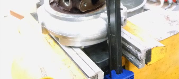
5 4: Remove Wastegate Remove the two bolts with lock washers holding the wastegate bracket to the turbo. You may choose to remove the e-clip on the flapper arm or leave it in place and let the wastegate dangle. 5: Remove Snap Ring Place the turbo into the vice with the exhaust housing facing upwards. Clamp on the neck of the compressor inlet. Ensure all loose rust is removed from the snap ring area and spray some PB Blaster onto the ring and allow a few minutes for it to penetrate. Using the snap ring pliers attempt to loosen the snap ring. If it is stuck, using a small hammer and punch can help to free it. Do not use excessive force. The snap ring has a tapered outside that pulls the compressor housing onto the center housing and puts a lot of pressure onto the ring and housing. Using a pair of quick clamps to pull the compressor housing closer to the exhaust housing can relieve some pressure on snap ring. Snap ring pliers with a lock on them are useful to give you time to work and rest without needing to maintain a constant grip on the pliers.


6
7 6: Separate Turbo Gently rock the exhaust housing while pulling up. There is a dowel pin in the compressor housing that will prevent you from rotating the two parts relative to each other. There is a large o-ring mounted on the center housing that adds drag as the compressor housing is coming apart. If necessary, use a small hammer to gently tap upwards on opposing sides of the exhaust housing. Do not use excessive force or tap only on a single location. Once the two parts are separated remove the compressor housing from the vice place the exhaust housing in the vice clamping on two of the studs. 7: Drill New Dowel Pin Locating Hole There is a dowel pin pressed into the compressor housing that keys with a hole in the center housing to ensure proper alignment of the compressor outlet. This dowel pin can either be pulled out or ground down or, the preferred method, is to drill a new hole. With the existing hole positioned on the left, make a mark on the flange of the center housing that is from the center of the existing hole. This does not need to be perfect. It is recommended to use a center drill to start the hole as they are not prone to wandering like a drill bit. Start the hole on the previously created mark centering it on the flange. A perfectly located hole can be as small as.078 (2mm). It is easier to use a larger drill bit and allow for some misalignment. Drill slowly using light using light pressure stopping often to clear off chips and check progress. If the drill bit snaps or breaks through the flange unexpectedly the drill can damage the fins on the compressor wheel if you are pushing too hard. This is why it is important to use light pressure and proceed slowly. Place the compressor housing onto the center housing and check that the dowel pin is able to fit in the hole. If it is not, then use the next larger drill until the dowel pin and hole are able to mesh together. Repeat as necessary. After this is completed, set the exhaust housing aside.
8
9 8: Remove Oil Feed Line Mounting Boss With the housing clocked, the boss is no longer in the correct position and not needed. It interferes with the lower water line and must be removed. Simply cut it off with a saw or file it down. Do not remove the boss with the larger 8mm threaded hole completely, but round off the square edge. Round off this edge Remove this Keep this 9: Optional: NPT Compressor Fitting and PnP Outlet These steps are not required but can only be performed with the turbo separated. Instead of using the OEM steel nipple that is pressed into the housing you may wish to replace it with a threaded brass fitting (either straight or angled). Simply bend the fitting to snap it off and file or belt sand any remainder flush with the aluminum housing. Use a ¼ drill bit to remove the embedded portion of the nipple. Follow up with an 11/32 drill (1/8 NPT pilot drill size). Tap the hole with an NPT tap stopping often to check the fitment of the NPT fitting. NPT threads are tapered and tapping too deep will make the top of the hole too large and the fitting won t be able to seat properly. In addition to the fitting, you may port and polish the outlet of the compressor housing. Use various flapper wheels to smooth out the semi-rough casting and taper the outlet. After completing this step blow the housing out with compressed air and run water through it for several minutes ensuring all traces of metal have been removed.
10

11 10: Reassemble Compressor and Center Housing/Exhaust Housing Place the compressor housing into the vice in the same manner as when the turbo was separated. Carefully place the center housing onto the compressor housing being mindful of the fins on the wheel. Make sure the dowel pin and the hole line up. At this point the quick clamp can be used again to pull the two parts of the turbo together in the same manner as it was used to help separate the turbo previously. Squeeze the snap ring together and insert it into the groove in the compressor housing starting the end opposite the open end of the ring. Rotate the compressor wheel by hand to ensure it rotates freely and does not scrape anything.


12 11: Reattach Oil Drain Reattach the drain using a new gasket or high temp silicone on the old gasket. This is a low pressure return line. Pay attention to the orientation of the line as it is not symmetrical. It should bend away from the compressor housing. 12: Attach Clocking Bracket Place the bracket in between the exhaust housing and the integrated wastegate bracket. Place an 8mm bolt through the clocking bracket and the nut with the integrated washer on the backside of the integrated wastegate bracket on the hole at the fat end of the bracket. Put a second bolt through the middle hole of the clocking bracket and the integrated bracket and thread it into the hole on the compressor housing. The integrated bracket will sit against the compressor housing. The last hole requires the split lock washer in between the housing and the clocking bracket. Tighten all of the bolts fully. Note Stacking Order Lock Washer
13 13: Check Waste Gate Arm Depending on the tolerances of the parts used the wastegate arm can come very close to the opening in the wastegate housing. If it rubs use a small file to provide the necessary clearance. After ensuring it doesn t rub, check the wastegate flapper. It should be pulled tight against the exhaust housing. If it is not tight, remove the e-clip (if it wasn t previously), loosen the locking nut, and adjust the bracket on the end of the arm in ½ turn increments. After each ½ turn, fit the arm back over the flapper and check to see if it is pulled tight against the housing. Once it is tight, retighten the locking nut.
14 14: Water Lines The water lines will need to be tweaked for better clearance with the rotated housing. This is best done by placing the water lines in a vice, placing a 3/8 extension through the banjo bolt hole and bending it. It does not need to bend very far! Bend in small increments and test the fitment. The upper water line gets rotated slightly with the lower line gets bent outwards to clear the boss next to where the oil line boss used to be. Make sure when checking fitment that you put the copper washers in place as this will change the clearance. 15: Test Fit and Oil Line Place the turbo onto the uppipe. The lower water line may need to be bent towards the front of the car to clear the bracket holding the uppipe to the engine. The turbo line may also need to be bent for additional clearance. To bend water lines after they are installed, insert a large Phillips screwdriver into the open end of the tube for extra leverage.
15 Appendix A: AWIC Silicone and Aluminum Piping Fitment The following section details the setup when using a clocked turbo for an AWIC on a FFR 818. This specific setup will also work if installing a clocked turbo and type 14 AWIC core onto a Subaru. 1: Silicone Placement Place a 1.75 to 2.5 x 90deg coupler onto the outlet of the turbo and a 3.0 to 2.5 x 90deg coupler onto the inlet of the AWIC core as shown in the photo below.
16 2: Mark and Cut Aluminum Place a 2.5 x1 x 45deg aluminum pipe on top of the silicone couplers. Change the alignment of the couplers until it lines up well with the pipe. Make a mark on the pipe at the point where the coupler is still straight. Cut the aluminum pipe and deburr both the inside and outside.
17 3: Test Fit Remove the silicone coupler from the AWIC core and insert the aluminum into the smaller end. Place the free end of the aluminum into the coupler on the turbo. Replace the larger coupler onto the inlet of the AWIC. Adjust the couplers and aluminum until there is little stress on the couplers.
Fig Remove chain cover plate bolts. Fig Remove hammer member. Fig Loosen set screws at base of 12-tooth sprocket.
 Fig. 17.2. Remove chain cover plate bolts. Fig. 17.1. Remove hammer member. Fig. 17.3. Remove chain cover plate. Fig. 17.4. Loosen set screws at base of 12-tooth sprocket. Page 61 Fig. 17.5. Remove socket
Model 209 Fireback Replacement
 Model 209 Fireback Replacement Please read all the instructions before you begin the procedure. Confirm that you have all the necessary tools and materials. If you have any questions, technical support
Hardware and Components:
 Hardware and Components: (A) 4X 5/16 x 1 Carriage Bolt (B) 2X 5/16 x 2-1/4 Carriage Bolt (C) 2X 5/16 x 3-1/4 Hex Bolt (D) 2X 5/16 x 3/4 Hex Bolt (E) 2X 5/16 x 1-1/4 Hex Bolt (F) 5/16 x 2-1/4 Hex Bolt (G)
RACER TECH COMMANDER HD TIE ROD INSTALLATION
 RACER TECH COMMANDER HD TIE ROD INSTALLATION NOTE: These instructions are a universal explanation of how to install our HD Tie Rods. All kits are identical for all inner joints and nearly identical for
SE5a Instrument Board part 2 - rev 1.1
 SE5a Instrument Board part 2 - rev 1.1 Fuel (Petrol) Valve This valve uses two circular name plates, eight brass screws, one black plastic base, copper wire and two black plastic risers. You can pick any
DO35 MAINTENANCE INSTRUCTIONS
 CUSTOMER INFORMATION SHEET NO. 038 DO35 MAINTENANCE INSTRUCTIONS (DO35 V3 LAUNCHED PRODUCTION JUNE 2017) Table of Contents 1.0 Replacing Spindle Bushes V3... 22 2.0 Replacing Locking Mechanism V3... 6
4.4 PUMP MAINTENANCE MODELS: DB, DC, DF, DG, DJ, DL
 4.4 PUMP MAINTENANCE MODELS: DB, DC, DF, DG, DJ, DL 4.4.1 EXPLODED VIEW DRAWING REF. QTY. DB DC DF DG DJ DL DESCRIPTION PART # 1 1 ADAPTOR FRAME 034007 2 12 LOCK WASHER 3/8 x 1/8 S.S. 034004 3 12 HEX HEAD
Lumber Smith. Assembly Manual. If you are having problems assembling the saw and need assistance, please contact us at:
 Lumber Smith Assembly Manual If you are having problems assembling the saw and need assistance, please contact us at: 804-577-7398 info@lumbersmith.com 1 Step 1 Safety Carefully read the Owners Manual.
Removing and Replacing the Y-truck
 Service Documentation Removing and Replacing the Y-truck To remove and replace the Y-truck you will need the following tools: 4mm Allen wrench 12mm stamped flat wrench #2 Phillips screwdriver (magnetic
HDL(M)6 Nut/Screw Assembly
6 Nut/Screw Assembly") HDL(M)6 Nut/Screw Assembly Remove, repair, and reassemble the nut and screw assembly in your HDL series double lock vise. In these instructions when we refer to the front of the vise or nut/screw assembly,
HDL(M)6 Nut/Screw Assembly Remove, repair, and reassemble the nut and screw assembly in your HDL series double lock vise. In these instructions when we refer to the front of the vise or nut/screw assembly,
C4 Toe Rod Installation Document #: C4TR-1, sheet 1 of 6
 Document #: C4TR-1, sheet 1 of 6 READ ALL THE INSTRUCTIONS BEFORE BEGINNING INSTALLATION. There are two methods for installing the toe rods. You may find one more suitable to your situation OR you may
TRUE TECHNICAL SERVICE MANUAL - ALL MODELS. DOORS/DRAWERS/LIDS
 DOORS/DRAWERS/LIDS 55 56 NOTES DOORS/DRAWERS/LIDS Swing s 73 74 NOTES INSTALLATION OF A GDM-SWING DOOR Phillips Head Screwdriver (2) - 1/8" Drift Punches (forged) Top Bracket NOTE: It may be necessary
Various Bolt Removal Process
 Various Bolt Removal Process Introduction I have been climbing close to 30 years. The first bolt I placed in 1987 was a 5/16 Rawls carbon steel, split shank, button head in sandstone. Certainly the wrong
Replacing the Reciprocator on the SWF Compact Series Machine (601C and 1201C)
") Follow the instructions below to replace the reciprocator in the SWF Compact series machines. The tools required can be found in the tool kit that came with the machine. Preparation 1. First, place the
Follow the instructions below to replace the reciprocator in the SWF Compact series machines. The tools required can be found in the tool kit that came with the machine. Preparation 1. First, place the
Hardware and Components:
 Hardware and Components: (A) 5/16 x 2 Hex Bolt (B) 5/16 x 2-1/4 Hex Bolt (C) 5/16 x 2-1/2 Hex Bolt (D) 4X 5/16 x 3/4 Hex Bolt (E) 4X 5/16 x 1-1/4 Hex Bolt (F) 11X 5/16 Flat Washer (G) 12X 5/16 Nylock Nut
INSPECTION AND CORRECTION OF BELLHOUSING TO CRANKSHAFT ALIGNMENT
 INSPECTION AND CORRECTION OF BELLHOUSING TO CRANKSHAFT ALIGNMENT BACKGROUND Proper alignment of the transmission input shaft to the crankshaft centerline is required in order to achieve the best results
w w w. h d o n l i n e s h o p. d e TIMKEN BEARING CONVERSION TOOL GENERAL INSTALLATION -J04672 REV Kit Number Models
 -J067 REV. 008-07- GENERAL Kit Number 8-08 Models TIMKEN BEARING CONVERSION TOOL For model fitment information, see the P&A Retail Catalog or the Parts and Accessories section of www.harley-davidson.com
AR-15 Lower Receiver Assembly Instructions
 AR-15 Lower Receiver Assembly Instructions Tools There are a few tools that make it easier to put together these kits, but none of them are necessary. Minimum requirements include a hammer and punch to
MMD Convertible Styling Bar Customer Installation Guide
 MMD Convertible Styling Bar Customer Installation Guide TOOLS REQUIRED/RECOMMENDED: Electric Drill 1 Forstner Bit (Hole Saw) 1 3/8 Hole Saw (manual calls for 1 ¾ ) 1/8, 3/8 & ¾ Drill Bits Rivet Gun Trim
Technicians of Terror. This is the air valve we make to use with our air
 These are pictures of our scissor prop. Technicians of Terror http://www.halloweenfear.com/scissorprop.html props. This is the air valve we make to use with our air This pictures the duel door closer cylinders
WILCAP ADJUSTABLE ALIGNMENT PIN
 For correct installation of the Alignment pins the following tools will be needed; 1. Dial indicator and magnetic stand. 2. 1/4 or smaller drift and hammer. 3. Dial calipers. 4. 1/4 Allen wrench 5. 9/16
PROVEN WORLDWIDE SNORKEL FOR CHEVY COLORADO NEW PRODUCT
 AEV30272AC Last Updated: 10/09/18 PROVEN WORLDWIDE SNORKEL FOR CHEVY COLORADO NEW PRODUCT Please visit www.aev-conversions.com to view the most current installation guide for this product. This is a new
STENCIL MACHINE OPERATION uline.com H-259, H-347 H-408 CUTTING THE OIL BOARD INSERTING THE OIL BOARD
 H-259, H-347 H-408 π STENCIL MACHINE 1-800-295-5510 uline.com OPERATION NOTE: No assembly is necessary after you unpack your machine. INSERTING THE OIL BOARD 1. Move the release lever to the right. This
Installation Instructions
 Instructions Created by an: Suzuki Samurai, Sidekick, X90 Geo Tracker Off Road Universal Joint (SKU# SAX-UJOR) Instructions also apply to: SKU# SAX-UJOE, SDT-FY-9095, SAX-SY, STM-SL Installation Instructions
Page 1. SureMotion Quick-Start Guide: LACPACC_QS 1st Edition - Revision A 03/15/16
 R K C T I Repair Kit Product Compatibility Repair Kit # Linear Actuator Assembly # LACPACC-002 LACPACC-003 LACP-16TxxLP5 (0.5-in lead screw pitch) LACP-16TxxL1 (1-in lead screw pitch) C P I R K 4 ea Flanged
INSTALLING YOUR NEW SPRING LIFT ARM KIT
 INSTALLING YOUR NEW SPRING LIFT ARM KIT 1. Measure the distance that the roof is to be raised. [If your lift system is completely non-functional, you will need to calculate or estimate this distance as
Various Bolt Removal Process
 Various Bolt Removal Process Introduction I have been climbing for over 25 years. The first bolt I placed in 1987 was a 5/16 Rawls carbon steel, split shank, button head in sandstone. Certainly the wrong
START HERE BEFORE YOU BEGIN FIG 1 STEP 2
 PROFESSIONAL INSTALL RECOMMENDED REAR MODULAR / MULTI LED ROOF MOUNTS PART#: Z350040 / Z350050 REAR ROOF LED LIGHT MOUNTS Parts included (1) - Driver Side Roof Mount Upright (1) - Passenger Side Roof Mount
SERIES I MILLING MACHINES
 INSTALLATION, OPERATION, MAINTENANCE, AND PARTS LIST SERIES I MILLING MACHINES TP5260 Revised: August 29, 2005 Manual No. M-450 Litho in U.S.A. Part No. M -0009500-0450 June, 2003 MAINTENANCE PROCEDURES
MOTOR & BULK HEAD. A Manual for Repair and Maintenance Technicians
 MOTOR & BULK HEAD A Manual for Repair and Maintenance Technicians CAUTION This manual is designed to help technicians who are already experienced in workshop procedures and know how to handle tools. Only
WPS crew Doors Installation instructions
 WPS-132-133 crew Doors Installation instructions ORDER OF INSTALLATION FOR A COMPLETE ENCLOSURE OF A CREW WPS (Weather Protection System) IS AS FOLLOWS: 1. Heater 2. Rear Thresholds - Right Hand & Left
B-Too Drilling and Tapping Machine Instruction and Maintenance Manual
 B-Too Drilling and Tapping Machine Instruction and Maintenance Manual Thank you for your purchase of the B-Too Drilling and Tapping Machine. Please read and understand this short operation manual. Our
Page 1. SureMotion Quick-Start Guide: LARSACC_QS 1st Edition - Revision A 03/15/16. Standard Steel Bolt/Screw Torque Specifications
 R K C T I Repair Kit Product Compatibility Repair Kit # Linear Actuator Assembly # LARSACC-013 LARSACC-014 LARSD2-08T12BP2C (12-in travel) LARSD2-08T24BP2C (24-in travel) C P I R K 1 ea Ball Screw with
How to install backchecks
 How to install backchecks Note: All pictures can be enlarged for better clarification. Revision 7 8/2009 Backchecks wear out in a piano much like brake pads in an automobile. While wear is a valid reason
OXYGEN INSTALLATION. Revision date
 12345 1 Hardware List 12345 Flat head wood screw #9 x 7/8 long with #2 Phillips drive, silver Used to attach surfaces and end panels Hex set screw ½-13 x 2 long with 1/4 hex drive, black Used on Legs Hex
Tin Lizzie 18 Assembly Instructions
 Tin Lizzie 18 Assembly Instructions Revision: 07/29/16 Table of Contents Aides 3 Before You Begin 5 Aides 5 Tools 6 Perfect Stitch Parts 2 12 Modify the Machine 12 Prepare Drill Templates 12 Front Display
FACTORY CAT TOMCAT CORPORATION
 FACTORY CAT RPS TOMCAT CORPORATION Artificial Turf and Carpet Sweeping Install Kit #349-641 & #349-642 1. Detach batteries so that there is no power running through the machine before starting. 2. Start
OTECO INC. MODEL ,000 PSI 4-1/16 PORT DM GATE VALVE MAINTENANCE MANUAL
 Page 1 of 7 OTECO INC. MODEL 45 4 5,000 PSI 4-1/16 PORT DM GATE VALVE MAINTENANCE MANUAL Page 2 of 7 TABLE OF CONTENTS 1. Assembly Blowout 2. Repair Kit Contents & Technical Specifications 3. Disassembly
It is highly recommended that you use a thread lock compound such as Loctite brand on all threads to keep them from vibrating loose.
 Installation instructions for FC12 Forward Controls for Kawasaki Vulcan 750 It is highly recommended that you use a thread lock compound such as Loctite brand on all threads to keep them from vibrating
Metroboard Pulley Replacement Procedure
 Metroboard Pulley Replacement Procedure 1) Remove the two transmission cover screws (1/8 allen driver). Then remove the transmission cover. Note there is a split lock washer and flat washer as well, so
25000 Series Lo-T TM Butterfly Control Valve Instructions
 November 2001 25000 Series Lo-T TM Butterfly Control Valve Instructions Instruction No. 25.1:IM PRELIMINARY STEPS Before installation, note the flow direction arrow on the valve body. The flow should enter
Bearing Overhaul Instructions for: Tallboy (.1) 2009
 2009") Bearing Overhaul Instructions for: Tallboy (.1) 2009 Tools Needed: 7900 Removal Tool 7902 Removal Tool 7900/7902/6902 Press Tool Grease Gun (included with frame) (2) ll/16" or adjustable wrenches 9/16"
Bearing Overhaul Instructions for: Tallboy (.1) 2009 Tools Needed: 7900 Removal Tool 7902 Removal Tool 7900/7902/6902 Press Tool Grease Gun (included with frame) (2) ll/16" or adjustable wrenches 9/16"
INSTALLATION GUIDE 2009-CURRENT HUMMER H3T PRODUCT CODE:
 INSTALLATION GUIDE 2009-CURRENT HUMMER H3T PRODUCT CODE: 268 June 22, 2010 TOOLS NEEDED COMPONENTS INCLUDED P2 Tip 3/8" Drill Rubber Gasket(s) x 2 Bracket(s) x 2 1/2" Drill Bit Bulkhead Flange #2 Phillips
Ruby 0-4-0T Kit Assembly Instructions
 Ruby 0-4-0T Kit Assembly Instructions Ruby Parts List PART NO.& NAME QTY PART NO.& NAME QTY SHEET 1 1 Frame 2 2 Bracket 4 3 M2 x 4 Hex Head Screw 25 4 Wheelset (without eccentrics) 1 5 Wheelset (with eccentrics)
INSTALLATION INSTRUCTIONS GRILLE GUARD RAM 1500 PART # 5058/5058-2
 INSTALLATION INSTRUCTIONS GRILLE GUARD PART # 5058/5058-2 PARTS LIST: Qty Description Qty Description 1 Grille Guard 8 12-1.75mm x 35mm Hex Bolts 2 Upper Frame Mounting s (for trucks without tow hooks
HOW TO TUNE A QB SERIES CO2 AIRGUN FOR NOOBS.
 THE UK CHINESE AIRGUN FORUM PRESENTS... HOW TO TUNE A QB SERIES CO2 AIRGUN FOR NOOBS. DISCLAIMER: THE FOLLOWING GUIDE WILL IMPROVE THE PERFORMANCE AND SMOOTHNESS OF THESE AIRGUNS, IT IS ESSENTIAL THAT
FABA. Installation Instructions. Conductor Bar System. Publication #FABA-03 3/1/04 Part Number: Copyright 2004 Electromotive Systems
 FABA Conductor Bar System Installation Instructions Publication #FABA-03 3/1/04 Part Number: 005-1062 Copyright 2004 Electromotive Systems 1S 100 Z Installation Instructions Contents: Basic Diagram - -
Sheet Metal Brake Plans for a 6' Sheet Metal Brake
 Sheet Metal Brake Plans for a 6' Sheet Metal Brake,1752'8&7,21 Thank you for purchasing the sheet metal brake plans. The plans include a complete list of material needed and easy to follow steps to build
TOOL LIST FOR TAILGATE HIDDEN LATCH & LINK ASSY FOR FORD FLARESIDE TRUCKS
 TOOL LIST FOR TAILGATE HIDDEN LATCH & LINK ASSY FOR 53-87 FORD FLARESIDE TRUCKS Vise Grip Clamps C-clamps Sharpie Marker Ball Peen Hammer Center Punch 3/8 or 1/2 Drill 5/32, 7/32, 9/32, and 3/8 Drill Bits
Pressure Balance Shower Only Dual Control (Volume & Temperature) Ceramic Disc Cartridge Platinum Shower Trim Kit
 Ceramic Disc Cartridge Platinum Shower Trim Kit") Shower Only PL8900-00 & TR-SH Pressure Balance Shower Only Dual Control (Volume & Temperature) Ceramic Disc Cartridge Platinum Shower Trim Kit - Installation Instructions Before Your Installation Read
Shower Only PL8900-00 & TR-SH Pressure Balance Shower Only Dual Control (Volume & Temperature) Ceramic Disc Cartridge Platinum Shower Trim Kit - Installation Instructions Before Your Installation Read
No. 412, 414, 416 Operations Manual
 No. 412, 414, 416 Operations Manual CARE: Occasional oiling of moving parts with machine oil will ease operation and extend the life of the brake. Occasionally check and tighten the lower beam bracket
BBF Series Blower Base Frame Assembly Instructions Rev.: BFA-9105
 BBF Series Blower Base Frame Assembly Instructions Rev.: BFA-9105 These assembly instructions are to be used as a general reference guide to facilitate assembly. Please consult the blower, bushing, sheave,
 www.wildmanconstruction.com Changing your toilet is an easy project that should take half a day or less. The most common toilet has a separate tank that mounts on top of the bowl. These instructions apply
BIFOLD FUTON FRAME TRINITY ARM. Seat Rails and Slats x 1. *Note: Use 4pc of 100mm Bolts and 4pc of 60mm Bolts to attach the arms to the Stretchers.
 1A Parts in this box. 2pc with extra holes 2pc with extra holes & plastic stoppers Arms x 2 Back Rails and Slats x 1 Full Size: Slat Supports x 6 3pc are longer for the Back deck Back Side Rails x 2 Seat
IMPORTANT: PLEASE RETAIN THIS INSTRUCTION MANUAL FOR FUTURE REFERENCE
 IMPORTANT: PLEASE RETAIN THIS INSTRUCTION MANUAL FOR FUTURE REFERENCE 005-07 Cadillac STS Classic 3D Z, Classic Dual Weave, Classic Mesh & Classic Black Mesh Grilles B 7 HR 3 STS Classic 3D Z Grille Part
N. 15th Street, Middlesboro, KY FLIP TARP DUMP BODY INSTALLATION INSTRUCTIONS
 1-800-248-7717 1002 N. 15th Street, Middlesboro, KY 40965 FLIP TARP DUMP BODY INSTALLATION INSTRUCTIONS Congratulations on your purchase of a Mountain Flip Tarp Dump Body tarping system. With tarping systems
Installation for Full Size Polaris Ranger Crew Doors
 Installation for Full Size Polaris Ranger Crew Doors Order of Installation: Heater Doors Wiper on to Windshield Windshield Top & Back Panel Note: Most of the steps in these instructions need to be repeated
MODEL SK61732 COMPRESSOR SERVICE KIT
 MODEL SK61732 COMPRESSOR SERVICE KIT For use on 607 and 617 Model Compressors with.32 Stroke WARNING: Unplug the compressor before beginning disassembly. CAUTION: Improper assembly or use of damaged parts
JK Front Crusher Flares
 INSTALLATION INSTRUCTIONS INST-17-03-030_A JK Front Crusher Flares IMPORTANT: Thank you for purchasing this Poison Spyder product. Please read through this entire document before proceeding with installation.
Warnings. Description. Prior to Installation Tools Needed
 Warnings Failure to act in accordance with the following may result in death or personal injury. The JT Strong Arm Stabilizer System is intended to eliminate chassis movement in travel trailers and fifth
INSTALLATION INSTRUCTIONS DODGE RAM 2 & 4WD 1500 PART # P5058
 INSTALLATION INSTRUCTIONS 2009-13 DODGE RAM 2 & 4WD 1500 PART # P5058 PARTS LIST: Qty Description Qty Description 1 Grille Guard 12 12-1.75mm Hex Nuts 2 Upper Frame Mounting s (for trucks without tow hooks
Giraud Tool Company, Inc.
 Motor Upgrade for Gracey Trimmer This package is intended to allow the user to upgrade their Gracey trimmer with a higher rpm motor and convenience features not found in the production offering. This upgrade
Water Line and Water Line Assembly Gasket
 1 Preparation for Repair 1) Remove tip from scaler 2) Remove scaler from air supply 3) Remove gasket from back end of scaler. Examine gasket for obvious wear or disfigurement. Replace if necessary. 2 Remove
INSIDE PANEL NOT SHOWN TO DETAIL ANCHORING SYSTEM
 SIX INCH ALPHA MODULE INSTALLATION KEWAUNEE SCIENTIFIC CORPORATION SIX INCH ALPHA MODULE ANCHORING SYSTEM After Alpha module has been set in desired location. Adjust the four adjustment bolts until the
JK Rear Crusher Flares
 INSTALLATION INSTRUCTIONS INST-17-05-010_A JK Rear Crusher Flares IMPORTANT: Thank you for purchasing this Poison Spyder product. Please read through this entire document before proceeding with installation.
Installing CNC Stepper Motor Mounts On A Sherline Mill
 Installing CNC Stepper Motor Mounts On A Sherline Mill P/N 6700 (6710 Metric) 5000/5100/5400/5410 Mills P/N 6705 (6715 Metric) 2000/2010 Mills USING THE TEMPLATE BLOCKS TO LOCATE NEW MOUNTING HOLES FOR
Assembly Instructions 10 X 10 Aluminum Frame Building
 Assembly Instructions 10 X 10 Aluminum Frame Building 27 97 9 8 47 36 74 52 10 10 X 10 Square Building W/ Dome Includes: The Steel Entry Door with a Dead Bolt Lock assembly and Aluminum Door Frame. Metal
MODELS 49 RA 49 RAZ 49 RAC
 General Safety and Maintenance Manual MODEL grinder featuring a rear exhaust. Model Number Exhaust Direction REAR Throttle Type (L) Lever or (K) Safety Lever Speed 12000 to 14000 R.P.M (13500rpm is standard)
Wooden Frame Type Instruction Manual
 Wooden Frame TypeInstruction Manual Thank you for selecting our product. Before starting installation, please read this manual thoroughly to ensure correct installation. Please keep this manual at hand
1104. Clean up the door striker plates with a hand grinder using a wire brush and WD-40.
 Chapter 31 - Misc. Putting VW Back Together (Video Clip 31) 1104. Clean up the door striker plates with a hand grinder using a wire brush and WD-40. 1105. Install both door striker plates on the VW body
Kit 102 Series Installation Instructions for Wood or Metal Posts on Level Runs
 Kit 102 Series Installation Instructions for Wood or Metal Posts on Level Runs A. Drill Posts Hole size for 1/8" or 3/16" cable installation This kit may also be used for stairs or runs that exit the end
All Terrain Flares 2014 Chevy Silverado
 Page 1/8 Components: 1. Front Flares (2) 2. Rear Flares (2) Tools required: - Utility knife - #2 Phillips driver - Socket wrench - 13 mm Socket - 6 mm Allen Wrench - T-15 Torx bit - Trim Removal Tool -
Kwik-Lock. Installation Instructions. Attention Dealers: Please give this owners manual to the customer when the product is delivered.
 Serving the Truck & Trailer Industry Since 1944 Installation Instructions Attention Dealers: Please give this owners manual to the customer when the product is delivered. Call 800-535-9545 www.aeroindustries.com
EMO. Service Instruction. created by Frank Weithöner. Table of contents: Special Tools Assembling Mixing Chamber
 EMO Service Instruction created by Frank Weithöner Table of contents: - Special Tools Disassembling Mixing Chamber Assembling Mixing Chamber Adjustment Rotor / Level Indicator Unit Temperature Compensating
16. Wing Final Assembly and Installation
 Section Objective: Installation and rigging of ailerons. Pitot tube install, and any other wing related items. Required Parts: Left aileron push rod ALA-0072, Right aileron push rod ALA-0073, Push tube
Castle Frame Assembly Table AT-8. Diagnostics Manual. Castle, Inc. Petaluma, CA
 Castle Frame Assembly Table AT-8 Diagnostics Manual Castle, Inc. Petaluma, CA 800-282-8338 Solutions Index Adjusting the Tabletop.. 8.01 Adjusting the Fence... 8.02 Aligning the Arm... 8.10 Adjusting Bracket..
Assembly Instructions for model: VMPR1
 Assembly Instructions for model: VMPR1 Congratulations on your purchase! The VMPR1 ceiling mount provides a unique, simplified method of ceiling mounting inverted LCD/DLP projectors. Its low profile design
FLIP TARP SINGLE & DOUBLE UNDERBODY TRAILERS
 1-800-248-7717 1002 N. 15th Street, Middlesboro, KY 40965 FLIP TARP SINGLE & DOUBLE UNDERBODY TRAILERS INSTALLATION INSTRUCTIONS Congratulations on your purchase of a Mountain Flip Tarp Trailer system.
Model: SCD430 SCD640. Installation & Operation Guide P/N SCD640-95
 Model: SCD430 SCD640 Installation & Operation Guide P/N SCD640-95 Model SCD430 and SCD640 Kurt has two Self-Centering vises, a four-inch jaw width (SCD430) and a six-inch jaw width (SCD640). Jaw opening
SECTION 7. SAFETYING
 9/8/98 AC 43.13-1B SECTION 7. SAFETYING 7-122. GENERAL. The word safetying is a term universally used in the aircraft industry. Briefly, safetying is defined as: Securing by various means any nut, bolt,
w w w. h d o n l i n e s h o p. d e AUTOMATIC COMPRESSION RELEASE TOOL GENERAL INSTALLATION -J04654 REV Kit Number Models
 -J05 REV. 008-0- GENERAL Kit Number 98-08 Models AUTOMATIC COMPRESSION RELEASE TOOL For model fitment information, see the P&A Retail Catalog or the Parts and Accessories section of www.harley-davidson.com
MECHANICAL ASSEMBLY John Wiley & Sons, Inc. M. P. Groover, Fundamentals of Modern Manufacturing 2/e
 MECHANICAL ASSEMBLY Threaded Fasteners Rivets and Eyelets Assembly Methods Based on Interference Fits Other Mechanical Fastening Methods Molding Inserts and Integral Fasteners Design for Assembly Mechanical
Work Space Set-up. Slats will level the pipe during bending and help minimize twisting of the bow.
 Work Space Set-up Affix pipe bender to end of working surface Slats will level the pipe during bending and help minimize twisting of the bow. Make the slat height equal the distance from your work surface
MUELLER. Improved, Centurion Series, Modern Improved, and 107. Fire Hydrants. Inserting Extension Sections. Reliable Connections
 insertion Instructions manual MUELLER Improved, Centurion Series, Modern Improved, and 107 table of contents PAGE Centurion Series Fire Hydrant Adding an Extension 2-3 Improved Fire Hydrant Inserting Extension
Wagon Vise Retrofit Installation Instructions. American Craft Woodworks. Wagon Vise
 Wagon Vise Retrofit Installation Instructions American Craft Woodworks Wagon Vise Wagon Vise Retrofit Installation Instructions 2 Retrofit Installation Instructions Before you get started, please read
Front Vise 70G G08.02
 Front Vise 70G08.01 70G08.02 The following instructions guide you through the installation of either the Regular Front Vise (70G08.01) or the Large Front Vise (70G08.02). The first step is to determine
INSTALLATION INSTRUCTIONS KK-K9-C12-K CHEVY IMPALA
 INSTALLATION INSTRUCTIONS KK-K9-C12-K 2000-2005 CHEVY IMPALA READ ALL INSTRUCTIONS PRIOR TO INSTALLATION TOOLS REQUIRED: Power Drill Drill bits1/4 and 5/32 7/l6 wrench and socket 15,18 and\or 19mm socket
INSTALLATION INSTRUCTIONS
 INSTALLATION INSTRUCTIONS TM X-10 Type 1F HIGH SECURITY ELECTRONIC LOCK Table of Contents Introduction... 1 Basic Tools and Materials Needed... 1 Lock Parts for Installation... 1 Installation Kit Contents...
Side Winder R o u t e r L i f t.
 Woodpeckers PRECISION WOODWORKING TOOLS Side Winder R o u t e r L i f t. INSTALLATION INSTRUCTIONS The wrench handle must be pointing left in order to fully insert or remove it. Lift Wrench Once fully
SERVICE MANUAL. For the Vermont Castings. Please place picture here. MODELS: 2181 (Small) 2183 (Large) 2184 (Extra Large)
 2183 (Large) 2184 (Extra Large)") SERVICE MANUAL For the Vermont Castings Please place picture here. 1990-1993 DUTCHWEST CONVECTION HEATERS MODELS: 2181 (Small) 2183 (Large) 2184 (Extra Large) HISTORY OF CHANGES 1990 1993 DUTCHWEST CONVECTION
SERVICE MANUAL For the Vermont Castings Please place picture here. 1990-1993 DUTCHWEST CONVECTION HEATERS MODELS: 2181 (Small) 2183 (Large) 2184 (Extra Large) HISTORY OF CHANGES 1990 1993 DUTCHWEST CONVECTION
K-Jetronic (CIS) Barb Insertion Tool Instructions
 Barb Insertion Tool Instructions") K-Jetronic (CIS) Barb Insertion Tool Instructions Rev. J Effective: 04-AUG-2018 Unobt ainium Supply Co. 523 Longley Rd Groton, MA 01450 978.448.2110 www.unobtainiumsupply.com Contents K-Jetronic (CIS)
K-Jetronic (CIS) Barb Insertion Tool Instructions Rev. J Effective: 04-AUG-2018 Unobt ainium Supply Co. 523 Longley Rd Groton, MA 01450 978.448.2110 www.unobtainiumsupply.com Contents K-Jetronic (CIS)
Slide the stock rubber tank mount caps onto the ends of the CS-1 tank mount:
 RYCA CS-1 BODY PARTS INSTALLATION GUIDE [The CS-1 installation guides should be used as supplements to the videos found on our Youtube Channel. There is no strict order to the build process, but it is
EllisSaw.com. EllisSaw.com P.O. Box Verona, WI
 P.O. Box 9019 Verona, WI 9-019 GENERAL OPERATING & SAFETY INSTRUCTIONS * READ INSTRUCTIONS BEFORE USE * CAUTION: Disconnect power supply cord from power source when doing repair work or changing belt.
Intercooler Shroud and Belt Cover for WRX
 Intercooler Shroud and Belt Cover for 2015+ WRX 2016-05-18 Thank you for purchasing this PERRIN product for your car! Installation of this product should only be performed by persons experienced with installation
ABM International, Inc.
 ABM International, Inc. Lightning Stitch required 1 1.0: Parts List head and motor assembly (Qty. 1) Reel stand (Qty. 1) Needle bar frame clamp (Qty. 1) Motor drive (Qty. 1) 2 Cable harness with bracket
All American Mower Blade Sharpener Mulching Blade Model Patent Pending
 All American Mower Blade Sharpener Mulching Blade Model 5000 Patent Pending Revised May 3, 2017 Attaching the guide pin to your grinder: Assembly and Use Locate the guide pin (included with the sharpener)
FACTORY STRETCH INSTALLATION INSTRUCTIONS
 !! Important!! Make sure all power is disconnected prior to installation. Wiring to be done according to Local and National Electric Codes by a qualified electrician. Make sure the building and/or structure
Casting Tool Kit, from Jewelry Television. Introduction. Tools That Come With The Casting Kit
 Tools That Come With The Casting Kit 1. 2. 3. 4. Stone Setting Pliers Pin Vise Prong Lifter 80mm Brass Gauge 5. 6. 7. 8. Tweezer Burnisher Prong Pusher Ring Clamp Casting Tool Kit, from Jewelry Television
Leafy Greens Spinner Construction Manual
 Leafy Greens Spinner Construction Manual University of Houston Conrad N. Hilton College Food Science Lab Materials list: Base and Armature Approximately 8-1 PVC cut into sections o 3-22.5 o 2-7 o 2-4 o
Introduction. Rocky Mountain Westy Swing Away Carrier Kit Installation Instructions
 Rocky Mountain Westy Swing Away Carrier Kit Installation Instructions Introduction Thank you for purchasing the Rocky Mountain Westy Swing Away Carrier Kit. We pride ourselves in the products we develop