Free Wheelchair Mission GEN 2 Assembly
|
|
|
- Allen Bruce
- 5 years ago
- Views:
Transcription


1 Free Wheelchair Mission GEN 2 Assembly This guide contains instructions detailing how to assemble your GEN 2. Written By: Garrett Goff ifixit CC BY-NC-SA Page 1 of 10
2 TOOLS: 10mm Wrench (1) 10 mm open-end wrench (1) Socket 19mm (1) 19 mm open-end wrench (1) PARTS: Axle bolt and nut (2) Long Frame bolt and nut (8) Short bolt and nut (2) Short blue tipped bolt and rubber tipped nut (4) Castor (2) Left frame piece (1) Right frame piece (1) Rear wheel (2) Swing-away footrest (2) Air pump with patch kit (1) Crossbar (3) Left push handle (1) Right push handle (1) Left brake (1) Right brake (1) Seat (1) Backrest (1) Seatbelt (1) Calf Strap (1) Cushion (1) ifixit CC BY-NC-SA Page 2 of 10


3 Step 1 Free Wheelchair Mission GEN 2 Assembly Align the crossbar (with the hole in the center) with the screw holes on the bottom of one frame piece. Attach the crossbar to the left frame piece with two [2] frame nuts and bolts. Repeat on the opposite frame piece. Step 2 Align the second crossbar with the holes on the back of the frame. This crossbar has two square holes on either side. Attach the crossbar to the frame using four [4] frame nuts and bolts. ifixit CC BY-NC-SA Page 3 of 10


4 Step 3 Align the left (L) frame piece with the brake hole on the left frame piece. Insert and tighten using one [1] brake bolt. Repeat using the right (R) brake with the right frame piece. Step 4 Slide the ring-shaped piece of one castor bearing onto the axle of one castor. Slide the metal tube piece onto the axle of the castor. Repeat for the second castor. ifixit CC BY-NC-SA Page 4 of 10

 into the opposite side of the hole.")


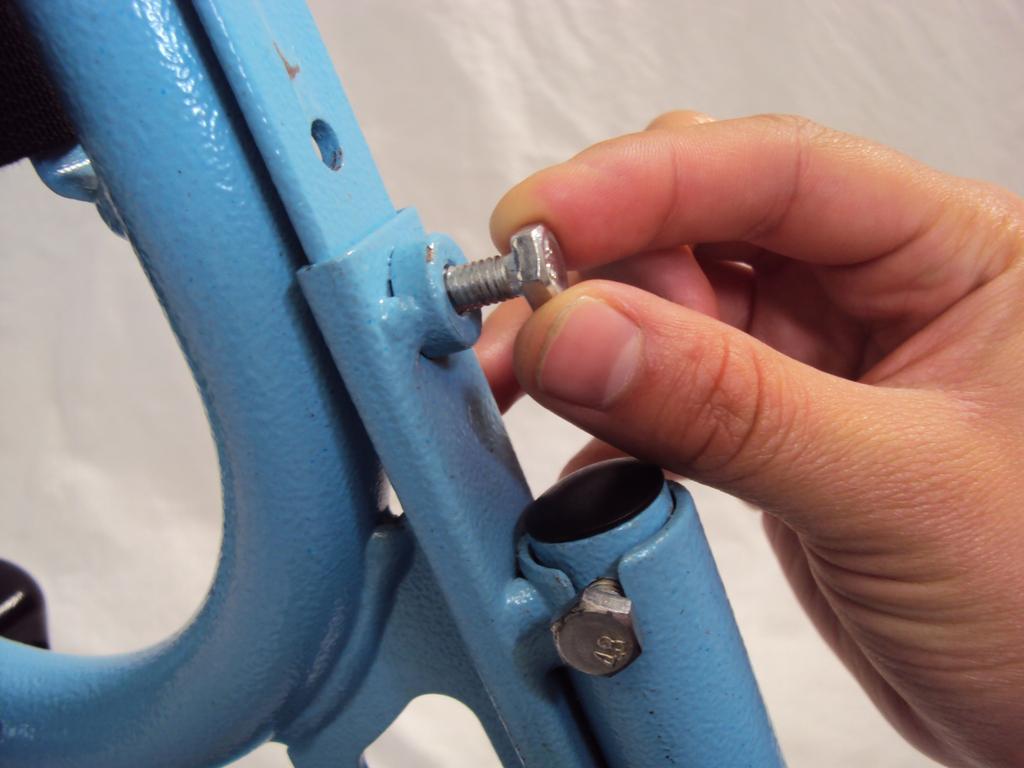
5 Step 5 Slide another ring shaped bearing piece into the castor hole on the frame. Insert the entire castor piece (castor, ring, and tube) into the opposite side of the hole. Secure the castor and bearing pieces with a castor bolt. Repeat on the opposite side of the frame. Step 6 Insert an axle bolt through the center of a rear wheel. Insert the axle bolt with wheel into the axle hole on the frame. Tighten the axle bolt. Secure the wheel with a bolt on the opposite side of the hole. Repeat on the opposite side of the frame to attach the other wheel. ifixit CC BY-NC-SA Page 5 of 10


6 Step 7 Slide each handle into the respective slot on the top of the wheelchair. Adjust the handles up or down to your desired height. Secure the handles in place with one bolt and nut for each side. Step 8 Insert the remaining crossbar between the handles, and align the holes on both sides. Secure the crossbar with four [4] blue tipped bolts and rubber tipped nuts (two on each side). ifixit CC BY-NC-SA Page 6 of 10


7 Step 9 Orient the plastic seat with the smooth side up. The rear strap can be attached to the seat in one of three positions in order to accommodate for people of different heights. Loop the straps over the bars of the frame on either side. Rotate the wheelchair onto its back side. Secure the seat by tying each strap together. Make sure that the straps are tied tightly so that the seat does not fall off the wheelchair. ifixit CC BY-NC-SA Page 7 of 10


8 Step 10 Reorient the chair so it is upright. Place the seat cushion on top of the plastic seat with the angled side in front. Step 11 Place the bottom of the backrest against the back of the seat cushion. Loop each strap behind the vertical bars of the frame. Secure the backrest by tying each strap together. Make sure that the straps are tied tightly so that the backrest does not fall off the wheelchair. ifixit CC BY-NC-SA Page 8 of 10


9 Step 12 Slide a footrest socket over the rail located near the front of the seat. Insert a footrest through the bottom of the footrest socket. Secure the footrest with a bolt above and below the socket. Adjust the footrest socket to your desired height. Align the socket's bolt with the nearest hole in the rail, and tighten the bolt. Repeat this step on the opposite rail. Step 13 Adjust the footrest socket to your desired height. Align the socket's bolt with the nearest hole in the rail, and tighten the bolt. Repeat this step on the opposite rail. ifixit CC BY-NC-SA Page 9 of 10

10 Step 14 Insert the pump bracket through the lower crossbar. Secure the bracket with a rubber tipped nut. Place the tire pump in the bracket. To disasemble your device, follow these instructions in reverse order. This document was last generated on :21:38 AM. ifixit CC BY-NC-SA Page 10 of 10
MAG-CONV Basic, 48, 48R & Midline Front Mount
 Parts Required: Tools Used: Mag Wheels Brakes Brake Rods Mounting Bracket Anti Tippers 7/16" Wrench Screw Driver Rubber Mallet 5/8 Wrench 5mm Allen Wrench Step Execution Figures 1 Remove front 5" total
TRAILMATE METEOR ASSEMBLY MANUAL
 TRAILMATE METEOR ASSEMBLY MANUAL The Trailmate Meteor recumbent has been designed for easy assembly. This means more time to enjoy the smooth ride with single speed, 3 speed coaster brake and 21 speed
RIPPER PEDAL. Bearing / Axle Replacement. ( Disassembly )
") RIPPER PEDAL Bearing / Axle Replacement ( Disassembly ) 1 1. Use good quality tools to avoid stripping screw sockets. 2. When servicing your pedals, work on one side at a time to prevent parts from mixing
RIPPER PEDAL Bearing / Axle Replacement ( Disassembly ) 1 1. Use good quality tools to avoid stripping screw sockets. 2. When servicing your pedals, work on one side at a time to prevent parts from mixing
Assembly Instructions: AM-10 Hand & Foot Cycle Early Intervention Part #: 50-HFC-0105
 Assembly Instructions: AM-10 Hand & Foot Cycle Early Intervention Part #: 50-HFC-0105 Refer to the following instructions on how to assemble your tryke. Study the instructions carefully before beginning
Calf-Tel Pen System Assembly Instructions
 Calf-Tel Pen System Assembly Instructions (Instructions work for 4, 6, and the 7 Pen Systems) 1 ASSEMBLY OF PEN FRONT AND WALLS START THE ASSEMBLY BY LINING UP THE TWO UNI-DIRECTIONAL ARROWS IN THE TOP,
BY ALIEN TECHNOLOGIES CORP
 BY ALIEN TECHNOLOGIES CORP Assembly Instructions TopLift Pros YOU MAY ALSO REVIEW OUR ASSEMBLY VIDEO, PLAY AND PAUSE AT YOUR CONVENIENCE. JUST VISIT US AT WWW.TOPLIFTPROS.COM AND GO TO Customer Support
K1098 Priceless Salon Styling Chair
 K1098 Priceless Salon Styling Chair Keller International, LLC. 1-800-572-8772 1 Part # Part Name Picture Pieces 1 Armrests 1 left and 1 right 2 Backrest 1 3 Seat 1 4 Footrest 1 5 Pump Bail 1 6 G2 Pump
User Instructions Multiline Otter Scoreboard Caddy Assembly
 List of parts: User Instructions Multiline Otter Scoreboard Caddy Assembly Single Caddy Double Caddy 1 1 Base assembly with attached wheels 2 4 1 1 2 4 4 8 10 20 12 Uprights (60 or 74 aluminum extrusion)
Mini Cooper Lock Actuator
 2001-2006 Mini Cooper Lock Actuator Replacement This guide is on how to remove the lock actuator from the cars door. Written By: Jem ifixit CC BY-NC-SA www.ifixit.com Page 1 of 13 INTRODUCTION In order
Boat Lift Canopy Frame Assembly Instructions
 Patriot Docks Boat Lift Canopy Frame Assembly Instructions Helpful Tips: Assembling and installing the canopy frame and cover is a two person job. Additional help makes installation easier and is recommended.
SINCE 1922 P UBLICATION N O
 SINCE 1922 GARED SPORTS MICRO-Z SET-UP INSTRUCTIONS VERY IMPORTANT! READ INSTRUCTIONS CAREFULLY AND FOLLOW STEP BY STEP SET-UP PROCEDURE P UBLICATION N O. 5 5 1 7 5 2 9 1 6 Recommended tools and accessories.
ASSEMBLY OF THE KNOCKED-DOWN LADDERS: 8 to 12 STEPS STANDARD TOP AND SAFELOCK REQUIRED TOOLS
 ASSEMBLY OF THE KNOCKED-DOWN LADDERS: 8 to 12 STEPS STANDARD TOP AND SAFELOCK REQUIRED TOOLS SAFETY GLASSES 7/16" WRENCH OR SOCKET STEP LADDER OF APPROPRIATE HEIGHT (2) 9/16" WRENCHES OR SOCKETS RUBBER
Move System Swivel Caster Installation ( )
") Move System Swivel Caster Installation (002-10265-00) Caution Always disconnect power to chair before removing covers or performing any service procedures. Step 1: Remove Top Cover A) Position chair to
Move System Swivel Caster Installation (002-10265-00) Caution Always disconnect power to chair before removing covers or performing any service procedures. Step 1: Remove Top Cover A) Position chair to
Dublin Stalls Installation Instructions
 Dublin Stalls Installation Instructions RAMM Horse Fencing and Stalls 13150 Airport Hwy. Swanton, OH 43558-9615 1-800-434-8456 Rev. 9/13/17 Part Identification Round Track Bracket (4) (Not Painted) Round
Art Rack Assembly Instructions:
 Art Rack Assembly Instructions: ** PIECES ARE POWDER COATED Do not lay pieces on top of each other or on a hard, rough surface if possible. All bolts will pass from outside towards inside of the cage.
MODULAR BUMPER INSTALLATION MANUAL
 MODULAR BUMPER INSTALLATION MANUAL Parts List* 1 Center section 1 Side extension, passenger / right 1 Side extension, driver / left 1 Side cap, passenger / right 1 Side cap, driver / left 1 Brush guard,
Usage and Assembly Instructions
 Instructions #1037447 Product #795234 Revision D Usage and Assembly Instructions Rear Fork (Buttstock) Rear Fork Lock Knob Rail Lock Knob Front Fork (Forend) Rails Tilt Friction Knob Rail Extension Locks
Adjusting 45 Compass Hardware Including 4-Point
 Adjusting 45 Compass Hardware Including 4-Point Compass Hardware - US Patent No. 7,104,610 & 7,891,739 Apparatus for Mounting a Wheelchair Back Quick Release Fixed 4-Point The information in this manual
Written By: Brittany McCrigler
 Installing a Plastic Snap Using a Hand Press This guide shows you how to replace a plastic snap using a hand press Written By: Brittany McCrigler ifixit CC BY-NC-SA www.ifixit.com Page 1 of 13 INTRODUCTION
TROLLA LEAVY 97 CM Lawn sweeper
 TROLLA LEAVY 97 CM Lawn sweeper Artikel nr.: 1008 EN Operating manual 014/1 Dear Customer, Congratulations on your new Trolla product. We hope you will enjoy it. Checkout with your new Trolla product may
08+ KAWASAKI KLR PD NERF
 08+ KAWASAKI KLR PD NERF 0505-1299 Before you begin, place the bike on a hard level surface where you have room to work. Lay out the parts included in this kit and compare to the parts list on page 5 of
CTTR Tire Rack Required tools
 CTTR Tire Rack Required tools Torque wrench, ratchet, 9/16 socket, tape measure, and square edge. ASSEMBLY REQUIREMENTS *Torque all T-bolt nuts to 35-40 foot pounds. Failure to follow the assembly instructions
For additional assistance call
 The following pages will help guide you through the process of assembling your new 48 custom prize wheel. Choose an assembly area with plenty of room to lay your pieces on the floor and also a bench or
AX1001. Smith/Functional training Combo-free weight ASSEMBLY INSTRUCTIONS
 AX1001 Smith/Functional training Combo-free weight ASSEMBLY INSTRUCTIONS EXPLODED DIAGRAM 83 84 84 85/86 87 87 88 89 90 91 62 64 64 64 64 64 64 65 65 65 65 66 66 65 66 66 65 63 63 66 67 68 55 66 66 70
Footprint Mobile Assembly Instructions
 Footprint Mobile Assembly Instructions 1998754 Revision -1 Complete Series Master Packet If you have any questions concerning these instructions, please call Kimball Office Customer Service. 20 Kimball
Free Standing Frame and Canopy
 Patriot Docks Free Standing Frame and Canopy Required Tools: Cordless Drill, 3/8 drill bit, 17mm wrench, 18mm wrench, 6mm hex key (included), 8mm hex key (included) Helpful Tips: Assembling and installing
Product Information. Brass & Cast Bedsteads
 Product Information Brass & Cast Bedsteads parts CheCk list 4 0,4 6,5 0,6 0 slatted FraMe 01 headend 1 02 Footend 1 03 head end extension legs 2 04 side rails 2 05 end cross bar 2 06 Center cross bar 1
MODEL T28173/T28174 ROLLER TABLES INSTRUCTIONS
 MODEL T28173/T28174 ROLLER TABLES INSTRUCTIONS FOR MODELS MFD. SINCE 10/17 For questions or help with this product contact Tech Support at (570) 546-9663 or techsupport@grizzly.com Rails Rollers Reversible
STELLA AUTO SIDECAR INSTALL INSTRUCTIONS
 STELLA AUTO SIDECAR INSTALL INSTRUCTIONS Open crate and inspect sidecar Remove cardboard box from inside the sidecar Remove all hardware holding the sidecar to the crate Remove sidecar from crate Remove
Black and Decker CD2500 Motor Replacement
 Black and Decker CD2500 Motor Replacement The guide shows you how to replace the motor in a Black and Decker CD2500. Written By: Ashley ifixit CC BY-NC-SA www.ifixit.com Page 1 of 9 INTRODUCTION Make sure
Q-Zone Hoop-Frame. Assembly Instructions. Copyright July 11, 2018 Grace Company (Reproduction Prohibited) Version 1.8
 Version 1.8") Q-Zone Hoop-Frame Assembly Instructions Copyright July 11, 2018 Grace Company (Reproduction Prohibited) Version 1.8 Table of Contents Table of Contents... i Warranty... ii Parts List Box 1...iii Box 2...
Q-Zone Hoop-Frame Assembly Instructions Copyright July 11, 2018 Grace Company (Reproduction Prohibited) Version 1.8 Table of Contents Table of Contents... i Warranty... ii Parts List Box 1...iii Box 2...
43107 Rhino Jerry Can Holder Rhino Jerry Can Holder - Horizontal
 Important: Please read these instructions carefully prior to installation. Check the contents of kit before commencing fitment and report any discrepancies. Clean the alloy tray prior to installation.
BLADE N BULLET BLIND Cabela s Item Number:
 BLADE N BULLET BLIND Cabela s Item Number: 466353 Visit cabelas.com or call 1-800-237-4444 for assistance. TABLE OF CONTENTS 2 3 4-13 Table of Contents Package Contents Instructions for Use Visit cabelas.com
RedRock 4x4 Rock Crawler Rear Bumper w/tire Carrier - Textured Black (87-06 Wrangler YJ & TJ)
") RedRock 4x4 Rock Crawler Rear Bumper w/tire Carrier - Textured Black (87-06 Wrangler YJ & TJ) Installation Time: 3+ Hours Tools Required: Ratchet 18 mm Socket and Wrench 17 mm Socket and Wrench 16 mm Socket
RedRock 4x4 Rock Crawler Rear Bumper w/tire Carrier - Textured Black (87-06 Wrangler YJ & TJ) Installation Time: 3+ Hours Tools Required: Ratchet 18 mm Socket and Wrench 17 mm Socket and Wrench 16 mm Socket
ABM International, Inc. Navigator Assembly Manual
 ABM International, Inc. 1 1.0: Parts List Tablet (Qty. 1) Tablet mount (Qty. 1) NOTE: Mount may appear and operate different then image below Control Box (Qty. 1) Motor Power Supply (Qty. 1) 2 X-axis motor
ORTOP Modular Robot v3.0 Arm Assembly
 Base Plate Assembly Parts Needed: Arm Assembly BAG 1 2 Socket Head Cap Screw, 1-1/4" 2 Socket Head Cap Screw, 1/2" 2 Button Head Cap Screw, 3/8" 6 Nuts 1 Gear Hub Spacer 1 Flat Building Plate 1 Single
Medium HoneyBadger Chase Rack Installation Instructions
 PREPARATION Medium HoneyBadger Chase Rack Installation Instructions 1. Disconnect the negative terminal on the battery. Park the vehicle on level ground and set the emergency brake. 2. We recommend reading
Replacing the Reciprocator on the SWF Compact Series Machine (601C and 1201C)
") Follow the instructions below to replace the reciprocator in the SWF Compact series machines. The tools required can be found in the tool kit that came with the machine. Preparation 1. First, place the
Follow the instructions below to replace the reciprocator in the SWF Compact series machines. The tools required can be found in the tool kit that came with the machine. Preparation 1. First, place the
TOOLS REQUIRED FOR ASSEMBLY. Rubber Mallet or Plastic Tip Hammer PARTS REQUIRED FOR ASSEMBLY OF SINGLE ENTRY STARTER.
 TOOLS REQUIRED FOR ASSEMBLY Rubber Mallet or Plastic Tip Hammer Top Cover Support PARTS REQUIRED FOR ASSEMBLY OF SINGLE ENTRY STARTER Back Stop Divider Closed 'L' Upright Slotted Reinforcement Support
WARNING: THERE IS ALWAYS A DANGER OF INJURY WHEN
 Assembly Instructions: AM 10 Hand & Foot Cycle Early Intervention Part #: 50 HFC 0105 Refer to the following instructions on how to assemble your tryke. Study the instructions carefully before beginning
Continuum Frame Assembly Instructions
 Continuum Frame Assembly Instructions Copyright January 1, 2017 Jim M. Bagley, GraceWood, Inc (Reproduction Prohibited) Version 2.2 Table of Contents Continuum Frame Table of Contents... i Warranty...ii
RH-412 STEEL DOORS INSTALLATION INSTRUCTIONS
 RH-412 STEEL DOORS INSTALLATION INSTRUCTIONS By following the steps outlined below, the assembly, installation and adjustment of the steel doors, will be a simple process. Let s start with the Driver Side.
S48-L12-SC AND G48-L12-GC STEEL PORTA-DOCK S82 SC 6 X 12 PLATFORM AND G82 GC 6 X 12 PLATFORM
 PAGE 1 OF 6 PORTA-DOCK, INC. S48-L12-SC AND G48-L12-GC STEEL PORTA-DOCK S82 SC 6 X 12 PLATFORM AND G82 GC 6 X 12 PLATFORM Thank you for purchasing our product! *Please read these instructions and follow
Signature Choral Riser Side Rail
 Assembly/Owner s Manual Signature Choral Riser Side Rail Signature Choral 3-Step Riser with Optional Side Rail Signature Choral 4-Step Riser with Optional Side Rail CONTENTS Visit the Signature Choral
Assembly Instructions Eggstreme Chicken Coops
 Assembly Instructions Eggstreme Chicken Coops Tools Needed Drill/Driver #2 screwdriver bit Pliers Scissors or wire cutter 3/4 wrench Parts List PO Box 1340 Henderson, TX 75653 800-527-1459 To insure a
Mac mini Model A1283 Speaker Replacement
 Mac mini Model A1283 Speaker Replacement Written By: Walter Galan ifixit CC BY-NC-SA www.ifixit.com Page 1 of 14 INTRODUCTION Restore sound to your mini by replacing the speaker. TOOLS: Jimmy (1) Phillips
IN 578. Tools Required. Torque Specification: 10mm Socket 7/16 Socket 1/2 Socket 1/2 Wrench 7/16 Wrench 1/8 Allen Wrench.
 Tools Required 2011-C Ford F250/F350 No Drilling into Vehicle is Required 10mm Socket 7/16 Socket 1/2 Socket 1/2 Wrench 7/16 Wrench 1/8 Allen Wrench FL277 x 1 Torque Specification: 1/4 Bolts - 6 Ft Lbs.
INSTALLATION INSTRUCTIONS RH 412 STEEL DOORS
 By following the steps outlined below, the assembly, installation and adjustment of the steel doors, will be a simple process. Let s start with the Driver Side. Note: Having the hood open makes the job
17MAY18 U.S. RACK, Inc Falcon Drive, Madera, CA
 17MAY18 U.S. RACK, Inc. - 2850 Falcon Drive, Madera, CA 93637-559-661-3050 INSTRUCTIONS for FIFTH WHEEL RACK Model 2010-4AD WARNING: Do NOT attempt to install or use this rack without following all instructions.
Usage and Assembly Instructions
 Instructions #1037447 Product #795234 Revision C Usage and Assembly Instructions Rear Fork (Buttstock) Rear Fork Lock Knob Rail Lock Knob Front Fork (Forend) Rails Tilt Friction Knob Rail Extension Locks
SAVVY OFF ROAD GAS TANK SKID INSTALLATION INSTRUCTIONS
 It is best to work with a fuel tank that has the least amount of fuel in it as possible. Thank you for purchasing the best skid on the market. Please follow these instructions and your installation should
1. Remove factory stock bump stop and mount from the frame.
 1. Disconnect the negative terminal on the battery. With the vehicle on level ground and the emergency brake set, block the front tires. 2. Jack up the rear of the vehicle and support the frame rails with
Important Loading Information. Tools Required. Meridian Lateral Files Instructions
 Y Meridian Lateral Files Instructions! WARNING Failure to observe stated capacities below will result in unsafe usage conditions, causing possible product damage or personal injury. Important Loading Information
TIRE RACK INSTALLATION INSTRUCTIONS Dodge Sprinter
 Aluminess Products Inc 9402 Wheatlands Ct. #A Santee, CA 92071 619-449-9930 TIRE RACK INSTALLATION INSTRUCTIONS 07-11 Dodge Sprinter Please read before beginning Stainless steel hardware may bind together
Pickup Box Utility Rack Package Installation (Instruction ID: )
") 017 Chevrolet Colorado Pickup - WD (VIN S) Canyon, Colorado Accessory Installation Manual N America Document ID: 3966961 Pickup Box Utility Rack Package Installation (Instruction ID:3144879) Installation
017 Chevrolet Colorado Pickup - WD (VIN S) Canyon, Colorado Accessory Installation Manual N America Document ID: 3966961 Pickup Box Utility Rack Package Installation (Instruction ID:3144879) Installation
ASSEMBLY & INSTALLATION GUIDE
 ASSEMBLY & INSTALLATION GUIDE APPLICATION GM Truck (Full-size Trucks) PART # 74805-00A (Silver) 74805-0A(Black) INSTALLATION TIME Hour SKILL LEVEL 2 3 4 = Easy TOOLS REQUIRED Phillips screw driver Torx
This instruction manual is an in-depth look and explanation of how to assemble and install the Murphy Bed properly and efficiently.
 This instruction manual is an in-depth look and explanation of how to assemble and install the Murphy Bed properly and efficiently. Don t be put off by the size of the instruction manual as the large diagrams
The Festival Assembly Instructions
 The Festival Assembly Instructions Toll Free: 866.768.8465 Hours: 9-5 Monday-Friday EST www.homeplacestructures.com Package ships as shown CONTACT INFORMATION: HomePlace Structures 301 Commerce Drive New
Apple Wireless Keyboard (A1255) Teardown. Written By: mayer. ifixit CC BY-NC-SA Page 1 of 11
 Teardown. Written By: mayer. ifixit CC BY-NC-SA Page 1 of 11") Apple Wireless Keyboard (A1255) Teardown Written By: mayer ifixit CC BY-NC-SA www.ifixit.com Page 1 of 11 INTRODUCTION I bought this keyboard off ebay broken just to tear it down for posterity. I found
Apple Wireless Keyboard (A1255) Teardown Written By: mayer ifixit CC BY-NC-SA www.ifixit.com Page 1 of 11 INTRODUCTION I bought this keyboard off ebay broken just to tear it down for posterity. I found
Jenny Legs Assembly Instructions
 Jenny Legs Assembly Instructions R EXTENDED PHILLIPS BIT MM ALLEN WRENCH 6MM HEX DRIVE /" 007 Steelcase Inc. Grand Rapids, MI 90 U.S.A. Printed in U.S.A. Page of 6 88000 Rev F Jenny Club Instructions:
MANUAL DE MONTAJE ASSEMBLY MANUAL AIREADOR DE PLUG AERATOR MODEL # AE-48T. Hardware & Parts Listing Assembly Instructions Maintenance Notes for
 ASSEMBLY MANUAL Hardware & Parts Listing Assembly Instructions Maintenance Notes for 48 PLUG AERATOR MANUAL DE MONTAJE Lista de piezas y tornillería Instrucciones de armado Notas de mantenimiento para
Installation for Full Size Polaris Ranger Crew Doors
 Installation for Full Size Polaris Ranger Crew Doors Order of Installation: Heater Doors Wiper on to Windshield Windshield Top & Back Panel Note: Most of the steps in these instructions need to be repeated
STEP 1 STEP 2 LEVELER KIT OPTION MOBILE CASTER KIT OPTION
 B SERIES INDUSTRIAL BENCHES TOOLS REQUIRED FOR ASSEMBLY Socket set, Open end wrench set, Cordless drill with 3/8" socket bit (Magnetic recommended). BEFORE ASSEMBLY Read through the assembly instructions
27APR18 U.S. RACK, Inc Falcon Drive, Madera, CA
 27APR18 U.S. RACK, Inc. - 2850 Falcon Drive, Madera, CA 93637-559-661-3050 INSTRUCTIONS for FIFTH WHEEL RACK Model 2010-4ADC WARNING: Do NOT attempt to install or use this rack without following all instructions.
Written By: Walter Galan
 iphone 4S Logic Board Replacement Replace a dead logic board in your iphone 4S. Written By: Walter Galan ifixit CC BY-NC-SA www.ifixit.com Page 1 of 22 INTRODUCTION Use this guide to replace your iphone's
FlexFrame - Storage Components and Skins
 FlexFrame - Storage Components and Skins 1/4 Square Drive Ball-Point Hex-Bit Socket 1/8 Short Hex, 1-1/2 Overall Length McMaster Part # 54075A44 Table of Contents Topic Page Storage Components 2 General
Nikon Coolpix E5700 Top Cover Replacement
 Nikon Coolpix E5700 Top Cover Replacement Removing the top cover of the camera. Written By: Kyle Sitton ifixit CC BY-NC-SA www.ifixit.com Page 1 of 12 INTRODUCTION This guide will walk you through the
INS T A L L A TIO N INS T R U C TIO N S. Ceiling Mount Track System
 Ceiling Mount Track System 10.26.2016 Specifications Ceiling Post: Unassembled 2-7/8 Assembled 1-11/16 7/8 7-9/16 5-7/8 3/8 2 Tubes 1/2 2-3/8 5 Parts and Tools Tools Needed Tape Measure Pencil Drill with
Instruction Guide 4A90L
 Instruction Guide 4A90L Kargo Master Rancho Cordova, CA 95742 800-343-7486 CustomerService@KargoMaster.com DATE: *PLEASE READ ALL INSTRUCTIONS AND WARNINGS PRIOR TO ASSEMBLING, INSTALLING, AND USING THIS
!ATTENTION: READ BEFORE ASSEMBLING/OPERATING! ASSEMBLY & PACKING INSTRUCTIONS FOR THE MULTICHAIR 6000 Series
 !ATTENTION: READ BEFORE ASSEMBLING/OPERATING! ASSEMBLY & PACKING INSTRUCTIONS FOR THE MULTICHAIR 6000 Series multichair 6000 multichair 6200!ATTENTION: READ BEFORE ASSEMBLING/OPERATING! November 2016 ASSEMBLY
Special Z-Axis Ballscrew Replacement
 To replace Z-axis ballscrew without removing X-axis components When rebuilding an OmniTurn slide, all the precision components are replaced. The tooling plate and saddle are removed to gain access to the
Adjusting 90 Compass Hardware Including 4-Point
 Toll Free 800.564.948 www.comfortcompany.com 509 South nd Ave Bozeman, MT 59718 Adjusting 90 Compass Hardware Including 4-Point Compass Hardware - US Patent No. 7,104,610 & 7,891,739 Apparatus for Mounting
GlideRite Retractable Cover System For HotSpring & Tiger River Spas (except Classic & pre-2000 Landmark Spas)
") List of Contents Quantity Description 12 #10 x 1 ½ Flat Head Phillips Screw (see pg. 2) 2 #10 x ½ Pan Head Phillips Screw (see pg. 2) 8 ¼ x 2 ½ Lag Bolt (see pg. 2) 7 ¼ 20 x 5 / 8 Hex Head Bolt (see pg.
List of Contents Quantity Description 12 #10 x 1 ½ Flat Head Phillips Screw (see pg. 2) 2 #10 x ½ Pan Head Phillips Screw (see pg. 2) 8 ¼ x 2 ½ Lag Bolt (see pg. 2) 7 ¼ 20 x 5 / 8 Hex Head Bolt (see pg.
-1- J K L (X2) (X3)
 (X3)") www.smartrike.com 680 LOOK US UP ON YOUTUBE: www.youtube.com/user/smarttrikeofficial Thank you for buying smartrike, If you have any assembly issues or are missing a part, please call us for assistance.
www.smartrike.com 680 LOOK US UP ON YOUTUBE: www.youtube.com/user/smarttrikeofficial Thank you for buying smartrike, If you have any assembly issues or are missing a part, please call us for assistance.
Hardware and Components:
 Hardware and Components: (A) 5/16 x 2 Hex Bolt (B) 5/16 x 2-1/4 Hex Bolt (C) 5/16 x 2-1/2 Hex Bolt (D) 4X 5/16 x 3/4 Hex Bolt (E) 4X 5/16 x 1-1/4 Hex Bolt (F) 11X 5/16 Flat Washer (G) 12X 5/16 Nylock Nut
Xbox 360 Eject Button Replacement
 Xbox 360 Eject Button Replacement Eject button replacement. Written By: Walter Galan ifixit CC BY-NC-SA www.ifixit.com Page 1 of 17 INTRODUCTION This guide will help you replace a damaged or broken eject
KAWASAKI KLRE PD NERF HTP4-8-5 & HIGHWAY PEGS HTP4-1-4B
 Thank you for purchasing Happy Trails products. Our products are proudly hand made in Boise Idaho, USA. If you have any questions or concerns about the installation of this product, please contact us directly
Versa Shower/Commode Transfer System Instructions
 Versa Shower/Commode Transfer System Instructions Model #5100 Thank you for Choosing Columbia Your Columbia Versa Shower/Commode/Bath Transfer System has been built to the highest standards of quality
HQ Pole Upgrade Kit for HQ Adjustable Table and HQ QuilTable Assembly Instructions 1
 HQ Pole Upgrade Kit for HQ Adjustable Table and HQ QuilTable Assembly Instructions QF09775 The pole upgrade kit can be used with or without the QF09700 HQ Precison-Glide track upgrade kit. What s Included
F l a t S c r e e n A R M S I n s t a l l a t i o n
 ITEM NUMBERS (1) #TOACAORG16 (2) #TOACAORG20 (3) #TOACATRP24 (4) #TOACATRP30 (5) #TOACATRPDS (6) #TOACATRPSS TOOLS REQUIRED (1) 3/8 Wrench (not provided) (2) Phillips head screwdriver (not provided) (1)
US RACK, Inc Falcon Drive, Madera, CA
 US RACK, Inc. - 2850 Falcon Drive, Madera, CA 93637-559-661-3050 INSTRUCTIONS for MOTORCYCLE RACK with Cradling Wheel Chocks WARNING: Do NOT attempt to install or use this rack without following all instructions.
Rugged Ridge 2 Receiver Hitch Kit (J21068)
") Rugged Ridge 2 Receiver Hitch Kit (J21068) Installation Time: 1-2 Hours Tools Required: ¾ Open End Wrench 18 mm Socket ¼ drive Pliers/Needle nose pliers/channel locks, etc. Torque wrench Phillips head
Rugged Ridge 2 Receiver Hitch Kit (J21068) Installation Time: 1-2 Hours Tools Required: ¾ Open End Wrench 18 mm Socket ¼ drive Pliers/Needle nose pliers/channel locks, etc. Torque wrench Phillips head
PPFE 12 Miter Disk Sander
 PPFE 12 Miter Disk Sander Instructional Manual 1 2017 framingsupplies.com Parts 1. Base 2. Sanding Wheel 3. Guide 4. Guide Axle 5. Guide Handle 6. Bearing Assembly 7. Triangle 2 3 6 7 4 1 5 Set-Up Instructions
MOR/ryde Steer Axle Suspension System
 MOR/ryde Steer Axle Suspension System (Double Eye Leaf Spring) Steer Axle Installation Instructions MOR/ryde International 1966 Moyer Avenue Elkhart, IN 46516 574-293-1581 www.morryde.com SRL153-001 REV.
INSTALLATION GUIDE 2009-CURRENT HUMMER H3T PRODUCT CODE:
 INSTALLATION GUIDE 2009-CURRENT HUMMER H3T PRODUCT CODE: 268 June 22, 2010 TOOLS NEEDED COMPONENTS INCLUDED P2 Tip 3/8" Drill Rubber Gasket(s) x 2 Bracket(s) x 2 1/2" Drill Bit Bulkhead Flange #2 Phillips
General Guidelines:
 ASSEMBLY INSTRUCTIONS Congratulations on your new Patriot Dock purchase. This manual contains instructions to assemble basic dock configurations for use at typical residential shoreline application. Please
Written By: Walter Galan
 Xbox 360 CPU Heat Sink Replacement CPU heat sink replacement. Written By: Walter Galan ifixit CC BY-NC-SA www.ifixit.com Page 1 of 27 INTRODUCTION Use this guide to remove the CPU heat sink from your Xbox
OWNERS MANUAL MODEL F660 HIP SLED
 OWNERS MANUAL MODEL F HIP SLED QUESTION? As a quality home gym supplier we are committed to your complete satisfaction. If you have questions, or find missing or damaged parts, we will guarantee your complete
USSC LLC 4 ONE LLC FIELD MODIFICATION INSTRUCTIONS
 1 OF 17 A 1. PURPOSE: Instructions for in field replacement of 9004 mechanical suspension top pan 2. SCOPE: 9004 mechanical suspension with legacy two point LX back frame and current LX back frame 3. PROCEDURE:
TABLE OF CONTENTS REQUIRED TOOLS
 TABLE OF CONTENTS SECTION SECTION TITLE PAGE NO. 1 2 3 4 5 Assembling Mounting Structure Installing Bicycle Supports Mounting Rack to Wall Adding Sections Customizing Rack Configuration REQUIRED TOOLS
!ATTENTION: READ BEFORE ASSEMBLING/OPERATING! ASSEMBLY INSTRUCTIONS FOR THE MULTICHAIR 6000Tilt Series
 !ATTENTION: READ BEFORE ASSEMBLING/OPERATING! ASSEMBLY INSTRUCTIONS FOR THE MULTICHAIR 6000Tilt Series multichair 6000Tilt multichair 6200Tilt multichair 6000Tilt P1 multichair 6000Tilt P2!ATTENTION: READ
INSTRUCTION MANUAL MANUAL DE INSTRUCCIONES
 INSTRUCTION MANUAL MANUAL DE INSTRUCCIONES Model Number/ No. de Modelo: WDB101 CLOTHES DRYER STACKING BRACKET CAUTION: BEFORE USE, PLEASE READ AND FOLLOW ALL SAFETY RULES AND OPERATING INSTRUCTIONS. Avanti
Monaco Installation Guide - Surface Profiles
 v1 Page 1 Thank you for purchasing this Monaco shower screen. Please study these instructions carefully before assembly and installation and check all supplied parts immediately upon receipt. These instructions
BARN DOOR HARDWARE KIT
 INSTALLATION GUIDE Main Components x1 Rail x5 Wall Spacer x2 Anti-jump Block x2 Bent Strap x1 Right Stopper x1 Left Stopper x5 5/16 (8mm x 60mm) Carriage Bolt x5 5/16 (8mm x25mm) Anchor x5 5/16 (8mm x
Installation Instructions Kit, Base Rail Bracket Part # 31413
 Installation Instructions Kit, Base Rail Bracket Part # 31413 Dealer / Installer: Provide a copy of these Instructions to the end user of this product. These Instructions provide important operating and
IDR assembly instructions:
 IDR assembly instructions: Required Tools: 2 X 12mm Open End Wrench 14mm open end wrench #2 Phillips Head Screw Driver (Drill with adjustable torque clutch recommended) 8mm nut driver (Supplied in IDR-AK)
Barricade Trail Force HD Rear Bumper w/ Tire Carrier installation (07-16 Wrangler JK)
") Barricade Trail Force HD Rear Bumper w/ Tire Carrier installation (07-16 Wrangler JK) Installation Time: 2-3 Hours Tools Required: Tire iron Ratcheting socket set (ratchet plus 13, 16, 19mm sockets) Open
Barricade Trail Force HD Rear Bumper w/ Tire Carrier installation (07-16 Wrangler JK) Installation Time: 2-3 Hours Tools Required: Tire iron Ratcheting socket set (ratchet plus 13, 16, 19mm sockets) Open
Tools: Sharpie, Square, Vise, Hack saw, Ruler, Punch, Hammer, File. 2. Cut the stock Place stock in vise and cut with hack saw
 Purpose: MAKE CATAPULT ARM Step 1 Tools: Sharpie, Square, Vise, Hack saw, Ruler, Punch, Hammer, File Materials: Flat aluminum ½ inch stock (see picture below) Gloves required 1. Pick up the aluminum ½
400A 40113V, 401A 40120V, & 401AL 40120VL ALUMINUM VERTICAL 4000 LB LIFT INCLUDES SCREW LEG ASSEMBLY INSTRUCTIONS
 12/11/07 PAGE 1 OF 12 400A 40113V, 401A 40120V, & 401AL 40120VL ALUMINUM VERTICAL 4000 LB LIFT INCLUDES SCREW LEG ASSEMBLY INSTRUCTIONS Thank you for purchasing our product! *Please read these instructions
Assembly Instructions 10 X 10 Aluminum Roof Support
 Assembly Instructions 10 X 10 Aluminum Roof Support Aluminum Roof Support Bolt Package 16-5/16 X 2 ¼ SS Bolt 24-5/16 X 1 SS Bolt 40-5/16 SS Nylon Lock Nuts 16-5/16 SS Flat Washers 28-4 ½ Wood Screws 36-1