SpeedCell Installation Instructions
|
|
|
- Oswald Leonard
- 6 years ago
- Views:
Transcription


1 SpeedCell Installation Instructions ***Installation typically requires two people***
 8(a) 8(b) 8(c) KEY 1.")

 4. 2 Ladders 5.")


2 Required Tools (3a) (a) 8(a) 8(b) 8(c) KEY 1. Philips Screw Driver 2. Crescent Wrench 3. 3/8 Socket Wrench a) 7/16 Socket (~11mm) 4. 2 Ladders 5. Measuring Tape 6. Permanent Marker 7. 3/8 Drill a) 3/8 (~10mm) Nut Driver 8. Optional Equipment: a) 5/16 (~8mm) Drill Bit b) Pipe Cutter c) Deburring Tool

 3. Nylon Spacer 4.")
, 1.5 x.")
,.25 x.")

3 List of Materials KEY 1. Bolt, 1.5 x.375 dia. (~38mm x 9mm) 2. Flat Washer,.25 (6mm) 3. Nylon Spacer 4. Nylon Lock Nut,.25 (6mm) 5. Tek Screw (Long), 1.5 x.25 (38mm x 6mm) 6. Tek Screw (Short),.25 x.25 dia. (6mm x 6mm) 7. Single Bracket 8. Crossbar 9. Suspension Track 10. Column
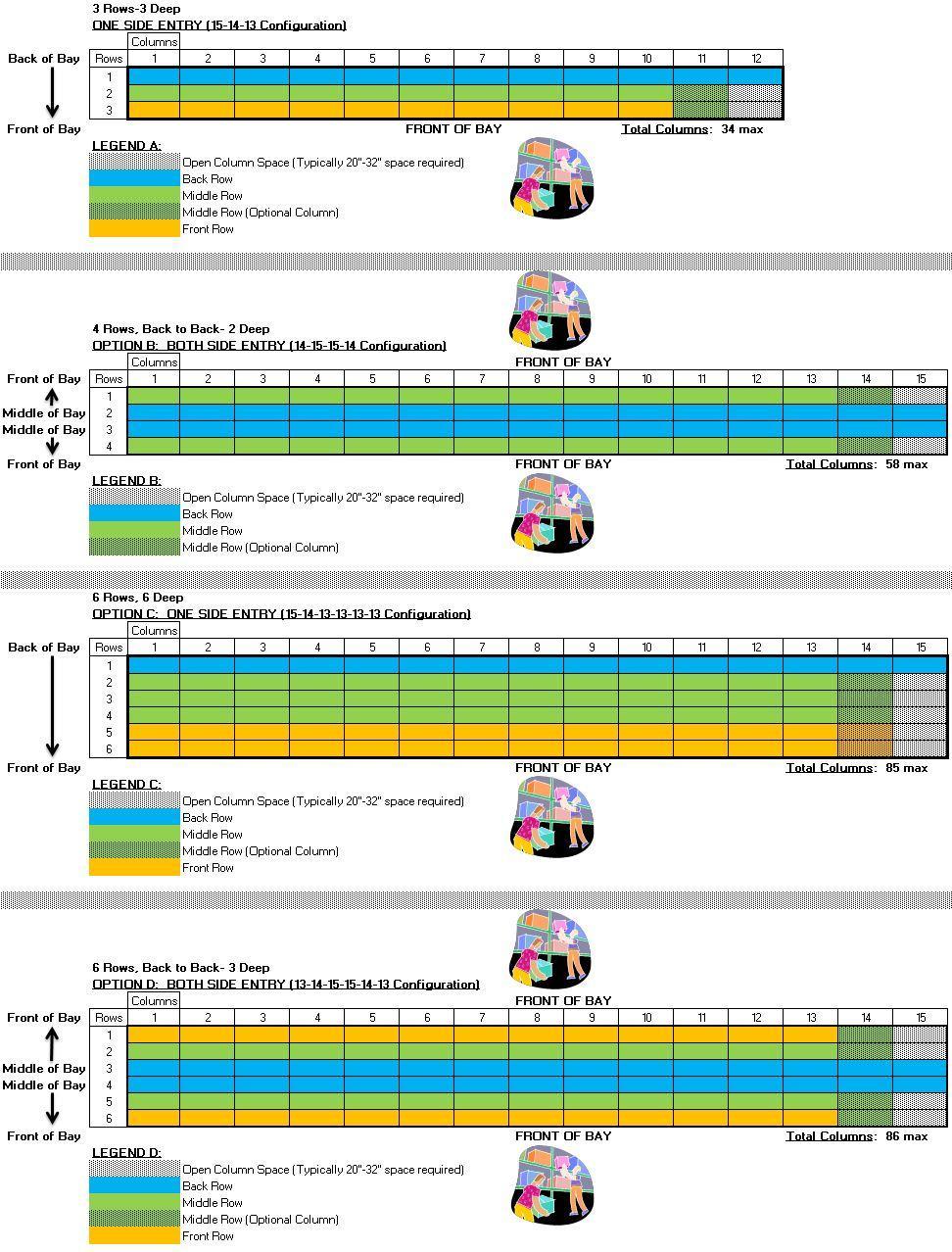
4 Bay Configuration Examples

 and place a mark or set a crossbar. b.")
5 Crossbar Installation 1. Start your SpeedCell installation off right by making sure your racking bay is square, plum, & level and that your beams are at the same elevation. 2. Properly locate the crossbars on your beams: a. Locate the center line of the beam, place a locating mark or set a crossbar between the beams. Note: 4 crossbar installations, will use the center line as a reference point. Measure out in both directions of the C/L 18 (457mm) and place a mark or set a crossbar. b. Locate the outer most crossbars, measure from the uprights measure inward on the beams 12 (305mm), place a locating mark or set a crossbar between the beams (do this for all installations). 3. Begin securing crossbars a) Starting with the back beam, loosely Tek Screw (Long) the back end crossbar to the beam (see NOTE below) ****(Do not secure the crossbar to the front beam at this time)**** NOTE: Only loosely tek screw each crossbar (~1/4 (6mm) a few threads deep) into the back beam at this time. The crossbar should be secure enough to prevent the crossbar from falling out of the beam, but not so tight that it will prohibit lifting the front end of the crossbar above the top edge of the front beam. This play is needed to allow you to put the brackets & tracks on the crossbars. 4. Install the additional crossbars in the same manner, final securing of the crossbars will happen after all track assemblies are installed. 2. (Simple layout view) 3. (Crossbar initial install detail)
6 Track Installation: Materials For track installation you will need: 1. Brackets (see table for quantity per track) a) Tek screws (Short) 2. Tracks a) Track Stoppers (2 per track) 1) Bolt, washer, nylon spacer, nylon lock nut 3. Wrench, Crescent &/or Socket with 7/16 Socket 4. Philips screw driver 5. 3/8 Drill a) 3/8 (10mm) Nut Driver (Tek Screws) b) 7/16 (11mm) Nut Driver (Stopper Assembly) Optional Equipment 1. 3/8 (10mm) Drill Bit 2. Pipe Cutter & Deburring Tool a) (for use with column axles if modification is needed) Beam Length (Imperial) Brackets per Track Beam Length (Metric) Brackets per Track <10 3 >10 - <12 4 >12 - <14 5 <~3.1m 3 >~3.1m- <~3.7m 4 >~3.7m - <~4.3m 5


.")
7 Track Installation: Bracket Assembly Bracket Set-up 1. All single brackets are to have crossbars ran through them and are to be contained inside of the beams. ****Do not place brackets outside of the beams.**** 1. Layout the tracks in pairs facing each other. 2. Assemble a wheel stop on one end of each track. The proper assembly order for wheel stops: Bolt (1.5,~38mm), Track, Washer, Nylon Spacer, and Nylon Lock Nut 3. Carefully slide the single brackets onto the tracks. The suspension tracks should under hang the crossbar opening on the bracket. Refer to the table on page 5 for the number of brackets per track needed for proper installation. NOTE: Make sure that all the single brackets are facing the same direction and that they are NOT covering the notches on the top of the tracks, doing so will ensure proper installation. 4. Assemble the wheel stops on the other end of the tracks after installing all the single (same assembly order as #2). 2 3 Top Crossbar Opening Single Bracket, Top Bottom Wheel Stop Single Bracket, Bottom
 Do this with 2 people by lifting the track assemblies over the beams and by putting the crossbars through the brackets.")

8 Track Installation 1. Install the track & bracket assemblies on the crossbars from the front of the bay. a) Do this with 2 people by lifting the track assemblies over the beams and by putting the crossbars through the brackets. NOTE: With the track assemblies flat under the crossbars and with the bracket openings facing up & out, lift the crossbars with the tracks above the beam. -Rotate the Bracket & Track assemblies at the same time as you slide the brackets up and out over the crossbars thus sliding the crossbars into the bracket openings. 2. Secure Crossbars to beams a) Once the Bracket & track assemblies are on the crossbars, fully secure the crossbars to the beams using provided tek screws (Long). 3. Properly locate/space Tracks on the crossbars a) Starting at back of the bay pull the bracket flush to the beam and tek screw (small) in place 3 NOTE: 1. Black line =Tracks 2. Red line=beams 3. Arrows=Track Direction 4. Numbers=Track Installation Order
9 Track Installation Continued 1. Proper Alignment & Spacing of Tracks: a) Work from the back of the bay to the front b) Use a pair of column axles to properly space out the tracks. c) Slide the middle row tracks into place making sure to leave a minimum of 1 of space between the rows. d) When properly spaced the track pairs will be parallel to the beams & allow the axles to roll smoothly. e) Before Tek Screwing the brackets into the Crossbar, make sure the brackets lay flat on the Crossbars. This will help prevent the brackets from lifting off the crossbar when securing them. f) Repeat this process of aligning, spacing, and securing the tracks until all rows of tracks are in place. 2. Once all the rows of tracks are aligned and spaced make sure all the brackets are Tek Screwed (Short) to the crossbar. 4. Proceed to Column Installation


10 Column Installation 1. Start installing columns in the back row. Use the notches in the track to slide the column axle into tracks. NOTE: Prior to suspending the columns make sure that the axles are through all four of the webbing loops. If not, remove one roller and slide the axle properly through the loop. Reinstall the roller and proceed with installation. 2. The back row is complete when there is no more room for columns or meets installation layout. It should have no open column spaces. 3. Make sure to Proceed to install the remaining rows using the same methods as in (1&2) but leave out, a minimum, 1 column space per row. 4. Make sure to install the columns in each row per provided design. The will ensure the bay is configured properly and will function. Yes No 2 NOTE: A typical three row deep installation will have a back row with no open column space and some number of columns less in the front two rows. Leaving these column spaces out in the middle and front rows allows you to gain access to the bay interior rows/columns by sliding the front row columns out of the way. A typical bay ideally is configured with the follow clearances: -walk space clearance of reach space clearance of 8-16 Typical Bay Configuration Rows # of Columns Row 1/Front 8 Row 2/Middle 8-9 Row 3/Back 10
SpeedCell Installation Instructions
 SpeedCell Installation Instructions ***Installation typically requires two people*** Required Tools 1 2 3 (3a) 5 6 7 7(a) 8(a) 8(b) 8(c) 1. Philips Screw Driver 2. Crescent Wrench 3. 3/8 Socket Wrench
TOOL LIST FOR TAILGATE HIDDEN LATCH & LINK ASSY FOR FORD FLARESIDE TRUCKS
 TOOL LIST FOR TAILGATE HIDDEN LATCH & LINK ASSY FOR 53-87 FORD FLARESIDE TRUCKS Vise Grip Clamps C-clamps Sharpie Marker Ball Peen Hammer Center Punch 3/8 or 1/2 Drill 5/32, 7/32, 9/32, and 3/8 Drill Bits
SmartView Mounting Frame 3 Wide x 3 Deep Video Wall Display Installation Guide
 SmartView Mounting Frame 3 Wide x 3 Deep Video Wall Display Installation Guide WMK-034 This display kit mounts ViewSonic 46 Video Wall displays in a 3 wide by 3 deep landscape configuration. The frame
GRILLE GUARD SPRINTER VAN (EXCLUDES X4) INCLUDES MERCEDES, FREIGHTLINER AND DODGE PARTS LIST:
 INCLUDES MERCEDES, FREIGHTLINER AND DODGE PARTS LIST:") PARTS LIST: 1 Grille Guard 8 12mm Hex Nuts 1 Driver/Left Side Frame Mounting Bracket 2 10-1.50mm x 25mm Button Head Bolts 1 Passenger/Right Side Frame Mounting Bracket 4 10mm x 20mm OD x 2mm Flat Washers
PARTS LIST: 1 Grille Guard 8 12mm Hex Nuts 1 Driver/Left Side Frame Mounting Bracket 2 10-1.50mm x 25mm Button Head Bolts 1 Passenger/Right Side Frame Mounting Bracket 4 10mm x 20mm OD x 2mm Flat Washers
Installation Instructions - Model V4JSD 1
 Installation Instructions - Model V4JSD 1 Support Assemblies: Parts list: (Note see enclosed cut sheet for quantities and dimensional information) A vertical structural member (1 ½ x 1 ½ modular frame)
ICU TRACKLESS SLIDING DOOR
 Interior View 0 Installation Instructions Tools Required: Screwdrivers Small Straight (Flat Blade) - for Terminal Block wiring # Phillips (Crosspoint) - for various #8, #0, and #4 screws Wrenches / Sockets
WAREHOUSE HANGER INSTALLATION INSTRUCTIONS R H INS T A L L A TIO N INS T R U C TIO N S
 INS T A L L A TIO N INS T R U C TIO N S WAREHOUSE HANGER NOTE: Due to the size and weight of the Warehouse Hanger it is recommended that this Hanger be installed on 3 4 or wider doors. 10.11.2016 2-3/16"
INS T A L L A TIO N INS T R U C TIO N S. Ceiling Mount Track System
 Ceiling Mount Track System 10.26.2016 Specifications Ceiling Post: Unassembled 2-7/8 Assembled 1-11/16 7/8 7-9/16 5-7/8 3/8 2 Tubes 1/2 2-3/8 5 Parts and Tools Tools Needed Tape Measure Pencil Drill with
Deck Mount Installation with Bench
 Deck Mount Installation with Bench 1. Mark track with square. 2. Cut tracks with saw. 3. Drill ¼ hole (if needed.) 4. Countersink track. 5. Countersink all track 6. File all track ends. ends. 7. Lay out
RBP-1215B-RX DODGE RAM QUAD CAB RX3
 RBP-1215B-RX3 2002-2017 DODGE RAM 15-3500 QUAD CAB RX3 Passenger side RX-3 Side Step Drill Template Passenger side rear Modular Bracket (6) L Support Brackets Driver side rear Modular Bracket Driver side
INSTALLATION INSTRUCTIONS
 TEL -866-XANATOS INSTALLATION INSTRUCTIONS PART#: 7D5000SS\7D500A GRILL GUARD FOR DODGE SPRINTER 07-09 PARTS LIST: 8 6 Grille Guard Driver/Left Frame Mounting Passenger/Right Frame Mounting Driver/Left
3 wide x 3 deep Video Wall Display Installation Guide
 HoverTrack Series 3 wide x 3 deep Video Wall Display Installation Guide VWD-3X3-X462 This display kit mounts NEC X461UN and X462UNS LCD monitors in a 3 wide by 3 deep landscape configuration. The frame
Free Standing Frame and Canopy
 Patriot Docks Free Standing Frame and Canopy Required Tools: Cordless Drill, 3/8 drill bit, 17mm wrench, 18mm wrench, 6mm hex key (included), 8mm hex key (included) Helpful Tips: Assembling and installing
LOFT DOOR HANGER BARN DOORS & HARDWARE. Hardware Installation Instructions. Page
 LOFT DOOR HANGER Page 1 Specifications 2 7/16" 3/8" 1-1/2 1-3/4 Ø3 3 7/8" 11-1/16 Page 2 Parts and Tools Tools Needed Tape Measure Pencil Drill with 1/8, 1/4 and 3/8 bits, 1 spade bit and Phillips bit
Rugged Ridge Engine Transmission Skid Plate JK
 Installation Time: 1-2 Hours Tools Required: Rugged Ridge Engine Transmission Skid Plate 2012-2017 JK Sockets: 16mm, 17mm, 18mm deep well Socket Wrench Wrenches: 16mm, 18mm Torque Wrench Drill ½ Drill
INS T A L L A TIO N INS T R U C TIO N S HORSESHOE W/ BAR HANGER
 INS T A L L A TIO N INS T R U C TIO N S HORSESHOE W/ BAR HANGER 6-1/2" 5" 2-7/16" 3-7/16" Ø2-7/8" 4-7/8" 11" 2" 3/16" 1/2" HORSESHOE W/ BAR S P ECIFICATIONS PARTS AND TOOLS Tools Needed Tape Measure Pencil
Box Track INSTALLATION INSTRUCTIONS
 Box Track INSTALLATION INSTRUCTIONS BOX TRACK Recommended Tools Level Tape Measure Pencil Drill with 1/8, and 1/4, Drill Bits, Phillips Bit and Slotted Bit Socket Wrench with 9/16 Socket 9/16 and 5/8 Wrench
KENECO FLOW RACK INSTALLATION INSTRUCTIONS
 KENECO FLOW RACK INSTALLATION INSTRUCTIONS Shipment and Components: Keneco flow racks are shipped unassembled and consist of some, but not necessarily all, of the following basic components: Vertical Frames
Ripple Hanger ASSEMBLY INSTRUCTIONS
 Ripple Hanger ASSEMBLY INSTRUCTIONS RIPPLE HANGER Recommended Tools Drill with 1/8, 1/4, and 1/2 Drill Bits, 1-1/8 Forstner Bit or 1-1/8 Spade Bit, and Phillips Bit 9/16 and 5/8 Combination Wrench Socket
INSTALLATION INSTRUCTIONS INS T A L L A TIO N INS T R U C TIO N S ROD IRON SCROLL HANGER R H
 INS T A L L A TIO N INS T R U C TIO N S ROD IRON SCROLL HANGER 10.5.2016 2-1- 3/16" 11/16" 8" 8 O 2-7/8 Ø2-7/8" 3-1/2 3-1/2" 12-9/16 12-9/16" PLEASE NOTE: These instructions are specific to a particular
INSTALLATION INSTRUCTIONS INS T A L L A TIO N INS T R U C TIO N S THE MAVERICK HANGER R H
 INS T A L L A TIO N INS T R U C TIO N S THE MAVERICK HANGER 10.6.2016 PARTS INSTALLATION SPECIFICATIONS AND TOOLS INSTRUCTIONS 2-1/4" 2-7/8 11-3/8" 1/4" 2-1/8 PARTS INSTALLATION AND INSTRUCTIONS TOOLS
IDR assembly instructions:
 IDR assembly instructions: Required Tools: 2 X 12mm Open End Wrench 14mm open end wrench #2 Phillips Head Screw Driver (Drill with adjustable torque clutch recommended) 8mm nut driver (Supplied in IDR-AK)
Breathable Wall Light Traps & Blackout Fan & Shutter Kits
 Breathable Wall Light Traps & Blackout Fan & Shutter Kits 2017 Growers Supply All Rights Reserved. Reproduction is prohibited without permission. Maintain controlled airflow without sacrificing blackout
Contractors Rack Assembly and Installation Instructions
 Part # 18601 & 16601 Contractors Rack Assembly and Installation Instructions 4751 Littlejohn St. Unit A, Baldwin Park, CA 91706 Page 1 of 12 11/13/08 Thank you for purchasing the Paramount Restyling Contractors
ESA-200 Fixed Sidelite
 Exterior View Installation Instructions For use with ESA II Controller 1 Tools Required: Suggested Fasteners Required - (Not supplied) Screwdrivers Small Straight (FlatBlade) - for Terminal Block wiring
8mm x 25mm "Z" Bolt Plates. (2) Tube Spacers. (2) 12mm Bolt Plates w/ Nut
 Tube Spacers. (2) 12mm Bolt Plates w/ Nut") PARTS LIST: 1 Grille Guard 10 12mm Lock Washers 1 Driver/Left Side Frame Mounting Bracket 8 12mm Hex Nuts 1 Passenger/Right Side Frame Mounting Bracket 2 10-1.50mm x 25mm Button Head Bolts 1 Driver/Left
PARTS LIST: 1 Grille Guard 10 12mm Lock Washers 1 Driver/Left Side Frame Mounting Bracket 8 12mm Hex Nuts 1 Passenger/Right Side Frame Mounting Bracket 2 10-1.50mm x 25mm Button Head Bolts 1 Driver/Left
The Festival Assembly Instructions
 The Festival Assembly Instructions Toll Free: 866.768.8465 Hours: 9-5 Monday-Friday EST www.homeplacestructures.com Package ships as shown CONTACT INFORMATION: HomePlace Structures 301 Commerce Drive New
M10 x 75mm Sockethead Cap Screws. 5mm Fender Washer (12) Included - (8) Required. #10 x 2.5" PH Wood Screws. (30) Included - (24) Required
 Included - (8) Required. #10 x 2.5 PH Wood Screws. (30) Included - (24) Required") Door System Unit - Hardware Tools Included: (2) 2mm Allen Wrenches, (2) 3mm Allen Wrenches, (2) 4mm Allen Wrenches, (2) 6mm Allen Wrenches, and (1) 8mm T-Handle Allen Wrench Tools Required: Phillips Screwdriver,
Door System Unit - Hardware Tools Included: (2) 2mm Allen Wrenches, (2) 3mm Allen Wrenches, (2) 4mm Allen Wrenches, (2) 6mm Allen Wrenches, and (1) 8mm T-Handle Allen Wrench Tools Required: Phillips Screwdriver,
User Instructions Multiline Otter Scoreboard Caddy Assembly
 List of parts: User Instructions Multiline Otter Scoreboard Caddy Assembly Single Caddy Double Caddy 1 1 Base assembly with attached wheels 2 4 1 1 2 4 4 8 10 20 12 Uprights (60 or 74 aluminum extrusion)
Removing the Z-Axis lead screw
 Page 1 of 8 TITLE: Sabre Z-Axis Lead Screw Replacement Procedure Gerber FastFact #: 5048 Supplied by: Gerber Hardware Support Last Modified: June 14, 2007 Summary: Tools used: The following procedure explains
ESA-100 Fixed Sidelite/Non Breakout
 /Non Breakout Exterior View Installation Instructions For use with ESA II Controller 1 Tools Required: Suggested Fasteners Required - (Not supplied) Screwdrivers Small Straight (FlatBlade) - for Terminal
This manual will aid in the assembly of the FireBall V90 and FireBall X90. The assembly of both machines will be identical, unless specified.
 This manual will aid in the assembly of the FireBall V90 and FireBall X90. The assembly of both machines will be identical, unless specified. Step #1 Lay all parts out to verify quantities. (2) 2 x 25-1/4
FIRST TEAM SPORTS, INC.
 FIRST TEAM SPORTS, INC. INVADER EZ-CRANK PORTABLE BASKETBALL GOAL ASSEMBLY INSTRUCTIONS Revised - 08/04/10 BILL OF MATERIALS (1) BASE TANK (1) BACKBOARD MOUNT (2) 5/16 X ¾ HEX BOLT (1) LOWER POST (2) SPRING
How To Measure Your Finished Opening
 3000 Series Bifold Doors How To Measure Your Finished Opening MEASURE FROM RIGHT TO LEFT 2 PLACES (WIDTH) MEASURE FROM TOP TO BOTTOM 2 PLACES (HEIGHT) Tools Required for Assembly: Tools Needed: Phillips
Assembly Instructions 10 X 10 Aluminum Roof Support
 Assembly Instructions 10 X 10 Aluminum Roof Support Aluminum Roof Support Bolt Package 16-5/16 X 2 ¼ SS Bolt 24-5/16 X 1 SS Bolt 40-5/16 SS Nylon Lock Nuts 16-5/16 SS Flat Washers 28-4 ½ Wood Screws 36-1
INSTALLATION INSTRUCTIONS VENETIAN 84" SLIDING SHOWER DOOR SYSTEM (180º INSTALLATION)
") INSTALLATION INSTRUCTIONS VENETIAN 84" SLIDING SHOWER DO SYSTEM (180º INSTALLATION) 28539 Industry Drive, Valencia, CA 91355 Toll Free Phone: (877) 728-3874 Toll Free Fax: (888) 440-9567 Phone: (661) 775-1675
INSTALLATION INSTRUCTIONS VENETIAN 84" SLIDING SHOWER DO SYSTEM (180º INSTALLATION) 28539 Industry Drive, Valencia, CA 91355 Toll Free Phone: (877) 728-3874 Toll Free Fax: (888) 440-9567 Phone: (661) 775-1675
Contour Hanger ASSEMBLY INSTRUCTIONS
 Contour Hanger ASSEMBLY INSTRUCTIONS CONTOUR HANGER Recommended Tools Drill with 1/8, 1/4, and 3/8 Drill Bits, 1-1/8 Forstner Bit or 1-1/8 Spade Bit, and Phillips Bit 9/16 and 5/8 Combination Wrench Socket
Industrial Hanger ASSEMBLY INSTRUCTIONS
 Industrial Hanger ASSEMBLY INSTRUCTIONS INDUSTRIAL HANGER Recommended Tools Drill with 1/8, 1/4, and 3/8 Drill Bits, 1-1/8 Forstner Bit or 1-1/8 Spade Bit, and Phillips Bit 9/16 and 5/8 Combination Wrench
INSTALLATION GUIDE. Model:B60 RECESSED IN WALL MOUNT
 INSTALLATION GUIDE Model:B60 RECESSED IN WALL MOUNT Features: Installs between 16 (406mm) wood stud centers Mounting Pattern Compliance: VESA 100*100mm up to 600 x 400mm Level 5 degree horizontal adjustment
ED1300/1300F SERIES CONCEALED VERTICAL ROD DEVICE INSTALLATION INSTRUCTIONS
 ED1300/1300F SERIES CONCEALED VERTICAL ROD DEVICE INSTALLATION INSTRUCTIONS Ver.2 1300 SERIES CONCEALED VERTICAL ROD DEVICE Top Strike Latch Screws Strike Screws Release Plunger Top Latch Plunger Screws
Blackout Fan Kit with Breathable Wall Light Trap
 Blackout Fan Kit with Breathable Wall Light Trap 2018 Growers Supply All Rights Reserved. Reproduction is prohibited without permission. Maintain controlled airflow without sacrificing blackout environments.
Assembly Instructions 10 X 10 Aluminum Frame Building
 Assembly Instructions 10 X 10 Aluminum Frame Building 27 97 9 8 47 36 74 52 10 10 X 10 Square Building W/ Dome Includes: The Steel Entry Door with a Dead Bolt Lock assembly and Aluminum Door Frame. Metal
Constable Oak Extension Dining Table
 Constable Oak Extension Dining Table Assembly Instructions - Please keep for future reference 176/0325 Dimensions Width - 160/ 200cm Depth - 90cm Height - 75cm Important - Please read these instructions
AX1001. Smith/Functional training Combo-free weight ASSEMBLY INSTRUCTIONS
 AX1001 Smith/Functional training Combo-free weight ASSEMBLY INSTRUCTIONS EXPLODED DIAGRAM 83 84 84 85/86 87 87 88 89 90 91 62 64 64 64 64 64 64 65 65 65 65 66 66 65 66 66 65 63 63 66 67 68 55 66 66 70
Blackout Fan Kits with Breathable Wall Light Traps
 Blackout Fan Kits with Breathable Wall Light Traps 2018 Growers Supply All Rights Reserved. Reproduction is prohibited without permission. Maintain controlled airflow without sacrificing blackout environments.
ClearSpan PolyMax Windbreak Wall
 ClearSpan PolyMax Windbreak Wall Photo may show a different but similar model. 2007 ClearSpan All Rights Reserved. Reproduction is prohibited without permission. Revision date: April 2007ldg STK# DIMENSIONS
INSTALLATION INSTRUCTIONS DODGE RAM 2 & 4WD 1500 PART # P5058
 INSTALLATION INSTRUCTIONS 2009-13 DODGE RAM 2 & 4WD 1500 PART # P5058 PARTS LIST: Qty Description Qty Description 1 Grille Guard 12 12-1.75mm Hex Nuts 2 Upper Frame Mounting s (for trucks without tow hooks
TWIG Hanger ASSEMBLY INSTRUCTIONS
 TWIG Hanger ASSEMBLY INSTRUCTIONS TWIG HANGER Recommended Tools Drill with 1/8, 1/4, and 3/8 Drill Bits, 1-1/8 Forstner Bit or 1-1/8 Spade Bit, and Phillips Bit 9/16 and 5/8 Combination Wrench Socket Wrench
CONTENTS TOOL LIST U P S I D E I N N O V A T I O N S, L L C RAMP AND STEP SYSTEM ASSEMBLY INSTRUCTIONS. Revised: June 2013
 U P S I D E I N N O V A T I O N S, L L C RAMP AND STEP SYSTEM ASSEMBLY INSTRUCTIONS TOOL LIST Required Tools: - Reciprocating Saw with Metal Cutting Blade - Drill - 7/16 Drill Bit for Metal Drilling -
Heavy Duty I-Beam Trolley
 Heavy Duty I-Beam Trolley ASSEMBLY INSTRUCTIONS I-BEAM TROLLEY Recommended Tools Level Tape Measure Pencil Drill with 1/8, 1/4, and 3/8, Drill Bits and Phillips Bit Socket Wrench with 9/16 Socket I-BEAM
INSTALLATION: D1-NOTCH DRYWALL TRIM FLANGE
 T F W 604.549.979 604.549.9555 fluxwerx.com INSTALLATION: D1-NOTCH DRYWALL TRIM FLANGE fixture housing endcap kit optic kit join kit notch 2 cross section notch 4 cross section 4 4" 4-11/2" 4 /8 (111)
ICU TRACK SLIDING DOOR
 Interior View 0 Installation Instructions Tools Required: Screwdrivers Small Straight (Flat Blade) - for Terminal Block wiring # Phillips (Crosspoint) - for various #8, #0, and # screws Wrenches / Sockets
Setup. The Faraday Cage is available in two types of configurations. Cage for mounting to a full perimeter enclosure on series tables.
 Faraday CageSetup, 2017 Setup The Faraday Cage is available in two types of configurations. Cage for mounting to a full perimeter enclosure on 63-500 series tables. Cage with a base plate for use on a
Installation for Full Size Polaris Ranger Crew Doors
 Installation for Full Size Polaris Ranger Crew Doors Order of Installation: Heater Doors Wiper on to Windshield Windshield Top & Back Panel Note: Most of the steps in these instructions need to be repeated
Cellar Hanger ASSEMBLY INSTRUCTIONS
 Cellar Hanger ASSEMBLY INSTRUCTIONS CELLAR HANGER Recommended Tools Drill with 1/8 and 1/4 Drill Bits, 1-1/8 Forstner Bit or 1-1/8 Spade Bit, and Phillips Bit 9/16, 7/16, and 5/8 Combination Wrench Socket
Leafy Greens Spinner Construction Manual
 Leafy Greens Spinner Construction Manual University of Houston Conrad N. Hilton College Food Science Lab Materials list: Base and Armature Approximately 8-1 PVC cut into sections o 3-22.5 o 2-7 o 2-4 o
JK FRONT FENDER FLARE INSTALLATION INSTRUCTIONS
 JK FRONT FENDER FLARE INSTALLATION INSTRUCTIONS TOOLS NEEDED 3/16 Allen Wrench 1/2 Socket or wrench 10mm Socket Flat head screwdriver HARDWARE 5/16 x 3/4 button heads (14) 5/16 x 1 button heads (8) 5/16
CountryAccents Pergola Assembly Instructions
 CountryAccents Pergola Assembly Instructions Options 11 2" Squares Lattice Railing Gingerbread Scroll (For 5" Posts Only) Site Preparation Site preparation for either the round column or the 5" post pergola
Roll In W/L Dock PAGE 1
 Roll In W/L Dock PAGE 1 1 2 3/8 X 1 CARRIAGE BOLT SS 3/8 FLANGE NUT BRASS 3 4 1/2-13 X 1.25 SQ BOLT SS 1/2 SQ NUT BRASS 5 3/8-16 X 2.5" BOLT SS PAGE 2 6 7 BRACE BRKT SINGLE AXLE TUBE 8 9 3" AXLE WASHER
Assembly, Installation, Operation and Maintenance Instructions Kit, Base Rail Bracket Part # 31852
 . Assembly, Installation, Operation and Maintenance Instructions Kit, Base Rail Bracket Part # 31852 Dealer / Installer: Provide a copy of these instructions to the end user of this product. These instructions
Blackout Fan Kits with Breathable Wall Light Traps
 Blackout Fan Kits with Breathable Wall Light Traps 2018 Growers Supply All Rights Reserved. Reproduction is prohibited without permission. Maintain controlled airflow without sacrificing blackout environments.
ASSEMBLY INSTRUCTIONS FOR HAULER II SERVICE BODY A RACK
 ASSEMBLY INSTRUCTIONS FOR HAULER II SERVICE BODY A RACK T12USBA-1 shown above Package Contents: HARDWARE KIT PARTS (4) 3/8-16 x 3 CARRAIGE BOLTS (1) RAIL DRIVER S SIDE ASSEMBLY (20) 3/8-16 x 2 CARRAIGE
Pillar Hanger ASSEMBLY INSTRUCTIONS
 Pillar Hanger ASSEMBLY INSTRUCTIONS PILLAR HANGER Recommended Tools Drill with 1/8, 1/4, and 3/8 Drill Bits, 1-1/8 Forstner Bit or 1-1/8 Spade Bit, and Phillips Bit 9/16 and 5/8 Combination Wrench Socket
RLP Flat Track Hardware sliding door hardware/ barn door track
 Page 1 of 9 Installation Suggestions for: RLP Flat Track Hardware sliding door hardware/ barn door track Read these instructions to end before starting installation or ordering hardware. Reclaimed Lumber
(2) Plastic Plugs (2) Frame Bracket. Spacers. License Plate Bracket. (2) 12mm Single Bolt Plates. (2) 12mm Double Bolt Plates
 Plastic Plugs (2) Frame Bracket. Spacers. License Plate Bracket. (2) 12mm Single Bolt Plates. (2) 12mm Double Bolt Plates") LDB-CSIL26-FB PARTS LIST: 1 LD1 Bumper Assembly 10 12mm Hex Nuts 1 Driver/left Frame Mounting 6 10-1.5mm x 35mm Hex Bolts 1 Passenger/right Frame Mounting 12 10mm x 27mm OD x 3mm Flat Washers 2 Spacers
LDB-CSIL26-FB PARTS LIST: 1 LD1 Bumper Assembly 10 12mm Hex Nuts 1 Driver/left Frame Mounting 6 10-1.5mm x 35mm Hex Bolts 1 Passenger/right Frame Mounting 12 10mm x 27mm OD x 3mm Flat Washers 2 Spacers
JEEP JK ( 3 DOOR ) SLIMLINE II - FULL TRAY EXTREME RACK KIT
 SLIMLINE II - FULL TRAY EXTREME RACK KIT") JEEP JK ( 3 DOOR ) SLIMLINE II - FULL TRAY EXTREME RACK KIT FAJK004 / KRJW016T INSTALL TIME: 2 Hours NOTE: Your Jeep JK (3 Door) Extreme Roof Rack Kit consists of four boxes. (1) the Tray, (2) the Roll
JEEP JK ( 3 DOOR ) SLIMLINE II - FULL TRAY EXTREME RACK KIT FAJK004 / KRJW016T INSTALL TIME: 2 Hours NOTE: Your Jeep JK (3 Door) Extreme Roof Rack Kit consists of four boxes. (1) the Tray, (2) the Roll
INSTALLATION MANUAL WEEKENDER STEEL LADDER RACK
 TRUCK STORAGE SOLUTIONS SECURING YOUR REPUTATION INSTALLATION MANUAL WEEKENDER STEEL LADDER RACK STEEL & ALUMINUM SIDE BOX WITH PACK RAT DRAWER UNITS MODELS ATTENTION: PLEASE READ AND UNDERSTAND ALL INSTRUCTIONS
INSTALLATION INSTRUCTIONS 3"/4 BENT END SIDEBARS FORD F-150 SUPERCREW PART # DZ /DZ
 INSTALLATION INSTRUCTIONS 09-12 FORD F-150 SUPERCREW PART # DZ 372697/DZ 372699 PARTS LIST: 1 Driver/Left Sidebar 4 1/2 Lock Washers 1 Sidebar 4 12mm x 32mm OD x 3mm Flat Washers 1 Driver/Left Mounting
XHD Bull Bar w/ Dual Row LED Light Bar (10-17 Jeep JK)
") XHD Bull Bar w/ Dual Row LED Light Bar (10-17 Jeep JK) PARTS LIST: 1 Driver/Left Side Bull Bar Upright 8 10-1.5mm Hex Nuts 1 Side Bull Bar Upright 4 10-1.5mm Nylon Lock Nuts 1 Top Cross Bar 2 Light Bar
XHD Bull Bar w/ Dual Row LED Light Bar (10-17 Jeep JK) PARTS LIST: 1 Driver/Left Side Bull Bar Upright 8 10-1.5mm Hex Nuts 1 Side Bull Bar Upright 4 10-1.5mm Nylon Lock Nuts 1 Top Cross Bar 2 Light Bar
*D-1030* 1 PARTS CHECK 8 REVERSING INSTRUCTIONS F-XX-C & XX-C D Customer Service. Installation Instructions. Exit Devices
 *D-1030* D-1030 F-XX-C & XX-C Exit Devices Installation Instructions 8 REVERSING INSTRUCTIONS TO REVERSE THE HANDING OF A (F)XX-C DEVICE NOTE: TO REVERSE TRIM, REFER TO SEPARATE INSTALLATION SHEETS. 1
INSTALLATION STEPS MAXIMUS-3.COM
 JK WRANGLER MAXIMUS-3 JK ROOF RACK/PLATFORM MAXIMUS-3 RHINO RACK ROOF PLATFORM/RACK IS NOT COMPATIBLE WITH JK 2-DOORS. THIS PRODUCT IS NOT DESIGNED TO WORK WITH JK SOFT TOP ROOF. INSTALLATION GUIDES Please
Therma-Tru Door Gallery Setup Instructions Swing Unit with Hardware Kit - Hardware Part # MADGSWU15 (Swing Unit) Part # MADGHKSU10 (Hardware Kit)
 Part # MADGHKSU10 (Hardware Kit)") Swing Unit with Hardware Kit - Hardware Tools Included: 4mm Allen Wrench, 6mm Allen Wrench, 8mm T-Handle Allen Wrench (1) 3/4" Drill Bit, (1) 7/32" Drill Bit and Hole Template Guide Tools Required: Phillips
Swing Unit with Hardware Kit - Hardware Tools Included: 4mm Allen Wrench, 6mm Allen Wrench, 8mm T-Handle Allen Wrench (1) 3/4" Drill Bit, (1) 7/32" Drill Bit and Hole Template Guide Tools Required: Phillips
Installation and Assembly - Universal Articulating Swivel Double-Arm for 42" - 60" Plasma Screens
 Installation and Assembly - Universal Articulating Swivel Double-Arm for 42" - 60" Plasma Screens Models: PLAV 70-UNL, PLAV 70-UNL-S PLAV 70-UNLP, PLAV 70-UNLP-S R This product is UL Listed. It must be
General Features. Low Profile. The SMART BOXX stands only 1.5 off of the bed of your truck so cargo space is maximized
 General Features Low Profile. The SMART BOXX stands only 1.5 off of the bed of your truck so cargo space is maximized Two Sizes Short Box :74 L X 47 W X 7 T and Long Box 92 L X 47 W X 7 T All Aluminium
Passenger/Right Center and Rear Support Brackets. Driver/Left Center and
 PARTS LIST: 1 Driver/Left HD Running Board 24 8mm x 24mm OD x 2mm Flat Washers 1 Passenger/Right HD Running Board 12 s 3 Driver/Left front, passenger center/rear Support Brackets 6 8mm-1.25 Hex Nuts 3
Assembly Instructions for Model: VMPL3
 Assembly Instructions for Model: VMPL3 Thank you for choosing a Sanus Systems VisionMount Wall Mount. The VMPL3 is designed to hold 27-84 Flat Panel LCD or Plasma Displays weighing up to 280 lbs. It will
ESA-300 Full Breakout
 Interior View 0 Installation Instructions For use with ESA II Controler DORMA AUTOMATICS, Inc. 94 Sherwood Drive Toll-Free: 877-67-6 DL844-00 Lake Bluff, IL 60044 Fax: 877-4-7999 Rev. /07 Tools Required:
33/35A Series. Devices covered by these instructions: Rim Exit Device. CD33/35A Rim Exit Device EL33/35A Rim Exit Device SS33/35A Rim Exit Device
 911402-00 Rim Exit Device 33/35A Series Installation Instructions Devices covered by these instructions: 33/35A Rim Exit Device CD33/35A Rim Exit Device EL33/35A Rim Exit Device SS33/35A Rim Exit Device
OPERATION MANUAL. D-CUT WPC/LVP/VCT Cutter LP-330.
 OPERATION MANUAL D-CUT WPC/LVP/VCT Cutter LP-330 www.dcutproducts.com SAFETY RULES FOR THE FLOORING CUTTER 1. READ AND UNDERSTAND THIS INSTRUCTION MANUAL BEFORE OPERATING THE D-Cut MULTI-FLOORING CUTTERS.
INSTALLATION INSTRUCTIONS Horizontal And Vertical Table Stands and Accessories Model: KTP-Series
 INSTALLATION INSTRUCTIONS Horizontal And Vertical Table Stands and Accessories Model: KTP-Series The KTP-Series is a free standing, pole mount solution for multiple displays. KTP-320 KTP-220 / KTP-225
Real Life Ninja Starter Pack 1 Assembly Instructions
 Real Life Ninja Starter Pack 1 Assembly Instructions MATERIALS: Warped Wall 3 - Main Sections (Only 2 Sections for 10 Warped Wall) 8 3 deck screws for joining sections inside of Warped Wall 2 Rock Wall
ASSEMBLY INSTRUCTIONS FOR T-10, T-11 & T-12 SERIES RACKS
 ASSEMBLY INSTRUCTIONS FOR T-10, T-11 & T-12 SERIES RACKS T12SHD-1 with 26 Legs shown above. Package Contents: HARDWARE KIT PARTS (8) 3/8-16 x 3 CARRAIGE BOLTS (1) RAIL DRIVER S SIDE ASSEMBLIES (20) 3/8-16
3,500/4,500lb. Vertical Cable Feighner Lift
 3,500/4,500lb. Vertical Cable Feighner Lift CAUTION - PUT SAFETY FIRST 1. Before attempting to install or operate this lift, study and fully understand the proper operating procedures and safety precautions
Model #SH & CH SH Pine CH Naturaline
 Model #SH304-101 & CH304-101 Assembly Manual SH304-101 Pine CH304-101 Naturaline Component Parts A 2 ea. Angled Rail - 2 x 4 x 107-1/8" B 1 ea. Center Angled Rail - 2 x 4 x 107-1/8" C 9 ea. Rock Board
GlideRite Retractable Cover System For HotSpring & Tiger River Spas (except Classic & pre-2000 Landmark Spas)
") List of Contents Quantity Description 12 #10 x 1 ½ Flat Head Phillips Screw (see pg. 2) 2 #10 x ½ Pan Head Phillips Screw (see pg. 2) 8 ¼ x 2 ½ Lag Bolt (see pg. 2) 7 ¼ 20 x 5 / 8 Hex Head Bolt (see pg.
List of Contents Quantity Description 12 #10 x 1 ½ Flat Head Phillips Screw (see pg. 2) 2 #10 x ½ Pan Head Phillips Screw (see pg. 2) 8 ¼ x 2 ½ Lag Bolt (see pg. 2) 7 ¼ 20 x 5 / 8 Hex Head Bolt (see pg.
JEEP JK ( 5 DOOR ) SLIMLINE II - FULL TRAY EXTREME RACK KIT
 SLIMLINE II - FULL TRAY EXTREME RACK KIT") JEEP JK ( 5 DOOR ) SLIMLINE II - FULL TRAY EXTREME RACK KIT FAJK001 / KRJW014T INSTALL TIME: 2.5 Hours NOTE: Your Jeep JK (5 Door) Extreme Roof Rack Kit consists of four boxes. (1) the Tray, (2) the Roll
JEEP JK ( 5 DOOR ) SLIMLINE II - FULL TRAY EXTREME RACK KIT FAJK001 / KRJW014T INSTALL TIME: 2.5 Hours NOTE: Your Jeep JK (5 Door) Extreme Roof Rack Kit consists of four boxes. (1) the Tray, (2) the Roll
Assembly Instructions
 InTandem Table System November 20 InTandem Table System - Worksurface #4 x/" 4 wood screw power beam Tools Provided T-0 Extended Torx Driver T-25 Torx Driver Additional Tools Required Soft protective
ASSEMBLY INSTRUCTIONS FOR SERVICE BODY A MOUNT RACKS
 ASSEMBLY INSTRUCTIONS FOR SERVICE BODY A MOUNT RACKS T12 Service Body A shown with optional middle crossbar Package Contents: HARDWARE KIT PARTS (8) 3/8-16 x 3 CARRAIGE BOLTS (1) RAIL DRIVER S SIDE ASSEMBLIES
(6) Plastic Retainers. Passenger/Right. Passenger/Right Support Brackets
 Plastic Retainers. Passenger/Right. Passenger/Right Support Brackets") PART#R102580 PARTS LIST: 1 Driver/Left HD Running Board 4 8mm Bolt/Nut Plates 1 Passenger/Right HD Running Board 4 8mm Plastic Retainers 2 Driver/Left & Center Mount Bracket 14 8mm-1.25 x 30mm Hex Bolts
PART#R102580 PARTS LIST: 1 Driver/Left HD Running Board 4 8mm Bolt/Nut Plates 1 Passenger/Right HD Running Board 4 8mm Plastic Retainers 2 Driver/Left & Center Mount Bracket 14 8mm-1.25 x 30mm Hex Bolts
Franklin Mills Stackable Movable Lateral Instructions
 Franklin Mills Stackable Movable Lateral Instructions Table of Contents: Table of contents...1 Tools Required...2 Stationary Shelving Assembly...3-7 Mobile Shelving Assembly...8-16 Rail Assembly...8-11
installation guide
 JANUS INTERNATIONAL 1 866 562 2580 w w w. j a n u s i n t l. c o m 2000 2500 3000 installation guide RIGHT DRIVE END SHOWN LH OPPOSITE LEFT TENSION END SHOWN RH OPPOSITE PUSH-UP OPERATION 2000 2500 3000
TABLE OF CONTENTS REQUIRED TOOLS
 TABLE OF CONTENTS SECTION SECTION TITLE PAGE NO. 1 2 3 4 5 Assembling Mounting Structure Installing Bicycle Supports Mounting Rack to Wall Adding Sections Customizing Rack Configuration REQUIRED TOOLS
Cabinet Mount Lifter Instructions
 PART LIST 2 @ Side Pivot Arms 1 @ Coupler Tube 1 @ Left Hand Bracket 1 @ Right Hand Bracket 2 @ Cover Support Arms w/ Foam Grip 1 set of Cover Saver 4 @ 4 Wood Screw 8 @ 1 Wood Screw 12 @ 1 Black Tek Screw
JK Rear Inner Fenders
 INSTALLATION INSTRUCTIONS INST-17-05-080_A JK Rear Inner Fenders IMPORTANT: Thank you for purchasing this Poison Spyder product. Please read through this entire document before proceeding with installation.
Stag Hanger ASSEMBLY INSTRUCTIONS
 Stag Hanger ASSEMBLY INSTRUCTIONS STAG HANGER Recommended Tools Drill with 1/8, 1/4, and 3/8 Drill Bits, 1-1/8 Forstner Bit or 1-1/8 Spade Bit, and Phillips Bit 9/16 and 5/8 Combination Wrench Socket Wrench
6' Wide Premium Greenhouse Benches
 6' Wide Premium Greenhouse Benches Premium Greenhouse Bench with Rolling Top 2015 FarmTek All Rights Reserved. Reproduction is prohibited without permission. STK# DIMENSIONS 112416R6X08 6' W x 3' H x 8'
INSTALLATION INSTRUCTIONS 3 BULL BAR 99-04, 04 "HERITAGE" F-150/250LD 2WD, 97-04, 04 "HERITAGE" 4WD WD EXPEDITION/ WD EXPEDITION PART
 INSTALLATION INSTRUCTIONS 3 BULL BAR PART #B-F1971;B-F2971 PARTS LIST: 1 Bull Bar 2 12-1.75mm x 130mm x 40mm Hex Bolts 1 Driver/Left Mounting Bracket 4 12-1.75mm x 35mm Hex Bolts 1 Passenger/Right Mounting
INSTALLATION INSTRUCTIONS
 Do not attempt to install this product on any vehicle other than the one it is designed for and listed above! Parts List 10 3/8 X 1 1/4 Hex Bolt 10 3/8 Lock Washer 4 3/8 Hex Nut 4 3/8 Flat Washer 2 3169)
Installation and Assembly - Universal Articulating Swivel Double-Arm for 42" - 60" Plasma Screens
 Installation and Assembly - Universal Articulating Swivel Double-Arm for 42" - 60" Plasma Screens Models: PLAV 70-UNL, PLAV 70-UNL-S PLAV 70-UNLP, PLAV 70-UNLP-S R This product is UL Listed. It must be
southpaw enterprises, inc.
 southpaw enterprises, inc. Store these instructions with the enclosed maintenance checklist in a safe place. You may also access them on our website. Instruction Sheet Convertible Climbing Wall - Block/Brick