BRUTE KIT 01. Preparation of the Jeep Body Tub Installation Guide
|
|
|
- Diane Parsons
- 6 years ago
- Views:
Transcription

1 BRUTE KIT 01. Preparation of the Jeep Body Tub Installation Guide Page 1 of 15
2 PLEASE READ BEFORE YOU START TO GUARANTEE A QUALITY INSTALLATION, WE RECOMMEND READING THESE INSTRUCTIONS THOROUGHLY BEFORE BEGINNING ANY WORK. THESE INSTRUCTIONS ASSUME A CERTAIN AMOUNT OF MECHANICAL ABILITY AND ARE NOT WRITTEN OR INTENDED FOR SOMEONE NOT FAMILIAR WITH AUTO BODY REPAIR. Required Tools 4 Grinder w/ - 80 Grit Sanding Discs - Wire Wheel - Med ScotchBright Pads (Red) Sawzall with long metal cutting Blade Drill Motor Pilot Point Drill Bit (or) Spot Weld Cutter we recommend: - DeWalt 27/64 Pilot Point DW1927 Combination Square and Scribe Tape Measure Appropriate Safety Equipment Common Hand Tools Spring Loaded Center Punch or Equivalent Thin Stainless Steel Putty Knife Hammer and Body Dolly Transfer Punches File or Die grinder Page 2 of 15
3 OVERVIEW Preparing the Jeep is one of the most important aspects of the Brute Conversion. Time spent at this stage will make the rest of the conversion process go smoothly and assure your Brute comes out perfect. Take your time and work in a clean efficient manner. If you take the time to clean and organize everything as it comes apart, reassembly will be much easier in the end. We recommend using zip lock bags and labeling everything so that you don t end up short on bolts or worse yet, have extra bolts in the end. The basic preparation steps are: Clean the Jeep underneath, inside and outside. The cleaner it is, the easier the entire conversion will be. You may even think about having the Jeep fully detailed before you start. Check the alignment of the door gaps and windshield frame. This is the time to adjust anything. What you start with is what you ll end up with. Remove the interior and any associated parts. Remove the rear of the Jeep body Prepare the front half of the Jeep body to accept the Brute closeout. Remove the front half of the Jeep body from the frame and set aside. You ll need to decide now if you re planning on removing the tub (once you cut it in half) to make the frame work more accessible, its not necessary, but it will make the project a little easier overall. The only reason the body wouldn t be removed is on Jeeps that have extensive modifications that make it difficult at best to remove the tub. Examples are where owners have performed an engine conversion improperly without an easy way to disconnect the powertrain from the body, incorrect installation of on-board air systems, etc. Basically you ll need to weigh the alternatives of your particular application to see which way is better. If you choose to remove the body (the way AEV does it) you ll need to have the AC system evacuated and recovered before you start. Page 3 of 15

4 A. PREPARATION OF THE JEEP BODY TUB 1. Clean the vehicle thoroughly. You will be spending a lot of time in, around, under and on top of the Jeep. Spend the extra time, you ll appreciate it later. 2. Align the doors, top, and windshield frame. This is the most important step in the preparation process. (If you are starting with a tub or a wrecked vehicle, you WILL need to install the sport bar, windshield frame, doors and top at this time.) Start with the top and full doors on (soft top door surrounds are OK if the Jeep started out as a soft top), be sure the sport bar is in the vehicle and everything is tight. What you start with is what you will end up with. Take a measurement across the top of the tub at the front corner using a tape measure and two straight edges. Write this measurement down. Check the door gaps from the door to the body, the door to the windshield frame and the door to the top. If anything is not parallel, flush or even, NOW is the time to correct it. Some builders find it is helpful to visit a body shop prior to performing the conversion. This is especially true if the Jeep was ever rebuilt, wrecked or uses doors that did not come with the vehicle originally. This is the first step and perhaps the most tedious but also the most important, do not let your excitement stand in the way of a quality job. 3. Remove the interior and other related parts. Mask the windshield, any sparks that hit the windshield will leave a permanent mark and will ruin the glass. Remove the interior of the vehicle; it s not necessary to remove the instrument panel, shifter assembly or emergency brake lever. Pull the wiring harness inside the body back to where it is located under the driver s door. Remove all the seatbelts and sport bar padding, speakers, rear fender flares, wheel house liners, taillights, fuel filler, and anything else that s in the way like body mounted rocker guards. Remove the door strikers and the nut plates using a small screwdriver, you will be reusing the nut plates later. DO NOT REMOVE THE SPORT BAR. It can also make it easier if you can install stock size wheels and tires. Page 4 of 15


5 Your Jeep will look like this: You should have a pile of parts like this: Page 5 of 15
 remove the seam sealer where the wheel houses join the floor pan and across the Jeep")
6 4. Remove the seam sealer. Using the four inch angle grinder with a wire wheel (wear some heavy gloves and appropriate safety equipment) remove the seam sealer where the wheel houses join the floor pan and across the Jeep where the rear floor meets the waterfall (the ~4.5 tall piece that runs across the back). Use the wire wheel to remove the paint as well, exposing all of the factory spot welds. 5. Cut the rear seatbelt supports off of the sport bar. Unbolt the rear and discard. Using a grinder, sanding disc and ScotchBright pad, clean up the intersection of the sport bar and rear seatbelt support bar to a polished finish. Page 6 of 15


7 6. Mark all the spot welds to be cut. Use a spring loaded punch, carefully mark the center of each spot weld. This is another area where taking your time will save you aggravation later. Precisely marking the center will ensure that you cut the entire spot weld out in step 7. If you do step 6 and 7 accurately, the panels will separate cleanly and easily. Mark the welds in areas A,B,C,D,E. Page 7 of 15


8 Page 8 of 15

9 7. You ll be removing the J-Rails (what the soft top slides under) and re-using them later. The other areas that spot welds need to be removed are: A,B,C,D,E. Practice using the bit on a scrap part of the tub. Once you get the hang of it, you can cut through the outer layer without damaging the inner minus a small pilot hole. The cleaner you can perform this task, the easier the install will be in following steps. The J-Rails are a good place to practice. Once all the spot welds have been drilled out, gently use the putty knife to pry the J-rails off (they have a small amount of seam sealer under them that acts a bit like glue) If you are using more that vary moderate pressure on the putty knife or are bending the parts you are trying to remove, you need to re-examine your spot weld cutting. Remove the rest of the spot welds in areas B,C,D,E. You won t be able to separate these just yet, but know is the time to use the putty knife and a small hammer to separate the seam sealer between the rear floor and the waterfall. 8. Remove the rear half of the tub using the Sawzall. You will only need to cut the tub in one area under the door with the Sawzall (step 9), however, most builders find it helpful to use the Sawzall on the rear wheel houses as well in order to access the spot welds on the pinchweld located where the wheelhouse meets the floorplan. Using this technique, pick some point on the bodyside and make a cut down to the intersection of the waterfall, rear floor and wheel house. If you did a good job in step 7, you ll now be able to remove the rear half of the tub. Once the rear half is out of the way, you can use the Sawzall to remove what s left of the wheel houses and drill the spot welds out so that you are left with what s shown below. Page 9 of 15


10 Page 10 of 15


11 9. Cut the bodyside using the Sawzall. If they are not already removed, loosen the front fenders from the firewall enough that you can slip a tape measure in the gap and hook it to the front of the Jeep tub. Carefully mark and scribe a vertical line exactly 35 from the front of the cab. Measure at the bottom and the top to be sure your line is vertical. Using the combination square, transfer the vertical like up through the door opening. Use the Sawzall to carefully cut along this line. Do not cut into the Floor Pan. Once this is complete, you may carefully remove what is left of the bodyside. Sometimes a razor blade is helpful here to cut through any excess seem sealer. If the bodyside is not easy to remove, something is wrong, go back and check all your spot weld cuts. Page 11 of 15


12 10. Clean up the tub. Using a hammer and dolly along with the wire brush and sanding discs, clean up all the separated areas. Remove all paint and excess seam sealer. Straighten any bent edges and remove any burs leftover from drilling the spot welds out. You are now done with the Body tub preparation. Page 12 of 15


13 11. Remove the front half of the Jeep body from the frame and set it aside. Its time to prepare the frame. Page 13 of 15

14 Page 14 of 15
15 COMMENTS OR QUESTIONS? American Expedition Vehicles Phone: Website: Page 15 of 15

16 BRUTE KIT 02. The Brute Frame Installation Guide Page 1 of 20
17 PLEASE READ BEFORE YOU START TO GUARANTEE A QUALITY INSTALLATION, WE RECOMMEND READING THESE INSTRUCTIONS THOROUGHLY BEFORE BEGINNING ANY WORK. THESE INSTRUCTIONS ASSUME A CERTAIN AMOUNT OF MECHANICAL ABILITY AND ARE NOT WRITTEN OR INTENDED FOR SOMEONE NOT FAMILIAR WITH AUTO BODY REPAIR. Required Tools 4 Grinder w/ - 80 Grit Sanding Discs - Med ScotchBright Pads (Red) Sawzall with long metal cutting Blade Drill Motor R Drill Bit (21/64)(8.5mm) Combination Square and Scribe Tape Measure Appropriate Safety Equipment Common Hand Tools Spring Loaded Center Punch or Equivalent Transfer Punches File or Die grinder 220V Wire Feed Welding Machine Page 2 of 20
 Removing the brake line along the frame.")

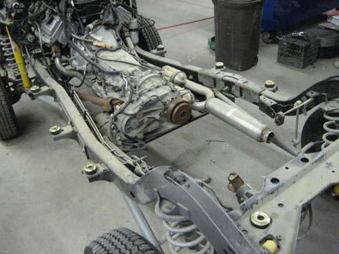
18 A. PREPARATION OF THE JEEP FRAME OVERVIEW Preparation of the Jeep frame is a simple task that most builders can perform easily. Preparing the frame to be stretched consists of: Removing the fuel system. (Fuel and evaporative emission lines and fuel tank) Removing the brake line along the frame. Cleaning the frame assembly in the areas to be modified. Mounting the cutting jig to the frame and cutting the frame in half. INSTRUCTIONS 1. Remove the fuel tank assembly. Use the quick disconnect fittings properly. 2. Cut the exhaust. Normally this is done behind the muffler. 3. At this point many builders find it helpful to remove the tub from the frame. You can leave the fenders, grill and hood in place simply by unbolting them. The wiring harness can be unplugged in the left-hand foot well from the instrument panel. Pull the harness through the large grommet in the firewall. Undo any other connected items and remove the body mounts so that you may remove the tub and windshield frame. You may remove the doors at this point to make it lighter. The emergency brake lines can be disconnected at the bracket located under the tub. If you don t have the proper tool, one can be made using a 1/2 12 point closed end wrench with a 1/8 slot cut in it so that you can slip it over the cable. Page 3 of 20


19 4. Remove the brake and fuel line bundle. Rubicon Locker Pump hose and any vapor lines on your particular year Wrangler will be lengthened with rubber hose available at any auto parts store. Be sure to get hose that is not affected by gasoline fumes for any vapor lines. 5. Clean the frame. A good job will require the area to be stretched to be free of any dirt or rust. 6. Remove the rear driveshaft. This will need to be re-tubed for the new length. We recommend waiting till you have your vehicle sitting at ride height before taking a measurement and sending the shaft to your local driveshaft shop. 7. Remove the body mounts located directly in front of the rear wheels. Take your time cutting, you will be reusing these later. Page 4 of 20

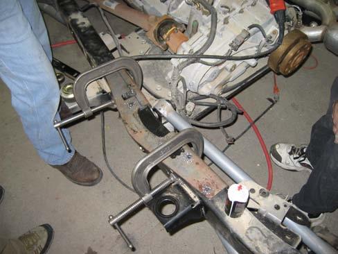
20 8. Fit the cutting jig to the frame and mark all critical locations. The cutting jig is symmetrical and designed to be used on both sides of the vehicle to locate the holes that mount the extension jigs and also to locate the cut line. Start by locating the cutting jig on the frame using C-clamps. It s not critical where the jig lies exactly, just that it fits on the frame as best as possible. Once you are satisfied with the location, FIRMLY clamp it to the frame. Scribe the cut line on the inside of the frame rail and along the top. Using your transfer punch, locate the center of the holes shown in the following diagram. Page 5 of 20

21 Page 6 of 20


22 9. Drill and tap the extension jig mounting holes. With the cutting jig still firmly clamped in place, use a 3/16 pilot bit and carefully locate the tip in the center punch mark and drill. Step up to a 1/4 bit next and finally your R Bit (21/64)(8.5mm). Take the self tapping bolts supplied in the Brute hardware Pack and carefully run them into the holes with an impact wrench. DO NOT TIGHTEN; the point of this step is to thread the holes. Repeat the procedure for the opposite frame rail. 10. Cut the frame in half. Remove the cutting jig and using the combination square, transfer the scribe line around the frame. Support either side of the frame with jack stands and carefully cut along the line. Use a Sawzall, plasma torch or gas torch. We use a Sawzall because it does the cleanest job. 11. Prep the frame ends for welding. Carefully clean all slag or burs from inside the frame rails with a file or die grinder. Using the four inch angle grinder bevel the edges of the frame rails with a 45 degree angle. Page 7 of 20


23 12. Locate the frame sleeves. Use a small tack weld to locate the frame sleeves half way into the frame openings. Remove any E-coating where the sleeves will be welded or tack welded prior to placing them into the frame. Page 8 of 20


24 13. Prepare the frame extension pieces. The extensions come E-coated to prevent corrosion. This is the same coating the rest of the frame comes with from the factory. Grind the edges with a 45 degree bevel and remove any excess paint. Using the tape measure, combination square and scribe, mark the inside center of each extension with the tube seam to the inside of the frame. You ll use this to help align the fishplates later on. Page 9 of 20

25 A. STRETCHING THE JEEP FRAME OVERVIEW Although some people find the prospect of modifying the frame a daunting task, in reality it is a very simple procedure made even easier with the supplied jigs and frame assemblies provided with your Brute kit. This procedure should only be performed by an experienced, certified welder. Welding is a skill that requires constant practice and general knowledge. Many successful Brute builders do not posses these skills and therefore find a person qualified to perform these modifications. Some builders choose to tow the rolling chassis to a shop to perform the necessary welding or by bringing in a knowledgeable welder to do the actual welding of the frame. Most of the prep work can be handled by the builder, including cutting the frame, prep work on the pieces being welded and all the finish work. The chassis can actually be moved short distances with the mid frame extensions in place and the extension jigs holding everything together to transport the chassis from shop to shop. INSTRUCTIONS 1. Install the frame extensions and extension jigs. Install the extensions with the tube seam to the inside. Using the 3/8 self tapping Page bolts, 10 install of 20the frame extension jigs over the


26 the inside. Using the 3/8 self tapping bolts, install the frame extension jigs over the extensions. Tighten by hand and adjust the frame extensions for and aft so that the gap is even. The extensions are designed to leave a gap for welding to ensure full penetration of the weld. Tighten the bolts and clamp as necessary to take up any gaps near the weld area. Page 11 of 20


27 2. Check frame dimensions. The frame jigs are a proven way to stretch the frame with minimal hassle but it s still necessary to double check the frame dimensions. 3. Weld the frame. Once you re satisfied with the frame dimensions put a heavy tack weld approximately 1/2 to 5/8 on all four corners of each frame seam. Once the frame is tack welded you can weld outside and underneath the frame. Remove the extension jigs and finish welding the frame. Use appropriate welding standards for chassis modifications. Use at least two full passes and fill the gap ensuring an even, full penetration weld. Repeat for all seams. Page 12 of 20


28 4. Install the Fishplates. Begin by grinding the inside welds smooth so that the fishplates can sit flush to the frame rail. Position each fishplate on the frame, centered vertically and horizontally on the frame extension center mark you made earlier. C-clamp the fishplate firmly in place and mark the weld areas as shown on the extension and frame. Remove the Page 13 of 20


29 firmly in place and mark the weld areas as shown on the extension and frame. Remove the fishplate and prepare the areas to be welded by removing the e-coat on both the frame and the fishplate. Weld in the positions shown. Using the fishplate as a drill guide, drill the fuel rail bundle clip holes through the frame. 5. Prime and paint the frame. Use high quality primer and chassis paint. We recommend always using a catalyzed primer and paint. 6. Install the fuel rail bundle. Use the new fuel and brake line provided in the kit. Use high quality tubing for any vapor or air lines. Page 14 of 20


30 7. Install the E-brake cables. Install Jeep Unlimited E-brake cables; part # AB & # AB for disk brakes. For drum brakes and custom applications we have found the Lokar Universal Emergency Brake cable to be easy to adapt to the Wrangler s bracket and lever. B. INSTALL THE FORWARD BED MOUNT 1. Locate the Forward Bed Mount using the measurements shown below. The holes on the A bracket of the forward Bed Mount may or may not line up with the holes in the frame depending on what year the vehicle is. USE THESE HOLES FOR REFERENCE ONLY. Loosely clamp the bracket in place and locate the height and the distance from the reference points in the frame. Page 15 of 20
31 2. Leave the Forward Bed Mount clamped or tacked in place until the Rear Frame Extension has been located. Finish welding of both pieces will take place once the Rear Frame Extension and the Forward bed mount are in place. C. INSTALL THE REAR FRAME EXTENSION 1. Prepare the rear crossmember, Rear Frame Extension and frame rails. Begin by cutting the crossmember as shown. Do not remove the center portion of th crossmember. Using a grinder, clean, straighten and bevel (45) the rear of the frame rails and the front of the extensions on the Rear Frame Extension in preparation for welding the Rear Frame Extension permanently onto the frame. Clean off the paint on the crossmember where the winch mount welds to. Page 16 of 20


32 2. Temporally mount the rear frame extension to check fit. Using eight 1/2 bolts and the fishplates, bolt the rear frame assembly to the frame. Using C-Clamps, adjust the Rear Frame Extension so that the measurements are as shown in the frame measurement diagram above. Clamp the Rear Frame Extension at the winch mount to the crossmember. 3. Check the location. Using a long straight edge, check the height locations of the body mount surfaces as shown. Check for squareness and overall length. Once you are satisfied with the position of the Rear Frame Extension, clamp everything down tightly and re-check all your measurements. Page 17 of 20


33 4. Weld the Rear Frame Extension to the frame. Tack weld the four corners at each frame joint and the winch mount to crossmember. DO NOT TACK THE FISHPLATES ON AT THIS TIME. Remove the clamps and fishplates. Weld the joints thoroughly with at least 2 passes as per welding specifications for chassis modifications. Weld the winch mount as shown. 5. Install the Rear Fishplates. Grind the outside of the Rear Frame Extension joint flush and locate the fishplates using the holes located on all the parts. Mark the weld pattern shown on both the fishplates and the frame rails. Remove the fishplates and sand the paint off of all weld areas. Relocate the fishplates and weld as shown. 6. Finish weld the Forward Bed Mount to the frame. 7. If your Brute is a , install the NVLD Bracket as shown below. Page 18 of 20

34 8. Prime and paint all weld areas and the rest of the frame extension parts. E-coat will not hold up to UV radiation and must be painted. Use high quality primer and chassis paint. We recommend always using a catalyzed primer and paint. Page 19 of 20
35 COMMENTS OR QUESTIONS? American Expedition Vehicles Phone: Website: Page 20 of 20
36 BRUTE KIT 03. Installation of the Cab Closeout Installation Guide Page 1 of 6
37 PLEASE READ BEFORE YOU START TO GUARANTEE A QUALITY INSTALLATION, WE RECOMMEND READING THESE INSTRUCTIONS THOROUGHLY BEFORE BEGINNING ANY WORK. THESE INSTRUCTIONS ASSUME A CERTAIN AMOUNT OF MECHANICAL ABILITY AND ARE NOT WRITTEN OR INTENDED FOR SOMEONE NOT FAMILIAR WITH AUTO BODY REPAIR. Required Tools 4 Grinder w/ - 80 Grit Sanding Discs - Med ScotchBright Pads (Red) Drill Motor Pilot Point Drill Bit (or) Spot Weld Cutter we recommend: - DeWalt 27/64 Pilot Point DW1927 Combination Square and Scribe Tape Measure Hammer and Block of Wood Appropriate Safety Equipment Common Hand Tools Spring Loaded Center Punch or Equivalent Hammer and Body Dolly Transfer Punches File or Die grinder 220V Wire Feed Welding Machine Page 2 of 6
38 A. INSTALLING THE CAB CLOSEOUT OVERVIEW Installation of the cab closeout is the most time consuming and technical part of the Brute build. AEV has carefully designed the cab closeout into one piece so that it can easily be installed by the average fabricator or hobbyist with minor welding experience. Some builders lack the skills to do this part of the conversion and instead choose to have a body shop install the cab closeout by taking the Jeep tub and closeout to the body shop. The process involves installing the closeout and re-welding the unit back together. The most time consuming aspect of this part of your Brute build is positioning the closeout before welding. INSTRUCTIONS 1. Place the tub back on the frame. Use the front four body mounts to hold the tub down. No need to center everything at this point, just install snug the bolts. 2. Test fit the Closeout. With two people test fit the Closeout Assembly. The Closeout door latch areas must be carefully fitted around the sport bar, do one side then the other, DO NOT SPREAD THE CLOSEOUT OVER THE SPORT BAR. The Closeout must be tipped forward in order to slip it down into place. Be sure the flange on the Pork Chop slips between the bodyside and Closeout floor on each side. Sometimes it is necessary to tap the floor down with a block of wood to fit the Closeout properly. 3. Align the Closeout in the cross car dimension. Once the Closeout is fitted, align the fourway and two-way jigging hole in the Waterfall with the Closeout floor. Once these holes are lined up, tack weld the Waterfall to the Closeout. 4. Install the Seam Doubler Plates onto the tub. Drill three 3/8 holes in both the body side and the Closeout as shown. Remove the paint in preparation for welding. Fit the Seam Doubler plates inside the body and mark the center. The Doubler Plates are made from Galvanneal Steel so the outside coating will need to be sanded along the centerline to remove the coating for a good seam weld. Plug weld the three 3/8 holes on the Tub to the Doubler Plate once you are satisfied with the fit. DO NOT WELD THE CLOSEOUT TO THE DOUBLER PLATE YET. 5. Align the Doors and bodysides. Time spent here is critical. We find that this process normally takes between 45min to 3 hours to get everything perfect. Reinstall the door strikers and nut plates. Check the fit of the doors. Adjust the door strikers so that the doors close easily and sit flush in the opening. Sight down the side of the vehicle and be Page 3 of 6
39 doors close easily and sit flush in the opening. Sight down the side of the vehicle and be sure that the doors aren t sticking out at the top or the bottom indicating that the closeout is racked to one side, or spread out at the top (two very common issues at this point). Compare the cross car measurement to your initial measurement before the tub was cut. Use a straight edge to be sure the doors are level with the body side, check in several locations. Align the Closeout in the for/aft dimension. Clamp a straight edge across the back of the Closeout assembly and check for an overall cab dimension of 61 from the front of the cab (where the fender bolts on) to the back of the cab. Check that the door sill is parallel at the seam and that there is an even parallel gap all along the bottom of the door. Clamp the bodyside to the downward facing flange on the floorpan under the doors to set the angle of the closeout. 6. Attach the J-Rails. Cut and reuse the J-rails removed earlier. Drill the hardtop mounting holes as shown and plug weld the J-rail to the Closeout using the holes drilled earlier to remove the factory spot welds. Weld the seams carefully so as not to get weld in the groove underneath where a soft top would slide in. Finish out the welds with the sander and ScotchBright pad. 7. At this point you may choose to test fit the Brute Hardtop. Install the header latches and hardware from the factory hardtop. DO NOT USE SOFT TOP OR AFTERMARKET LATCHES. Test fit and check gaps between the doors and the hard top. 8. Lock down the closeout. Once you are satisfied with the door gaps and all critical measurements: Tack weld the three holes in the Closeout bodyside to the Doubler plate. Tack weld the floorpan to the outside Waterfall sections of the closeout. Tack weld the Longitudinal Strainer of the tub and Closeout. Once everything is tacked in place, MIG weld the areas shown. Weld the Bodyside to the Floorpan. Weld the Door Opening and Latch area to the Porkchop. 9. Weld and blend the door sill return flange. Use the hammer to lightly bend the return flange on the Closeout to the return flange on the tub under the door, once its bent in, run a small MIG weld on that area. 10. Finish the seams out. Using the 80 Grit sanding disks and ScotchBright pads, finish your seam welds out as best as possible. 11. DO NOT WELD ON THE REAR CAB BODY MOUNTS AT THIS TIME. Page 4 of 6
40 B. PREP AND PAINTING THE BRUTE CAB OVERVIEW Painting your Brute is one of the most important parts of the build; after all, it s the first thing everyone notices. We recommend that a professional autobody repair facility paint your Brute. Insist on high quality paint and a two part system (base coat / clearcoat). There are several ways to locate a quality shop: You ask any shop that builds custom cars or hotrods. If the paint shop you choose does not have a downdraft spray booth and oven in their facility, we suggest you look else ware for a professional painter. Are they a member of any national organizations such as ICAR? Are they approved by insurance companies to do repair work INSTRUCTIONS 1. Use Structural Adhesive and Seam Sealer on joints and seams. Use structural adhesive such as FUSOR 480 or equivalent structural adhesive on the rear Pork Chop flange to bodyside to prevent rattles. Use FUSOR 123 or equivalent catalyzed seam sealer on all exterior joints. Tape off both sides of the seams and apply the seam sealer, once cured this seam sealer can be sanded so that the end product looks just like the factory seams. 2. Prepare the exterior spot welds and welded areas for a skim coat of autobody filler under the door and up onto the bodyside as required. Block, prime, seal and paint per autobody collision repair standards. Page 5 of 6
41 COMMENTS OR QUESTIONS? American Expedition Vehicles Phone: Website: Page 6 of 6

42 BRUTE KIT 04. The Brute Bed Installation Guide Page 1 of 7
43 PLEASE READ BEFORE YOU START TO GUARANTEE A QUALITY INSTALLATION, WE RECOMMEND READING THESE INSTRUCTIONS THOROUGHLY BEFORE BEGINNING ANY WORK. THESE INSTRUCTIONS ASSUME A CERTAIN AMOUNT OF MECHANICAL ABILITY AND ARE NOT WRITTEN OR INTENDED FOR SOMEONE NOT FAMILIAR WITH AUTO BODY REPAIR. Required Tools Drill Motor 4 Angle Grinder Tape Measure Appropriate Safety Equipment Common Hand Tools Spring Loaded Center Punch or Equivalent File or Die Grinder Page 2 of 7
44 A. PAINTING THE BED AND TAILGATE ASSEMBLIES OVERVIEW The Brute bed is delivered as an assembled unit requiring no fabrication. The bed will need to be prepared and painted. Preparation of the bed includes smoothing exterior spot welds and seam sealing all the seams. Minor assembly of the bed consists of: Installation of the fender flares Installation of the ground strap Installation of an optional spray-in urethane bed liner. Installation of the stock taillights. Minor assembly of the tailgate is required and involves: Bolting the tailgate to the bed. Installation the tailgate latches and bed support cables. Installation of the license plate bracket. The Bed assembly, once painted will be mounted to the frame and aligned with the rest of the body. This process is easy but can be time consuming to achieve a perfect fit. We generally allow two hours for alignment and any shimming if required. INSTRUCTIONS 1. Install the hinges to the tailgate using the supplied hinges and hardware provided in the Brute Hardware pack. The tailgate is now ready for paint prep and paint. 2. Drill any required holes. If you are planning on drilling any holes and or trimming the wheel openings for the AEV Highline Body Kit, bed tie downs, or any other accessory, now is the time. 3. Using the FUSOR 123 or equivalent catalyzed seam sealer, tape, seal and sand all exterior seams. 4. Prepare all spot welded areas for a light skim coat of autobody filler. Block, prime, seal and paint per autobody collision repair standards. If you are planning on using a spray-in bed liner, there is no reason to paint the inside. We recommend bringing the spray-in liner up over the rails and down the outside approximately 5/8 to 3/4 inches to line up with Page 3 of 7
45 liner up over the rails and down the outside approximately 5/8 to 3/4 inches to line up with the horizontal exterior seam in the corners of the bed. 5. It is acceptable to seam seal the exterior seams on the front of the bed and not finish out the spot welds. Page 4 of 7
46 B. INSTALLATION OF THE BRUTE BED OVERVIEW DO NOT MOUNT THE TAILGATE TO THE BED UNTIL THE BED HAS BEEN MOUNTED, AND THE ENTIRE BODY ALIGNED AND BOLTED DOWN INTO FINAL POSITION. INSTRUCTIONS 1. Insert the six rubber bed mounts. Use the two supplied in the Brute Hardware pack along with the four rear most stock body mounts as shown. 2. Place the bed onto the frame, be especially careful at the rear of the bed where it fits around the rear crossmember. Roughly align the unit by eye. 3. Run a piece of heavy utility string along the bodyline on both sides of the vehicle from the rear corner of the bed onto the door line and up as far as the cowl. This will allow you to stand at the front of the vehicle and Gunsight the bodyline down the side to align the cab and bed. This is a time consuming process as you will have to adjust the bed and the closeout separately to achieve perfect results. We typically allow for two hours for this process. Use a jack and block of wood to lift the rear of the cab if necessary. You may have to use large washers between the body mounts and the body in order to level everything out. 4. Once you have everything in alignment, weld the rear body mounts to the cab. Bolt the body mount and isolator to the body and weld in place. 5. Install the 3 spacers into the middle body mounts. Tighten all body mounts. 6. Install the Ground strap from the exhaust hanger bolt to the bed crossmember directly above the middle exhaust hanger. 7. Install the latches and cables onto the tailgate. The inside portion of the latch must be trimmed approximately 0.5 in order to fit into the inner portion of the tailgate. Bolt the cables on so that the ear on the cable ends directs the cable to fold downward when the gate is closed. DO NOT OVERTIGHTEN THE CABLE BOLTS. THEY MUST BE ABLE TO SWING FREELY. 8. Install the rubber bumpers into the tailgate tabs on the bed. Page 5 of 7
47 9. Bolt the tailgate to the bed using the supplied hardware and nut plates. Center the tailgate so that the gaps are even on both sides and the gate is level at the bodylines with the bed. Design gap on either side is Install the license plate bracket. Wire the LED light to the stock tailgate connectors from the CHMSL in the donor vehicle. 11. Install the flares and taillights from the donor vehicle. Page 6 of 7
48 COMMENTS OR QUESTIONS? American Expedition Vehicles Phone: Website: Page 7 of 7

49 BRUTE KIT 05. Installation of the Brute Hardtop Installation Guide Page 1 of 8
50 PLEASE READ BEFORE YOU START TO GUARANTEE A QUALITY INSTALLATION, WE RECOMMEND READING THESE INSTRUCTIONS THOROUGHLY BEFORE BEGINNING ANY WORK. THESE INSTRUCTIONS ASSUME A CERTAIN AMOUNT OF MECHANICAL ABILITY AND ARE NOT WRITTEN OR INTENDED FOR SOMEONE NOT FAMILIAR WITH AUTO BODY REPAIR. Required Tools Drill Motor 1/2 Step Drill Bit 5/16 Drill Bit Sanding Supplies Urethane Glass Installation Tools Wiring Tools Painting Tools and Supplies Medium Clamps Page 2 of 8
51 A. FITTING THE TOP TO THE VEHICLE OVERVIEW The Brute Hardtop comes as an assembled unit with the exterior portion of the top finished in a grey sanding gel coat, while the interior of the top is left in a white natural resin finish. Installing the hardtop is generally a relatively easy task that consists of only a few steps. The hardtop must: be fit to the vehicle. be painted. have the glass installed. have all the hardware put on. have the interior lights and CHMSL installed. INSTRUCTIONS 1. Once your cab closeout is fully welded out and finished, install the hard doors, door striker plates and header seal. Begin by temporarily installing the header latches (do not cross thread the bolts nor over tighten them) to the hardtop and test fit the top. At this point, check to be sure the top is sitting down on the J-rails all around the side and back of the top. Temporarily clamp the sides of the top into position. Clamp the header down, not to worry if it makes some cracking noises on this first clamp down, it s just everything settling in and will do no damage. Check the fit around the doors, windshield frame and the rear of the vehicle. The doors and windshield frame can be adjusted, but do everything in a slow meticulous fashion. Often times the top might look high initially, but tends to settle in once it s bolted into position and the seals take a set. Once you are satisfied with the fit of the top, mark the bolt hole locations and drill the J-rail in the hardtop out to 1/2. 2. Prior to painting the top you may wish to dry fit any accessories you plan to mount to the center console like radios, additional lighting, switches, etc. Page 3 of 8
52 B. PAINTING THE TOP OVERVIEW The Brute s hardtop can be painted in a number of ways and the builder has many options. AEV typically recommends using a medium to course spray texture and base coat on the outside with or without a clearcoat. The inside is typically sprayed with a fine texture and painted with a base coat only, however some builders have successfully used other methods such as spray in urethane bed liner or carpet like found in many pickup canopies and speaker boxes although the carpet can be a little trickier to trim the edges properly. Common questions regarding the Brute top involve painting; one common question is if the top can be left smooth and painted to match the vehicle s base coat / clear coat finish. The answer is yes it can be painted smooth to match the vehicle but it can t simply be scuffed and painted. The painter will need to sand and block so that flow marks from the manufacturing process and wows in the composite surface do not show through. This type of finish is often best left for professional body shops that specialize in painting composite components. Another common question is if one can paint the Brute top black on a colored vehicle like the factory does. Of course it can be painted black, however it is generally concurred that it doesn t look very good because it is distracting to the lines of the Brute. The top of the bed was intentionally raised to trick ones eye into believing the vehicle is shorter than it really is. By painting the top black, visually you are splitting the car up and it will cause the illusion that the vehicle is bent in the middle or just not proportioned correctly. Regardless of how and what color the top is painted, be sure to lightly sand or scuff the entire top to ensure the paint adheres properly. Its not required, but for a tidier appearance all seams, including the inside seams can be sealed with a high quality sealer such as FUSOR 123 but should not be filled and sanded smooth. INSTRUCTIONS 1. Prepare the top for paint. Lightly sand the exterior of the top with a grit Dual Action Sander (DA). If you plan on painting the interior, use a good wax and degreaser and a red ScotchBright Pad to lightly scuff the interior (if there is any shine to the surface the interior paint will not stick.) 2. Texture the top if desired. For an OE look textured top, use Standox Stone Chip Primer (Part #11344) or equivalent and apply per instructions to achieve a similar texture to the OE top. Textured tops tend to be much more durable and show less surface irregularities (which is why they are textured from the factory). If you are looking for a smooth finish, we recommend bolting the top down, aligning the seams and checking for wows in the surface. Any wows must be filled and blocked to provide a quality finish. Page 4 of 8
53 3. Paint the exterior using the same catalyzed base coat as the body uses. You can leave it this way for easy repairs and a flat finish, you can clear coat it with a flattening agent, or you can clear coat it with the texture. Most paint shops will spray various test cards so that you can achieve the finish you are looking for. 4. Painting the interior. The interior can be painted the same color as the dash board (use the interior paint code located on the door or upper front door sill). The interior can be left the neutral composite color or even carpeted with speaker carpet. C. INSTALLATION OF THE GLASS Installation of the glass is straightforward. Most builders take the painted top to a qualified auto glass installation specialist to have the glass installed. Often this is the best solution because most builders lack the specialized urethane guns and trim equipment required. The top lites are designed to be installed with high quality, quick set urethane without any trim. Use a urethane primer on the frit (the black baked on coating on the glass) designed to work with the urethane you plan to use. The rear window is designed to have a molding placed around the glass with the seam located at the bottom, center of the rear glass. Again, be sure to use a matched primer and urethane. After applying the urethane, use high quality glass tape (designed not to take the paint off) to tape the windows in place until cured. The top lites are slightly curved and will flex into position once the windows are taped into place. D. TOP HARDWARE Installation of the top hardware consists of the latches and handles. Install the OE header latches using the bolts from the donor vehicle. Install the handles in the side by locating the (4) 1/4-20 countersunk stainless hex head bolts, nuts and washers in the Brute hardware pack. Use the supplied hardware to bolt the handles in place. Do not over tighten. E. WIRING THE TOP AND INSTALLING THE CHMSL The Brute top is designed to use the overhead lights from the sound-pods that come standard in Jeep Wranglers. If your donor vehicle is an older unit, you will need to order the lens part # AA (lens) and part # AD (lamp). You ll need to strip the light and the wiring from the sound-pod and connect the wires as shown below. Remove the lights and modify the connector as also shown below and reuse the existing screws from the donor. The CHMSL (Center High Mount Stop Lamp) Page is reused 5 of 8 from the donor vehicle. Unscrew the unit


54 CHMSL (Center High Mount Stop Lamp) is reused from the donor vehicle. Unscrew the unit from the stock spare tire carrier assembly and remove the socket with as much wiring as possible from the stock tire carrier. Run the wiring through the top and then mount the CHMSL to the Brute top. Use a connector such as Mopar part # AA and mating connector Mopar part # AA to route all connections for the interior lights, CHMSL and any other accessories through so that the top can be removed easily. Page 6 of 8
55 Page 7 of 8
56 COMMENTS OR QUESTIONS? American Expedition Vehicles Phone: Website: Page 8 of 8
PROVEN WORLDWIDE SNORKEL FOR CHEVY COLORADO NEW PRODUCT
 AEV30272AC Last Updated: 10/09/18 PROVEN WORLDWIDE SNORKEL FOR CHEVY COLORADO NEW PRODUCT Please visit www.aev-conversions.com to view the most current installation guide for this product. This is a new
Installation for Full Size Polaris Ranger Crew Doors
 Installation for Full Size Polaris Ranger Crew Doors Order of Installation: Heater Doors Wiper on to Windshield Windshield Top & Back Panel Note: Most of the steps in these instructions need to be repeated
TUBULAR FRONT END KIT INSTALLATION INSTRUCTIONS MUSTANG
 TUBULAR FRONT END KIT INSTALLATION INSTRUCTIONS 1979 2004 MUSTANG Pre-Installation Notes & Recommendations: Before disassembly, remove anything within the engine bay that can be removed; this will give
CUT OUT FLARES INSTALLATION INSTRUCTIONS FOR 20017, 20018, F100-F150 F250-F350 P.U. & BRONCO CUT OUTS
 20017 04/22/03 REV-A CUT OUT FLARES INSTALLATION INSTRUCTIONS FOR 20017, 20018, F100-F150 F250-F350 P.U. & BRONCO CUT OUTS Tools Required for Installation: (A) 3/16 Drill Bit (B) Pop-Rivet Gun (C) Air
Included in Hardware Kit. Jeep Cut-Out Fender Flare Set of 4 Set Part # Rev STEP 1 PRIOR TO INSTALLATION
 Jeep Cut-Out Fender Flare Set of 4 Set Part #10926-07 Rev-01 09-11-12 STEP 1 PRIOR TO INSTALLATION A) Bushwacker only approves installing the flares according to these written instructions with the hardware
INSTALLATION GUIDE PREMIUM FRONT BUMPER. AEV30103AE Last Updated: 09/08/14 US PATENTS: D683281, D CHINESE PATENT: ZL
 PREMIUM FRONT BUMPER US PATENTS: D683281, D697842 CHINESE PATENT: ZL 2012 3 0026081.4 AEV30103AE Last Updated: 09/08/14 INSTALLATION GUIDE PLEASE READ BEFORE YOU START TO GUARANTEE A QUALITY INSTALLATION,
======================================================================================== ( DR / DR) JK WRANGLER MOD RACK
 JK WRANGLER MOD RACK") (10984 4DR / 10982 2DR) JK WRANGLER MOD RACK INSTALLATION SHEET Important Notes: Some brands of windshield light brackets and snorkels may not be compatible with the 10984 MOD Rack System. Body lifts are
(10984 4DR / 10982 2DR) JK WRANGLER MOD RACK INSTALLATION SHEET Important Notes: Some brands of windshield light brackets and snorkels may not be compatible with the 10984 MOD Rack System. Body lifts are
WEAR SAFETY GLASSES WHEN INSTALLING THIS KIT.
 INSTALLATION INSTRUCTIONS Trans4mer Mounting Systems Part No. 29753 (black) Part No. 65654 (stainless) for full size GM pickups, and Blazer, Yukon, Suburban, Tahoe As you read these instructions, you will
JK Brawler Rockers. *Includes ONE of the Hardware Kits (not both)
") INSTALLATION INSTRUCTIONS INST-17-08-200_A JK Brawler Rockers IMPORTANT: Thank you for purchasing this Poison Spyder product. Please read through this entire document before proceeding with installation.
INSTALLATION INSTRUCTIONS INST-17-08-200_A JK Brawler Rockers IMPORTANT: Thank you for purchasing this Poison Spyder product. Please read through this entire document before proceeding with installation.
RH-412 STEEL DOORS INSTALLATION INSTRUCTIONS
 RH-412 STEEL DOORS INSTALLATION INSTRUCTIONS By following the steps outlined below, the assembly, installation and adjustment of the steel doors, will be a simple process. Let s start with the Driver Side.
JK Crusher Corners. *Includes ONE of the Hardware Kits (not both)
") INSTALLATION INSTRUCTIONS INST-18-05-020_A JK Crusher Corners IMPORTANT: Thank you for purchasing this Poison Spyder product. Please read through this entire document before proceeding with installation.
INSTALLATION INSTRUCTIONS INST-18-05-020_A JK Crusher Corners IMPORTANT: Thank you for purchasing this Poison Spyder product. Please read through this entire document before proceeding with installation.
JK Rear Crusher Flares
 INSTALLATION INSTRUCTIONS INST-17-05-010_A JK Rear Crusher Flares IMPORTANT: Thank you for purchasing this Poison Spyder product. Please read through this entire document before proceeding with installation.
ASSEMBLY INSTRUCTIONS FOR MAR-K BEDSIDES AND GM FLUSH TAILGATE WITH HANDLE
 ASSEMBLY INSTRUCTIONS FOR MAR-K BEDSIDES AND 41-53 GM FLUSH TAILGATE WITH HANDLE Build the box assembly according to the MAR-K assembly instructions. When installing the tailgate and latching mechanisms
General Prisoner Transport Install Instructions PT-2-INST
 General Prisoner Transport Install Instructions PT-2-INST 50 or 60 high x 80, 100 & 120 inch long / Double Compartment Inserts Also refer to PT-A-3XX instructions for vehicle specific mounting measurements
Important Note. Tools Required: Welder capable of fully welding 10 GA.135 steel
 INSTALLATION INSTRUCTIONS Frame Reinforcement Kit 11100 (Patent Pending) 1968-72 GM A-Body Coupe/Sedan Read Instructions FULLY before starting Installation Important Note Installation of this kit requires
SAVVY OFF ROAD GAS TANK SKID INSTALLATION INSTRUCTIONS
 It is best to work with a fuel tank that has the least amount of fuel in it as possible. Thank you for purchasing the best skid on the market. Please follow these instructions and your installation should
MM Strut Tower Brace, Cobra (MMSTB-7)
") The MM strut Tower Brace attaches to each strut tower and to the firewall. 3430 Sacramento Dr., Unit D San Luis Obispo, CA 93401 Telephone: 805/544-8748 Fax: 805/544-8645 www.maximummotorsports.com MM
The MM strut Tower Brace attaches to each strut tower and to the firewall. 3430 Sacramento Dr., Unit D San Luis Obispo, CA 93401 Telephone: 805/544-8748 Fax: 805/544-8645 www.maximummotorsports.com MM
Rubber Grommet, 36 pcs. 3/4 Screw, 10 pcs. Nut, 10 pcs
 Jeep Cherokee ZJ Set Part #10916-07 Rev-2 03-11-10 THESE INSTRUCTIONS INVOLVE CUTTING THE FENDERS OF THE VEHICLE. IT IS IMPORTANT TO READ ALL INSTRUCTIONS PRIOR TO THE CUTTING AND INSTALLATION OF THESE
PLEASE READ INSTRUCTIONS THOROUGHLY BEFORE PROCEEDING
 Part No. 8870 -or Part No. 9100-9110 Front Fender Flares Flat Panel Design 07-09 Jeep JK, 2/4 Dr. PLEASE READ INSTRUCTIONS THOROUGHLY BEFORE PROCEEDING We have provided complete instructions and specific
JK Front Crusher Flares
 INSTALLATION INSTRUCTIONS INST-17-03-030_A JK Front Crusher Flares IMPORTANT: Thank you for purchasing this Poison Spyder product. Please read through this entire document before proceeding with installation.
Bushwacker Jeep Flat Style Fender Flares Front Pair
 Bushwacker Jeep Flat Style Fender Flares Front Pair Note: These instructions involve cutting parts of your vehicle. Please read all instructions prior to starting. Installation Time: 3-4 Hours Tools Required:
INSTALLATION INSTRUCTIONS RH 412 STEEL DOORS
 By following the steps outlined below, the assembly, installation and adjustment of the steel doors, will be a simple process. Let s start with the Driver Side. Note: Having the hood open makes the job
Roof Rack Installation Instructions
 Roof Rack Installation Instructions CAUTION: Do not use the mounting hardware contained in this roof rack kit for installation on Fiberglass or Composite Plastic surfaces. Supplemental hardware pack, part#
YJ DeFenders. These installation instructions apply to the following Poison Spyder products:
 INSTALLATION INSTRUCTIONS INST-13-02-070_A YJ DeFenders IMPORTANT: Thank you for purchasing this Poison Spyder product. Please read through this entire document before proceeding with installation. If
Installation Instructions Kit, Base Rail Bracket Part # 31413
 Installation Instructions Kit, Base Rail Bracket Part # 31413 Dealer / Installer: Provide a copy of these Instructions to the end user of this product. These Instructions provide important operating and
INSTALLATION INSTRUCTIONS
 INSTALLATION INSTRUCTIONS Trans4mer Gen II Mount System For 2008 Ford Super Duty Kit 80140 (Large Frame Black) and Kit 80150 (Mid Frame Black) and Kit 80155 (Mid Frame Stainless) Your safety, and the safety
Jeep Cherokee Door XJ Set Part # Revision J
 Jeep Cherokee 84-96 4 Door XJ Set Part # 10911 Revision J 6-5-06 Step 1: Prior to Installation: A) Fit: Verify the fit of the flares to vehicle. (Some filing, sanding, or cutting may be necessary to ensure
INSTALLATION & OWNER S MANUAL
 Rev. O p. 1 of 16 INSTALLATION & OWNER S MANUAL V4213 BALL CAGE KIT INSTALLATION & OWNER S MANUAL The contents of this envelope are the property of the owner. Be sure to leave with the owner when installation
Ford Pick Up Rear leaf Spring Kit Installation Instructions
 1948-1956 Ford Pick Up Rear leaf Spring Kit Installation Instructions 1-800-984-6259 www.totalcostinvolved.com Parts 48 inch leaf (2) springs (4) U-bolts 3/8-24 x l 1/4bolts (16) & nuts (2) 1/2-20 x 4
Jeep. Cut-Out Fender Flares Set of 4. Included in Hardware Kit: Set Part # Rev-8 06/29/16 STEP 1 PRIOR TO INSTALLATION
 STEP 1 PRIOR TO INSTALLATION A) Bushwacker only approves installing the flares according to these written instructions with the hardware provided. WARNING: Failure to install according to these instructions
Important Note. Tools Required: Welder capable of fully welding 10 GA.135 steel
 INSTALLATION INSTRUCTIONS Frame Reinforcement Kit 11102 (Patent Pending) 1964-67 GM A-Body Coupe/2dr Sedan Read Instructions FULLY before starting Installation Important Note Installation of this kit requires
C4 Fabrication Rock Slider Installation 14+ 5th Gen 4Runner w/o KDSS
 C4 Fabrication Rock Slider Installation 14+ 5th Gen 4Runner w/o KDSS Thank you for your purchase of the C4 Fabrication s 5th Gen 4Runner Rock Sliders! This product was carefully crafted to ensure a perfect
Jeep Cherokee 4-Door XJ Set Part # Rev
 Jeep Cherokee 4-Door XJ Set Part # 10911 Rev-14 04-05-10 Step 1: Prior to Installation: A) Bushwacker only approves installing the flares according to these written instructions with the hardware provided.
Hatchback Wing Riser Kit
 Hatchback Wing Riser Kit 2015-06-11 Thank you for purchasing this PERRIN product for your car! Installation of this product should only be performed by persons experienced with installation of aftermarket
Installation Guide for Rough Country 1.25 inch Body Lift Kit w/o Shocks (07-15 Wrangler JK 4 Door) Item # J10048 Option B; Manual
 Item # J10048 Option B; Manual") Installation Guide for Rough Country 1.25 inch Body Lift Kit w/o Shocks (07-15 Wrangler JK 4 Door) Item # J10048 Option B; Manual Installation Time: 3 Hours Tools Required: Jack (Tall enough to reach body
Installation Guide for Rough Country 1.25 inch Body Lift Kit w/o Shocks (07-15 Wrangler JK 4 Door) Item # J10048 Option B; Manual Installation Time: 3 Hours Tools Required: Jack (Tall enough to reach body
Bushwacker Jeep Flat Style Fender Flares Rear Pair (JK Wrangler 2dr)
") Bushwacker Jeep Flat Style Fender Flares Rear Pair (JK Wrangler 2dr) Note: These instructions involve cutting parts of your vehicle. Please read all instructions prior to starting. Installation Time: 3-4
Bushwacker Jeep Flat Style Fender Flares Rear Pair (JK Wrangler 2dr) Note: These instructions involve cutting parts of your vehicle. Please read all instructions prior to starting. Installation Time: 3-4
Chevy Colorado. INSTALLATION GUIDE Front Bumper
 Chevy Colorado INSTALLATION GUIDE Front Bumper FIG 1A First, we ll start by removing the small allen bolts from the inside fender wells that hold the stock front bumper in place. FIG 1B You will also need
WARNING. Failure to observe these instructions could lead to severe injury or death.
 INSTALLATION INSTRUCTIONS WINCH MOUNTING KIT Part Number: 80156, 80160 Application: 2008 Ford F150 Your safety, and the safety of others, is very important. To help you make informed decisions about safety,
IMPORTANT: PLEASE RETAIN THIS INSTRUCTION MANUAL FOR FUTURE REFERENCE
 IMPORTANT: PLEASE RETAIN THIS INSTRUCTION MANUAL FOR FUTURE REFERENCE 005-07 Cadillac STS Classic 3D Z, Classic Dual Weave, Classic Mesh & Classic Black Mesh Grilles B 7 HR 3 STS Classic 3D Z Grille Part
Jeep. Flat Style Fender Flares Front Pair. Included in Hardware Kit:
 Jeep Flat Style Fender Flares Front Pair STEP 1 PRIOR TO INSTALLATION A) Bushwacker only approves installing the fl ares according to these written instructions with the hardware provided. WARNING: Failure
Body Repair. Collision Repair. Specification. Fastener Specifications Fastener Specifications. Blind Rivet. Flow Drill Screw (FDS) Torque FDS
 Torque FDS") Body Repair Collision Repair Specifications Fastener Specifications Fastener Specifications Application Specification Metric English Cross-Car Brace Mounting Bolts 25 Y 18 lb ft Windshield Frame Mounting
Body Repair Collision Repair Specifications Fastener Specifications Fastener Specifications Application Specification Metric English Cross-Car Brace Mounting Bolts 25 Y 18 lb ft Windshield Frame Mounting
2010+ Dodge Ram 2500/3500 Front Bumper Install Instructions
 2010+ Dodge Ram 2500/3500 Front Bumper Install Instructions Warning! Read the instructions completely before beginning the installation. Before tightening bolts, drilling or cutting where required, check
All Terrain Flares 2014 Chevy Silverado
 Page 1/8 Components: 1. Front Flares (2) 2. Rear Flares (2) Tools required: - Utility knife - #2 Phillips driver - Socket wrench - 13 mm Socket - 6 mm Allen Wrench - T-15 Torx bit - Trim Removal Tool -
Jeep. Flat Style Fender Flares Set of 4. Included in Hardware Kit: STEP 1 PRIOR TO INSTALLATION. Set Part # Rev-3 1/11/2016
 STEP 1 PRIOR TO INSTALLATION A) Bushwacker only approves installing the fl ares according to these written instructions with the hardware provided. WARNING: Failure to install according to these instructions
*Patent Pending. *Trademarked. Series II. Glass Conversion Kit. (888) One-Products (888)
 One-Products (888)") *Patent Pending *Trademarked Series II Glass Conversion Kit www.onepieceproducts.com (888) One-Products (888) 663-7763 Installation Manual Full One Piece Door Glass Conversion Kit Series II 1967-1972 Chevy
*Patent Pending *Trademarked Series II Glass Conversion Kit www.onepieceproducts.com (888) One-Products (888) 663-7763 Installation Manual Full One Piece Door Glass Conversion Kit Series II 1967-1972 Chevy
Ford F150 Front Bumper
 2009-2011 Ford F150 Front Bumper Warning! Read the instructions completely before beginning the installation. Before tightening bolts, drilling or cutting where required, check to make sure that there
INSTALLATION INSTRUCTIONS
 INSTALLATION INSTRUCTIONS Trans4mer Mounting System Dodge Ram Kit No. 65220, 73132, 75525, 76253 (black) or 65221, 73133, 75530, 76254 (stainless) As you read these instructions, you will see NOTES, CAUTIONS
How to Install Decklids and Tailbases
 All decklids and tailbases are installed in the same general way. Follow these step by step instructions to hang them the way the pros do. 1. Open the shipping containor and check for any damage to the
Cut-Out Fender Flares Rear Pair. Jeep. Included in Hardware Kit:
 Jeep Cut-Out Fender Flares Rear Pair STEP 1 PRIOR TO INSTALLATION A) Bushwacker only approves installing the fl ares according to these written instructions with the hardware provided. WARNING: Failure
Slide the stock rubber tank mount caps onto the ends of the CS-1 tank mount:
 RYCA CS-1 BODY PARTS INSTALLATION GUIDE [The CS-1 installation guides should be used as supplements to the videos found on our Youtube Channel. There is no strict order to the build process, but it is
Installation Instructions
 86-95 Suzuki Samurai LROR Sport Cage Front (SKU# SRC-SCF) Installation Instructions Front and Rear Cage Combined CAUTION: Safety glasses should be worn at all times when working with vehicles and related
Barricade Trail Force HD Rear Bumper w/ Tire Carrier installation (07-16 Wrangler JK)
") Barricade Trail Force HD Rear Bumper w/ Tire Carrier installation (07-16 Wrangler JK) Installation Time: 2-3 Hours Tools Required: Tire iron Ratcheting socket set (ratchet plus 13, 16, 19mm sockets) Open
Barricade Trail Force HD Rear Bumper w/ Tire Carrier installation (07-16 Wrangler JK) Installation Time: 2-3 Hours Tools Required: Tire iron Ratcheting socket set (ratchet plus 13, 16, 19mm sockets) Open
MMD Convertible Styling Bar Customer Installation Guide
 MMD Convertible Styling Bar Customer Installation Guide TOOLS REQUIRED/RECOMMENDED: Electric Drill 1 Forstner Bit (Hole Saw) 1 3/8 Hole Saw (manual calls for 1 ¾ ) 1/8, 3/8 & ¾ Drill Bits Rivet Gun Trim
Rugged Ridge Body Armor Guard Kit, 5 Pieces, Black (07-Current JK 4-door)
") Rugged Ridge Body Armor Guard Kit, 5 Pieces, Black (07-Current JK 4-door) Installation Time: 60 Minutes Tools Required: Notes: Phillips head screwdriver 3/8 socket or Flat head screwdriver 1/2 socket 7
Rugged Ridge Body Armor Guard Kit, 5 Pieces, Black (07-Current JK 4-door) Installation Time: 60 Minutes Tools Required: Notes: Phillips head screwdriver 3/8 socket or Flat head screwdriver 1/2 socket 7
1/4 Rubber Spacer, 26 pcs. M5-.8 Machine Screw, 26 pcs 13. Female Wire Connector, 4 pcs
 97-06 Jeep Wrangler TJ Set Part #10920-07 Rev-3 12-15-08 A) B) C) D) E) F) G) STEP 1 - PRIOR TO INSTALLATION Bushwacker only approves installing the fl ares according to these written instructions with
Jeep Wrangler JK & 4-Door Front Pair Part # Revision H
 Jeep Wrangler JK 2007 2 & 4-Door Front Pair Part # 10045 Revision H 03-25-09 Step 1: Prior to Installation: A) Bushwacker only approves installing the flares according to these written instructions with
Kawasaki Teryx 750 Cab Kit* Caution: Before using this product, read this manual and follow all Safety Instructions.
 Owner s Manual Model: Kawasaki Teryx 750 Kawasaki Teryx 750 Cab Kit* Caution: Before using this product, read this manual and follow all Safety Instructions. Safety Instructions Cab Kit Contents Hardware
ACCESS COVER INSTALLATION INSTRUCTIONS (Kit #601 for 2006 Honda Ridgeline)
") ACCESS COVER INSTALLATION INSTRUCTIONS (Kit #601 for 2006 Honda Ridgeline) NOTE TO INSTALLER: IMPORTANT READ BEFORE ATTEMPTING INSTALLATION. Allow extra time, up to 2 hours to install this cover. Disassembly
ACCESS COVER INSTALLATION INSTRUCTIONS (Kit #601 for 2006 Honda Ridgeline) NOTE TO INSTALLER: IMPORTANT READ BEFORE ATTEMPTING INSTALLATION. Allow extra time, up to 2 hours to install this cover. Disassembly
INSTALLATION INSTRUCTIONS
 INSTALLATION INSTRUCTIONS Trans4mer Grille Guard/Winch Mount Kit 6334 For Chevrolet Silverado 500HD & 3500 This WARN Trans4mer system can be customized to give your Chevy Silverado a wide variety of looks,
INSTALLATION INSTRUCTIONS
 INSTALLATION INSTRUCTIONS Trans4mer Grille Guard/Winch Mount For Chevrolet Silverado 1500HD & 2500 Kit 68162 This WARN Trans4mer system can be customized to give your Chevy Silverado a wide variety of
1104. Clean up the door striker plates with a hand grinder using a wire brush and WD-40.
 Chapter 31 - Misc. Putting VW Back Together (Video Clip 31) 1104. Clean up the door striker plates with a hand grinder using a wire brush and WD-40. 1105. Install both door striker plates on the VW body
FOR PROFESSIONAL GARAGE DOOR INSTALLERS
 Composite Garage Doors Installation Instructions FOR PROFESSIONAL GARAGE DOOR INSTALLERS Tools required Screwdriver Claw Hammer Locking Pliers Power Drill Level with a 3/32" Drill Bit Utility Knife 9/16",
Installation Instructions Universal Crossmember Kit - 60 Track Width BEFORE Measure Twice, Weld Once! II
 Installation Instructions Universal Crossmember Kit - 60 Track Width Please read these instructions completely BEFORE starting your installation. Remember the basic rule for a successful installation:
Please read BOTH these Installation Instructions and the General Towing Instructions before attempting to install or operate this equipment.
 2005-08 Pontiac G6 GT Please read BOTH these and the General Towing Instructions before attempting to install or operate this equipment. 1. Blue Ox towing products and accessories are intended to be installed
SAFETY THIS PRODUCT IS FOR OFFROAD USE ONLY. ALL LIABILITY FOR INSTALLATION AND USE RESTS WITH THE OWNER.
 SAFETY Your safety and the safety of others is very important. In order to help you make informed decisions about safety, we have provided installation instructions and other information. These instructions
TOOL LIST FOR TAILGATE HIDDEN LATCH & LINK ASSY FOR FORD FLARESIDE TRUCKS
 TOOL LIST FOR TAILGATE HIDDEN LATCH & LINK ASSY FOR 53-87 FORD FLARESIDE TRUCKS Vise Grip Clamps C-clamps Sharpie Marker Ball Peen Hammer Center Punch 3/8 or 1/2 Drill 5/32, 7/32, 9/32, and 3/8 Drill Bits
BMW E46 Coupe 3dr MP Bolt in (BMW Race Days Only) Roll Cage (B045) Fitting Instructions
 Roll Cage (B045) Fitting Instructions") BMW E46 Coupe 3dr MP Bolt in (BMW Race Days Only) Roll Cage (B045) Fitting Instructions Unwrap the mounting points/ends of the roll cage and unpack the individual fitting kits. Try to leave wrapping on
BMW E46 Coupe 3dr MP Bolt in (BMW Race Days Only) Roll Cage (B045) Fitting Instructions Unwrap the mounting points/ends of the roll cage and unpack the individual fitting kits. Try to leave wrapping on
Hardware and Components:
 Hardware and Components: (A) 5/16 x 2 Hex Bolt (B) 5/16 x 2-1/4 Hex Bolt (C) 5/16 x 2-1/2 Hex Bolt (D) 4X 5/16 x 3/4 Hex Bolt (E) 4X 5/16 x 1-1/4 Hex Bolt (F) 11X 5/16 Flat Washer (G) 12X 5/16 Nylock Nut
5/16 Hex Head Bolt, 16 pcs. Plastic Push Retainer, 6 pcs. Alcohol Wipe, 2 pcs. Side Refl ex Reflector, 2 pcs
 STEP 1 PRIOR TO INSTALLATION A) Bushwacker only approves installing the fl ares according to these written instructions with the hardware provided. WARNING: Failure to install according to these instructions
TOYOTA TACOMA LED BED LIGHTS Preparation
 Preparation Part Number: PT948-35160 Kit Contents Item # Quantity Reqd. Description 1 1 Hardware Kit 2 1 Driver Side LED assembly 3 1 Passenger Side LED assembly 4 1 Main Wire Harness Hardware Bag Contents
Master Your Terrain. (307)
") Master Your Terrain (307) 775 9565 www.tntcustoms.com Rear Swing-out Tire Carrier Jeep TJ/LJ Installation Instructions Congratulations for purchasing a T&T Customs, Inc. Rear Swing-out Tire Carrier for
Master Your Terrain (307) 775 9565 www.tntcustoms.com Rear Swing-out Tire Carrier Jeep TJ/LJ Installation Instructions Congratulations for purchasing a T&T Customs, Inc. Rear Swing-out Tire Carrier for
Installation Instructions Kit, Base Rail Bracket Part # 31413
 Installation Instructions Kit, Base Rail Bracket Part # 31413 Dealer / Installer: End User: Provide a copy of these Instructions to the end user of this product. These Instructions provide important operating
MM Strut Tower Brace, GT (MMSTB-5.1)
") 3430 Sacramento Dr., Unit D San Luis Obispo, CA 93401 Telephone: 805/544-8748 Fax: 805/544-8645 www.maximummotorsports.com MM Strut Tower Brace, 1996-97 GT (MMSTB-5.1) MMSTB-5.1 is for 1996-97 GT s with
3430 Sacramento Dr., Unit D San Luis Obispo, CA 93401 Telephone: 805/544-8748 Fax: 805/544-8645 www.maximummotorsports.com MM Strut Tower Brace, 1996-97 GT (MMSTB-5.1) MMSTB-5.1 is for 1996-97 GT s with
JK Rear Inner Fenders
 INSTALLATION INSTRUCTIONS INST-17-05-080_A JK Rear Inner Fenders IMPORTANT: Thank you for purchasing this Poison Spyder product. Please read through this entire document before proceeding with installation.
C70 Window Roller Repair Taken from: Heres the problem:
 C70 Window Roller Repair Taken from: http://www.volvospeed.com/vs_forum/topic/115086-how-to-c70-window-rollers-permanent-fix/ Heres the problem: This happened to two separate window assemblys on my c70
Frameless Fixed Panel Slider
 INSTALLATION INSTRUCTIONS Frameless Fixed Panel Slider QCI-5279 SINGLE ROLLER WITH ANTI-JUMP DOUBLE ROLLERS QCI5279 Rev Page Certified 08/09/6 Tools: To install your New Shower Enclosure, you may need
Elite Series Fender Flares
 Page 1 of 8 Installation Instructions I - Sheet Number I606RPG Rev.B Important Safety Information Tools Required Contents Elite Series Fender Flares Preparation Before Painting / Installation NOTE Actual
WPS crew Doors Installation instructions
 WPS-132-133 crew Doors Installation instructions ORDER OF INSTALLATION FOR A COMPLETE ENCLOSURE OF A CREW WPS (Weather Protection System) IS AS FOLLOWS: 1. Heater 2. Rear Thresholds - Right Hand & Left
Installation Instructions
 DODGE RAM 2500 20K Industry Standard SuperRail Custom Mounting Kit #2336 Gross Trailer Weight (Maximum)...20,000 lbs. Vertical Load Weight (Max. Pin Weight)...5,000 lbs. SYSTEM TOW CAPACITY Please note,
XJ Coil Conversion Rear 4 Link Instructions
 Parts Checklist: Iron Rock Logo Decal 10001 (2) Rock-Link Decal 13287 (2) ironrockoffroad.com Decal (1) LCA/UCA Mounting Subframe 91162 (1) Shock crossmember 91173 (1) Shock crossmember spacer 91178 (2)
`48-`56 Ford Pickup Rear leaf Spring Kit Installation Instructions Tech Line:
 `48-`56 Ford Pickup Rear leaf Spring Kit Installation Instructions Tech Line: 1-855-693-1259 www.totalcostinvolved.com CHECK ALL PARTS INCLUDED IN THIS KIT TO THE PARTS LIST BEFORE INSTALLING THE KIT.
INSTALLATION INSTRUCTIONS
 INSTALLATION INSTRUCTIONS Trans4mer Winch Mount For 2007-2010 Chevrolet Silverado HD and GMC Sierra HD Bracket Kit 90140 Your safety, and the safety of others, is very important. To help you make informed
JK Titan Tub Armor 2 and 4 Door
 JK Titan Tub Armor 2 and 4 Door Thank you for purchasing one of our quality products. From product conception to the moment we packaged this product our focus has been on providing you with the very best.
MODULAR BUMPER INSTALLATION MANUAL
 MODULAR BUMPER INSTALLATION MANUAL Parts List* 1 Center section 1 Side extension, passenger / right 1 Side extension, driver / left 1 Side cap, passenger / right 1 Side cap, driver / left 1 Brush guard,
RangerWare Fiberglass Door System Installation Instructions P/N
 Page 1 of 9 RangerWare Fiberglass Door System Installation Instructions P/N 2878016 ORDER OF INSTALLATION Note: To assure proper order, read all Accessory Installation Instructions before beginning. 1.
Jeep. Cut-Out Fender Flares Set of 4. Included in Hardware Kit: Set Part # Rev-6 7/20/15 For complete fitment info visit :
 Jeep Cut-Out Fender Flares Set of 4 STEP 1 PRIOR TO INSTALLATION A) Bushwacker only approves installing the fl ares according to these written instructions with the hardware provided. WARNING: Failure
INSTALL INSTRUCTIONS KK & KK KWIK-KIT PRISONER TRANSPORT INSERT FORD and CHEVY VAN PRISONER TRANSPORT
 INSTALL INSTRUCTIONS KK-100-03 & KK-120-03 KWIK-KIT PRISONER TRANSPORT INSERT FORD and CHEVY VAN PRISONER TRANSPORT TOOLS REQUIRED: ¼ & 3/8 Ratcheting Wrenches ¼ & 3/8 Air Ratchets (recommended) 3/8 Impact
Kawasaki Mule Pro Upper Doors #06020 Installation & Operations Manual
 Kawasaki Mule Pro Upper Doors #06020 Installation & Operations Manual Before You Start: Please familiarize yourself with all the steps before beginning assembly. Compatibility Info: This Door System is
Mid Size Ranger Pro-fit Doors #06023 Installation & Operations Manual
 Mid Size Ranger Pro-fit Doors #06023 Installation & Operations Manual Before You Start: Please familiarize yourself with all the steps before beginning assembly. Compatibility Info: This Door System is
Installation Instructions
 DODGE 16K Industry Standard Rail Custom Mounting Kit #2728 Gross Trailer Weight (Maximum)...16,000 lbs. Vertical Load Weight (Max. Pin Weight)...4,000 lbs. SYSTEM TOW CAPACITY Please note, in order to
EllisSaw.com. EllisSaw.com P.O. Box Verona, WI
 P.O. Box 9019 Verona, WI 9-019 GENERAL OPERATING & SAFETY INSTRUCTIONS * READ INSTRUCTIONS BEFORE USE * CAUTION: Disconnect power supply cord from power source when doing repair work or changing belt.
Plastic Push. 5/16 Hex Head Bolt, 20 pcs. Retainer, 20 pcs. Female Bullet Connector, 4 pcs. Side Refl ex Refl ector, 2 pcs
 A) B) C) D) E) F) G) STEP 1 - PRIOR TO INSTALLATION Bushwacker only approves installing the fl ares according to these written instructions with the hardware provided. WARNING: Failure to install according
JK REAR DAGGER BUMPER INSTALLATION INSTRUCTIONS
 JK REAR DAGGER BUMPER INSTALLATION INSTRUCTIONS TOOLS NEEDED 3/4" wrench or socket 9/16" wrench or socket 17mm wrench or socket 16mm wrench or socket 1/2" drill bit Drill Sawzall, Torch, Grinder with cut
INSTALLATION INSTRUCTIONS
 INSTALLATION INSTRUCTIONS Trans4mer Grille Guard/Winch Mount Kit 7646 & 766 For GMC Sierra 500 As you read these instructions, you will see NOTES, CAUTIONS and WARNINGS. Each message has a specific purpose.
Included in Hardware Kit 2. FLAT STYLE FENDER FLARE. Jeep Wrangler YJ. Set Part # Rev STEP 1 PRIOR TO INSTALLATION
 Jeep Wrangler YJ Set Part #10924-07 Rev-0 05-05-11 A) B) C) D) E) STEP 1 PRIOR TO INSTALLATION Bushwacker only approves installing the fl ares according to these written instructions with the hardware
INSTALLATION INSTRUCTIONS
 INSTALLATION INSTRUCTIONS Trans4mer Grille Guard/Winch Mount For GMC Sierra 2500HD & 3500, + 03 Kit 76248/76249 This WARN Trans4mer system can be customized to give your Chevy Silverado a wide variety
INSTALL INSTRUCTIONS
 Jeep JK Rear Stealth Bumper Product : 508R0B, 508R0B TC Applica on : 2007+ Jeep Wrangler JK ( 2 Door and 4 Door ) Page ( 1 of 5 ) I WARNING Read the instruc ons completely before beginning installa on.
WARNING VW Jetta New Installation Instructions BX3823. Serial Number
 Please read BOTH these and the General Instructions before attempting to install or operate this equipment. Serial Number 1. Blue Ox towing products and accessories are intended to be installed by Blue
INSTALLATION INSTRUCTIONS
 INSTALLATION INSTRUCTIONS Trans4mer Grille Guard/Winch Mount Kit 6367 For Chevrolet Silverado 1500, Suburban 1500 and Tahoe As you read these instructions, you will see NOTES, CAUTIONS and WARNINGS. Each
INSTALLATION INSTRUCTIONS WINCH MOUNTING PLATE Part Number: Application: 2007 JEEP JK WRANGLER
 INSTALLATION INSTRUCTIONS WINCH MOUNTING PLATE Part Number: 74247 Application: 2007 JEEP JK WRANGLER Your safety, and the safety of others, is very important. To help you make informed decisions about