MODEL WE130. precision k nife sharpeners
|
|
|
- Joel Hubbard
- 5 years ago
- Views:
Transcription
1 MODEL WE130 precision k nife sharpeners I N S T R U C T I O N M A N U A L

2 YOU ARE MOMENTS AWAY FROM USING THE FINEST KNIFE SHARPENER IN THE WORLD. MADE OF TOP QUALITY MATERIALS AND STATE OF THE ART MANUFACTURING, THE WICKED EDGE PRECISION KNIFE SHARPENER WILL CHANGE THE WAY YOU THINK ABOUT SHARPENING KNIVES. IT IS THE CHOICE OF PROFESSIONALS. precision k nife sharpeners W W W. W I C K E D E D G E U S A. C O M
3 CONGRATULATIONS! Hi, I m Clay Allison, developer of the Wicked Edge Precision Sharpener, and I want to thank you for your purchase and welcome you to the Wicked Edge community. I know you ll enjoy what this fine machine can do for your knives and I sincerely hope you, your kids and grandkids get many years of great results and enjoyment from it. A lot of care has gone into the design and manufacturing of our sharpeners and we ve been helped immensely by feedback from within our community so that the machine is constantly evolving and getting better. Our team here at Wicked Edge are entirely dedicated to ensuring the satisfaction of each and every customer. If there is something you need, please let us know. You ll find that our website is a great resource with a thriving forum, a burgeoning Wiki and a quickly growing database of knives and their Wicked Edge settings. The forum in particular is filled with thousands of passionate sharpeners that know all kinds of great tips and tricks for the Wicked Edge. You ll find the culture is very open and welcoming, and people are sharing information and learning from each other constantly. I hope you ll log on and create an account so you can participate in the lively discussions happening daily. There are a large, and increasing, number of videos under the Demo section where you can see the sharpener in action and learn about various, sharpening specific, skills. Our tech support crew is available by phone and and is very enthusiastic about helping you get the most from your Wicked Edge. wickededgeusa.com congratulations 03
4 A FEW POINTERS TO GET YOU STARTED 1. Choosing your angle - If you re new to sharpening, it s probably best to match the angles already ground onto your knife. You can easily find what those are by coloring in the bevel with a marker and observing how much marker comes off when you re using the stones. Please see page 12 for detailed instructions on discovering your knife s angle. Located in the website s Instructions section, you ll find a complete tutorial on using a marker to find your angle. 2. Drawing and detecting a burr - In order for a knife to be truly sharp, both bevels planes need to intersect at a fine point or apex. To verify that the bevels meet, it s important to draw a burr from each side of the knife along the entire length of the blade. You should do this when you re first getting started with a knife while using the coarser grits. Please see page 18 for detailed instructions for drawing and detecting a burr. Also in the website s Instructions section is a complete tutorial on drawing and detecting a burr. 3. Letting your stones break in - Your new diamond plates will be very aggressive at first and will need to have a lot of the extra, loose diamonds knocked off. The best way to do this is to work on a few inexpensive knives. As you perfect your technique, you ll also break in your stones and your results will continue to get better and better. I can t really overstate the necessity of letting your stones break in. The difference in edge quality you ll achieve as your stones hit their stride is significant. 04 congratulations wickededgeusa.com
5 A FEW POINTERS TO GET YOU STARTED 4. Pressure - Don t use too much! For most applications, you ll want to use only the weight of the stones themselves against the blade. There are exceptions, like when you want to remove a lot of metal and change the angles of the blade, but for the most part, a light touch is your friend. 5. Safety - You re knives will get very sharp with the Wicked Edge and extra care needs to be taken to prevent cuts. Don t leave a knife clamped in the machine when you re not actively using it, and don t reach across the machine when a knife is mounted. Always pay attention to what you re doing when operating the sharpener and don t let yourself become distracted. Thank you again for choosing Wicked Edge and please let me know if there is ever anything I can do for you. Sincerely, Clay Allison CEO / Founder wickededgeusa.com congratulations 05
6 TABLE OF CONTENTS Anatomy of a Knife Pg. 7 In the Box - Numbered Parts List Pg. 8 Getting Started - Setting up your Sharpener Pg. 9 Mounting Your Knife Pg. 10, 11 Setting the Angle Pg. 12, 13 Correct Positioning - Knife placement Pg. 14, 15 Using Your Micro-Angle Adjustment Pg. 16 Recording Your Settings - 3 steps necessary for angle repeatability Pg. 17 Basic Sharpening - Sharpening your knife for the first time with the Wicked Edge Pg. 18 Creating and Detecting a Burr - Critical step for success Pg. 19 Progressing Through Your Stones Pg. 20 Removing Your Knife Pg. 20 Touching Up Your Knife Pg. 21 WE130 Assembly Instructions Pg. 22 Knife Sharpening Tables for Recording Your Settings Pg Knife Sharpening Warranty Pg table of contents wickededgeusa.com

7 ANATOMY OF A KNIFE Handle Spine Blade Tip Butt Bolster Heel Bevel Cutting Edge Shoulder Edge Bevel Detail wickededgeusa.com getting started 07
 8. Sharpener Base 9. Allen Key 10. Alignment Guide 11.")
8 IN THE BOX 1 Please check to ensure you have all of the components of your sharpener. You should have each of the items listed here in the quantity shown in parentheses Generation 3 Vise 2. Cam Shaft 3. Depth Key 4. Degree Bar 5. Vise Lever 6. 3/8" Thumb Screw 7. Guide Rods (2) 8. Sharpener Base 9. Allen Key 10. Alignment Guide 11. Coarse 100 Grit / Medium Coarse 200 Grit Diamond Stones Pack 12. Medium 400 Grit / Fine 600 Grit Diamond Stones Pack 13. Granite Base (sold separately) in the box wickededgeusa.com

9 GETTING STARTED Step 1: Attach the #5 Vise Lever to the sharpener by sliding the square hole on the Vise Lever Block onto the #2 Cam Shaft as shown in Figure 2. When attached the lever should be to the right of the Vise. Use the #6 Thumb Screw to fasten the Vise Lever to the Cam Shaft. Step 2: Slide the #7 Guide Rods onto the #4 Degree Bar as shown in Figure 2. The Ball Joints should be facing inward toward the Vise. Fig. 2 wickededgeusa.com getting started 09
10 MOUNTING YOUR KNIFE Attach the #10 Alignment Guide to the #3 Depth Key and insert the two prongs of the Depth Key into one of the two Depth Settings located at the top of the Vise, as shown in Figure 3. (Hint: if you are sharpening a larger knife, use the bottom settings. If you are sharpening a smaller knife, use the top settings.) Holding the knife so the tip is facing directly away from you and the edge is facing upward, mount the knife so it is approximately centered in the Vise. The spine of the knife should make contact with both prongs of the Depth Key as shown in Figure 4. If your knife does not have a flat spine, place it in the Vise so the tip and heel of the knife are level. While firmly holding the knife with one hand, use your other hand to lift the Vise Lever up from its resting position, as shown in Figure 5. Push the Vise Lever all the way down, until the knife is secured in place, as shown in Figure 6. Record the depth setting (top or bottom) and the alignment setting that is aligned with the tip of the knife. Then remove the Depth Key and Alignment Guide. (Hint: your settings may change after you find the correct positioning for your knife, which is why we recommend using a piece of scratch paper during this step. 10 mounting your knife wickededgeusa.com


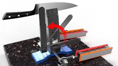
11 Fig. 3 Fig. 4 Fig. 5 Fig. 6 wickededgeusa.com mounting your knife 11
 You may also refer to the Knife Database located on our website to see if someone with a similar knife")


12 SETTING THE ANGLE There are three ways to find your angle. 1. Consult the manufacturer s documentation 2. Use a laser goniometer available from CATRA at 3. Use a marker to color in the bevel and observe how the stones remove the marker (recommended) You may also refer to the Knife Database located on our website to see if someone with a similar knife has recorded their settings. 1. Marker Edge Shoulder Marker Ink on Edge 2 Edge Shoulder This is the procedure for using a marker to find your angle: Color in your bevel as shown in Figure 7-1. Set a fine stone on the Guide Rod and lay it up against the bevel of the knife. Move your Guide Rod until the stone appears to lay flat against the bevel. Then tighten the bottom thumbscrew to fasten the Guide Rod to the Degree Bar. Make a pass or two with the stone, as shown in Figure 8 on the next page, and observe where the marker is removed. If the marker is removed from the bottom of the bevel, as shown in Figure 7-3, then the angle is too narrow. Move your Guide Rod out to the next highest setting, as shown in Figure 9 on the next page. If the marker is removed at the top of the bevel, as shown in Figure 7-4, the angle is too wide. Move the Guide Rod to the next lowest setting and try again. When you find the angle that allows the stone to remove the marker from the entire bevel with one pass, that is the angle of your edge. 3 Edge Blade Detail - (Not to Scale) Fig. 7-1 Fig. 7-2 Shoulder Angle is too narrow move collar out. Fig. 7-3 Fig Edge Shoulder Fine Stone Angle is too wide move collar in Page setting the angle wickededgeusa.com

13 Fig. 8 Fig. 9 wickededgeusa.com setting the angle 13
14 CORRECT POSITIONING The curvature of a knife is an important factor to consider when sharpening because it can affect the sharpening geometry. It is important to position the knife correctly in the clamp. Doing so will let you keep your bevels even, from the heel of the knife to the tip. The easiest way to to find the optimal front-to-back positioning for a given knife is to, again, use a marker. Color in the entire bevel, on both sides. Then, lightly swipe a fine stone down the entire length of the blade to see where the marker is removed. Look closely to see how the stone affects the coloring on the edge. If the stone is removing the marker from the edge along the straight portion but dipping down into the shoulder toward the tip, as shown in Figure 10-2 on the next page, reposition the knife with the tip closer to the clamp. If the opposite happens the stone removes the marker at the shoulder of the bevel along the straight portion and then moves to the edge along the curve, as shown in Figure 10-3 on the next page, then the knife should be repositioned with the tip further from the Vise. Once you find the position where the marker is removed evenly from the entire bevel, as shown in Figure 10-4 on the next page, you have found the optimum positioning for your knife. Any time you reposition your knife, it is important to re-insert the Depth Key and Alignment Guide and record your settings. 14 correct positioning wickededgeusa.com
15 1. 2 Bevel is colored in from Shoulder to Edge with marker. Heel Edge Belly Tip Marker is removed at Edge at the Heel and on the Shoulder at the Tip - Knife is too far forward: reposition with tip closer to clamp. Heel Edge Belly Tip Shoulder Shoulder Fig Fig Marker is removed at Shoulder at the Heel and on the Edge at the Tip - Knife is too far back: reposition with tip further from clamp. Heel Edge Belly Tip Marker is removed parallel to the Edge and Shoulder along the length of the Blade - Knife is correctly positioned. Heel Edge Belly Tip Shoulder Shoulder Fig Fig wickededgeusa.com correct positioning 15


16 MAKING MICRO- ADJUSTMENTS TO YOUR ANGLE SETTINGS Step 1: Loosen the knurled nut on the back side of the L-bracket, opposite the Ball-Joint. See Figure 11-1 Step 2: Use the 1/8" side of your Vise Key to thread the Ball Joint closer to or farther from the Vise, until you reach your desired angle. Figure 11 Step 3: Re-righted the Knurled Nut until it is tight against the L-bracket to lock your angle in place. Note: You will need to use a Digital Angle Gauge to make micro-angle adjustments, available online at Fig Fig making micro-adjustments wickededgeusa.com


17 RECORDING YOUR SETTINGS Recording your angle, alignment, and depth settings is a crucial step in the sharpening process. If your settings are recorded correctly you will be able to touch up your knives in less than a minute and remove virtually no metal. To record your angle settings, record the angle on the Degree Bar that is closest to the inside corner of the L-bracket. To record the depth, write that you have used either the top or bottom depth setting. For the alignment, look at the tip of the knife and compare it to the alignment guide. You can record your settings in the Knife Sharpening Table located on pages 23, 24, and 25. You may also record your settings in the Knife Database on our website so others may use your settings. Once you have recorded your settings, remove the Depth Key and Alignment Guide from the Vise. Fig Fig. 12 wickededgeusa.com recording your settings 17

18 BASIC SHARPENING If this is the first time your knife has been sharpened with a Wicked Edge Sharpener, or if you are changing the angle of the knife's edge, you will need to use the coarse stones to re-profile the edge. Again, mark the entire bevel of the knife, on both sides, with a marker. Slide the 100/200 Grit Diamond Stones Handles onto the Guide Rods. Grasp the handles with your fingers on the indentations, being careful to keep your fingertips behind the finger guards. Place the top of the Red 100 Grit Coarse Stone flat against the heal of the knife. Slide the stone up and away from you, along the entire bevel of the knife. The stroke is done when the bottom of the stone reaches the tip of the knife. When the stone reaches the tip of the knife, be sure to immediately pull the stone out and away and bring it back to the heal of the knife for the next pass. Do not let the stone slide off the tip of the knife while you are applying pressure. Use alternating side-to-side strokes so both sides of the knife are sharpened at the same time. Sharpen until the marker is completely removed from the bevels. Fig basic sharpening wickededgeusa.com
19 CREATING AND DETECTING A BURR 1. Burr When you re first sharpening a blade, successfully drawing a burr from each side of the knife is the most important step. It is very difficult to know for certain without the presence of a burr if the bevels on each side of the blade actually extend to the edge. If the bevels do not extend all the way to the edge, the edge of the knife will be blunt and the knife will not be sharp. A burr, also called a wire edge, is created as a result of sharpening metal. The burr forms on the edge of a knife where the planes of bevels intersect. The diagram to the right shows the burr projecting from the edge of the knife: Once all the marker has been removed from the bevel, try to create a burr on one side of the knife by sharpening the opposite side only. Do approximately 10 strokes on one side of your knife only and then check the opposite side for a burr. You can do this by very carefully feeling the side of the blade by rubbing your fingernail or a cotton ball up the opposite side of the knife, from the spine toward the edge. If you feel it snag on the edge, the burr has been properly formed. Make sure the burr exists throughout the entire length of the knife. Different areas of the knife may require more strokes to successfully form a burr. Do as many strokes as necessary to detect a burr along the entire edge. Once you ve successfully created and detected a burr on one side of the knife, repeat the procedure for the other side. Fig. 14 Edge Bevel Face Side Just Sharpened Blade Detail - (Not to Scale) wickededgeusa.com creating and detecting a burr 19

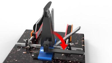
20 PROGRESSING THROUGH YOUR STONES Once you ve successfully created a burr on both sides of the blade, sharpen your knife using alternating side-to-side strokes. Progress through your grits until you achieve the level of polish desired. Note that your stones will need time to break in. We recommend sharpening your inexpensive knives first to let your stones break in. As you spend time using your Wicked Edge Sharpener your technique will become more fluid, your stones will break in, and your results will improve with every knife. Congratulations, you now have a Wicked Edge on your knife! REMOVING YOUR KNIFE Be careful! Your knife is extremely sharp. FIRMLY hold the handle of the knife with one hand and use your other hand to move the Vise Lever to the up position to release the knife, as shown in Figure 15. Fig removing your knife wickededgeusa.com
21 TOUCHING UP YOUR KNIFE When your knife starts to become dull, it's time for a touch-up. The amount of time between touch-ups can vary, depending on the steel, angle, and usage. To bring your edge back to incredible sharpness we recommend starting your grit progression with your finest diamond stone. Simply reference your recorded settings for that particular knife. Mount your knife so the depth, alignment, and angle settings are identical to that which you set during that knife's previous sharpening session. Once everything is set, draw a burr from one side. Then sharpen the opposite side and push the burr to the other direction. Once you have found the burr on both sides, do approximately 20 strokes with your diamond stones, on each side of the knife. If you have purchased any additional fine stones or strops, progress through them until you reach a level of sharpness and polish that you are happy with. WE'RE HERE TO HELP! If you have any questions please feel free to or call us. Here's our contact info: Support@wickededgeusa.com Toll Free: (877) Hours: 9:00 A.M. To 5:00 P.M. Mountain Time wickededgeusa.com touching up your knife 21

22 ASSEMBLE YOUR WICKED EDGE Step 1: Position the Degree Bar in the bottom channel of the Base with the numbers facing up and the detents facing the same direction as the logo on the Base as shown in Figure 16. Step 2: Note that only one hole in the Base is threaded. Insert the 1/2 inch Socket-Head Cap Screw into the hole in the Degree Bar that is lined up with the threaded hole in the Base. Then fasten the Degree Bar to the Base. Do not over tighten. Step 3: Place the Generation 3 Vise into the channel on the top of the Base so the Cam Shaft is facing the same direction as the logo on the base. Then fasten the Degree Bar, Base, and Generation 3 Vise together using the 7/8" Socket Cap Screw. Do not over tighten. Fig assembly guide wickededgeusa.com
23 WICKED EDGE KNIFE SHARPENING TABLE Brand Model Angle Mark Depth Brand Model Angle Mark Depth Sample 10xx 22 C 0.5 Top wickededgeusa.com knife sharpening table 23
24 WICKED EDGE KNIFE SHARPENING TABLE Brand Model Angle Mark Depth Brand Model Angle Mark Depth 24 knife sharpening table wickededgeusa.com
25 WICKED EDGE KNIFE SHARPENING TABLE Brand Model Angle Mark Depth Brand Model Angle Mark Depth wickededgeusa.com knife sharpening table 25
26 WICKED EDGE KNIFE SHARPENER WARRANTY STOP!! BEFORE USING THIS PRODUCT YOU MUST READ THE FOLLOWING PRODUCT WARRANTY, DISCLAIMERS AND WARNINGS! Wicked Edge (a division of HollowPoint, LLC) offers a Limited Lifetime Warranty to the purchaser of the knife sharpener, for defects in materials and workmanship. The knife sharpener is not made for, designed for, nor intended to be, used for any purpose other than as specified in the Instructions. Any use of the knife sharpener, for any activity whatsoever, other than that for which the knife sharpener was intended, is done at the purchaser s own risk. The knife sharpener is to be used only with knives in good condition that are not damaged or otherwise faulty. It is the purchaser s sole responsibility to read the Instructions thoroughly. Extreme care must be used when installing, mounting and using the knife sharpener to avoid serious accident, injury, or death. Wicked Edge will not be responsible for damage to the knife sharpener while being mounted. By purchasing the knife sharpener, the purchaser agrees and acknowledges that the knife sharpener is an inherently dangerous tool that can cause injury, even in the course of ordinary use, and even if used for the purpose for which the knife sharpener was intended. Therefore, the purchaser agrees and acknowledges that Wicked Edge cannot be responsible or liable in any way for injury, accident, bodily harm (including death) or other such trauma that may arise out of the purchaser s use or misuse of the knife sharpener, whether used in the course of sharpening knives or otherwise, regardless of whether such use was for the purpose for which the knife sharpener was intended. THE PURCHASER HEREBY EXPRESSLY RELEASES WICKED EDGE, ITS EMPLOYEES, AGENTS, OFFICERS, DIRECTORS AND MEMBERS, FOR ANY AND ALL LIABILITY, INCLUDING DAMAGES, INJURY, ACCIDENT, BODILY HARM (INCLUDING DEATH) OR OTHER SUCH TRAUMA, THAT MAY RESULT FROM PURCHASER S USE OR MISUSE OF THE KNIFE SHARPENER, OR USE OR MISUSE OF KNIVES IN CONNECTION WITH THE KNIFE SHARPENER. Wicked Edge s obligation under this warranty is limited to the replacement of the knife sharpener only. All costs related to the removal, installation or re-installation of the knife sharpener, freight charges, incidental or consequential damages, are expressly excluded from this warranty. This warranty is expressly in lieu of all other warranties, expressed or implied. This warranty SHALL NOT apply to any knife sharpener that has been subject to accident, negligence, alteration, abuse or misuse as determined at the sole discretion of Wicked Edge. 26 warranty wickededgeusa.com

27 precision k nife sharpeners
28 Wicked Edge 1591 Pacheco Street, Bldg 2 Santa Fe, NM USA (877) Wicked Edge All Rights Reserved. precision k nife sharpeners W W W. W I C K E D E D G E U S A. C O M
V-Groover SIMPLEX INSTRUCTION AND OPERATION MANUAL M O DEL 703. For best results use only authentic Logan blades.
 www.logangraphic.com SIMPLEX M O DEL 703 INSTRUCTION AND OPERATION MANUAL For best results use only authentic Logan blades CAUTION: BLADES EXTREMELY SHARP Use replacement blades #1258 Logan Graphic Products,
SawStop. T-GlideTM. Fence System- Professional Series II OWNER S MANUAL
 SawStop T-GlideTM Fence System- Professional Series II OWNER S MANUAL Warranty SawStop warrants to the original retail purchaser of a new T-Glide Fence System - Professional Series II from an authorized
PRAZI USA. Model PR-3900 Owners Manual. Please read this manual in its entirety before using the PRAZI ChestMate.
 PRAZI USA Model PR-3900 Owners Manual Please read this manual in its entirety before using the PRAZI ChestMate. PRAZI USA 214 Rear South Meadow Rd (800)-262-0211 Plymouth MA, 02360 www.praziusa.com ChestMate
SawStop. Contractor Fence Assembly OWNER S MANUAL. Model CNS-SFA
 Contractor Fence Assembly OWNER S MANUAL Model CNS-SFA Warranty warrants to the original retail purchaser of the Contractor Fence Assembly accompanying this manual that the fence assembly will be free
00108/00110 INSTRUCTION MANUAL
 00108/00110 INSTRUCTION MANUAL Removable and Adjustable Mudflap System IMPORTANT! Please Read this Instruction Booklet prior to assembly of your Rock Tamer Kit. IMPORTANT! Exhaust Systems Note: Any modifications
MODEL M1023 QUICK CHANGE COLLET ATTACHMENT INSTRUCTION MANUAL. Phone: On-Line Technical Support:
 MODEL M1023 QUICK CHANGE COLLET ATTACHMENT INSTRUCTION MANUAL Phone: 1-360-734-3482 On-Line Technical Support: tech-support@shopfox.biz #6727BL COPYRIGHT JANUARY, 2005 BY WOODSTOCK INTERNATIONAL, INC.
Assembly Instructions and Parts Manual JPSF-1 Fence and JPSR Rail Set #
 Assembly Instructions and Parts Manual JPSF-1 Fence and JPSR Rail Set #1002493 JET 427 New Sanford Road LaVergne, Tennessee 37086 Part No. M-708482 Ph.: 800-274-6848 Revision C3 02/2014 www.jettools.com
# in 1 Metal Worker Auxiliary Operating Instructions
 340 Snyder Avenue, Berkeley Heights, NJ 07922 www.micromark.com MMTechService@micromark.com Tech Support: 908-464-1094, weekdays, 1pm to 5 pm ET #86556 3 in 1 Metal Worker Auxiliary Operating Instructions
INSTALLATION & OPERATING INSTRUCTIONS. REDCO LETTUCE KING I and LETTUCE KING IV
 INSTALLATION & OPERATING INSTRUCTIONS for REDCO LETTUCE KING I and LETTUCE KING IV Lettuce King I Shown with optional Drum Ring Lettuce King IV TO BE SERVICED ONLY BY AUTHORIZED PERSONS P/N: 2802381 REV:
PRECISION KNIFE SHARPENING SYSTEM USER MANUAL
 PRECISION KNIFE SHARPENING SYSTEM USER MANUAL * Knife not included Thank you for purchasing FINO EDGE Precision Knife Sharpening System! A C F J I E B D G H մbox Contents A Heavy-Duty Base Plate with 3
Tilting, Swiveling & Rotating Flat Panel Wall Mount
 Tilting, Swiveling & Rotating Flat Panel Wall Mount Model: VXA980TC +5 to -5 +5 to -5 Supports most 0-80 Flat Panel TVs Maximum Weight Capacity: 32 lbs. Supports VESA Sizes up to 600x500 For technical
INSTRUCTION BOOK AND PARTS LIST
 Rag Cutter MODEL WE WARNING This machine is equipped with a very sharp knife. Keep hands, arms, and hair away from the knife area at all times. Misuse of this machine or failure to follow all safety instructions
OWNER S MANUAL - ShopStrop
 OWNER S MANUAL - ShopStrop Precision Sharpening System Part Number SS-S (28289) CAUTION: Before using your ShopStrop Precision Sharpening System, read this manual and follow all its Safety and Operating
Owner s Manual GS2010 Garden Seeder/Fertilizer. Caution: Carefully read all Rules and Instructions for Safe Operation.
 Manufacture s Limited Warranty for The limited warranty set forth below is given by Precision Products, Incorporated with respect to new merchandise purchased and used in the United States, its possessions
Models 2230 and 2240
 Models 2230 and 2240 Overview... 2 Tools Needed... 2 Hardware...3 Assembly... 4-13 Installation... 14 Drawer Removal... 15 Operation... 15 Maintenance... 15 Accessories... 16 Limited Warranty... 16 Perform
Sunset Swings By Health in Motion, LLC
 Sunset Swings By Health in Motion, LLC Model 421 Lounge Swing Assembly and Operation Manual Record Serial Number Here www.sunsetswings.com by Health In Motion, LLC. 11/6/2009 421 Owners Assembly and Operation
COMPACT XL MAT CUTTER
 INSTRUCTION MANUAL MODEL 380-1 COMPACT XL MAT CUTTER INSTRUCTIONS AND OPERATION MANUAL 40in (101cm) mat cutting system with bevel & straight cutters For best results use only authentic Logan blades Uses
INSTRUCTION MANUAL TAPER ATTACHMENT MODEL M1022. Phone: (360) On-Line Technical Support: FOR USE WITH MODEL M1019
 On-Line Technical Support: FOR USE WITH MODEL M1019") MODEL M1022 TAPER ATTACHMENT FOR USE WITH MODEL M1019 INSTRUCTION MANUAL Phone: (360) 734-3482 On-Line Technical Support: tech-support@shopfox.biz #6809BL COPYRIGHT DECEMBER, 2004 BY WOODSTOCK INTERNATIONAL,
MODEL M1022 TAPER ATTACHMENT FOR USE WITH MODEL M1019 INSTRUCTION MANUAL Phone: (360) 734-3482 On-Line Technical Support: tech-support@shopfox.biz #6809BL COPYRIGHT DECEMBER, 2004 BY WOODSTOCK INTERNATIONAL,
Assembly Instructions and Parts Manual JPSF-1 Fence and JPSR Rail Set
 Assembly Instructions and Parts Manual JPSF-1 Fence and JPSR Rail Set WALTER MEIER (Manufacturing) Inc. 427 New Sanford Road LaVergne, Tennessee 37086 Part No. M-708482 Ph.: 800-274-6848 Revision C2 02/2013
F-150 Structural Holding System
 F-150 Structural Holding System Users Manual December 2013 by Vehicle Service Group. All rights reserved. CO8812.2 502073 Rev. - 12/11/2013 CHIEF'S LIMITED ONE-YEAR WARRANTY & LIABILITY Chief Automotive
600mm COMPOUND MITRE SAW ASSEMBLY INSTRUCTIONS. MODEL NO: MBS600D Part No: GC05/12
 600mm COMPOUND MITRE SAW MODEL NO: MBS600D Part No: 6461516 ASSEMBLY INSTRUCTIONS GC05/12 INTRODUCTION Thank you for purchasing this CLARKE Mitre Saw. Before attempting to use the product, it is essential
INSTALLATION INSTRUCTIONS
 CREATING POSITIVE CUSTOMER EXPERIENCES INSTALLATION INSTRUCTIONS PDS-PLUS Universal Projector Mount Model: NORTH AMERICA 3130 East Miraloma Avenue Anaheim, CA 92806 USA USA and Canada Phone: 1.800.368.9700
OWNER S MANUAL with Assembly Instructions
 OWNER S MANUAL with Assembly Instructions VISIT E LIFETIME WEB SITE: WWW.LIFETIME.COM ** Do Not Contact the Store ** For Assistance, including missing or broken parts, Call Customer Service at: 1 (800)
9 QUICK RELEASE WOODWORKING VISE
 9 QUICK RELEASE WOODWORKING VISE 94386 OPERATING INSTRUCTIONS Due to continuing improvements, actual product may differ slightly from the product described herein. 349 Mission Oaks Blvd., Camarillo, CA
Narrow Rail Vise Attachment USERS MANUAL
 Narrow Rail Vise Attachment USERS MANUAL 2006 Chief Automotive Technologies, Inc. Chief s Limited One-Year Warranty & Liability CHIEF'S LIMITED ONE-YEAR WARRANTY & LIABILITY Chief Automotive Technologies,
HUSTLER 7' & 8' POOL TABLE ASSEMBLY INSTRUCTIONS
 HUSTLER 7' & 8' POOL TABLE ASSEMBLY INSTRUCTIONS Please Do Not Hesitate to Contact Our Consumer Hotline at 800-759-0977 with Any Questions That May Arise During Assembly or Use of This Product! NG2515PB/NG2520PB
Models 2130 and 2140
 Models 2130 and 2140 Overview... 2 Tools Needed... 2 Hardware... 2 Assembly... 3-10 Installation...11 Operation... 11 Maintenance... 12 Accessories...12 Limited Warranty... 12 Printed in USA 2007 Perform
Spa & Hot Tub Necessities. Cover Removal System Installation & Use Manual
 Spa & Hot Tub Necessities Cover Removal System Installation & Use Manual SET-UP AND ASSEMBLY BEFORE BEGINNING ASSEMBLY, CAREFULLY READ THE FOLLOWING INFORMATION AND INSTRUCTIONS: Place all parts in a cleared
MODEL T28000 HEAVY-DUTY MOBILE BASE INSTRUCTIONS
 MODEL T28000 HEAVY-DUTY MOBILE BASE INSTRUCTIONS For questions or help with this product contact Tech Support at (570) 546-9663 or techsupport@grizzly.com Introduction Your new Model T28000 Heavy-Duty
Fletcher F-3000 / F-3100 Accessory Laser Kit
 Fletcher F-3000 / F-3100 Accessory Laser Kit Shown Assembled on F-3000 Machine Product Warranty The Fletcher-Terry Company warrants the product purchased to be free from defects in parts and workmanship
Models 2030 and 2040
 Models 2030 and 2040 Overview... 2 Tools Needed... 2 Hardware... 2 Assembly... 3-8 Installation... 9 Operation... 9 Maintenance... 10 Accessories... 10 Limited Warranty... 10 Document # 101290 0607 Printed
Tilting Flat Panel Wall Mount Installation Guide
 Tilting Flat Panel Wall Mount Installation Guide Model: A580TM Easy installation Built-in level for easy positioning Safety bolts lock the TV on the mount Easy to adjust tilt angles: +5 to -15 degrees
CT Box and Pan Brake User Manual
 CT153 12 Box and Pan Brake User Manual Important Safety Precautions Plead read all the instructions before using this tool. 1) Always keep your work area clean. Cluttered areas invite injuries. 2) Do not
SIMPLEX ELITE MAT CUTTER
 INSTRUCTION MANUAL MODEL 750-1 / 760-1 SIMPLEX ELITE MAT CUTTER INSTRUCTIONS AND OPERATION MANUAL 40 in (101 cm) mat cutting system with bevel & straight cutters, production stops, 27 in (68 cm) squaring
Check us out on-line! Installation Instructions
 Installation Instructions 2 OPTIONAL ACCESSORIES Order Quantum Rack Accessories Online at www.dawsbetterbuilt.com Cargo Lock Kit Secure Your Load Cargo Locks can easily be installed and adjusted left or
PRIMO 56" FOOSBALL TABLE ASSEMBLY INSTRUCTIONS
 PRIMO 56" FOOSBALL TABLE ASSEMBLY INSTRUCTIONS NG1035 THANK YOU! Thank you for purchasing this product. We work around the clock and around the globe to ensure that our products maintain the highest possible
Biesemeyer fi T-Square fi Commercial Fence Systems 50 Capacity (Model ) 30 Capacity (Model ) INSTRUCTION MANUAL
 30 Capacity (Model ) INSTRUCTION MANUAL") iesemeyer fi T-Square fi Commercial Fence Systems 50 Capacity (Model 78-904) 30 Capacity (Model 78-907) INSTRUCTION MNUL D T E D 3-5-96 P RT NO. 1349984 'Delta International Machinery Corp. 1996 INTRODUCTION
iesemeyer fi T-Square fi Commercial Fence Systems 50 Capacity (Model 78-904) 30 Capacity (Model 78-907) INSTRUCTION MNUL D T E D 3-5-96 P RT NO. 1349984 'Delta International Machinery Corp. 1996 INTRODUCTION
Models 2130 and 2140
 Models 2130 and 2140 Overview... 2 Tools Needed... 2 Hardware... 2 Assembly... 3-10 Installation...11 Operation... 11 Maintenance... 12 Accessories...12 Limited Warranty... 12 Perform the following sequence
Assembly & Installation Instructions
 Wall Mount Hose Reel Model 04-GH Configuration Pulls the hose out straight away from the wall. Configuration Pulls the hose out along side the wall. Assembly & Installation Instructions Version 0409 A
Shop Style Miter Saw Stand Kit
 Quality Power Tool Accessories OWNER S MANUAL Assembled Unit Shown Without Shelves & Wings Assembled With Shelves & Wings Shop Style Miter Saw Stand Kit Model 2850 IMPORTANT Read and understand all safety
Planishing hammer stand For use with SKU Planishing hammer
 Planishing hammer stand For use with SKU 94847 Planishing hammer Model 96300 Assembly And Operation Instructions Please Note: Planishing Hammer not included with Stand. Due to continuing improvements,
Tilting & Swiveling Plasma/LCD Flat Panel Wall Mount Installation Guide Model: A380SM
 Tilting & Swiveling Plasma/LCD Flat Panel Wall Mount Installation Guide Model: A380SM Easy installation Built-in level for easy positioning Corrective leveling adjustments after installation Forward /
Owner s Manual AE PLUG AERATOR MANUFACTURING QUALITY LAWN CARE EQUIPMENT SINCE Made In CHINA REV
 MANUFACTURING QUALITY LAWN CARE EQUIPMENT SINCE 1945 Owner s Manual AE-48 48 PLUG AERATOR IMPORTANT Read and follow all Safety Precautions and Instructions Before Operating this Equipment. Made In CHINA
PRAZI USA. Model PR-3900 Owners Manual. Please read this manual in its entirety before using the PRAZI ChestMate.
 PRAZI USA Model PR-3900 Owners Manual Please read this manual in its entirety before using the PRAZI ChestMate. PRAZI USA 214 Rear South Meadow Rd (800)-262-0211 Plymouth MA, 02360 www.praziusa.com ChestMate
Assembly Instructions and Parts Manual 5C Collet Closer for GHW Lathes Model CC-GHW
 Assembly Instructions and Parts Manual 5C Collet Closer for GHW Lathes Model CC-GHW JET 427 New Sanford Road LaVergne, Tennessee 37086 Part No. M-321519 Ph.: 800-274-6848 Revision G1 03/2014 www.jettools.com
BASE & WALL CABINET SETUP GUIDE BY SUNSTONE
 BASE & WALL CABINET SETUP GUIDE BY SUNSTONE Read all instructions before you install cabinet. Very important to follow each step in order as detailed in this Instruction Guide!!! To installer or person
CRD 410 MANUAL FITTING INSERTER
 CRD 410 MANUAL FITTING INSERTER OPERATIONS MANUAL VERSION 1.2 LAST EDITED 05.01.2018 cleanroomdevices.com 1 Table of Contents Title Page 1 Table of Contents 2 1.0 General Product & Safety Information...3
Owners Manual AGBAY Single Blade Levelers (20 Agbay & 12 Agbay Jr.)
") Owners Manual AGBAY Single Blade Levelers (20 Agbay & 12 Agbay Jr.) Made In USA Adjustment Knobs Adjustment Rod Frame Stainless Steel Blade Stainless Steel Scales Feet Blade Guard Jr. Model Shown Agbay
Owners Manual AGBAY Single Blade Levelers (20 Agbay & 12 Agbay Jr.) Made In USA Adjustment Knobs Adjustment Rod Frame Stainless Steel Blade Stainless Steel Scales Feet Blade Guard Jr. Model Shown Agbay
INSTALL INSTRUCTIONS WELCOME TO THE NEWAGE PERFORMANCE CABINETRY SERIES NEWAGE STEEL WELDED CABINETRY
 NEWAGE STEEL WELDED CABINETRY WELCOME TO THE NEWAGE PERFORMANCE CABINETRY SERIES ALL CABINETS MUST BE MOUNTED TO STUDS ON A SECURE WALL, AS PER THESE INSTRUCTIONS. FAILURE TO DO SO MAY RESULT IN SERIOUS
INSTRUCTIONS FOR ASSEMBLY AND OPERATION OF ERMA MICROTOME
 OPERATING MANUAL, ERMA RADIAL INSTRUCTIONS FOR ASSEMBLY AND OPERATION OF ERMA MICROTOME Upon receipt of your Erma Microtome please check the contents of the packages (s). These are itemized below: 1. Microtome
MODEL T " HELICAL CUTTERHEAD INSTALLATION INSTRUCTIONS
 MODEL T27696 12" HELICAL CUTTERHEAD INSTALLATION INSTRUCTIONS For questions or help with this product contact Tech Support at (570) 546-9663 or techsupport@grizzly.com Introduction The Model T27696 indexable
BOUNCE TABLE TENNIS TABLE & ACCESSORIES ASSEMBLY INSTRUCTIONS
 BOUNCE TABLE TENNIS TABLE & ACCESSORIES ASSEMBLY INSTRUCTIONS NG2325 THANK YOU! Thank you for your purchase of our product. We work around the clock and around the globe to ensure that our products maintain
User Manual. Where Imagination Meets Innovation. FRESH AERO Easy Seat Tool For Grumman AA1 & AA5 Series Aircraft
 FRESH AERO Easy Seat Tool For Grumman AA1 & AA5 Series Aircraft Alpha Model For Grumman AA-1 & AA-5 Series Aircraft with Access Holes in Front Seat Buckets User Manual The Steelebrook Group Where Imagination
OWNER S MANUAL. Safety. Please read this owner s manual before use and keep it at hand for reference. Warranty
 Please read this owner s manual before use and keep it at hand for reference. OWNER S MANUAL Safety Important safety instructions for using the INCRA Miter5000 Before using the INCRA Miter5000, read and
Thorvie Instructions Always wear eye protection and do not wear loose clothing when operating machinery. FOR AV- 41 ICE AUGER MACHINE
 FOR AV- 41 ICE AUGER MACHINE 1. Please study video and all instructions before proceeding to grind. For Mora, Jeffy and Eskimo blades use the 6 brown resin bond wheel. Mount with washer and left-hand nut
Record the serial number and date of purchase on your parts list for future reference.
 Jointer Model: 0-0 Parts List Record the serial number and date of purchase on your parts list for future reference. Serial number: Date of purchase: Part # 0-0PL For more information: www.rikontools.com
SIMPLEX STUDIO ELITE MAT CUTTER
 INSTRUCTION MANUAL MODEL 700- SIMPLEX STUDIO ELITE MAT CUTTER INSTRUCTIONS AND OPERATION MANUAL 0 inch (50 cm) capacity mat cutting system with bevel & straight cutters, production stops and squaring arm
AST-2446 INSTALLATION INSTRUCTIONS
 AST-2446 Suspension Adapter AST-2446 INSTALLATION INSTRUCTIONS Single Stud Installation Step 1. Secure the ceiling plate to the ceiling structure (see WARNING). Step 2. Use suitable hardware (commercially
Guitar Mobile Storage Rack
 Assembly Instructions Guitar Mobile Storage Rack CONTENTS Safety Precautions.................................. 2 Warranty.......................................... 2 Operation.........................................
OPERATOR S MANUAL Model 77E Pneumatic Cable Stripper
 110 Fairgrounds Drive P.O. Box 188 Manlius, NY 13104-0188 USA 315.682.9176 FAX: 315.682.9160 OPERATOR S MANUAL Model 77E Pneumatic Cable Stripper PRODUCTION WIRE PROCESSING EQUIPMENT Website: www.carpentermfg.com
Owner s Manual ODYSSEY BENCH MODEL. O4100B shown REV E. Southern Avenue, Phoenix, AZ USA Workhorseproducts.
 Owner s Manual ODYSSEY BENCH MODEL O4100B shown 67-1375 REV 218 3730 E. Southern Avenue, Phoenix, AZ 85040 USA 800-778-8779 Workhorseproducts.com 1 Table of Contents I. Introduction & Safety Information.
MODEL SETUP & OPERATION MANUAL DOVETAIL JIG FEATURES
 SETUP & OPERATION MANUAL FEATURES New clamping system for greater accuracy. Lockable template height for a stable platform for the router. Cuts precision matching dovetails with the same accuracy found
Vicmarc Grinding System
 Vicmarc Grinding System User Manual Vicmarc Sharpening Jig Part No. V00437 Vicmarc Grinding Rest Part No. V00438 Vicmarc Machinery Pty Ltd Manufacturer of Quality Woodturning Lathes and Accessories Vicmarc
Specifications. Important Safety Information
 Specifications Tire Rim Capacity 4 to 12 Rim Height 16 (2) Bead Breaker Handles 21 Long Includes Aluminum Centering Cone (2) Nylon Spacers Important Safety Information 1. Do not exceed max. tire capacity.
Simplex Studio. Model 700-S MAT CUTTER INSTRUCTION AND OPERATION MANUAL
 Model 700-S Simplex Studio 22 1 /2" Mat cutting system with production stops, parallel mat guide, flush cut squaring arm, including straight and bevel cutting heads. MAT CUTTER www.logangraphic.com For
Model Assembly & Operating Instructions
 30 SHEAR BRAKE ROLL Model 05907 Assembly & Operating Instructions Diagrams within this manual may not be drawn proportionally. Due to continuing improvements, actual product may differ slightly from the
VAN STORAGE SOLUTIONS FOR THE WAY YOU WORK
 WWW.WEATHERGUARD.COM VAN STORAGE SOLUTIONS FOR THE WAY YOU WORK Weather Guard / KNAACK 420 E. Terra Cotta Ave. Crystal Lake, IL 60014 USA 800-456-7865 (Toll Free) 800-334-2981 (Fax) Knaack.OrderEntry@wernerco,.com
Assembly Instructions
 Assembly Instructions Workbench Model: GR 1902 (Tan) Dimensions (D x W x H): 24 x 48 x 60 GR1902B (Black) For Instruction Assistance (800) 736-7225 WEEKDAYS: 8:00 a.m. - 5:00 p.m. Pacific Standard Time
Swoop Classic. Please read and understand all instructions before beginning installation. Any Questions?
 Version 1.1 4/27/2004 1 Top Section (1) 2 Mid Sections (2) 3 Lower Support Arms (2) 4 3/8-16 x 1 1/4 SS Socket Head Cap Screw (8) 5 1 1/2 Quick Release Knobs (2) 6 1/2-20 SS Heim Joints (2) 7 1/4 Neopreme
-Eagle Edger Jr Linear Edge Add-on for the Blue Ripper Jr
 -Eagle Edger Jr Linear Edge Add-on for the Blue Ripper Jr (Blade shown might not ship with tool, or be available.) Operation, Safety, and Instruction Manual v20150521 Page 2 Operating/Safety Instructions
Mount to the Wall INSTALLATION MANUAL
 Mount to the Wall 15 Locate the Wooden Studs This step applies to wooden stud wall installation only. Determine and mark the exact locations of two stud centers on the wall. Wooden studs should be spaced
MODEL T " SPIRAL CUTTERHEAD INSTRUCTIONS
 MODEL T10125 6" SPIRAL CUTTERHEAD INSTRUCTIONS The Model T10125 spiral cutterhead is designed to replace the straight knife cutterhead on the Model G0452 6" jointer. The total procedure of changing the
installation guide 1 GUIDE#: pwb-assault-004
 assault WAKEBOARD tower installation guide INSTALLATION SUPPORT 1 important information This Aerial wakeboard tower fits motor boats with 76-108 inch wide beam widths. This measurement is taken from the
EllisSaw.com. EllisSaw.com P.O. Box Verona, WI
 P.O. Box 9019 Verona, WI 9-019 GENERAL OPERATING & SAFETY INSTRUCTIONS * READ INSTRUCTIONS BEFORE USE * CAUTION: Disconnect power supply cord from power source when doing repair work or changing belt.
Elimination of Elevator Bounce
 For the Agilent Archon Autosampler Rework Instructions CAUTION This kit is intended for use by Agilent Service personnel only. Elevator Removal 1 Open top cover. 2 Open front lower door. 3 Remove vial
Powered by. For further installation assistance: prxperformance.com/pages/murphy-rack
 Powered by The 90 Fold-in Murphy Rack is made by the creators of the original Profile Folding Rack at PRx Performance and is Patent Pending. An up-to-date record of patents and patent pending items can
Sea Doo Spark Engine Access Kit
 Sea Doo Spark Engine Access Kit PART# - RS4-130-EAK APPLICATION(S): Sea Doo Spark. 2up & 3up Models. We strongly recommend the use of a service manual to familiarize yourself with the various components
ApexDesk Assembly Guide
 ELECTRIC HEIGHT-ADJUSTED SIT TO STAND DESK ApexDesk Assembly Guide REV-1507C Table of Contents CAUTION, USE & LIABILITY... 3 PARTS & HARDWARE LIST... 4 PARTS / COMPONENT DIAGRAMS... 5 ASSEMBLY INSTRUCTIONS...
Adjustable Performance Trim Tab Kit PART# - RS27110-APT
 Adjustable Performance Trim Tab Kit PART# - RS27110-APT APPLICATION(S): Sea Doo RXP-X 260 We strongly recommend the use of a service manual to familiarize yourself with the various components and procedures
HAINSWORTH WRITING DESK ASSEMBLY INSTRUCTIONS
 Item# BP-HSWD52-W8 HAINSWORTH WRITING DESK ASSEMBLY INSTRUCTIONS IF PARTS ARE MISSING OR DAMAGED, DO NOT RETURN TO STORE To order missing or replacement parts, contact us via e-mail parts@officestar.net,
INSTALLATION INSTRUCTIONS
 CREATING POSITIVE CUSTOMER EXPERIENCES INSTALLATION INSTRUCTIONS Universal Low Profile Tilt Mount for 42 to 63 Flat Panels NORTH AMERICA 3130 East Miraloma Avenue Anaheim, CA 92806 USA USA and Canada Phone:
Bench Grinder Sharpening Jig Kit
 Owner s Manual Model No. 71021 Bench Grinder Sharpening Jig Kit Visit us on the web at www.southerntechllc.com You will need this manual for safety instructions, operating procedures, and warranty. Put
NOVA-EXT Versatile Projector Mount Model: NOVA-EXT
 INSTALLATION MANUAL NOVA-EXT Versatile Projector Mount Model: NOVA-EXT NORTH AMERICA 3130 East Miraloma Avenue Anaheim, CA 92806 USA USA and Canada Phone: 800-368-9700 Fax: 800-832-4888 Other Locations
Assembly Instructions and Parts Manual 5C Collet Closer for ZX Series Lathes Model CC-ZX
 Assembly Instructions and Parts Manual 5C Collet Closer for ZX Series Lathes Model CC-ZX JET 427 New Sanford Road LaVergne, Tennessee 37086 Part No. M-321292 Ph.: 800-274-6848 Revision B 03/2014 www.jettools.com
orientation Conergy SunTop Instructions for professional installation
 On-roof Framed modules Portrait orientation Landscape Three-tab Shingle Plain tile Slate Double Roman tile Metal roof Material warranty orientation Conergy SunTop Instructions for professional installation
Ball-Joint Scrapers Steel Blade Carbide Blade 05K K21.04
 Ball-Joint Scrapers Steel Blade Carbide Blade 05K21.01 05K21.04 The Veritas Ball-Joint Scraper is based on a tool originally made by L.S. Starrett Tool Company but out of production for many years. Originally
model tsa-sa48 Sliding Crosscut Table installation guide
 model tsa-sa48 Sliding Crosscut Table installation guide A Note About Color Variations Among Anodized Aluminum Components Congratulations on the purchase of this SawStop Sliding Crosscut Table. We at SawStop
Installation Instructions Hinged Roof Rack
 Installation Instructions Hinged Roof Rack Application: Jeep Wrangler Unlimited 2004 - Current Part Number: 41435-01 www.bestop.com - We re here to help! Visit our web site and click on Ask a Question
ATTENTION: PLEASE READ AND UNDERSTAND ALL INSTRUCTIONS AND WARNINGS BEFORE ASSEMBLING, INSTALLING OR USING THIS PRODUCT.
 PLAN YOUR VAN (TIPS FOR FASTER INSTALLATION) Installing your Transit bulkhead is very clear cut following these instructions. Before cutting or drilling in the floor, verify the location of you gas tank,
INSTRUCTION BOOK FOR. IDEA Screen & Panoramic for Nureva Span
 INSTRUCTION BOOK FOR IDEA Screen & Panoramic for Nureva Span Disclaimer Milestone and its affiliated corporations and subsidiaries (collectively "Milestone"), intend to make this manual accurate and complete.
Tilting & Swiveling Flat Panel Wall Mount Installation Guide Model: AXS2040
 Tilting & Swiveling Flat Panel Wall Mount Installation Guide Model: AXS2040 20-40 66 lbs. Supports VESA sizes up to: 200x200 For technical assistance or troubleshooting please call 1-855-994-2825 or visit
 Menu Board Tilt or Fixed Mount Installation Instructions MDS1T-200, MDS1T-300, MDS1T-400 MDS2T-200, MDS2T-300, MDS2T-400 MDS3T-200, MDS3T-300, MDS3T-400 MDS4T-200, MDS4T-300, MDS4T-400 MDS5T-200, MDS5T-300,
Assembly & Installation Instructions
 Wall Mount Garden Hose Reel Model 1041 Assembly & Installation Instructions 1 2 3 4 5 6 8 9 10 12 15 7 11 10 16 17 13 14 CONTENTS QUESTIONS? PROBLEMS? Please DO NOT contact or return this item to the retailer.
Single Flex and Double Flex Couplings (i)
") Single Flex and Double Flex Couplings (i) FORM NO. L00G00 In accordance with Nexen s established policy of constant product improvement, the specifications contained in this manual are subject to change
Single Flex and Double Flex Couplings (i) FORM NO. L00G00 In accordance with Nexen s established policy of constant product improvement, the specifications contained in this manual are subject to change
Assembly Instructions and Parts Manual Taper Attachment for Bench Lathes Model TAK-13GH/BD
 Assembly Instructions and Parts Manual Taper Attachment for Bench Lathes Model TAK-13GH/BD JET 427 New Sanford Road LaVergne, Tennessee 37086 Part No. M-321442 Ph.: 800-274-6848 Revision B 03/2014 www.jettools.com
Rojek Woodworking Machinery Interchangeable Shaper Spindle Installation and User s Guide
 Rojek Woodworking Machinery Interchangeable Shaper Spindle Installation and User s Guide Part #: ROJ-PUB-IS-SPINDLE Ver #: 0311 Contents Section 1: Introduction...5 Safety Instructions... 5 Delivered Components
Loading Dock Safety Gate
 Installation Instructions/Operation and Maintenance Manual Models LDSG-120-PCY LDSG-144-PCY Table of Contents Product Information...2 Parts List...3 Installation Instructions...5 Operation...13 Inspection
Fletcher-Terry Titan Series Rotary Trimmers
 Fletcher-Terry Titan Series Rotary Trimmers Instruction Manual Provided By http://www.mybinding.com http://www.mybindingblog.com OWNER S MANUAL Fletcher Titan The Fletcher-Terry Company 65 Spring Lane
INSTALLATION INSTRUCTIONS: DISC SANDER SHIELDS UPPER BELT SANDER SHIELDS LOWER BELT SANDER SHIELDS
 INSTALLATION INSTRUCTIONS: DISC SANDER SHIELDS UPPER BELT SANDER SHIELDS LOWER BELT SANDER SHIELDS Disc Sander s Upper and Lower Belt Sander s 4620 Hydraulic Road Rockford, Illinois 61109 Toll-Free 1-800-922-7533
Your Performance Partner
 Assembly Instructions Attic Storage System Your Performance Partner CONTENTS Safety Precautions.................................. 2 Warranty.......................................... 2 Important User Information............................